

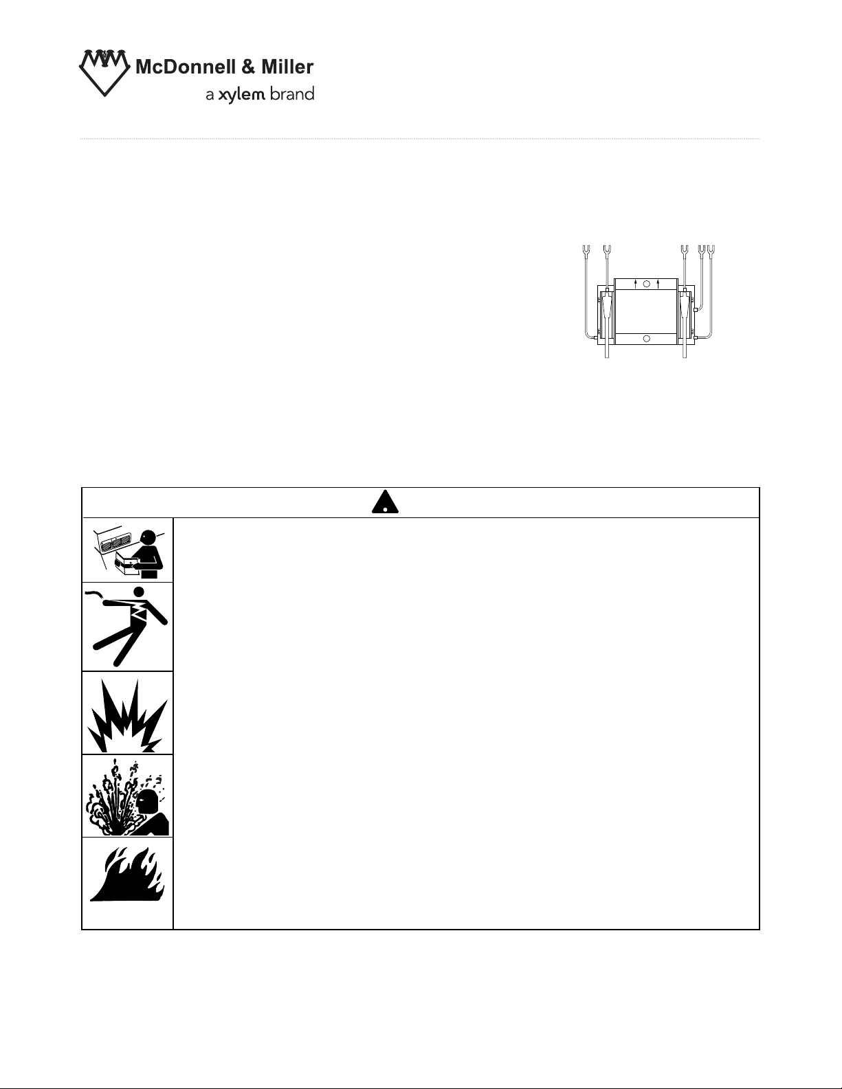
Replacement Snap Switch Assembly
SWA-150S SWA-158S
SWA-150S-MD SWA-159S
For Series 150S and 157S Low
Water Cut-Off/Pump Controllers
(All Models)
INSTRUCTION MANUAL
MM-235E
Replacement Switch Assembly
WARNING
!
CAUTION
WARNING
• Before using this product read and understand instructions.
• Save these instructions for future reference.
• All work must be performed by qualified personnel trained in the proper application, installation, and maintenance of plumbing, steam, and electrical equipment and/or systems in
accordance with all applicable codes and ordinances.
• To prevent serious burns, the boiler must be cooled to 80˚F (27˚C) and the pressure must be
0 psi (0 bar) before servicing.
• To prevent electrical shock, turn off all sources of electrical power before servicing unit.
• This low water cut-off must be installed in series with all other limit and operating controls
installed on the boiler. After servicing unit, check for proper operation of all of the limit
and operating controls before leaving the site.
• We recommend that secondary (redundant) Low Water Cut-Off controls be installed on all
steam boilers with heat input greater than 400,000 BTU/hour or operating above 15 psi of
steam pressure. At least two controls should be connected in series with the burner
control circuit to provide safety redundancy protection should the boiler experience a
low-water condition. Moreover, at each annual outage, the low water cutoffs should be
dismantled, inspected, cleaned, and checked for proper calibration and performance.
• To prevent a fire, do not use this low water cut-off to switch currents over 7.4A, 1/3 Hp at
120 VAC or 3.7A, 1/3 Hp at 240 VAC, unless a starter or relay is used in conjunction with it.
Failure to follow this warning could cause property damage, personal injury or death.

For Model
Repl. Switch
Model & Part No.
150S
150S-B
150S-M*
150S-B-M*
150S-M-MD*
150S-B-M-MD*
157S
157S-A
157S-P
157S-R
157S-RL
157S-M*
157S-A-M*
157S-R-M*
157S-RB-M*
157S-RL-M*
157S-M-MD*
157S-M-RB-P-MD*
150S-MD
150S-B-MD
157S-MD
157S-P-MD
157S-R-MD
157S-RB-MD
157S-RB-P-MD
157S-RD-MD
157S-RLS-MD
158S
158S-M*
158S-M-MD*
159S
SWA-150S
310462
SWA-150S-MD
310464
SWA-158S
310468
SWA-159S
310470
2
Verify that you have the Correct Replacement Switch Assembly Model
IMPORTANT:
• Installation of an incorrect switch assembly could cause damage to the boiler and/or boiler system.
• Modification of the switch assembly before or after installation could cause damage to the boiler
and/or boiler system.
• Series 150S and 157S Replacement Snap Switch Assemblies are not interchangeable with Series 150 and 157 mercury
switch controls.
• Replacement Switch Assemblies are not interchangeable and must be selected and ordered for the specific control
model in which it will be installed.
Model SWA-150S
P/N 310462
Model SWA-159S
P/N 310470
September 2003 (03J)
and Older
NOTE: Models with (*) will require head replacement
if manufactured before September 2003 (03J)
October 2003 (03K)
and Newer
Model SWA-158S
P/N 310468
Model SWA-150S-MD
P/N 310464
Manual Reset Models
Pump Circuit Rating (Amperes)
Voltage Full Load Locked Rotor Pilot Duty
120 VAC 7.4 44.4
345 VA at
240 VAC 3.7 22.2
120 or 240 VAC
Approximate
Distance Above
Cast Line Differential
Setting In. (mm) In. (mm)
Pump Off
15
/16 (24)
5
/16 (8)
Pump On
5
/8 (16)
Burner On
5
/8 (16)
3
/8 (16)
Burner Off
1
/4 (6.4)
Pump Off 13/8 (41)
3
/4 (19)
Pump On
5
/8 (16)
Burner On
7
/8 (22)
7
/8 (22)
Burner Off 0 (0)
BURNER
“CUT-OFF LEVEL”
AT CAST LINE
BURNER OFF
BURNER ON
7
/8"
DIFFERENTIAL
(22mm)
PUMP
OFF
BURNER
OFF
BURNER
“CUT-OFF LEVEL”
AT CAST LINE
NORMAL BOILER
WATER LINE
1
3
/8"
DIFFERENTIAL
(35mm)
PUMP OFF
PUMP ON
3
/4"
DIFFERENTIAL
(19mm)
PUMP OFF
PUMP ON
3
/4"
DIFFERENTIAL
(19mm)
PUMP
OFF
BURNER
OFF
NORMAL BOILER
WATER LINE
1
13
/16"
DIFFERENTIAL
(46mm)
BURNER CUT-OFF LEVEL
3
/8
"
(9.5mm) BELOW
CAST LINE
OPERATION
3
Maximum Pressure: 150 psi (10.5 kg/cm2)
Electrical Ratings
Settings and Differential Pressures
Series 150S and 157S
150 psi (10.5 kg/cm
2
) Levels
150 psi (10.5 kg/cm
2
) Levels
0 psi
(0 kg/
cm2)
150 psi
(10.5 kg/
cm
2
)
Approximate
Distance Above
Cast Line Differential
Setting In. (mm) In. (mm)
Pump Off
15
/16 (24)
3
/8(16)
Pump On
9
/16 (14)
Burner Off 0 (0) N/A
Pump Off 17/16 (37)
3
/4 (19)
Pump On 11/16 (17)
Burner Off -
3/8 (-16)
N/A
Model 150S-MD and 157S-MD
0 psi
(0 kg/
cm
2
)
150 psi
(10.5 kg/
cm
2
)
Pressure
Pressure
Alarm Circuit Rating
Voltage Amps
120 VAC 1
240 VAC 1/2
Motor Horsepower
Voltage Hp
120 VAC
1/3
240 VAC 1/3
4
Approximate
Distance Above
Cast Line Differential
Setting In. (mm) In. (mm)
Motorized
15
/16 (24)
Valve Closed
5
/16 (8)
Motorized
5
/8 (16)
Valve Open
Burner On
5
/8 (16)
3
/8 (16)
Burner Off
1
/4 (6.4)
Motorized 13/8 (41)
3
/4 (19)
Valve Closed
Motorized
5
/8 (16)
Valve Open
Burner On
7
/8 (22)
7
/8(22)
Burner Off 0 (0)
BURNER
“CUT-OFF LEVEL”
AT CAST LINE
BURNER OFF
BURNER ON
7
/8"
DIFFERENTIAL
(22mm)
MOTORIZED
VALV E
CLOSED
BURNER
OFF
BURNER
“CUT-OFF LEVEL”
AT CAST LINE
NORMAL BOILER
WATER LINE
1
3
/8"
DIFFERENTIAL
(35mm)
MOTORIZED
VALV E
CLOSED
MOTORIZED
VALV E
OPEN
3
/4"
DIFFERENTIAL
(19mm)
NOTE: Due to the slower operation of some
motorized valves, complete valve opening
or closing will occur at slightly different levels than indicated above.
Model 158S
150 psi (10.5 kg/cm
2
) Levels
0 psi
(0 kg/
cm
2
)
150 psi
(10.5 kg/
cm
2
)
Pressure
Operation
Settings and Differential Pressures (continued)
150 psi
(10.5 kg/
cm
2
)
MOTORIZED
VALUE
OPEN
CLOSED
3
/4"
DIFFERENTIAL
(19mm)
MOTORIZED
VALV E
CLOSED
BURNER
OFF
NORMAL BOILER
WATER LINE
1
13
/16"
DIFFERENTIAL
(46mm)
BURNER CUT-OFF LEVEL
3
/8
"
(9.5mm) BELOW
CAST LINE
Approximate
Distance Above
Cast Line Differential
Setting In. (mm) In. (mm)
Pump Off
15
/16 (24)
3
/8(16)
Pump On
9
/16 (14)
Burner Off 0 (0) N/A
Pump Off 1
7
/16 (37)
3
/4 (19)
Pump On 11/16 (17)
Burner Off - 3/8 (-16)
N/A
Model 158S-MD
0 psi
(0 kg/
cm
2
)
Pressure
150 psi (10.5 kg/cm2) Levels
NOTE: Due to the slower operation of some
motorized valves, complete valve opening
or closing will occur at slightly different levels than indicated above.

5
PUMP #1
OFF
PUMP #1
ON
3
/4"
DIFFERENTIAL
(19mm)
PUMP #2 ON
AT CAST LINE
PUMP #2
ON
PUMP #2
OFF
7
/8"
DIFFERENTIAL
(22mm)
PUMP #1
OFF
PUMP #2
ON
PUMP #2 ON
AT CAST LINE
NORMAL BOILER
WATER LINE
1
3
/8"
DIFFERENTIAL
(35mm)
150 psi (10.5 kg/cm2) Levels
Approximate
Distance Above
Cast Line Differential
Setting In. (mm) In. (mm)
Pump #1 Off15/16 (24)
5
/16 (8)
Pump #1 On5/8 (16)
Pump #2 Off5/8 (16)
3
/8 (16)
Pump #2 On1/4 (6.4)
Pump #1 Off 13/8 (41)
3
/4 (19)
Pump #1 On5/8 (16)
Pump #2 Off7/8 (22)
7
/8 (22)
Pump #2 On
0 (0)
Model 159S
0 psi
(0 kg/
cm2)
150 psi
(10.5 kg/
cm
2
)
Pressure
Settings and Differential Pressures (continued)
Switch Level Ruler
Cut to actual size and attach
to piece of cardboard.
TOP
CUT HERE
3"
(76.2mm)
2"
(50.8mm)
1"
(25.4mm)
Casting
Cut-Off
Line
1"
(25.4mm)

PUMP
SWITCH
PUMP
CIRCUIT
TERMINALS
LOW WATER
CUT-OFF AND
ALARM SWITCH
ALARM
CIRCUIT
TERMINALS
LOW WATER
CUT-OFF
TERMINALS
6
3. Remove the cover (B).
4. Mark and remove the pump switch and
burner/alarm switch wires from terminal block.
1. Turn the boiler off.
A
2. Allow the boiler to cool to 80˚F (27˚C) and
release the boiler pressure to 0 psi (0 bar).
Drain water in the boiler to a level which is
below the float chamber (A).
INSTALLATION
SECTION 1 - Switch Bracket Replacement
• To prevent electrical shock, turn off the electrical power before making electrical connections.
• This low water cut-off must be installed in series with all other limit and operating controls installed on the
boiler. After installation, check for proper operation of all of the limit and operating controls, before leaving
the site.
Failure to follow this warning could cause electrical shock, an explosion and/or a fire, which could result in
property damage, personal injury or death.
!
WARNING
B
OFF
ON
Terminal Connection
Product Switch 1 2 3 4 5 6
150S/157S 2 Wire Blue Yellow
Pump
3 Wire Black White Red
Burner
158S 3 Wire Black White Red
Pump
3 Wire Black White Red
Burner
159S 2 Wire Blue Yellow
Pump
2 Wire Blue Yellow
Burner
Terminal Connection Reference Chart

7
C
D
5a. Locate the actuator assembly (C) and the two fillister head
screws (D) which secure it to the bearing of the control.
b. Clean the inspection lacquer out of the screw slots in the two fil-
lister head screws.
c. Remove the two screws holding the actuator assembly in place
using a flat head screwdriver. Remove actuator assembly and
place aside for reinstallation.
G
7a. Reattach the actuator assembly using the two fillister head
screws (G) and torque to 30 - 40 in. lb. (34.5 - 46 cm. kg.).
b. Apply a drop of the supplied adhesive to the threads of
each fillister head screw.
6a. Remove the two Torx®screws (E) holding the switch bracket
assembly in place using a flat head screwdriver or a Torx
®
T30 wrench.
b. Take the new switch bracket assembly out of the package
and place the bagged supplies to one side while discarding
the insert.
NOTE: Refer to the chart on page 2 to make sure you have
the proper switch bracket assembly for your control. The
switch bracket assemblies are not interchangeable.
c. Install the new switch bracket assembly (F) into the junction
box in the same orientation as the old switch bracket assembly (i.e. with arrows on the bracket pointing toward the terminal block).
d. Secure the new assembly with Torx
®
screws (E) and torque
to 80 - 140 in. lb. (92 - 161 cm. kg.).
9. Reattach the cover (H).
Proceed with normal operational checks of controls as described in Step 2 “Checking Switch Settings and
Adjusting Switch Setpoints at Operating Pressure”; or Section 3 “Checking Switch Settings at "0" Pressure”.
The pump or burner switch operating points should be within +/- 1/8" of those specified for your control.
H
SECTION 1 - Switch Bracket Replacement (continued)
E
F
8. Reconnect the pump switch and burner/ alarm switch wires
to terminal block as noted when disconnected and torque to
13 - 17 in. lb. ( 15 - 19.5 cm. kg.) (Refer to "Terminal
Connection Chart" on page 6 if unsure of proper switch to
terminal block wire connections).
Note:
Cover must be installed correctly as shown

8
INSTALLATION
SECTION 2 - Checking Switch Settings and Adjusting Switch Setpoints at
Operating Pressure
IMPORTANT: All switches have fixed differentials.
Adjustment of switches referred to in Step 2 and 3
are all based upon Pump Off and Burner Off setpoints. The Pump On and Burner On setpoints are
not adjustable.
We strongly recommend that you check the control at both the operating pressure and at 0 pressure. All boilers start at 0 psi regardless of the oper-
ating pressure.
The operating points will spread out as the pressure
goes up and shrink as the pressure goes down.
1. Cut out the "Switching Level Ruler" (page 5)
along the indicated lines.
RULER
I
LEVEL
2a. Hold the ruler against the side of the gauge glass in a position
so the “Cast Line” mark is on the same level as the Cast Line
on the float chamber of the control (I) (a carpenter's level should
be used to insure the cast line on the float chamber is
at the same level as the one on the ruler).
b. Once the ruler is properly positioned, tape it to the gauge glass.
3a. Bring boiler up to normal operating pressure and turn the
pump off.
b. Remove the cover (J).
J
(Not to Scale. Template
located on page 5).
2"
(50.8mm)
1"
(25.4mm)
1"
(25.4mm)
3"
(76.2mm)
Casting
Cut-Off
Line

BURNER
SWITCH
BURNER
SET SCREW
K
4b. If the cut-off point does not match the one
as shown in chart for the control (pages 3,
4, or 5) as measured on the "Switch Level
Ruler" dig the inspection lacquer out of the
socket in the set screw (K) above the burner
switch in the actuator assembly using an
awl.
c. Using an Allen wrench with a 5/64" hex, turn
the screw 1/4 turn:
- clockwise (if the “Burner Off” point is too
high when viewed from top)
- counterclockwise (if the “Burner Off” point
is too low when viewed from top)
- for manual reset units with date codes of
03K and newer, the set screw should be
turned opposite the above direction to
obtain desired results.
ADD ADHESIVE HERE
M
9
4d. Turn the pump back on, allowing the boiler
to fill with water.
e. Reset the burner switch (L) for manual
reset models once the pump shuts off.
BURNER
“CUT-OFF LEVEL”
AT CAST LINE
BURNER OFF
BURNER ON
4a. Slowly bring the boiler water level down to
the point at which the burner cuts off. If the
burner does not shut off automatically by the
time the water level reaches 3/8" (9.5mm)
below the cast line on the unit body, shut the
burner off manually.
4f. Repeat steps a. through d. as necessary to
match the Burner Off point specification for
your model.
g. Apply one drop of adhesive (furnished) to
the set screw threads (M) above the burner
switch in the actuator assembly.
4 - Setting the Operating Points of the Burner Switch
IMPORTANT: Where Pump On/Off and Burner On/Off are referenced in these instructions, Pump #1 On/Off
and Pump #2 Off/On should be substituted, respectively, for a 159S control, and Motorized Valve
Open/Closed can substitute for Pump On/Off for a 158S control.
L
NOTE
Manual reset units with date codes of 03K and newer require the cover to
be installed for proper operation of the manual reset mechanism.

PUMP
SWITCH
PUMP
SET SCREW
N
PUMP OFF
PUMP ON
BURNER
“CUT-OFF LEVEL”
AT CAST LINE
10
ADD ADHESIVE HERE
O
5b. If the Pump Off point does not match the one shown in chart for the
control (pages 3 and 4) and as measured on the "Switching Level
Ruler", dig the inspection lacquer out of the socket in the set screw
(N) above the pump switch in the actuator assembly using an awl.
c. Using an Allen wrench with a 5/64" hex, turn the screw 1/4 turn:
- clockwise (if the “Pump Off” point is too
high when viewed from top)
- counterclockwise (if the “Pump Off” point
is too low when viewed from top)
5d. Slowly drain the water in the boiler until the pump turns on.
Allow pump to fill the boiler and observe the point on the ruler
where the water level shuts off.
5e. Repeat steps 5a. through d. as necessary to match the
specified Pump Off point specification.
f. Apply one drop of adhesive (furnished) to the set screw threads
(O) above the pump switch in the actuator assembly.
PUMP OFF
PUMP ON
BURNER
“CUT-OFF LEVEL”
AT CAST LINE
5a. Slowly drain the water in the boiler until the
pump turns on. Allow pump to fill the boiler
and observe the point on the ruler where the
water level shuts off.
5 - Setting the Operating Points of the Pump Switch
IMPORTANT: Where Pump On/Off and Burner On/Off are referenced in these instructions, Pump #1 On/Off
and Pump #2 Off/On should be substituted, respectively, for a 159S control, and Motorized Valve
Open/Closed can substitute for Pump On/Off for a 158S control.

11
RULER
CAST
LINE
LEVEL
2. Hold the ruler against the side of the gauge glass in a position so
the Cast Line mark is on the same level as the cast line on the float
chamber of the control (a carpenter's level should be used to
insure the cast line on the float chamber is on the same plane as
the one on the marker).
3. Once the marker is properly positioned, tape it to the gauge glass.
PUMP OFF
PUMP ON
BURNER
“CUT-OFF LEVEL”
AT CAST LINE
4a. Drain the water level in the boiler until the pump turns on. Note the
level at which the pump turns on and then turns off. Verify that
pump settings are acceptable.
b. Turn the pump off.
BURNER
“CUT-OFF LEVEL”
AT CAST LINE
BURNER OFF
BURNER ON
5a. Drain the water level in the boiler until the burner turns off. Observe
the burner off point.
b. Turn the pump back on and observe the Burner On point as the
boiler fills with water. In the case of manual reset models, try resetting the burner switch as close as possible to the Burner On point
as shown in chart for the control and as measured on the switch
level ruler. Verify that burner settings are acceptable.
1. Find the "Switching Level Ruler" on page 5,
and cut it out along the indicated lines.
(Not to Scale. Template
located on page 5).
IMPORTANT: All switches have fixed differentials. Adjustment of switches referred to in Sections 2 and
3 are based upon Pump Off and Burner Off setpoints. The Pump On and Burner On setpoints are not
adjustable.
IMPORTANT: Where Pump On/Off and Burner On/Off are referenced in these instructions, Pump #1 On/Off
and Pump #2 Off/On should be substituted, respectively, for a 159S control, and Motorized Valve
Open/Closed can substitute for Pump On/Off for a 158S control.
7. Turn the boiler on.
O
FF
O
N
6. Re-attach the junction box cover (P).
J
INSTALLATION
SECTION 3 - Checking Switch Settings at 0 Pressure
2"
(50.8mm)
1"
(25.4mm)
1"
(25.4mm)
3"
(76.2mm)
Casting
Cut-Off
Line
NOTE
Manual reset units with date codes of 03K and newer require the cover to
be installed for proper operation of the manual reset mechanism.
Note:
Cover must be installed correctly as shown

MAINTENANCE
!
BLOW DOWN PROCEDURE:
SCHEDULE:
Blow down control as follows when boiler is
in operation.
• Daily if operating pressure is above 15 psi.
• Weekly if operating pressure is below 15 psi.
NOTE
More frequent blow-down may be necessary
due to dirty boiler water and/or local codes.
• Remove head assembly and inspect water
side components annually. Replace head
assembly if any of the internal components are
worn, corroded or damaged or if control no longer
operates properly.
• Inspect the float chamber and equalizing piping
annually. Remove all sediment and debris.
NOTE
The control may need to be inspected and
cleaned more frequently on systems where there
is the potential of excessive scale or sludge
build-up. This includes systems:
• With high raw water make-up
• With no condensate return
• With untreated boiler water
• Where significant changes have been
made to the boiler-water chemical
treatment process
• With oil in the boiler water
CAUTION
To prevent serious personal injury from steam
pipe blow down, connect a drain pipe to the
control opening to avoid exposure to steam
discharge.
Failure to follow this caution could cause
personal injury.
When blowing down a control at pressure, the blow
down valves should be opened slowly. The piping
needs to be warmed up and stagnant water in the
drain piping needs to be pushed out. Suddenly
opening a blow down valve causes steam to condense, which can create water hammer. Damage to
components can occur when water hammer occurs
due to improper blow down piping.
For these reasons, McDonnell & Miller recommends
a dual valve blow-down system for each control.
Blow down the control when the water in the boiler
is at its normal level and the burner is on.
NOTE: Refer to page 2 for switch operating points.
• Open upper valve (#1)
• Slowly open the lower valve (#2)
• Water in the sight glass should lower.
• As the water in the sight glass lowers, the
pump should turn on.
• As the water continues to lower in the sight
glass, the burner should turn off.
• Slowly close the lower valve (#2).
• Close the upper valve (#1)
• The water level in the sight glass should rise, first
turning on the burner and then turning off the pump.
NOTE: On manual reset models, the reset button
will need to be pressed after the water level has
been restored before the burner will operate.
Replace head mechanism every 5 years.
More frequent replacement may be required when
severe conditions exist.
Replacement parts are available from your local
authorized McDonnell & Miller Distributor.
The use of parts or components other than those
manufactured by McDonnell & Miller will void all
warranties and may affect the units compliance with
listings or regulating agencies.
Xylem Inc.
8200 N. Austin Avenue
Morton Grove, Illinois 60053
Phone: (847) 966-3700
Fax: (847) 965-8379
www.xyleminc.com/brands/mcdonnellmiller
McDonnell & Miller is a trademark of Xylem Inc. or one of its subsidiaries.
© 2012 Xylem Inc. MM-235E May 2012 Part No. 210369
NOTE
If this sequence of operation does not occur as
described, immediately close all the valves, turn off the
boiler and correct the problem. Inspection/cleaning of
the float mechanism may be required to determine why
the control was not working properly. Retest the control
after the problem has been identified and corrected.
Valve #1
Valve #2
 Loading...