

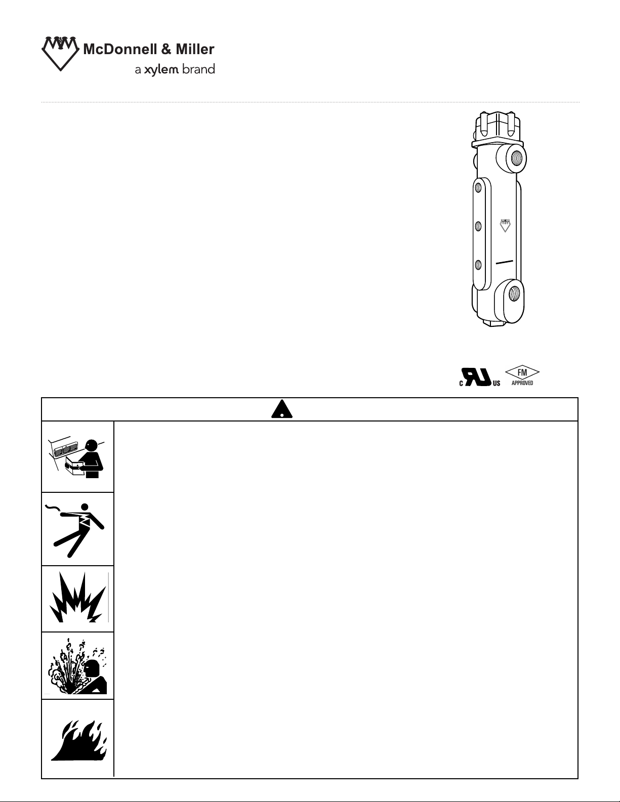
Series 750B-C3 Chamber
with 3 Probes
Series 750B-C4 Chamber
with 4 Probes
Features
• Cast Iron Body
• Sight Glass Tappings
• Gage Cock Tappings
• Stainless Steel Probes
• NEMA 4X Electrical Enclosure
• 250 psi Maximum Working Pressure
Designed for use with the Series 750B remote
mount control module to make a complete system
for level control in a boiler or other vessel.
INSTRUCTION MANUAL
MM-251C
Remote Chamber
WARNING
!
• Before using this product read and understand instructions.
TION
U
CA
G
IN
RN
A
W
• Save these instructions for future reference.
• All work must be performed by qualified personnel trained in the proper application,
installation, and maintenance of plumbing, steam and electrical equipment and/or systems in
accordance with all applicable codes and ordinances.
• To prevent serious burns, the boiler must be cooled to 80˚F (27˚C) and the pressure must
be 0 psi (0 bar) before servicing.
• To prevent electrical shock, turn off the electrical power before making electrical
connections.
• This low water cut-off must be installed in series with all other limit and operating controls
installed on the boiler. After installation, check for proper operation of all the limit and
operating controls, before leaving the site.
• To prevent serious personal injury from steam blow down, connect a drain pipe to the
control opening to avoid exposure to steam discharge.
• To prevent a fire, do not exceed the switch contact rating.
California Proposition 65 warning! This product contains chemicals known to the
•
state of California to cause cancer and birth defects or other reproductive harm.
Previous controls should never be installed on a new system. Always install new
•
controls on a new boiler or system.
!
Failure to follow this warning could cause property damage, personal inj ury or death.
CAUTION:
•
A more frequent replacement interval may be necessary based on the condition of
the unit at time of inspection. McDonnell Miller s warranty is one (1) year from date
of installation or two (2) years from the date of manufacture.
&
'
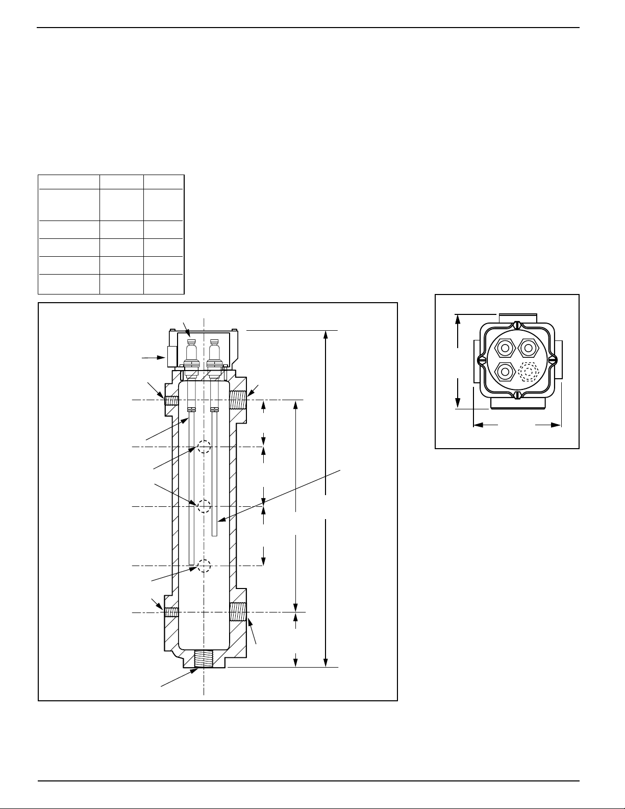
4-3/16"
(106.4)
4-3/8"
(111)
A
B
C
D
2-1/2"
(63.5)
3-1/4"
(82.5)
3-1/4"
(82.5)
3-1/8"
(79.4)
1" NPT
11-1/2"
(292)
18-5/8"
(473)
1/2" NPT
1/2" NPT
1/2" NPT
CONDUIT
CONNECTION
1"
NPT
1" NPT
1/2" NPT
ELECTRODE
PRE-CUT
9" PROBE ROD
CUT AS
NEEDED
SPECIFICATIONS
Maximum Water Temperature: 406˚F (208˚C)
Maximum Water Pressure: 250 psi (17.6 kg/cm
Maximum Steam Pressure: 250 psi (17.6 kg/cm
All probes are cut to 9" length (229mm). Any of these probes can
be used as the low water cut-off level probe. The remaining
probes can be ‘cut to length’ in the field using a metal cutting saw
to achieve desired pump control or additional alarm activation.
C3 C4
No. of 3 4
Probes
AXX
BXX
CXX
DX
2
)
2
)
INSTALLATION –
TOOLS NEEDED:
One (1) pipe wrench, one (1) flathead screwdriver and/or 11/32" nut driver,
one (1) metal-cutting saw, and pipe sealing compound.
2

CUT-OFF
LEVEL
Pump Off
Pump On
Burner Off
LOWER
EQUALIZING
LINE
2-5/16" (6mm)
Chamber
If the control will be the primary low water fuel
cut-off, size the steam (top) and water (bottom)
equalizing pipe lengths so that the cut-off level
mark is 11/2” (38mm) below the boiler’s normal
water level, but not lower than the lowest safe
permissible water level, as determined by the
boiler manufacturer.
OR
If the control will be the secondary low water
fuel cut-off, size the steam (top) and water (bottom)
equalizing pipe lengths so that the cut-off level
mark is at or above the lowest safe permissible
water level, as determined by the boiler
manufacturer.
Probes and Electrical Connections
• Each probe is made up of an electrode and a probe rod. Each
probe rod must be cut to an appropriate point of operation.
• A 9" rod will be positioned at the low water cut-off level.
Cut other rods for the pump operating probes to the desired
length.
• After cutting, secure the probe rod to the electrode and lock
the thread using the jamnut in the electrode sleeve. Insert the
probe into the chamber and tighten by hand. Then torque to
22-25 ft/lbs (30-34 N/m).
IMPORTANT: Do not use PTFE tape or hardening type
thread sealant. Use of pipe dope or hi-temp boiler grease
is recommended.
• Refer to and follow all local codes and standards.
• Secure the electrical enclosure to the chamber with gasket
between. Note that the electrical connection opening can be
orientated in any of 4 positions. Tighten screws to 30 - 35 in/lbs
(3.4-4.0 N/m).
•
Probe wire and conduit connections should be made following
accepted electrical practices.
NOTE
Wire must be 18 AWG stranded with glass braided silicone jacket
(UL 3071) suitable for high temperature (200˚C) service.
• Install electrical cover enclosure after making all connections
and after control has been tested for proper operation.
Tighten screws to 30 - 35 in/lbs (3.4-4.0 N/m).
3

MAINTENANCE
SCHEDULE:
• Blow down control as follows when boiler is
in operation.
Daily if operating pressure is above 15 psi (1 bar)
–
–
Weekly if operating pressure is below 15 psi (1 bar)
NOTE: More frequent blow-down may be necessary due to dirty boiler water and/or local codes.
• Remove and inspect probes annually. Replace
probes if they are worn, corroded or have an
excessive coating of scale or rust.
• Inspect the chamber and equalizing piping
annually. Remove all sediment and debris.
When blowing down a control at pressure, the blow
down valve should be opened slowly. The piping
needs to be warmed up and stagnant water in the
drain piping needs to be pushed out. Suddenly
opening a blow down valve causes steam to condense, which creates water hammer. Damage to
components can occur when water hammer occurs
due to improper blow down piping.
For these reasons, McDonnell & Miller recommends
a dual valve blow-down system for each control.
Proper Blow-down Procedure:
(Using dual valve system)
1. With water in the boiler at its normal level, open
“Positive Shut-off Ball Valve”.
2. Open “Throttling Gate Valve” slowly until drain
piping heats up and then open fully. Observe that
the water level starts falling in the gauge glass.
3. Close “Throttling Gate Valve” after verifying that
the pump contacts have closed and the burner
contacts have opened thus shutting down the boiler.
Note: If this does not happen, immediately close
all valves, turn off burner and correct the problem.
4. Close “Positive Shut-off Ball Valve”.
5. Observe that the water level returns to its normal
level before leaving site.
Replace probe every 10 years.
•
replacement of the probe is required if it is
where
significant water treatment is
cation with
Clean probe by wiping with non-abrasive cloth and
rinsing with clean water.DO NOT use sharp instruments
to remove any accumulations of rust or scale.
high make-up water requirements.
NOTE
!
More frequent
used in locales
required, or in appli-
BALL VALVE
GATE VALVE
Replace Probe if:
•
PFA insulator is cracked or worn.
Probe is loose.Failure to follow this caution could
•
cause property damage,personal injury or death.
Replace the control every 15 years.
•
To prevent serious personal injury from steam
DUAL
VALVES
FOR
BLOW
DOWN
Xylem Inc.
8200 N. Austin Avenue
Morton Grove, Illinois 60053
Phone: (847) 966-3700
Fax: (847) 965-8379
www.xyleminc.com/brands/mcdonnellmiller
McDonnell & Miller is a trademark of Xylem Inc. or one of its subsidiaries.
© 2013 Xylem Inc. MM-251C July 2013 Part No. 210016
pipe blow down, connect a drain pipe to the
control opening to avoid exposure to steam
discharge.
Failure to follow this caution could cause
personal injury.
CAUTION
!
CAUTION
CAUTION
!
!
 Loading...