

WARNI
NG
C
A
U
T
I
O
N
!
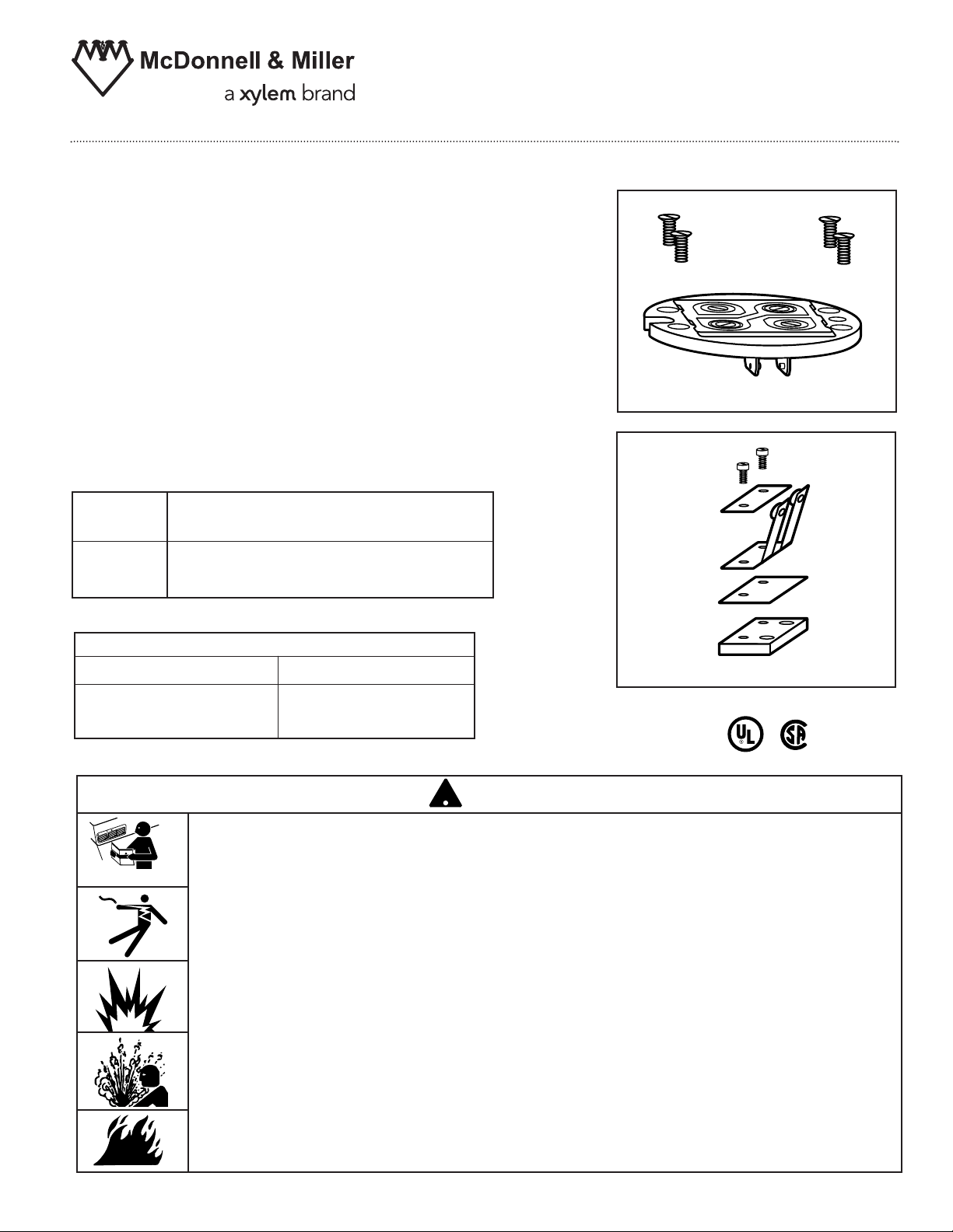
Replacement Pump and Burner
Switch Arm Contacts with
Terminal Panel
SA91-30B
SA91-30P
INSTRUCTION MANUAL
MM-714C
For installation on 5, 5-M, 7B or 7B-M
Switch Assemblies
Electrical Ratings
Models with 5 or 5-M Switch
Pump and Burner Switch Contact Ratings
Voltage Pilot Duty Only
120 VAC
345 VA
240 VAC
Models with 7B or 7B-M Switch
Switch Ratings
Burner Valve
120 VAC
345 VA 0 - 135 ohms @ 24 VAC
240 VAC
Terminal Panel
Switch Arm Contact
WARNING
• Before using this product read and understand instructions.
• Save these instructions for future reference.
• All work must be performed by qualified personnel trained in the proper
application, installation, and maintenance of plumbing, steam, and electrical
equipment and/or systems in accordance with all applicable codes and ordinances.
• To prevent a fire, do not exceed the switch contact rating.
Failure to follow this warning could cause property damage, personal injury or
death.
O
FF
O
N
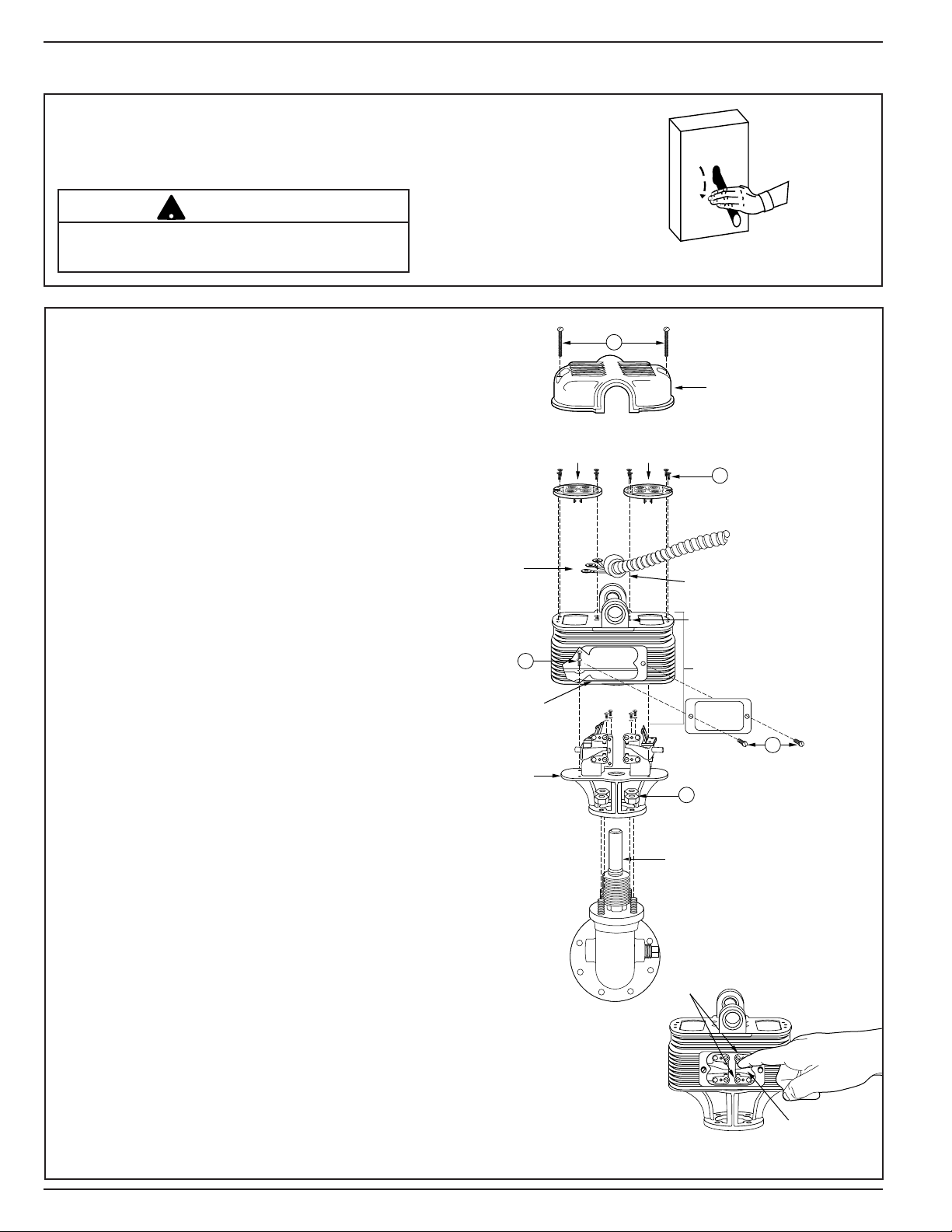
STEP 1 - Removal and Replacement of Contacts and Terminal Panels
BURNER
SWITCH
LEVER
STOPS
A
C
E
TOWER
TUBE
FITTIN
G
H
U
B
S
WITC
H
H
O
U
S
IN
G
T
E
RMINA
L
CO
NNE
CT
IO
NS
S
WIT
C
H
C
O
V
E
R
P
U
MP
T
E
R
MIN
A
L
P
A
N
E
L
B
U
R
N
E
R
T
E
R
MIN
A
L
P
A
N
E
L
C
O
N
D
U
I
T
C
O
N
N
E
C
T
O
R
N
AM
EPLAT
E
NA
ME
P
L
A
TE
BASE
PLAT
E
B
D
!
a. Turn power off to boiler and all controls.
Allow boiler to cool to 80˚F (27˚C) and
reduce the pressure to 0 psi (0 bar).
CAUTION
There may be more than one source of power to
the boiler.
b. Remove Switch Assembly, Terminal
Panels and Switch Housing
• Remove two screws (A) and lift off switch
cover.
• Identify terminal connections for rewiring
and then disconnect all wires from terminal
panels.
• Remove conduit connector and wire from
integral fitting hub.
• Remove four hex nuts (B) and carefully lift
switch assembly up and off tower tube.
• Remove two screws (C) and remove
nameplate.
• Loosen and remove four screws (E) that
hold pump and burner terminal panels in
place. Do not remove terminal panels at
this time.
• Reach through nameplate opening and hold
burner switch lever about midway
between upper and lower stops to move
contact arms into correct (upright) position.
With contact arms in upright position, carefully
remove burner terminal panel.
• Reach through nameplate opening and hold
pump switch lever about midway
between upper and lower stops to move
contact arms into correct (upright) position.
With contact arms in upright position, carefully
remove pump terminal panel.
• Loosen four screws (E) and carefully lift
switch housing up off base plate.
2

NOTCH
NOTCH
5 / 5-M
TERMINAL PANEL
ORIENTATION
24
1
BLUE RED
3
31
42
A
C
E
TOWER
TUBE
FITTIN
G
H
U
B
S
WITC
H
H
O
U
S
IN
G
T
E
RMINA
L
CO
NNE
CT
IO
NS
S
WIT
C
H
C
O
V
E
R
P
U
MP
T
E
R
MIN
A
L
P
A
N
E
L
B
U
R
N
E
R
T
E
R
MIN
A
L
P
A
N
E
L
C
O
N
D
U
I
T
C
O
N
N
E
C
T
O
R
N
AM
EPLAT
E
NA
ME
P
L
A
TE
BASE
PLAT
E
B
D
F
G
H
I
c. Remove and Replace Switch Arm Contacts
• Remove two screws (F) and lift off bus bar
(G), contact arms (H) and insulator (I).
• Place new insulator (I), contact arms (H) and
bus bar (G) in position and fasten with two
screws (F). Make sure the contact arm blades (H)
are in alignment and at right angle to insulator.
d. Replace Switch Housing, Switch
Assembly and Reconnect Wiring
• Replace switch housing and fasten to
base plate with four screws (E).
Move burner switch arms to upright position
•
by reaching through nameplate opening
and holding burner switch lever midway
between stops. Carefully set burner
terminal panel in position and fasten with
screws (D). Do not force. (See diagram at
lower right for proper orientation of
terminal panel).
Move pump switch arms to upright position
•
by reaching through nameplate opening
and holding pump switch lever midway
between stops. Carefully set pump
terminal panel in position and fasten with
screws (D). Do not force. (See diagram
at lower right for proper orientation of
terminal panel).
• Check visually to see that contact arms
are in proper position between terminal
panel contacts and move lever up and
down to see that switch operates freely
and smoothly.
• Carefully slide switch assembly over
tower tube and secure with four hex
nuts (B).
• Install conduit connector and wires to
the integral fitting hub on switch
assembly.
• Reconnect wiring to terminal panel in
exactly the same position as removed.
• Replace switch cover and fasten with
two screws (A).
• Replace nameplate and fasten with
two screws (C).
Proceed to Step 2 to Test Control
3

!
!
McDonnell & Miller
STEP 2 - Testing
– Dimensions shown are typical.
– The following testing procedure is only meant to serve as a verification of proper
operating sequence.
a. Turn on power to boiler and pump circuits.
With the boiler empty, the pump should turn on (5 or 5-M switch models) or the valve open
(7B or 7B-M switch models). The burner should remain off and boiler should begin to fill with water.
CAUTION
mmediately turn off all power if the burner turns on with no water in the gauge glass.
I
Investigate further before continuing procedure.
b. For Automatic Reset Models
When water level in the gauge glass is approximately 1 3/8” (35mm) above the horizontal cast line,
the burner should turn on.
For Manual Reset Models
When water level in the gauge glass is approximately 1 3/8” (35mm) above the horizontal cast line,
press the manual reset button and the burner should turn on.
c. For 5 or 5-M Switch Models
When water level in the gauge glass is approximately 2 1/8” (54mm) above the horizontal cast line,
the pump should turn off.
For 7B or 7B-M Switch Models
When water level in the gauge glass is approximately 2 11/16” (68mm) above the horizontal cast
line, the valve should be closed.
CAUTION
If pump does not turn off or valve close, turn off water supply to boiler. Investigate
further before continuing procedure.
d. With the water in the boiler at its normal level and burner on, SLOWLY open the blow-down valve
until it is fully open. As the water level in the gauge glass begins to drop, verify that the following
occurs.
For 5 or 5-M Switch Models
When water level drops to approximately 1 1/8” (29mm) above the horizontal cast line, the pump
should turn on.
When water level drops to the horizontal cast line, the burner should turn off.
For 7B or 7B-M Switch Models
As the water level drops, the valve should begin to open.
When the water level drops to approximately 7/8” (22mm) above the horizontal cast line, the valve
should be full open.
When the water level drops to the horizontal cast line, the burner should turn off.
e. Close the blow-down valve after burner turns off and restore water level to normal operating level.
f. Repeat testing procedure several times to ensure proper operation of control.
g. After testing and verification of control operation, the boiler can be returned to service.
Xylem Inc.
8200 N. Austin Avenue
Morton Grove, Illinois 60053
Phone: (847) 966-3700
Fax: (847) 965-8379
www.mcdonnellmiller
McDonnell & Miller is a trademark of Xylem Inc. or one of its subsidiaries.
© 2013 Xylem Inc. MM-714C January 2013 Part No. 210422
 Loading...