

INSTRUCTION MANUAL
MM-702F
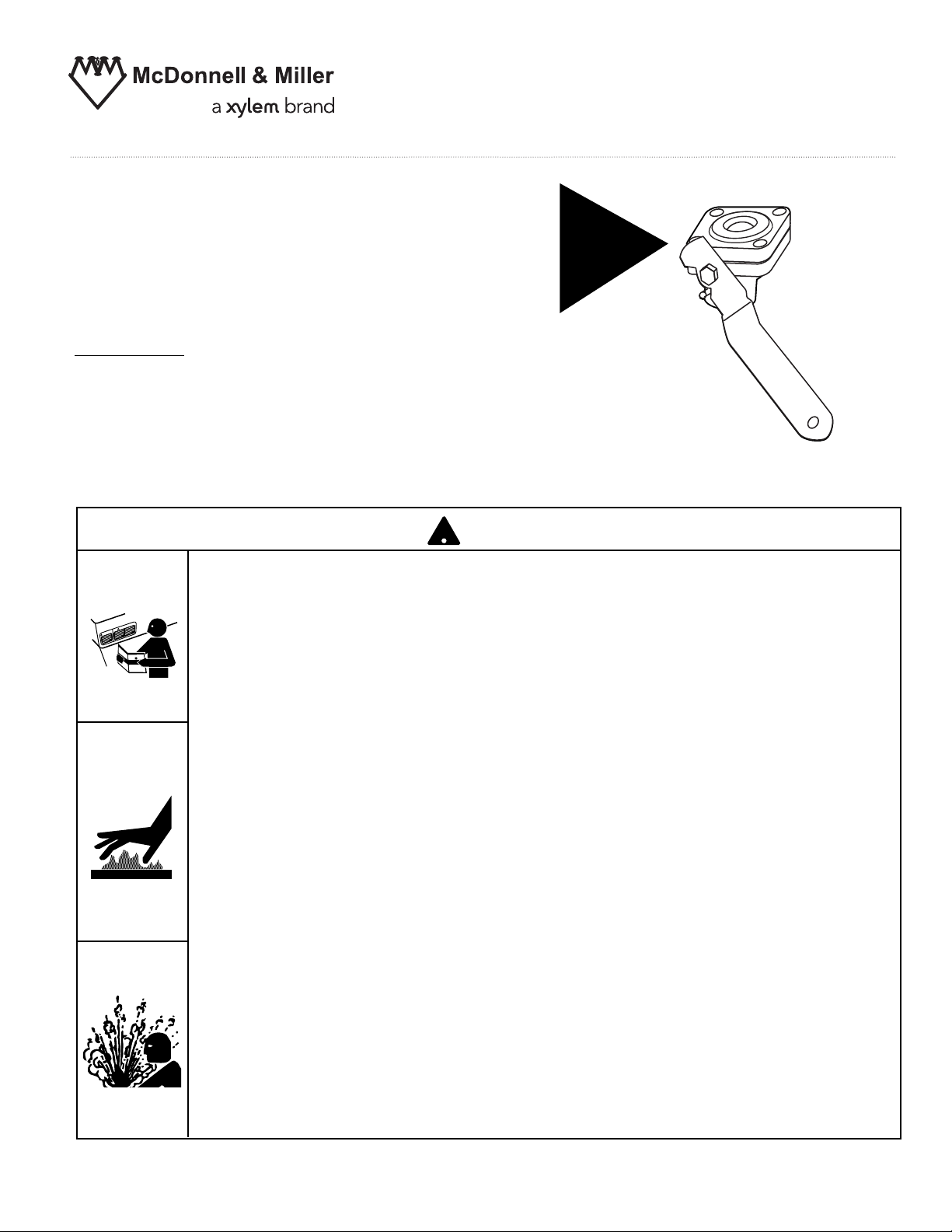
Series 14-B Ball Type
Blow Down Valve
Applications:
For Series 47, 67, and 70 boiler control blow
down valve replacement.
• Before using this product read and understand instructions.
N
TIO
U
A
C
NING
R
A
W
• Save these instructions for future reference.
• All work must be performed by qualified personnel trained in the proper application, installation, and maintenance of plumbing, steam, and electrical equipment and/or systems in
accordance with all applicable codes and ordinances.
WARNING
!
EASY
OPEN
HANDLE!
Series 14-B
• To prevent serious burns, wear heat resistant gloves when opening and closing valves, or
handling hot equipment.
• To prevent serious burns, allow the control and surrounding equipment to cool to 80˚F
(27˚C) and allow pressure to release to 0 psi (0 bar) before servicing.
• When flushing control (blow down), hot water and steam will flow out. To prevent serious
personal injury, connect a drain pipe to the control opening to avoid exposure to steam
discharge.
To prevent flooding,do not puncture float.
•
California Proposition 65 warning! This product contains chemicals known to the
•
•
!
state of California to cause cancer and birth defects or other reproductive harm.
Previous controls should never be installed on a new system. Always install new
•
controls on a new boiler or system.
Failure to follow this warning could cause property damage, personal inj ury or death.
CAUTION:
•
A more frequent replacement interval may be necessary based on the condition of
the unit at time of inspection. McDonnell Miller s warranty is one (1) year from date
&
'
of installation or two (2) years from the date of manufacture.
2
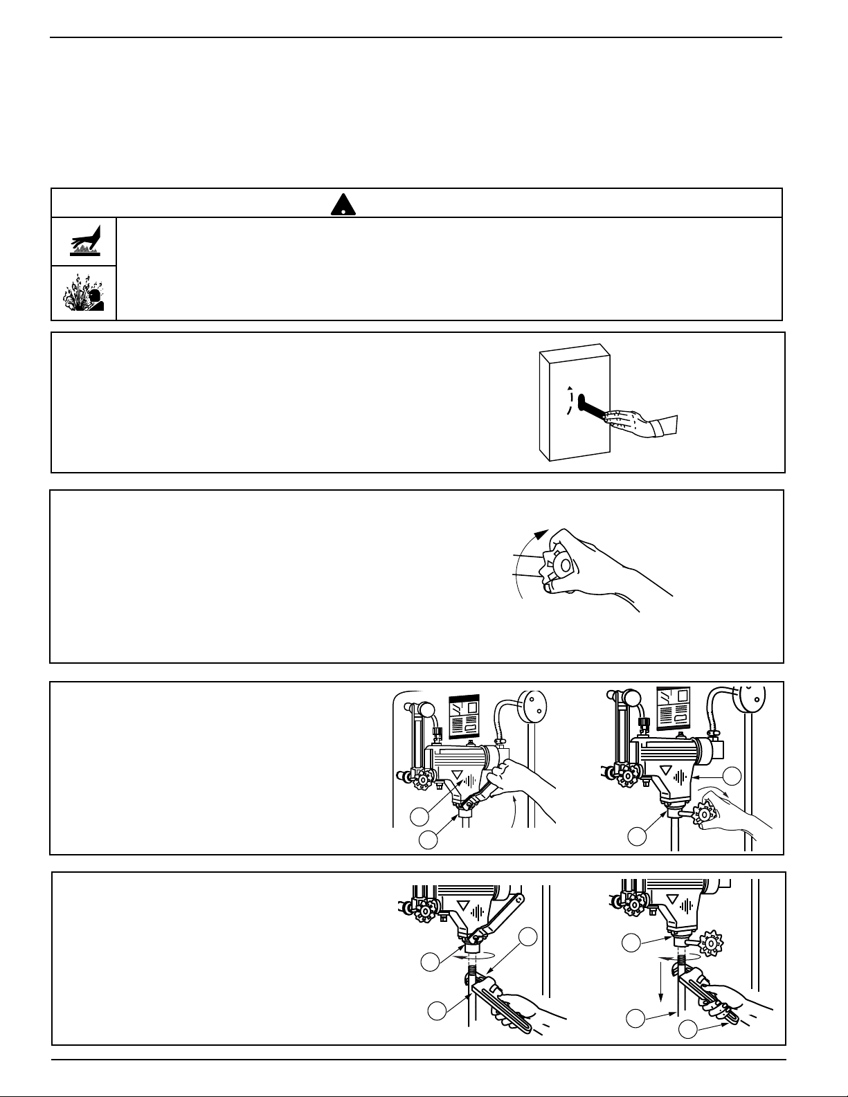
b. Shut off the inlet water supply by closing the make
up water feed valve.
c. Open the blow down valve (D). Drain
the control (A) to a point where no additional water can enter the control. Let
the control (A) and surrounding equipment to cool to 80˚F (27˚C) and allow
pressure to release to 0 psi (0 bar).
A
D
A
D
d. Using a pipe wrench (B), remove the
blow down pipe (C) from the existing
blow down valve (D).
B
D
C
C
D
B
STEP 1 - Preparation
INSTALLATION –
TOOLS NEEDED:
One (1) flathead screwdriver, one (1) scraper, one (1) pipe
wrench, one (1) hammer, and pipe sealing compound.
a. Shut off the boiler and disconnect the power to the
entire boiler system.
OFF
ON
OR
OR
To prevent serious burns, wear heat resistant gloves when opening and closing valves, or handling hot
equipment.
To prevent serious burns, allow the control and surrounding equipment to cool to 80˚F (27˚C) and allow
pressure to release to 0 psi (0 bar) before servicing.
Failure to follow this caution could cause personal injury.
!
CAUTION
3
h. Using a scraper, remove the old gasket (F)
from the control (A). The gasket sealing surface (G) must be smooth and clean for
proper installation.
G
F
A
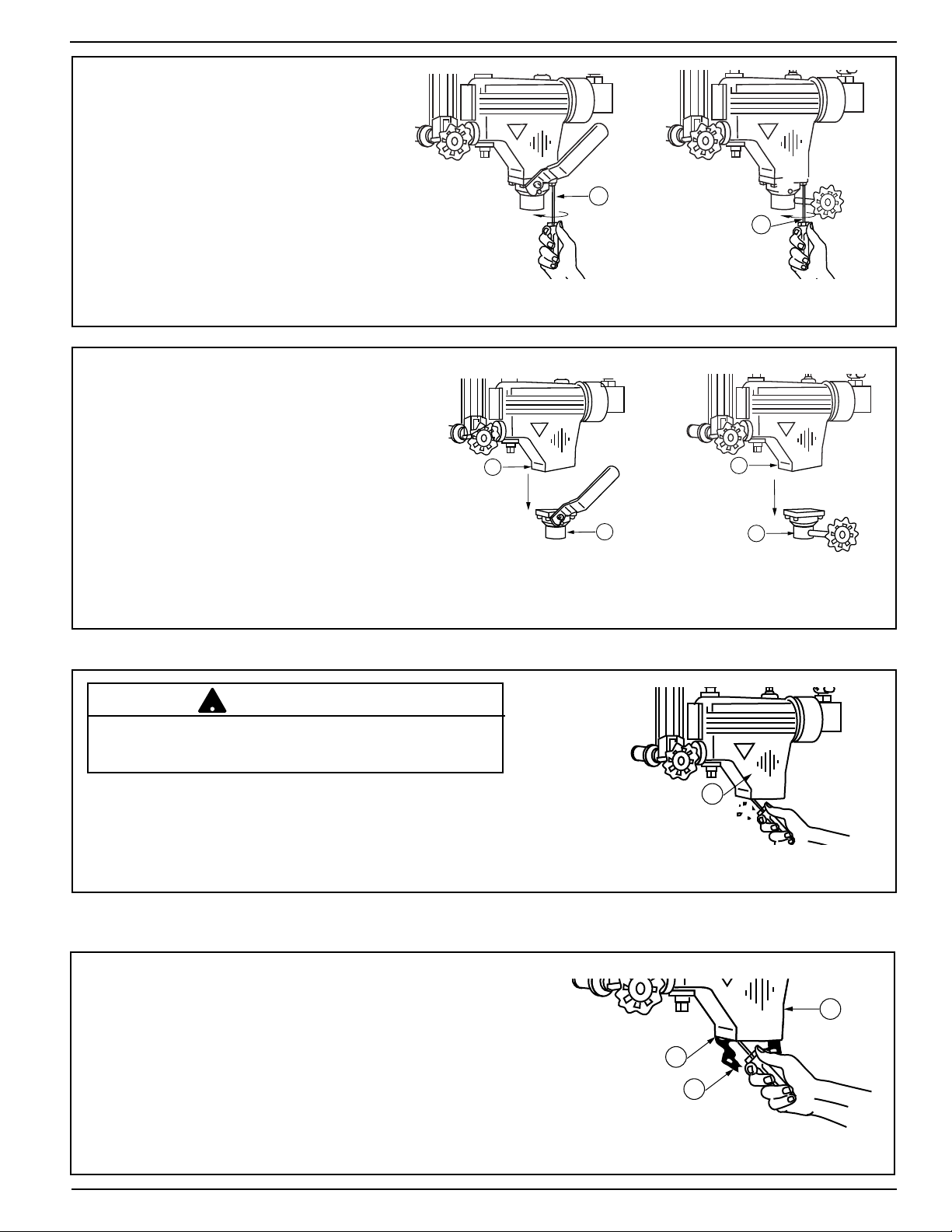
e. Using a flathead screwdriver (E),
loosen the four (4) screws.
E
E
f. Remove the blow down valve (D) from
the control (A). If necessary, use a
hammer to tap it loose.
D
D
A
A
g. Inspect the float chamber (E) for debris.
Carefully remove any debris, mud, or other foreign matter which may obstruct the float's full
range of motion, without puncturing the float.
E
OR
OR
To prevent flooding, do not puncture float.
Failure to follow this caution could cause property damage.
!
CAUTION
NOTE: For spring type blow down
valves, the spring mechanism must
be removed from the control body.

4
H
CLOSED
OPEN
G
K
STEP 2 - Installing the New Blow Down Valve
a. Hold the new replacement blow down
valve (H) upright and remove the rubber
band around the valve body.
Be careful not to tip the valve as its
components might fall out. If this
occurs, reassemble as shown (J).
H
Gasket
PTFE Seal
PTFE Seal
Spring
Ball
Housing
J
b. Position the blow down valve (H) onto the control's
mating surface (G). So that it's handle (K) is accessible and is able to swing through its full range of
motion (90˚).
c. Insert the four (4) screws provided through the blow
down valve and gasket (D) into the threaded holes
on the mating surface (G).
G
D
d. Using a flathead screwdriver (L), tighten the screws
to approximately 15 ft•lb (20 N•m).
L

5
e. Verify that the blow down valve (H) is unobstructed
by opening and closing the valve over its full range
of motion (90˚).
f. Apply pipe sealing compound to the threaded end of
a 3/4" (20mm) NPT blow down pipe (M) and screw it
into the control (N). Tighten the pipe (M) with a pipe
wrench (P) to approximately 47 ft•lb (64 N•m).
M
P
N
g. Turn the blow down valve handle (K) to its closed
position.
K
CLOSED
h. Hang the enclosed blow down card (Q) as close to
the control as possible, or remove the protective
backing and affix the card on the boiler jacket close
to the control.
Q
H

6
IMPORTANT: The burner must not turn on until the water
level has reached its minimum safe operating level as determined by the boiler manufacturer. If the burner turns on
before this point, immediately shut off the boiler and correct
the problem. Other equipment may be involved and the system should be inspected by qualified personnel.
d. Verify that the burner is off and that the system is filling
with water by observing the water level rise in the
gauge glass(R)
R
STEP 3 - Testing
a. Make sure that the blow down valve handle (K) is in
its closed position.
K
CLOSED
b. Open the make-up water feed valve.
c. Turn on the power to the boiler system and turn on
the boiler.
OFF
ON

7
To prevent serious personal injury from steam blow down, connect a drain pipe to avoid exposure to steam
discharge.
Failure to follow this caution could cause personal injury or death.
!
WARNING
IMPORTANT: If the control (A) does not blow down
and/or the burner does not shut-off, close the blow
down valve (H), immedialety shut off the boiler, and
correct the problem. Other equipment may be involved
and the system should be inspected by qualified personnel.
e. Allow the system to build to its normal operating pres-
sure and check for leakage around the mating surface
(G), the shaft (S), and the pipe opening (T).
1.
If leakage occurs around the mating surface (G),
retighten the four (4) screws. If leakage continues,
follow "Step 1" to remove the blow down valve (H).
Closely following the installation instructions, replace it.
2.
If leakage occurs around the valve shaft (S),
follow
"Step 1" to remove the blow down valve (H). Closely
following the installation instructions, replace it.
3.
If leakage occurs around the pipe outlet (T),
follow
"Step 1" to remove the blow down valve (H) and
verify that it has been properly assembled as shown
in "Step 2-a". Inspect the blow down valve (H) for
debris which may prevent it from completely closing
or sealing. If leakage continues, follow "Step 1" to
remove it. Closely following the installation instructions, replace the blow down valve (H).
T
GSG
H
f. Open the blow down valve (H) to "blow down" the
control (A). The burner should shut-off.
A
H
g. Close the blow down valve (H) and check for
leakage by following the instructions in "Step 3"
section e.
H
INSTALLATION COMPLETE

MAINTENANCE
SCHEDULE:
• Blow down weekly when the boiler is
in operation.
• Disassemble and inspect annually. Replace
the control if it is worn, corroded, or if components no longer operate properly.
• Inspect the float chamber and equalizing
piping annually. Remove all sediment
and debris.
• Replace the blow down valve every 10 years.
More frequent replacement may be required
if it is used in locales where significant water
treatment is required, where more frequent
cleaning is necessary, or in applications with
high make-up water requirements.
PROCEDURE:
CAUTION
!
To prevent serious personal injury from steam
pipe blow down, connect a drain pipe to avoid
exposure to steam discharge.
Failure to follow this caution could cause
personal injury.
1. Blow down the low water cut-off when the
water level is at its normal level and the burner
is on. Slowly open the blow down valve until it
is fully open and observe the water level fall in
the gauge glass. Close the valve after verifying
that the burner shuts off. If this does not
happen, immediately shut off the boiler and
correct the problem.
Xylem Inc.
8200 N. Austin Avenue
Morton Grove, Illinois 60053
Phone: (847) 966-3700
Fax: (847) 965-8379
www.xyleminc.com/brands/mcdonnellmiller
McDonnell & Miller is a trademark of Xylem Inc. or one of its subsidiaries.
© 2013 Xylem Inc. MM-702F July 2013 Part No. 210286
 Loading...