

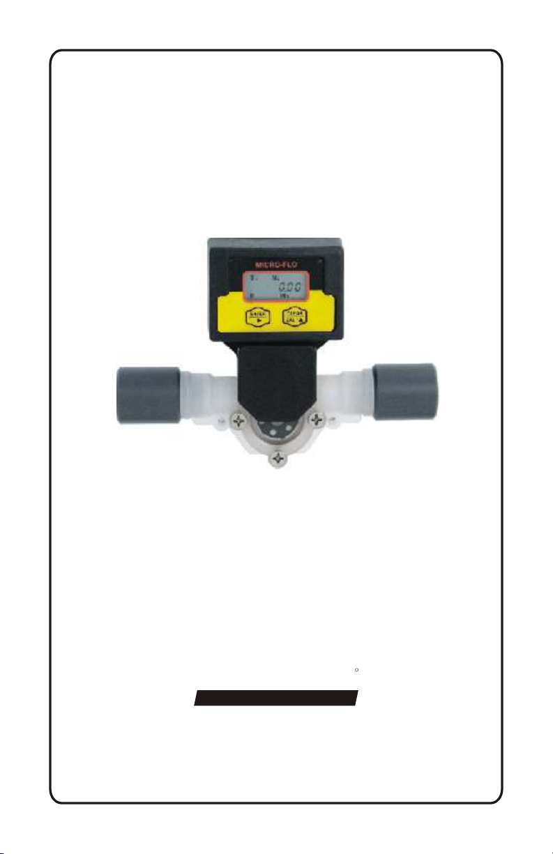
MICRO-FLO
MICRO-FLO
Digital Paddlewheel Flow meter
Operating Manual
R
Blue-White
Industries, Ltd.
5300 Business Drive
Huntington Beach, CA 92649
Phone: 714-893-8529 FAX: 714-894-9492
E mail: sales@blue-white.com or techsupport@blue-white.com
Website: www.blue-white.com
USA

MICRO-FLOPage 2
TABLE OF CONTENTS
1.....Introduction....................................................................................2
2.....Features .............................................................. .............. ..............3
3.....Model number matrix ............ .............. .............. .............. ..............3
4.....Specifications ............ .............. .............. .............. .............. ..............4
4.1..Temperature and pressure limits...... .............. .............. ..............4
4.2..Dimensions ................................................... .............. ..............5
4.3..Replacement parts ........................... .............. .............. ..............5
5.....Installation.. .............. .............. .............. .............. .............. ..............6
5.1..Wiring connections ...................................................................6
5.2..Circuit board connections . ........................................................6
5.3..Flow verification output signal..................................................6
5.4..Panel or wall mountings............................................................7
6.....Operation.... .............. .............. .............. .............. .............. ..............7
6.1..Theory of operation...................................................................7
6.2..Control panel ...... .............. .............. ..........................................8
6.3..Flow stream requirements . .............. .............. .............. ..............8
6.4..Run mode display............................ .............. .............. ..............8
6.5..Run mode operation ..................................................................9
6.6..Viewing the K-factor......... .............. .............. .............. ..............9
7.....Programming............ .............. .............. .............. .............. ..............9
7.1..Field Calibration ............... .............. .............. .............. ..............9
7.2..Programming for body size/range S1 - S6 ..... .............. ..............10
7.3..Field calibration range setting S0 ..............................................11
Warranty information.......................... .............. .............. ..............12
1.0 Introduction
The Micro-Flo flowmeter is designed to display flow rate and flow total on
a six digit LCD display. The meter can measure bi-directional flows in
either vertical or horizontal mounting orientation. Six flow ranges and four
optional pipe and tubing connections are available. Pre-programmed
calibration K-factors can be selected for the corresponding flow range or a
custom field calibration can be performed for higher accuracy at a specific
flow rate. The meter is factory programmed for the correct K-factor of
the body size included with the meter.
MICRO-FLO
2.0 Features
!
Four connection options available:
1/8” F/NPT, 1/4” F/NPT, 1/4” OD x .170 ID Tubing & 3/8” OD x 1/4”
ID Tubing sizes.
!
Six body size/flow range options available:
30 to 300 ml/min, 100 to 1000 ml/min, 200 to 2000 ml/min,
300 to 3000 ml/min, 500 to 5000 ml/min, 700 to 7000 ml/min.
!
3 model display variations:
FS = Sensor mounted display
FP = Panel mounted display (includes 6’ cable)
FV = No display. Sensor only. 5vdc current sinking output
!
6 digit LCD, up to 4 decimal positions.
!
Displays both rate of flow and total accumulated flow.
!
Open collector alarm setpoint.
! User selectable or custom programmable K-factor.
Flow units: Gallons, Liters, Ounces, milliliters
Time units: Minutes, Hours, Days
! Volumetric field calibration programming system.
! Non-volatile programming and accumulated flow memory.
! Total reset function can be disabled.
! Clear PVC viewing lens or PVDF chemical resistant lens.
! Weather resistant Valox PBT enclosure. NEMA 4X
Page 3
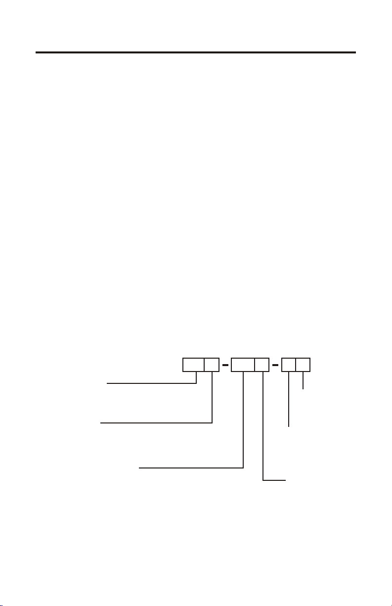
3.0 Model number matrix
METER FUNCTION
FS = Flow rate and Totalizing. On-sensor mounting
FP = Flow rate and Totalizing. Remote panel mounting
FV = Flow sensor only (no display)
POWER SUPPLY
1 = Transformer U.S. 115VAC/15VDC
2 = Transformer E.U. 220VAC/15VDC
3 = Transformer U.S. 230VAC/15VDC
None = No selection (customer supplied)
FLOW RANGE SELECTION
10 = 30-300 ml/min
20 = 100-1000 ml/min
30 = 200-2000 ml/min
40 = 300-3000 ml/min
50 = 500-5000 ml/min
60 = 700-7000 ml/min
O-RING SEAL
V = Viton
E = EPDM
CONNECTOR
4 = .250” OD tubing PVDF
5 = .125” Female NPT PVC
6 = .375” OD tubing PVDF
7 = .250” Female NPT PVC
LENS MATERIAL
0 = Clear PVC
1 = Opaque PVDF

MICRO-FLOPage 4
4.0 Specifications
Max. Working Pressure:
PVC lens, 130 psig (9 bar) @ 70 F (21 C)
PVDF lens, 150 psig (10 bar) @ 70 F (21 C)
Max. Fluid Temperature:
PVC lens, F/NPT connectors 130 F (54 C) @ 0 PSI
PVDF lens, tubing connectors 200 F (93 C) @ 0 PSI
oo
oo
Full scale accuracy +/- 6%
Input Power requirement: 9 - 28 VDC
Sensor only output cable: 3-wire shielded cable, 6ft
Pulse output signal: Digital square wave (2-wire) 25ft max.
Voltage high = 5Vdc,
Voltage low < .25Vdc
50% duty cycle
Output frequency range: 4 to 500Hz
Alarm output signal: Open collector. Active low above
programmable rate set point.
30Vdc maximum, 50mA max load.
Active low < .25Vdc
Enclosure: NEMA type 4X, (IP56)
Approximate shipping wt: 1 lb. (.45 kg)
oo
oo
4.1 Temperature and Pressure limits
Maximum Temperature vs. Pressure
oo
200 F (93 C)
oo
174 F (79 C)
oo
148 F (64 C)
oo
122 F (50 C)
TEMPERATURE
oo
96 F (36 C)
oo
70 F (21 C)
Models with
PVC Lens or connectors
0 30(2) 60(4) 90(6) 120(8) 150(10)
STATIC PRESSURE PSI (BAR)
Models with
PVDF Lens and connectors

4.2 Dimensions
5.00 in
[127 mm]
Page 5MICRO-FLO
2.22 in
[56.26 mm]
1.48 in
[37.71 mm]
3.51 in
[89.03 mm]
4.3 Replacement Parts
20
13
10
9
5
1
14
22
6
7
4
3
2
18
16
17
15
Key Part No. Description Qty.
1 90011-081 Screw 6-32x.50 Phil Flt SS 4
2 90002-227 Lens Cap Clear PVC 1
90002-228 Lens Cap Opaque PVDF 3
90003-143 O-Ring Viton 1
90003-146 O-Ring EP
4 90002-230 Paddle PVDF 1
8
5 90007-592 Axle PVDF 1
6 90003-012 O-Ring Viton 2
90003-011 O-Ring EP
7 76001-300 Body S1 PVDF (30-300ml/min) 1
76001-301 Body S2 PVDF(100-1000ml/min)
76001-302 Body S2 PVDF (200-2000ml/min)
76001-303 Body S2 PVDF (300-3000ml/min)
76001-304 Body S2 PVDF (500-5000ml/min)
76001-305 Body S2 PVDF (700-7000ml/min)
8 90011-113 Screw #4x.50 Phil Blk 4
9 76000-137 Adapter .250 F/NPT PVC 2
8
21
76000-456 Adapter .125 F/NPT PVC
90002-038 Adapter .37OD x .25ID Tube PVDF
90002-042 Adapter .25OD x .17ID Tube PVDF
10 90012-252 Sensor 1
13 90002-242 Enclosure, Valox 1
14 90012-254 LCD display 1
15 90010-260 Circuit board 1
16 90006-604 Gasket, rear enclosure 1
17 90002-243 Cover, enclosure rear 1
18 90008-199 Liquid Tight Connector Set 1
19 90011-178 Screw #4x.62 Phil SS Blk 4
20 90011-177 Screw #2x.25 L Phil St 2
21 76001-299 Tubing connector seal 1
22 90006-605 Gasket, sensor mount seal 1
19
PARTS LIST

5.0 Installation
5.1 Wiring Connections
On sensor mounted units, the output signal
wires must be installed through the back panel
using a second liquid-tite connector (included).
To install the connector, remove the circular
knock-out. Trim the edge if required. Install the
extra liquid-tite connector.
On panel or wall mounted units, wiring may be
installed through the enclosure bottom or
through the back panel. See below.
5.2 Circuit Board Connections
Programming disable jumper (un-installed).
Install on both pins to disable programming.
MICRO-FLOPage 6
KNOCK-OUT ½” diameter
Power Input
Rear view
Alarm output
Open Collector
30 VDC max
50mA max
Pulse output
Digital sq. Wave
5 VDC high
<.25 VDC low
50% duty cycle
(+)
(-)
(+)
(-)
CIRCUIT
BOARD
Front panel touch pad
ribbon cable connection
Power input (+ 9-28 Vdc)
Power input ( ground )
Sensor input (+) RED
Sensor input (signal) BARE
Sensor input ( - ) BLACK
5.3 Flow Verification Output Signal
When connected to external equipment such as a PLC, data logger, or BlueWhite metering pump, the pulse output signal can be used as a flow verification
signal. When used with Blue-White metering pumps, connect the positive (+)
terminal on the Micro-Flow circuit board to the pump’s yellow signal input wire
and the negative (-) terminal to the black input wire.

5.4 Panel or wall mounting
Wiring through enclosure
bottom for dry applications
Panel or wall
mounting screw
locations
Through panel wiring
for water resistant
applications
1.75 in
[45 mm]
Page 7MICRO-FLO
Recommended panel or
wall mounting cut-out
for wire connection opening
6.0 Operation
6.1 Theory of operation
The Micro-Flo flowmeter is designed to measure the flow rate and accumulate the total volume of a fluid. The unit contains a paddle wheel that has six
(6) through holes to allow infrared light to pass through, a light-detecting
circuit and a LCD-display electronic circuit.
As fluid passes through the meter body, the paddle wheel spins. Each time
the wheel rotates a DC square wave is output from the sensor. There are six
(6) compete DC cycles induced for every revolution of the paddle wheel.
The frequency of this signal is proportional to the velocity of the fluid in the
conduit. The generated signal is then sent into the electronic circuit to be
processed.
The meter is factory programmed for the correct K-factor of the body
size included with the meter.
The Micro-flo flowmeter includes the following features:
! Displays either the flow rate or the accumulated total flow.
! Provides a pulse output signal that is proportional to the flow rate.
! Provides an open collector alarm output signal. Active low at flow rates
above the user programmed value.
! Provides user selectable, factory preset calibration k-factors.
! Provides a field calibration procedure for more precise measurement.
! Front panel programming can be disabled by a circuit board jumper pin.
1.00 in
[25 mm]

MICRO-FLOPage 8
6.2 Control Panel
Enter Button (right arrow) -
! Press and release - Toggle between
Rate, Total, and Calibrate screens in
the run mode. Select program
screens in the program mode.
! Press and hold 2 seconds - Enter
and exit program mode. (Automatic
exit program mode after 30 seconds
of no inputs).
Clear/Cal (up arrow) -
! Press and release - Clear total in the run mode. Scroll through and Select
options in the program mode.
6.3 Flow stream requirements
! The Micro-flo flowmeter can measure fluid flow in either direction.
! The meter must be mounted so that the paddle axle is in a horizontal
position - up to 10 off the horizontal is acceptable.
! The fluid must be capable of passing infra-red light.
! The fluid must be free of debris. A 150 micron filter is recommended -
especially when using the smallest body size (S1), which has a 0.031”
through hole.
6.4 Run mode display
Body size/range
0 = Field calibrate
1 = 30-300 ml/min
2 = 100-1000 ml/min
3 = 200-2000 ml/min
4 = 300-3000 ml/min
5 = 500-5000 ml/min
6 = 700-7000 ml/min
Function indicator
R = Flow rate indicated
T = Flow total indicated
o
Cal
ML
S
1
SetP
RMin
Alarm indicator
SetP (steady) = active
SetP (flashing) = alarm
none = not programmed
Field Calibration indicator
Cal (steady) = active
Cal (flashing) = calibrating
none = factory cal. active
0
Display Value
Rate time base indicator
Min = Rate per minute
Hr = Rate per hour
Day = Rate per day
Flow units indicator
ML = Milliliters
OZ = Ounces
GAL = Gallons
LIT = Liters

6.5 Run mode operation
S
1
ENTER
RMin
S
1
ENTER
T
ML
ML
FLOW RATE DISPLAY - Indicates rate of flow, S1 = body size/range
#1, ML = units displayed in milliliters, MIN = time units in minutes, R
0
= flow rate displayed.
FLOW TOTAL DISPLAY - Indicates accumulated total flow, S1 =
body size/range #1, ML = units displayed in milliliters, T = total
0
accumulated flow displayed.
6.6 Viewing the K-factor (pulses per unit)
ML
s1
R Min
0
ENTER
CLEAR
While in the run mode, Press and hold ENTER then
CAL /
press and hold CLEAR to display the K-factor.
Page 9MICRO-FLO
s1
36245
ENTER
CLEAR
Release ENTER and CLEAR to return to run mode.
CAL /
7.0 Programming
The Micro-Flo flowmeter uses a K-factor to calculate the flow rate and
total. The K-factor is defined as the number of pulses generated by the
paddle per volume of fluid flow. Each of the six different body sizes have
different operating flow ranges and different K-factors. The meter is
factory programmed for the correct K-factor of the body size included
with the meter.
The meter’s rate and total displays can be independently programmed to
display units in milliliters (ML), ounces (OZ), gallons (GAL), or liters
(LIT). Rate and total can be displayed in different units of measure. The
factory programming is in milliliters (ML).
The meter’s rate display can be independently programmed to display time
base units in minutes (Min), Hours (Hr), or Days (Day). The factory
programming is in minutes (Min).
For greater accuracy at a specific flow rate, the meter can be field calibrated. This procedure will automatically over-ride the factory K-factor with
the number of pulses accumulated during the calibration procedure. The
factory default settings can be re-selected at any time.
7.1 Field Calibration
Any body size/range can be field calibrated. Calibration will take into
account your specific application’s fluid properties, such as viscosity and
flow rate, and increase the accuracy of the meter in your application.
The Body Size/Range must be set for “S0” to enable the calibration mode.
Follow the programming instructions on pages 10 & 11 to reset the Body
Size/Range and perform the calibration procedure.

MICRO-FLOPage 10
7.2 Programming for body size/ranges S1through S6 -
Press and Hold ENTER to initiate the programming mode.
S
1
ENTER
1
ENTER
R Min
2
ENTER
R Min
3
ENTER
RMin
1
ENTER
T
2
ENTER
T
3
RST Y
ENTER
T
1
ENTER
R SetP
ML
ML
ML
ML
ML
off
BODY SIZE/RANGE - Select your body size. Selected body size flashes.
CLEAR
Press and release to select. S1 > S2 > S3 > S4 > S5 > S6 > S0
CAL /
Note: Select S0 for field calibrating any body size range.
RATE UNIT OF MEASURE - current unit of measure setting flashes
CLEAR
0
0
0
0
0
Press and release to select. ML > OZ > GAL > LIT
CAL /
RATE DECIMAL LOCATION - current decimal display setting flashes.
CLEAR
Press and release to select. 0 > 0.0 > 0.00 > 0.000 > 0.0000
CAL /
RATE TIME BASE - current time base unit of measure setting flashes.
CLEAR
Press and release to select. Min > Hr > Day
CAL /
TOTAL UNIT OF MEASURE - current unit of measure setting flashes
CLEAR
Press and release to select. ML > OZ > GAL > LIT
CAL /
TOTAL DECIMAL LOCATION - current decimal display setting flashes.
CLEAR
Press and release to select. 0 > 0.0 > 0.00 > 0.000 > 0.0000
CAL /
TOTAL RESET ENABLE - current Y (yes) or N (no) setting flashes.
CLEAR
Press and release to select. Y > N
CAL /
ALARM SETPOINT ENABLE - current ON or OFF setting flashes.
CLEAR
Press and release to select. ON > OFF
CAL /
ENTER
If “off”
If “on”
2
000000
RSetP
ENTER
p
000.000
RSetP
ENTER
ALARM SETPOINT VALUE - current value setting flashes.
CLEAR
Press and release to select the digit to change.
CAL /
CLEAR
ENTER
ALARM VALUE DECIMAL LOCATION - current decimal
display setting flashes.
CLEAR
CAL /
Press and hold ENTER then press CLEAR
CAL /
to change the selected digit.
Press and release to select. 0 > 0.0 > 0.00 > 0.000
> 0.0000
If range “S0” is selected, continue to field calibration procedure, next page.
If range S1 through S6 is selected, return to program screen or
press and hold ENTER to exit the programming mode.

Page 11MICRO-FLO
7.3 Field calibration size/range setting S0 - Continuation of programming
sequence when range “S0” is selected.
The meter should be installed as intended in the application.
The amount of fluid that flows through the meter during the calibration
procedure must be measured at the end of the calibration procedure.
Allow the meter to operate normally, in the intended application, for a period of
time. A test time of at least one minute is recommended. Pulses will accumulate
in the display. After the test time period, Stop the flow through the meter. The
pulse counter will stop.
Determine the amount of fluid that passed through the meter using a graduated
cylinder, scale, or other method. The measured amount must be entered in
calibration screen #4 “MEASURED VALUE INPUT.”
ENTER
ENTER
If “no”
Cal
1
Run n
If “yes”
CALIBRATION “RUN” REQUEST - Current N (no) setting flashes.
CLEAR
Press and release to select. Y > N
CAL /
Cal
2
000000
Cal
3281
ENTER
ML
Cal
3
35083
ENTER
ML
Cal
4
000000
ENTER
p
ML
Cal
000.000
ENTER
CALIBRATION READY - Zeros flash.
CLEAR
Press and release to start calibration counter. Start
CAL /
flow through the meter. Begin measuring fluid.
Pulses will begin to accumulate. (CAL icon blinks).
CALIBRATION COMPLETE - Pulse count displayed.
CLEAR
CLEAR
Stop flow through the meter. Press and release
CAL /
CAL /
to stop calibration counter. (CAL icon stops
blinking).
VOLUME UNITS - current units setting flashes.
CLEAR
Press and release to select units of measure used
CAL /
in the calibration . ML > OZ > GAL > LIT
MEASURED VALUE INPUT - Input the amount of fluid
measured. The selected digit blinks.
CLEAR
Press and release to select the digit to change.
CAL /
CLEAR
ENTER
MEASURED VALUE DECIMAL LOCATION - current
decimal display setting flashes.
CLEAR
CAL /
Press and hold ENTER then press CLEAR
CAL /
to change the selected digit.
Press and release to select. 0 > 0.0 > 0.00 >
0.000 > 0.0000

BLUE-WHITE INDUSTRIES LIMITED WARRANTY
FLOWMETERS are warranted to be free of defects in material and workmanship
for up to 12 months from the date of factory shipment. Warranty coverage is
limited to repair or replacement of the defective flowmeter only. Blue-White
Industries does not assume responsibility for any other damage that may occur.
This warranty does not cover damage to the flowmeter that results from misuse
or alterations, nor damage that occurs as a result of: meter misalignment,
improper installation, over tightening, use of non- recommended chemicals, use
of non-reccomended adhesives or pipe dopes, excessive heat or pressure, or
allowing the meter to support the weight of related piping. Flowmeters are tested
and calibrated with water and air only. Although meters may be suitable for other
chemicals, Blue-White cannot guarantee their suitability.
Flowmeters are repaired at the factory only. Call or write the factory to receive a
Return Material Authorization number, carefully pack the flowmeter to be
returned, including a brief description of the problem. Note the RMA number on
the outside of the carton.
Prepay all shipping costs. The factory does not accept COD Shipments. Damage
that occurs during shipping is the responsibility of the sender.
R
Blue-White
Industries, Ltd.
5300 Business Drive
Huntington Beach, CA 92649
Phone: 714-893-8529 FAX: 714-894-9492
E mail: sales@blue-white.com or techsupport@blue-white.com
Website: www.blue-white.com
# 80000-406 Rev. 3/3/2006
USA
 Loading...