

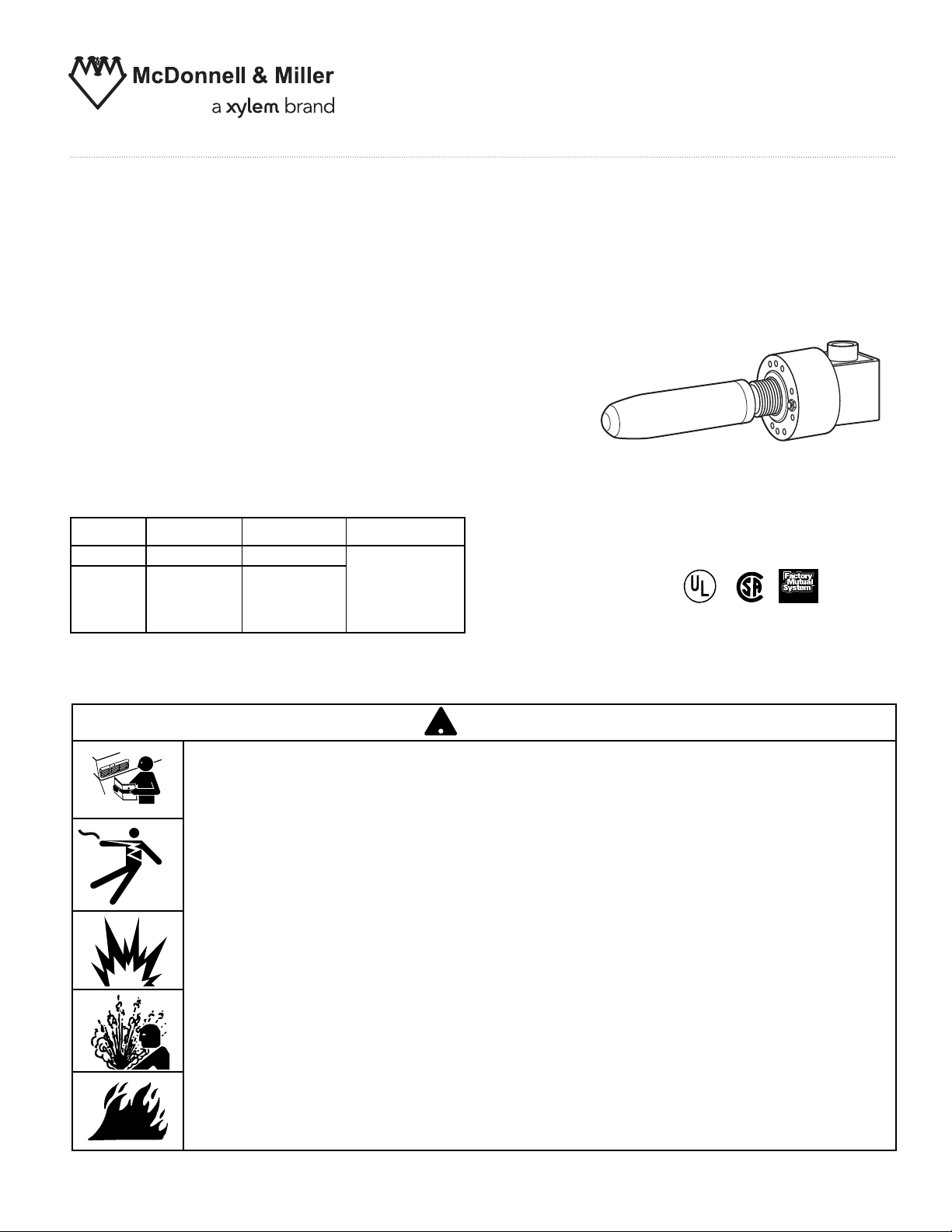
Series 6667 Replacement
!
Mechanism
Model 6667 on 120 VAC or 24 VAC Systems
Model 6667MV on Millivolt or 24 VAC Systems
Used on Series 61, 67, 69, 767, 70, and 70-B
Low Water Cut-offs
OPERATION
Maximum Steam Pressure: 20 psi
INSTRUCTION MANUAL
MM-209D
Electrical Ratings
Voltage Full Load Locked Rotor Pilot Duty
120 VAC 7.4 44.4 125 VA at
240 VAC 3.7 22.2 120 or 240 VAC
57.5 VA at
120 or 240 VDC
On D.C. Service be sure to connect (+) positive
wire to terminal marked (2).
CAUTION
WARNING
• Before using product, read and understand instructions.
• Save these instructions for future reference.
• All work must be performed by qualified personnel trained in the proper application,
installation, and maintenance of plumbing and electrical equipment and/or systems in
accordance with all applicable codes and ordinances.
WARNING
Series 6667
®
Approved
• To prevent electrical shock, turn off the electrical power before making electrical
connections.
• To prevent serious burns bleed off all pressure and let boiler cool down to 80˚F (27˚C).
• Drain water level down below the control before taking the control out of the boiler.
Failure to follow this warning could cause property damage, personal injury or death.
2
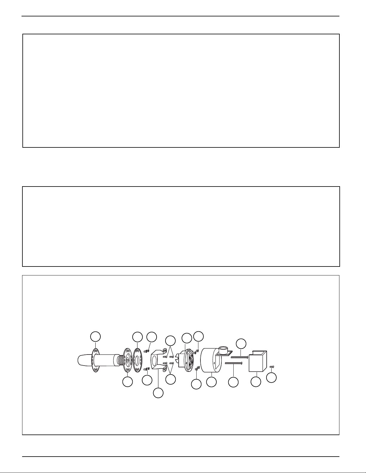
a. See figure 1. Turn off all electrical power to the boiler. (There may be more than one power
source to the boiler). Bleed off all pressure and let the boiler cool down to 80˚F (27˚C).
Drain water level in boiler down below the control. Remove screw (A) and cover (B). Tag all
wires for reconnection later. Disconnect wires from the terminals and remove conduit connection from housing (C). Remove two (2) screws (D) and switch housing (C).Remove four
(4) screws (E) and remove switch (F). Remove four (4) screws (G) and bracket (H).
Remove four (4) screws (J) and ring (K). The float and bellows assembly (L) can now be
removed. Clean the gasket surface and mount the new float and bellows assembly.
b. Disassemble the new 6667 by removing screw (A) and cover (B). Remove the two (2) nuts
on the back side of screws (D) and pull the assembly apart.
STEP 1 - Preparation
STEP 2 - Installation on 61, 67, 767, 70, and 70-B
For installing in a 69 Series see Step 3
a. See figure 1. Slip gasket (M) over float (L) and slide into body. Make sure that word TOP on
the bellow base is at the top. Align the holes in gasket (M) with holes in the body, float and
bellows assembly (L) and ring (K). Using four (4) screws (J) attach (L) and (K) to the body.
Attach bracket (H) using four (4) screws (G) to ring (K) and body. Install switch (F) into
bracket (H), making sure that the yoke on the switch fits around the roller in float and bellows assembly (L) and that the word TOP on the switch is at the top. Attach with four (4)
screws (E). Attach housing (C) using two (2) screws (D). Install conduit connector and
reconnect wires to their proper terminals. Install cover (B) using screw (A).
E
L
J
F
C
B
D
G
H
M
K J
G
E
D
A
Figure 1

3
a. Follow STEP 1-a.
STEP 3 - Installation on 69 Series
b. See figure 2. Remove eight (8) screws (N) and clamping ring (O). Mark position of float
shield (P) with respect to barrel casting (R). Inspect and clean float shield (P). Clean the
gasket surfaces, being careful not to scratch them. NOTE: On newer models the gasket
has been replaced with square cut rings (items (T) in figure 2). Place gasket (S) over float
shield (P) and insert the float shield (P) into barrel casting (R). Line up the marks that you
applied above. Using clamping ring (O) and eight (8) screws (N) secure the float shield (P)
to the barrel casting (R).
c. Follow STEP 2-a.
a. Run the control through several cycles of operation before leaving the job site.
STEP 4 - Testing
R
P
T
O
S
N
M
L
K
J
J
H
G
G
F
E
E
C
D
D
B
A
Figure 2

MAINTENANCE
TROUBLESHOOTING
SCHEDULE:
• Blow down weekly during heating season.
(On 61, 67, 767, 70 and 70B). Blow down
weekly if operating pressure is 15 psi or lower.
Blow down daily if operating pressure is 15 psi
or higher.
• Follow ASME Boiler and Pressure Vessel
Code - Section VI Paragraph 7.07G. It states
that the controls should be dismantled annually
by qualified personnel, to the extent necessary
to insure freedom from obstructions and proper
functioning of the working parts.
• Check for leaks at the gasket surfaces and
solder joints. Repair or replace components as
needed.
• Check all wiring for brittle or worn insulation.
• Replace control every 10 years.
Problem:
1. Control does not turn burner off on low water.
a. Cause: Build up of scale and sediment.
Test: Dismantle control and check for any
build up or any other obstructions that
would prevent the control from turning
off the burner. Don’t forget to check the
corrugations of the bellows.
Solution: Clean or replace as necessary.
b. Cause: Terminals 1 and 2 on the No. 11 switch
are not opening up on low water.
Test: With a continuity meter or ohm meter
check if terminals 1 and 2 open on low
water. If they do not open, take the switch
off the control and work it manually.
Solution: If terminals 1 and 2 do not open when
operated manually, replace the switch. If
they do open see item a. above.
Problem:
2. Control does not turn electric feeder off.
a. Cause: Build up of scale between the corruga-
tions of the bellows. On 69 units the float
shield could be tipped down.
Test: Dismantle the control and check for
scale build up between the bellow corrugations. On the 69 series control check
the float shield to make sure it is in the
proper position.
Solution: Clean or replace as necessary. On 69
series reposition the float shield.
Xylem Inc.
8200 N. Austin Avenue
Morton Grove, Illinois 60053
Phone: (847) 966-3700
Fax: (847) 965-8379
www.xyleminc.com/brands/mcdonnellmiller
McDonnell & Miller is a trademark of Xylem Inc. or one of its subsidiaries.
© 2012 Xylem Inc. MM-209D April 2012 Part No. 246776
 Loading...