

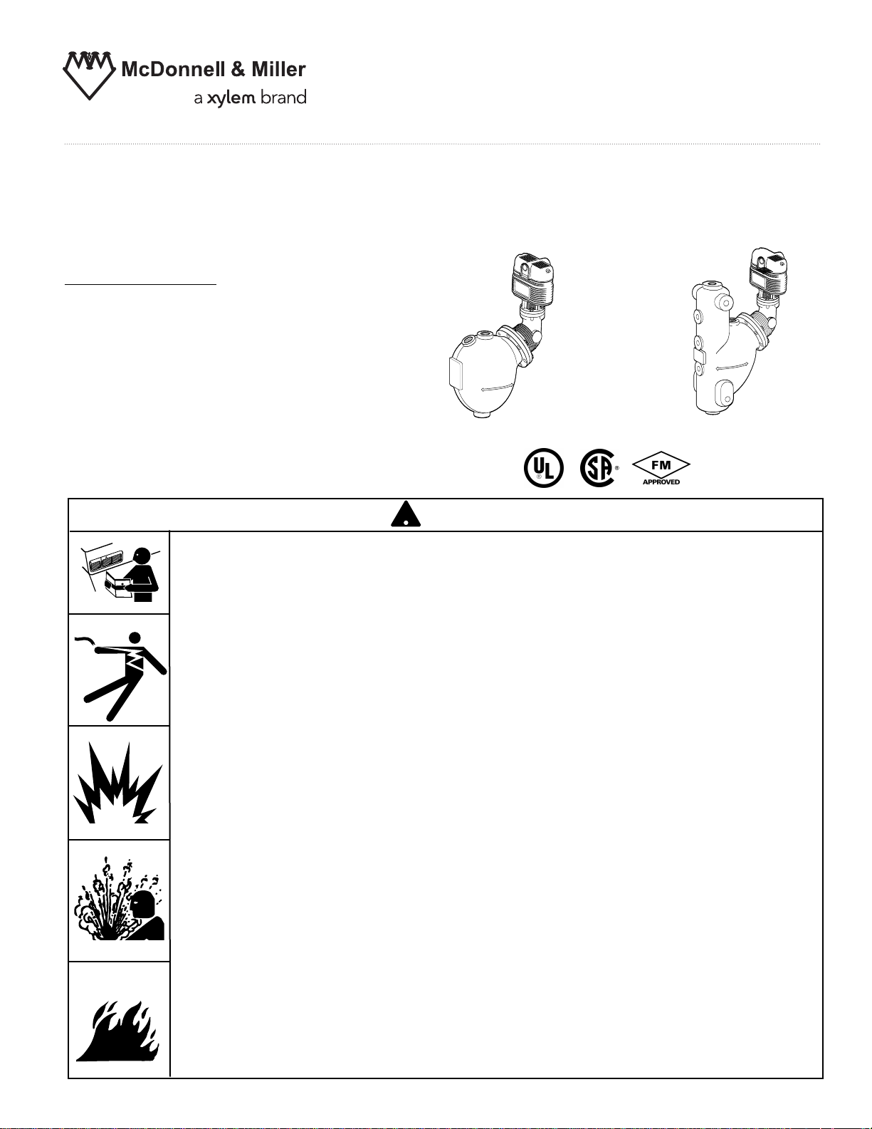
Series 93/193 and Series 94/194
WARNING
CAUTION
!
Low Water Cut-Off/Pump Controllers
For Steam Boilers and Level Control Applications
Typical Applications:
– Primary or secondary pump controller/
low water fuel cut-off
for steam boilers
– Motorized valve controller
– Proportional valve controller
– Low water cut-off
– High water cut-off
– Alarm actuation
Series 93 or Series 94
INSTRUCTION MANUAL
MM-404J
Series 193 or Series 194
WARNING
• Before using this product read and understand instructions.
• Save these instructions for future reference.
• All work must be performed by qualified personnel trained in the proper application, installation, and maintenance of plumbing, steam, and electrical equipment and/or systems in
accordance with all applicable codes and ordinances.
• To prevent serious burns, the boiler must be cooled to 80˚F (27˚C) and the pressure must be
0 psi (0 bar) before servicing.
• To prevent electrical shock, turn off the electrical power before making electrical connections.
• This low water cut-off must be installed in series with all other limit and operating controls
installed on the boiler. After installation, check for proper operation of all of the limit and
operating controls, before leaving the site.
We recommend that secondary (redundant) Low Water Cut-Off controls be installed on all
•
steam boilers with heat input greater than 400,000 BTU/hour or operating above 15 psi of
steam pressure. At least two controls should be connected in series with the burner
control circuit to provide safety redundancy protection should the boiler experience a
low-water condition. Moreover, at each annual outage, the low water cutoffs should be
dismantled, inspected, cleaned, and checked for proper calibration and performance.
• To prevent serious personal injury from steam blow down, connect a drain pipe to the control
opening to avoid exposure to steam discharge.
• To prevent a fire, do not exceed the switch contact rating.
California Proposition 65 warning! This product contains chemicals known to the
•
state of California to cause cancer and birth defects or other reproductive harm.
Previous controls should never be installed on a new system. Always install new
•
controls on a new boiler or system.
Failure to follow this warning could cause property damage, personal inj ury or death.
CAUTION:
•
A more frequent replacement interval may be necessary based on the condition of
the unit at time of inspection. McDonnell Miller s warranty is one (1) year from date
of installation or two (2) years from the date of manufacture.
!
&
'
OPERATION
PUMP
OFF
BURNER
OFF
BURNER
“CUT-OFF LEVEL”
AT CAST LINE
2
3
/16"
(56mm)
PUMP OFF
PUMP ON
(27mm)
1
1
/16"
BURNER
“CUT-OFF LEVEL”
AT CAST LINE
BURNER OFF
(35mm)
BURNER ON
1
3
/8"
BURNER
“CUT-OFF LEVEL”
AT CAST LINE
BURNER OFF
(35mm)
BURNER ON
1
3
/8"
MOTORIZED
VALVE
CLOSED
BURNER
OFF
BURNER
“CUT-OFF LEVEL”
AT CAST LINE
2
3
/16"
(56mm)
MOTORIZED
VALVE
CLOSED
MOTORIZED
VALVE
OPEN
(27mm)
1
1
/16"
W
A
R
N
I
N
G
C
A
U
T
ION
!
®
Electrical Ratings
Models with 5 or 5-M Switch
Maximum Pressure:
Series 93/193: 150 psi (10.5 kg/cm
Series 94/194: 250 psi (17.6kg/cm
Models with 7B or 7B-M Switch
2
)
2
)
Pump and Burner Switch Contact Ratings
Voltage Pilot Duty Only
120 VA
C
345 VA
240 VAC
Switch Settings
1
/8
Values are ±
Models with 5 or 5-M Switches
Setting In. (mm) In. (mm)
Pump Off 23/
Pump On 11/8(29)
Burner On 13/8(35) 13/8(35)
Burner Off 0
” (3mm)
Approximate
Distance Above
Cast Line Differential
(56) 11/16(27)
16
Switch Ratings
Burner Valve
120 VAC
VA 0 - 135 ohms @ 24 VAC
345
240 VAC
Models with 7B or 7B-M Switches
Approximate
Distance Above
Cast Line Differential
Setting In. (mm) In. (mm)
Valve Full 23/
16
(56) 11/16(27)
Closed
Valve Full 11/8(29)
Open
Burner On 13/8(35) 13/8(35)
Burner Off 0
2
NOTE: Due to the slower operation of some
motorized valves, complete valve opening or
closing may occur at slightly different
levels than indicated above.
INSTALLATION –
11/2"
STEAM EQUALIZING PIPE
V
ERTICAL EQUALIZING PIPE
BLOW DOWN VALVE
NORMAL BOILER WATER LINE
AS A PRIMARY
LOW WATER CUT-OFF/PUMP
CONTROLLER
BURNER “CUT-OFF LEVEL”
A
T CAST LINE
LOWEST
PERMISSIBLE
W
ATER LEVEL
WATER
EQUALIZING
PIPE
STEAM EQUALIZING PIPE
VERTICAL EQUALIZING PIPE
BLOW DOWN VALVE
AS A SECONDARY
LOW WATER CUT-OFF/PUMP
CONTROLLER
BURNER “CUT-OFF LEVEL”
AT CAST LINE
LOWEST
PERMISSIBLE
WATER LEVEL
BURNER OFF
WATER
EQUALIZING
PIPE
TOOLS NEEDED:
o (2) pipe wrenches, one (1) flathead screw
Tw
driver, and pipe thread dope.
IMPORTANT: Follow the boiler manufacturer's
uctions along with all applicable codes and
instr
ordinances for piping, blow-down valve, water
gauge glass, tri-cock and electrical requirements.
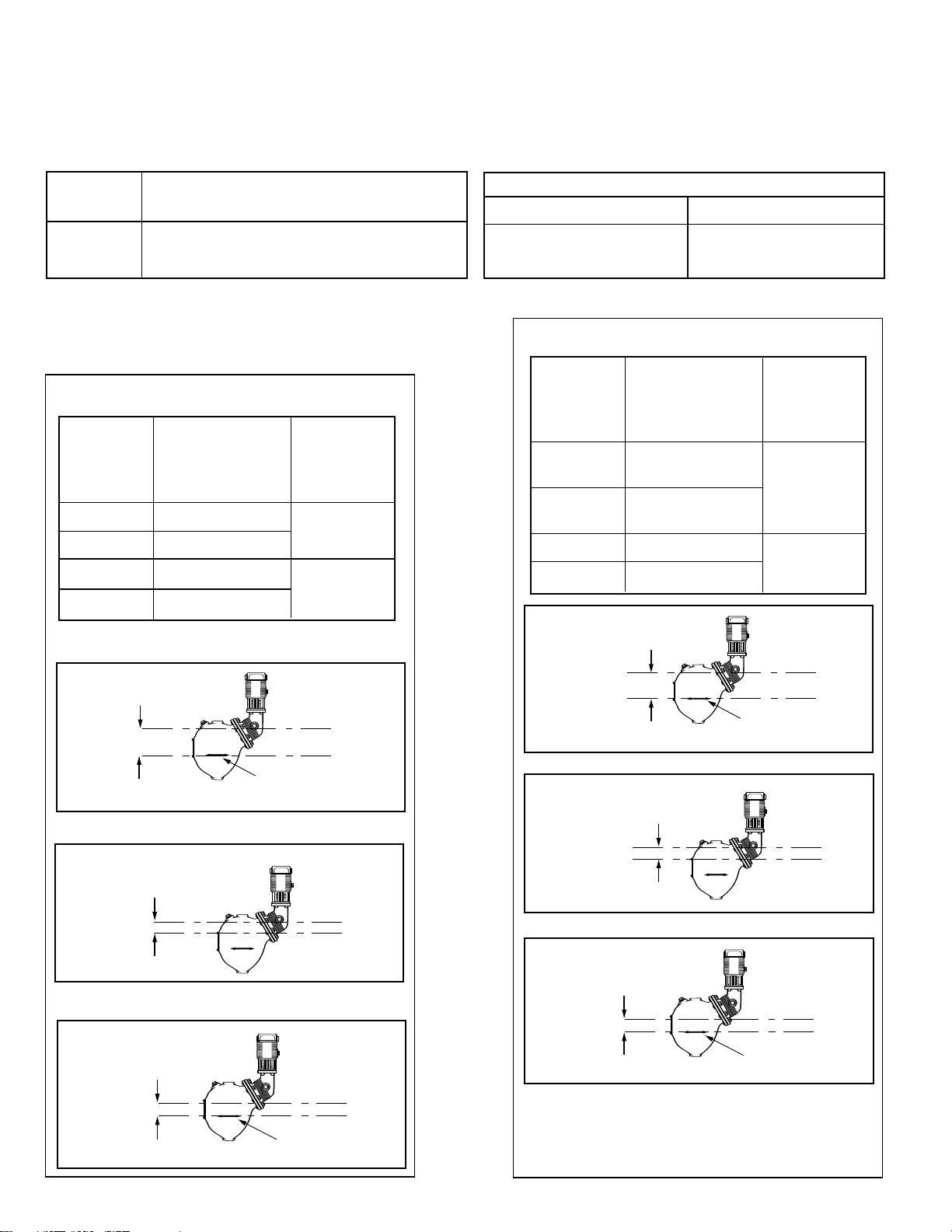
STEP 1 - Determine the Position of the Low Water Cut-Off/Pump Controller
If the control will be the primary low
water fuel cut-off, size the steam (top) and
ater (bottom) equalizing pipe lengths so
w
that the horizontal cast line on the body is
1 1/2” (38mm) belo
water level, but not lower than the lowest
e permissible water level, as deter-
saf
mined by the boiler manufacturer.
If the control will be the secondary low
water fuel cut-off, size the steam (top) and
ater (bottom) equalizing pipe lengths so
w
that the horizontal cast line on the body is
at or above the lowest safe permissible
water le
vel, as determined by the boiler
manufacturer.
w the boiler’s normal
OR
3
A
B
C
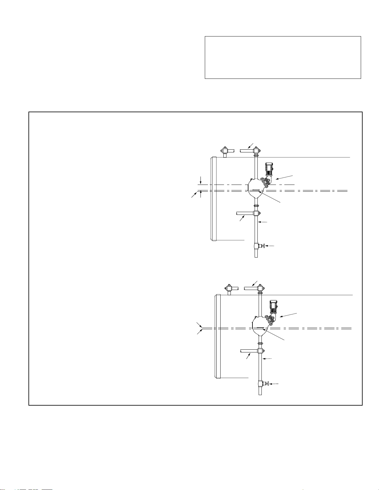
STEP 2 - Installing the Low Water Cut-Off/Pump Controller
A
E
C
D
A
C
G
11/2"
STEAM EQUALIZING PIPE
V
ERTICAL EQUALIZING PIPE
BLOW DOWN VALVE
NORMAL BOILER WATER LINE
AS A PRIMARY
LOW WATER CUT-OFF/PUMP
CONTROLLER
BURNER “CUT-OFF LEVEL”
A
T CAST LINE
LOWEST
PERMISSIBLE
W
ATER LEVEL
WATER
EQUALIZING
PIPE
STEAM EQUALIZING PIPE
VERTICAL EQUALIZING PIPE
BLOW DOWN VALVE
AS A SECONDARY
LOW WATER CUT-OFF/PUMP
CONTROLLER
BURNER “CUT-OFF LEVEL”
AT CAST LINE
LOWEST
PERMISSIBLE
WATER LEVEL
BURNER OFF
WATER
EQUALIZING
PIPE
For Series 93/193 or 94/194 (except 94-A, 193-D and 193-G Models)
a. Mount and pipe the control (A) on vertical equalizing
pipes (B) at the required ele
vation as determined in
Step 1.
Install a full-ported blow-down valve (C) directly
w the lower cross.
belo
NOTE:
1” (25mm) NPT tappings are provided on Series
93/193 controls.
1 1/4” (32mm) NPT tappings are provided for Series
94/194 controls and 193-B Model.
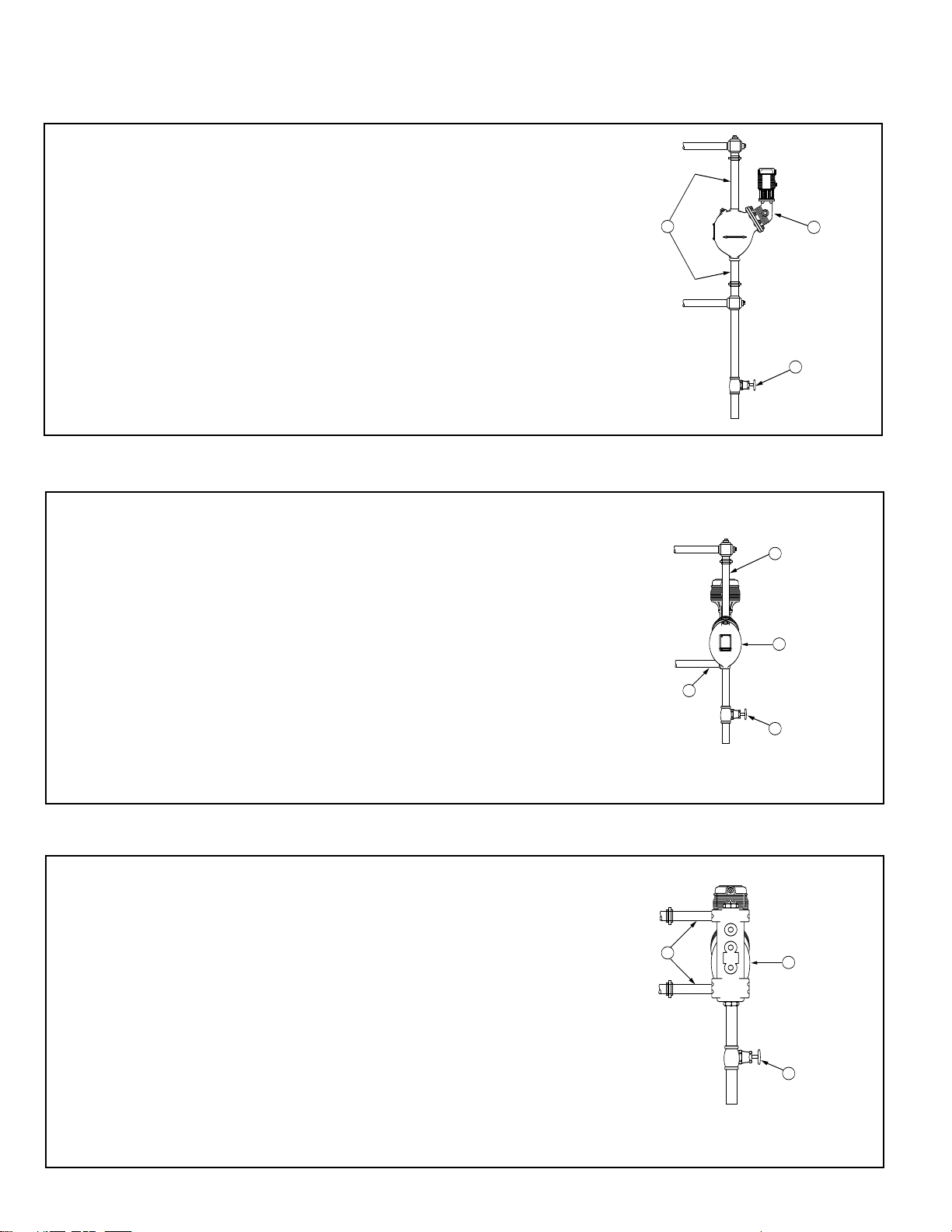
For 94-A and 193-G Models
a. Mount and pipe the control (A) with a vertical upper
(D) and horizontal lower (E) equalizing piping at the
required ele
Install a full-ported blow-down valve (C) on the low
body connection.
vation as determined in Step 1.
er
NOTE:
1 1/4” (32mm) NPT tappings are provided for 94-A
Model control.
1” (25mm) NPT tappings are provided for 193-G
Model control.
For 193-D Models
a. Mount and pipe the control (A) with a horizontal
upper and lower (G) equalizing piping at the
vation as determined in Step 1.
required ele
Install a full-ported blow-down valve (C) on the lo
body connection.
NOTE:
1” (25mm) NPT tappings are provided for 193-D
Model control.
wer
4

STEP 3 - Removing Float Blocking Plugs and Dowels
I
H
I
H
!
CAUTION
The plug and rod must be reinstalled before control is shipped installed on the
boiler, and removed after boiler is placed and installed.
Failure to follow this caution may damage the float and operating mechanism.
a. Using a pipe wrench, remove the float blocking plugs (I)
and dowels (H) from the control as sho
b. Using a pipe wrench, screw the pipe plugs provided with
control into the open tappings
.
wn below.
Series 193 / 194
Series 93 / 94
5

STEP 4 - Installing a Water Gauge Glass and Tri-Cocks
C
UT-OFF LEVEL
CUT-OFF
LEVEL
3"
3"
B
D
F
E
C
K
L
JH
GAUGE GLASS
(TYPICAL)
TRI-COCK
(TYPICAL)
I
H
I
H
!
NOTE: A separate water column for installation of
gauge glass and tri-cocks may be required for boilers
a. Determine pipe size of tri-cock and
sight glass tappings for the control
being installed including center
distance of sight glass tappings.
NOTE:
These items are not provided with
control and must be purchased
separately
with a Series 93 or Series 94 control. Follow the
manufacturer’s instructions to install the water column.
Tri-Cock Gauge Glass Tapping Gauge Glass Tapping
Tapping Pipe Size Center Distance
Unit B C D E F H J K L
193
193-A
193-B
193-D
193-G
194
194-A
194-B
1
⁄2 (15)
1
⁄2 (15)
3
⁄4 (20)
1
⁄2 (15)
1
⁄2 (15)
1
⁄2 (15)
1
⁄2 (15)
3
⁄4 (20)
1
⁄2 (15)
1
⁄2 (15)
3
⁄4 (20)
1
⁄2 (15)
1
⁄2 (15)
3
⁄4 (20)
1
⁄2 (15)
1
⁄2 (15)
3
⁄4 (20)
1
⁄2 (15)
1
⁄2 (15)
1
⁄2 (15)
1
⁄2 (15)
3
⁄4 (20)
1
⁄2 (15)
1
⁄2 (15)
1
⁄2 (15) 111⁄2 (292)
1
⁄2 (15) 111⁄2 (292)
1
⁄2 (15) 111⁄2 (292)
1
⁄2 (15) 115⁄8 (295)
1
⁄2 (15)
3
⁄4 (20)
1
⁄2 (15)
3
⁄4 (20)
1
⁄2 (15) 123⁄4 (324)
3
⁄4 (20) 123⁄4 (324)
1
⁄2 (15) 127⁄8 (327)
3
⁄4 (20) 127⁄8 (327)
b. Install tri-cocks and gauge glass following
manufacturer’s instructions.
6
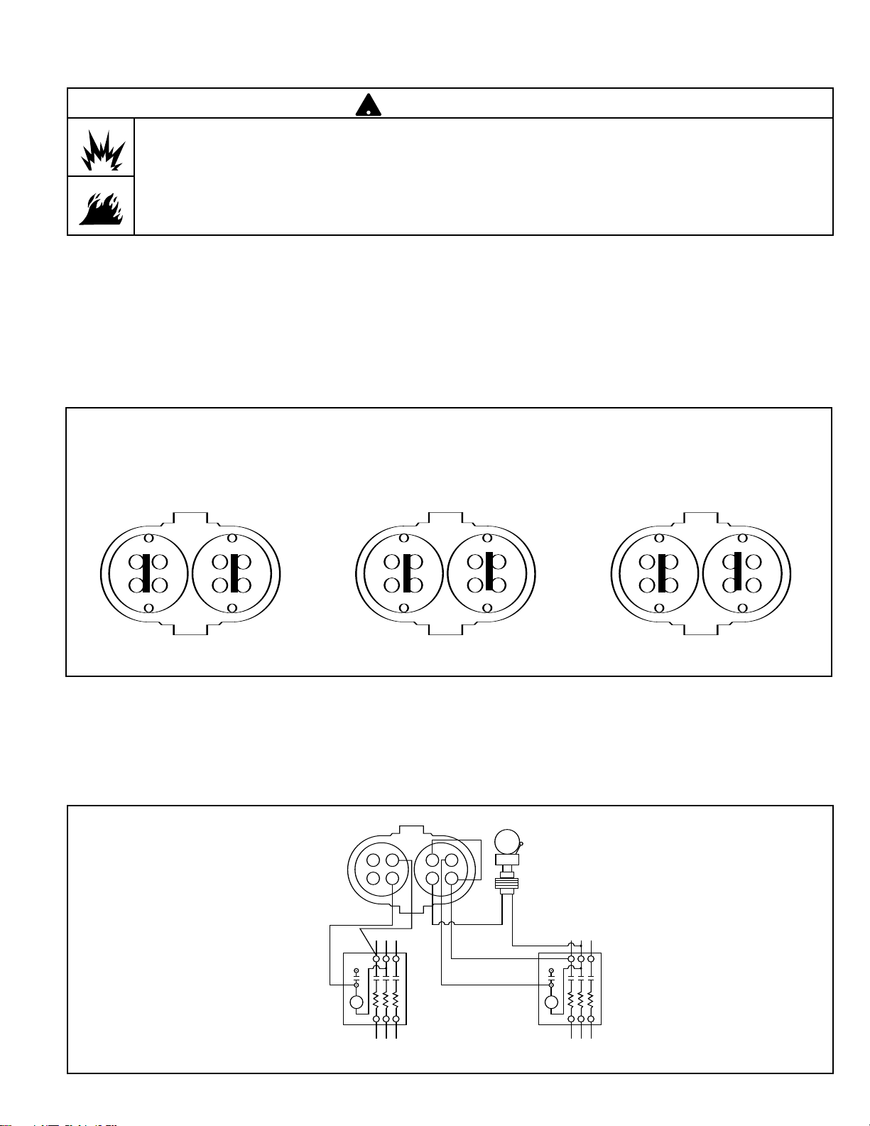
STEP 5 - Electrical Wiring
!
2 4
1 3
BLUE
BOILER FEED PUMP OFF–
BURNER ON–ALARM OFF
BOILER FEED PUMP ON–
BURNER ON–ALARM OFF
BOILER FEED PUMP ON–
BURNER OFF–ALARM ON
RED
3 1
4 2
2 4
1 3
BLUE RED
3 1
4 2
2 4
1 3
B
LUE RED
3 1
4 2
BLUE
NO. 5
SWITCH
TO BURNERTO PUMP
LINE
123
4
4
3
RED
LINE
ALARM
TRANS.
• To prevent electrical shock, turn off the electrical power before making electrical connections.
• This low water cut-off must be installed in series with all other limit and operating controls installed on the
boiler. After installation, check for proper operation of all of the limit and operating controls, before leaving
the site.
Failure to follow this warning could cause electrical shock, an explosion and/or a fire, which could result in
property damage, personal injury or death.
Wiring Diagrams
WARNING
NOTE: The following diagrams are provided for reference only.
If available, manufacturer’s wiring diagrams
should always be followed to connect the device
being operated.
Switch Operation
For Series 93/193 or 94/194 with 5 or 5-M Switch
Red switch terminals 1 and 2 are for burner circuit contacts, terminals 3 and 4 are for the low level alarm
circuit contacts.
Blue switch terminals 3 and 4 are for feeder/pump control contacts, terminals 1 and 2 are for high level
alarm circuit contacts.
Pump Control, Low Water Cut-Off and Alarm
7
L
OW WATER CUT-OFF CIRCUIT
B
LUE
N
O. 5
S
WITCH
B
URNER
STARTER
1
2
R
ED
LINE
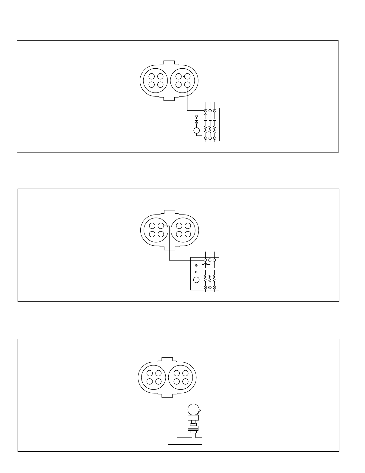
Low Water Cut-Off Only
PUMP CONTROL CIRCUIT
BLUE
NO. 5
SWITCH
PUMP
STARTER
4
3
RED
LINE
ALARM CIRCUIT
BLUE
NO. 5
SWITCH
ALARM
TRANS.
NEUTRAL
3
4
RED
LINE
!
2 4
1 3
BLUE
BOILER FEED PUMP OFF–
BURNER ON–ALARM OFF
BOILER FEED PUMP ON–
BURNER ON–ALARM OFF
BOILER FEED PUMP ON–
BURNER OFF–ALARM ON
RED
3 1
4 2
2 4
1 3
BLUE RED
3 1
4 2
2 4
1 3
B
LUE RED
3 1
4 2
BLUE
NO. 5
SWITCH
TO BURNERTO PUMP
LINE
123
4
4
3
RED
LINE
ALARM
TRANS.
Pump Control Only
Low Water Alarm Only
8

TO BURNER
LINE
13
4
432
1
COMMON
CLOSING CIRCUIT
OPENING CIRCUIT
NO. 7B
SWITCH
BLUE
RED
2 4
1 3
BLUE
BURNER ON–ALARM OFF
VALVE CLOSED
BURNER ON–ALARM OFF
VALVE OPEN
BURNER OFF–ALARM ON
VALVE OPEN
RED
3 1
4
2 4
1 3
BLUE
RED
3 1
4
2 4
1 3
BLUE
RED
3 1
4
For Series 93/193 or 94/194 with 7B or 7B-M
Red terminals 1 and 2 are the burner circuit contacts, terminals 3 and 4 are the low level alarm circuit
contacts.
Blue terminal 3 is the common contact, terminals 1 and 4 are the output contacts.
NOTE: The 7B switch is a 135 ohm potentiometer slide
wire control for use with an electric valve operator with
the same rating.
Proportional Control, Low Water Cut-Off and Alarm
9
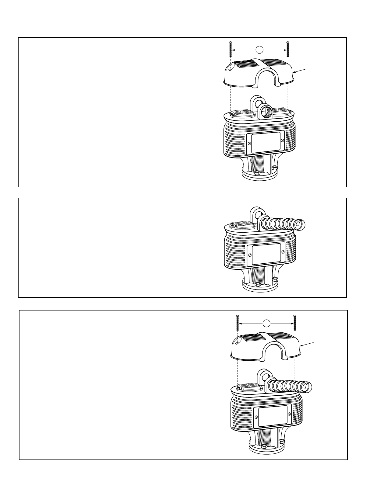
A
SWITCH
COVER
A
SWITCH
COVER
Wiring Connections
TO BURNER
LINE
13
4
432
1
COMMON
CLOSING CIRCUIT
OPENING CIRCUIT
NO. 7B
SWITCH
BLUE
RED
2 4
1 3
BLUE
BURNER ON–ALARM OFF
VALVE CLOSED
BURNER ON–ALARM OFF
VALVE OPEN
BURNER OFF–ALARM ON
VALVE OPEN
RED
3 1
4
2 4
1 3
BLUE
RED
3 1
4
2 4
1 3
BLUE
RED
3 1
4
a. Remove two screws (A) and lift off switch
cover.
b. Connect BX armored cable or Thinwall electrical
metal tubing to the integral fitting hub. Connect
wires to terminals following appropriate wiring
diagram from pages 8 and 9 for your application.
NOTE: Follow local codes and standards when
selecting the types of electrical fittings and conduit
to connect to control.
c. Replace switch cover and fasten with two
screws (A).
10
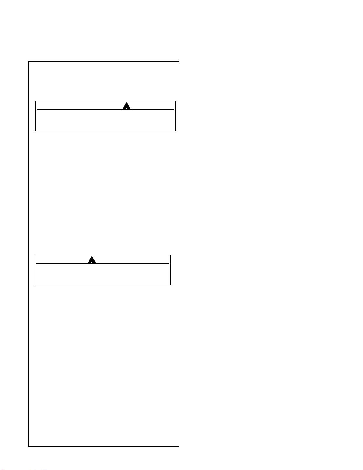
STEP 6 - Testing
!
!
TROUBLESHOOTING
– Dimensions shown are typical.
– The following testing procedure is only meant to serve
as a verification of proper operating sequence.
a. Turn on power to boiler and pump circuits.
With the boiler empty, the pump should turn on (5
or 5-M switch models) or the valve open (7B or
7B-M switch models). The burner should remain off
and boiler should begin to fill with water.
CAUTION
Immediately turn off all power if the burner turns on
with no water in the gauge glass. Investigate further
before continuing procedure.
b. For Automatic Reset Models
When water level in the gauge glass is approximately
1 3/8” (35mm) above the horizontal cast line, the
burner should turn on.
For Manual Reset Models
When water level in the gauge glass is approximately
1 3/8” (35mm) above the horizontal cast line, press
the manual reset button and the burner should turn on.
c. For 5 or 5-M Switch Models
When water level in the gauge glass is approximately
2 3/16” (56mm) above the horizontal cast line, the
pump should turn off.
For 7B or 7B-M Switch Models
When water level in the gauge glass is approximately
2 3/16” (56mm) above the horizontal cast line, the
valve should be closed.
CAUTION
If pump does not turn off or valve close, turn off
water supply to boiler. Investigate further before
continuing procedure.
d. With the water in the boiler at its normal level and
burner on, SLOWLY open the blow-down valve
until it is fully open. As the water level in the gauge
glass begins to drop, verify that the following occurs.
For 5 or 5-M Switch Models
When water level drops to approximately 1 1/8”
(29mm) above the horizontal cast line, the pump
should turn on. When water level drops to the hori
zontal cast line, the burner should turn off.
For 7B or 7B-M Switch Models
As the water level drops, the valve should begin to
open. When the water level drops to approximately
1 1/8” (29mm) above the horizontal cast line, the
valve should be full open.
When the water level drops to the horizontal cast
line, the burner should turn off.
e. Close the blow-down valve after burner turns off
and restore water level to normal operating level.
f. Repeat testing procedure several times to ensure
proper operation of control.
g. After testing and verification of control operation,
the boiler can be returned to service.
Erratic operation of the control is the most common symptom
that occurs. Erratic operation can be defined as pump and/or
burner switches not switching at proper levels. Refer to the
following list of items to check if the control is not operating
properly.
1. Float Ball is Crushed
Crushed floats are typically caused by improper blowdown. Drain piping from blow-down valve to drain should
be checked for proper pitch and the blow-down procedure
followed when blowing down the control. Purchase and
install a new float ball after investigating and correcting
the problem.
2. Float Ball is Filled with Water
The seam weld on the float can sometimes deteriorate.
This can be caused by the type of chemical treatment
used in the boiler. While this is a rare occurrence, the
chemical treatment supplier should be consulted to determine if a reaction could occur. Purchase and install a new
float ball after investigating and correcting the problem.
3. Float Arm Springs are Bent
The pivot springs located on either side of the float rod
should be flat and straight. If they become bent, the usual
cause is mishandling of the unit during installation or
improper blow-down.The control should never be picked
up by the float ball or allowed to hang from the bowl by the
float. Drain piping from blow-down valve to drain should be
checked for proper pitch and the blow-down procedure
followed when blowing down control. Purchase and install
new control or head mechanism after investigating and
correcting the problem.
4. Switch Contact Springs Broken
The contact springs can break if the electrical rating is
exceeded. Purchase and install new switch assembly or
head mechanism after investigating and correcting the
problem.
5. Switch Contact Springs Misaligned
Misalignment of the contact arms is usually associated
with damage to the control during shipment or installation.
Purchase and install new switch assembly or head
mechanism after investigating and correcting the problem.
6. Internal (Wetted) Parts Dirty
The internal parts can operate improperly if dirt, scale or
rust is allowed to build. This condition can be a result of
not blowing down the control as recommended and/or
improper boiler water chemical treatment. Purchase and
install new control or head mechanism after investigating
and correcting the problem.
11
MAINTENANCE
!
Valve #2
Valve #1
!
!
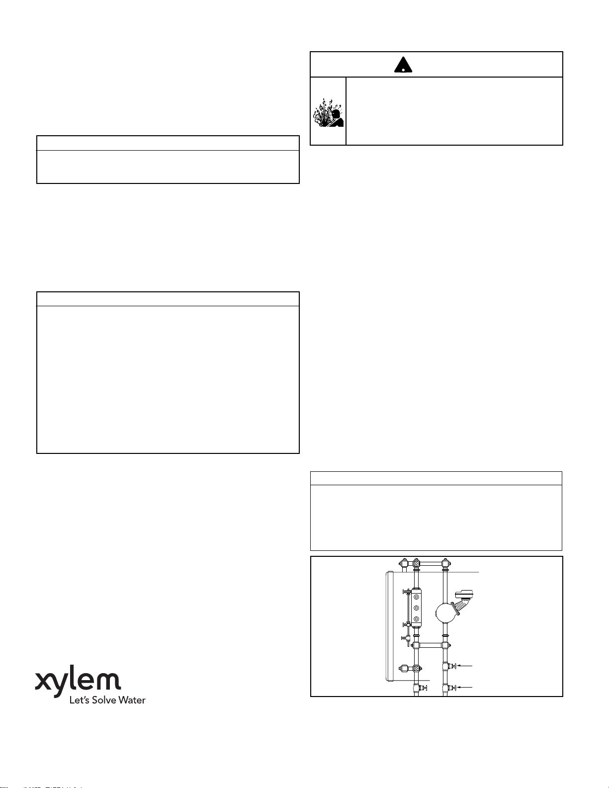
BLOW DOWN PROCEDURE:
SCHEDULE:
Blow down control as follows when boiler is
in operation.
• Daily if operating pressure is above 15 psi.
• Weekly if operating pressure is below 15 psi.
NOTE
More frequent blow-down may be necessary
due to dirty boiler water and/or local codes.
• Remove head assembly and inspect water
side components annually. Replace head
assembly if any of the internal components are
worn, corroded or damaged or if control no longer
operates properly.
• Inspect the float chamber and equalizing piping
annually. Remove all sediment and debris.
NOTE
The control may need to be inspected and
cleaned more frequently on systems where there
is the potential of excessive scale or sludge
build-up. This includes systems:
• With high raw water make-up
• With no condensate return
• With untreated boiler water
• Where significant changes have been
made to the boiler-water chemical
treatment process
• With oil in the boiler water
CAUTION
To prevent serious personal injury from steam
pipe blow down, connect a drain pipe to the
control opening to avoid exposure to steam
discharge.
Failure to follow this caution could cause
personal injury.
When blowing down a control at pressure, the blow
down valves should be opened slowly. The piping
needs to be warmed up and stagnant water in the
drain piping needs to be pushed out. Suddenly
opening a blow down valve causes steam to
condense, which creates water hammer. Damage to
components can occur when water hammer occurs
due to improper blow down piping.
For these reasons, McDonnell & Miller recommends
a dual valve blow-down system for each control.
Blow down the control when the water in the boiler
is at its normal level and the burner is on.
NOTE: Refer to page 2 for switch operating points.
• Open upper valve (#1)
• Slowly open the lower valve (#2)
• Water in the sight glass should lower.
• As the water in the sight glass lowers, the
pump should turn on.
• As the water continues to lower in the sight
glass, the burner should turn off.
• Slowly close the lower valve (#2).
• Close the upper valve (#1)
• The water level in the sight glass should rise, first
turning on the burner and then turning off the pump.
NOTE: On manual reset models, the reset button
will need to be pressed after the water level has
been restored before the burner will operate.
Replace head mechanism every 5 years.
More frequent replacement may be required when
severe conditions exist.
Replacement parts are available from your local
authorized McDonnell & Miller Distributor.
The use of parts or components other than those
manufactured by McDonnell & Miller will void all
warranties and may affect the units compliance with
listings or regulating agencies.
Xylem Inc.
8200 N. Austin Avenue
Morton Grove, Illinois 60053
Phone: (847) 966-3700
Fax: (847) 965-8379
www.xyleminc.com/brands/mcdonnellmiller
McDonnell & Miller is a trademark of Xylem Inc. or one of its subsidiaries.
© 2013 Xylem Inc. MM-404J July 2013 Part No. 246043
NOTE
If this sequence of operation does not occur as
described, immediately close all the valves, turn off the
boiler and correct the problem. Inspection/cleaning of
the float mechanism may be required to determine why
the control was not working properly. Retest the control
after the problem has been identified and corrected.
 Loading...