

Series FS4-3
General Purpose
Liquid Flow Switch
INSTRUCTION MANUAL
MM-601H
®

SPECIFICA
Maxim
um Liquid Pressure: 160 psi (11.3 kg/cm
TIONS
Liquid Temperature
Range (T
- 300˚F (0 - 149˚C)
L
): 32
2
)
Ambient Temperature Range (T
): 32
S
- 120˚F (0 - 49˚C)
Electrical Enclosure Rating: Nema Type 1 (IP 21)
Maximum Velocity: 10ft/sec (3M/sec)
Pipe Connection Thread Size: - 1" NPT - All models
except “J”
- 1" BSPT - “J” models
ELECTRICAL
Switch Rating (Amperes)
Motor
Voltage Full Load Locked Rotor Pilot Duty
120 VAC 7.4 44.4
240 VAC 3.7 22.2
RATINGS
125 VA at
120 or 240 VAC
50 or 60 cycles
2
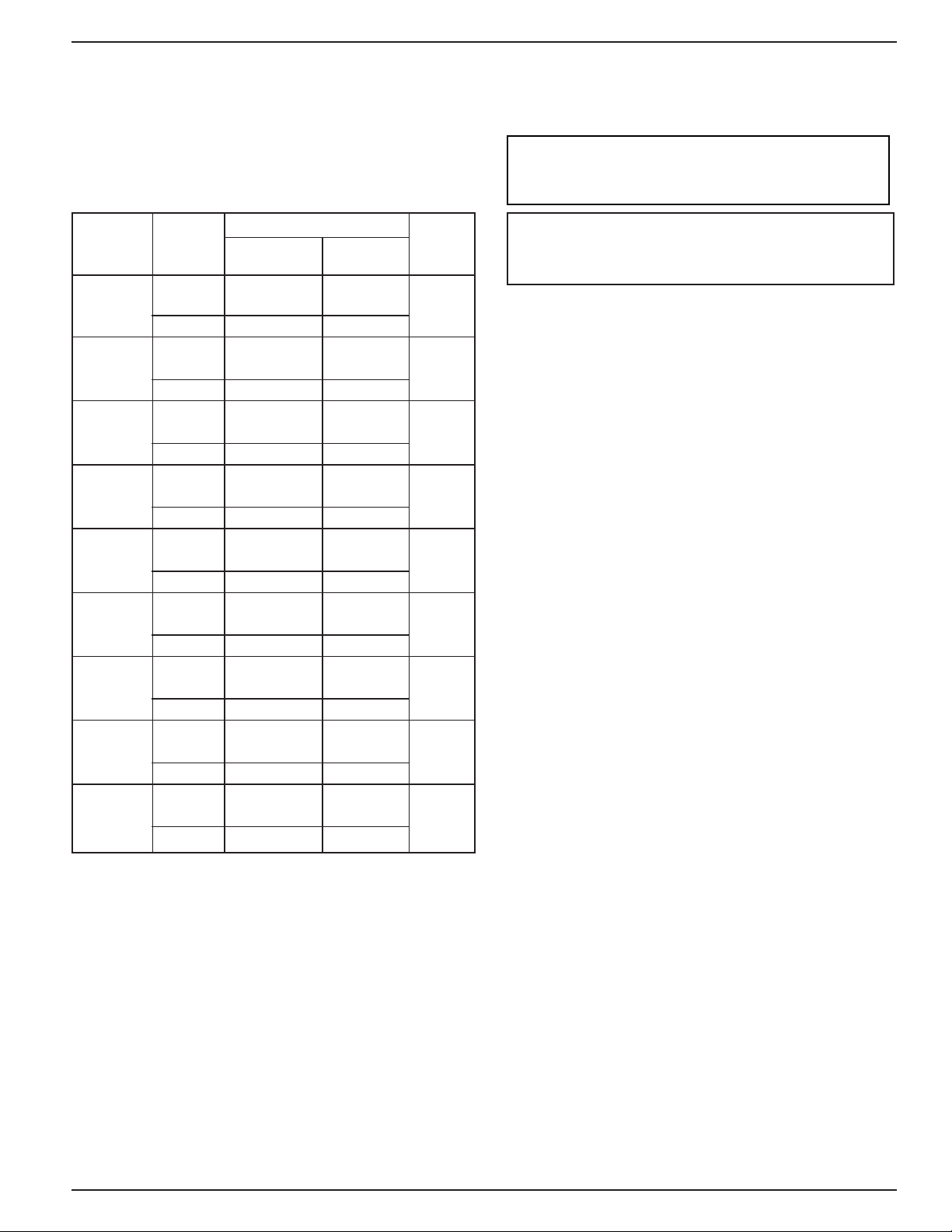
FLOW RATES
Flow rates required to activate the flow switch
are shown in chart below.These values were
calculated using clean water in a horizontal pipe.
Settings will vary when used to sense flow of other
fluids or if located in a vertical pipe.
NOTE: THIS PRODUCT IS NOT INTENDED
FOR USE IN POTABLE WATER
APPLICATIONS.
Pipe Mode of Operation
Size NPT Flow No Flow
in. (mm) Settings gpm (lpm) gpm (lpm)
Factory or
1 (25)
1
1
(32)
⁄
4
1
1
⁄
(40) Minimum 12.7 (48.1) 7 (26.5) 63
2
2 (50) Minimum 18.8 (71.2) 9.4 (35.6) 105
1
⁄
2
2
(65) Minimum 24.3 (92) 11.6 (43.9) 149
3 (80) Minimum 30 (113.6) 12 (45.4) 230
4 (100) Minimum 39.7 (150.3) 19.8 (74.9) 397
5 (125) Minimum 58.7 (222.2) 29.3 (110.9) 654
6 (150) Minimum 79.2 (300) 39.6 (150) 900
Minimum
Maximum 10.2 (38.6) 9.2 (34.8) (102)
Factory or
Minimum
Maximum 16.8 (63.6) 15 (56.8) (178)
Factory or
Maximum 23 (87.1) 19.5 (73.8) (239)
Factory or
Maximum 32.8 (124.1) 24 (90.8) (398)
Factory or
Maximum 42.4 (160.5) 37.5 (141.9) (565)
Factory or
Maximum 52.1 (197.2) 46.1 (174.5) (872)
Factory or
Maximum 73.5 (278.2) 64.2 (242) (1505)
Factory or
Maximum 115 (435.3) 92 (348.2) (2479)
Factory or
Maximum 166 (628.3) 123 (465.6) (3411)
6 (22.7) 3.6 (13.6) 27
9.8 (37.1) 5.6 (21.2) 47
Max. Flow
Rate gpm
(lpm) w/o
Paddle Damage
NOTE: DO NOT USE LIQUID FLOW SWITCHES
ON SYSTEMS WITH FLOW VELOCITY
GREATER THAN 10 FEET PER SECOND
(3 METERS PER SECOND).
Values are ± 10%
3

INSTALLATION –
STEP 1 - Paddle Sizing
Determine the correct paddle length for your installation from
the chart below.
Pipe SizePaddle Trim to Length
(Standard Length)
in. (mm) in. (mm) in. (mm)
1 (25) 1 (25) N/A
11/
4
11/2 (40) 2 (51) 11/2 (38)
2 (50) 2 (51) 15/
2
21/
3 (80) 3 (76) 25/
4 (100) 6 (152) 35/
6 (150) 6 (152) 55/8 (143)
8+ (200+) 6 (152) N/A
NOTE:
• All models (except FS4-3RP) include 4 paddles.
• FS4-3RP includes 1" and 6" paddles only.
(32) 2 (51) 11/
(65) 3 (76) 21/
1" (25mm)
4
8
4
8
8
(32)
3" (76mm)
(41)
(57)
(67)
(92)
6" (152mm)
2" (51mm)
a. If the paddle must be trimmed, measure the paddle
from the center of the large hole (A) to the length
required. Using non-serrated tin snips, trim the end (B)
on a curve just like the paddle was originally cut.
b. If the flow rate in the pipe exceeds the
Series FS4-3 “K”Factor
maximum adjustment on the Flow Switch
use the following formula to change the
paddle length.
Paddle Length =
NOTE: If trimming the paddle for a no-flow action make sure
there is enough flow to activate switch.
_______________
Flow Rate (GPM)
K
Pipe Flow No-Flow
Size NPT Maximum Maximum
in. (mm) Adjustment Adjustment
2 (50) 69.2 50.3
3 (80) 162.5 143.5
4 (100) 276.0 241.0
5 (125) 550.0 440.0
6 (150) 977.0 728.0
4

STEP 2 - Determine the Location of the Flow Switch
• The flow switch should be located in a horizontal
section of pipe where there is a straight horizontal run
of at least 5 pipe diameters on each side of the flow
switch. The flow switch may be installed in a vertical
pipe if the flow is in the upward direction.
• The flow switch must be installed in the upright
position as shown with arrow mark on side of casting
in the same direction as fluid will flow.
• Some system conditions that require more than 5 pipe
diameters are high viscosity fluid and high fluid velocity.
• The flow switch must be installed in the pump suction
piping when spring-loaded check valves and/or other
close coupled accessories are installed in the pump
discharge piping.
a. The flow switch must be installed in the pipe using
a threaded tee connection or welded fitting of
minimum length such as a half coupling. Use a
1" (25mm)
1"
(25mm)
Threaded
Pipe
1"
(25mm)
Threaded
Pipe
b. When installing in brazed/soldered copper pipe,
size the threaded adapter to ensure the paddle
arm extends into the main run of the pipe
face or hex bushing to reduce the tee outlet to 1"
(25mm) pipe thread if a reduced tee outlet thread
size fitting is not available.
Threaded
Pipe
Welded
Pipe
CORRECT
STEP 3 - Connecting the Flow Switch to Pipe
a. Insert the 8/32 x 1/4" flathead screw through
washer and paddle. Attach screw to opposite side
of the paddle arm’s curve and tighten to a torque
of approximately 12-16 lb•in (1.36-1.81 N•m).
NOTE: If two paddles are being installed, they
must be stacked one on top of the other with the
longer paddle first in line to the flow.
INCORRECT
FLOW
5

b. Apply pipe sealing compound or
PTFE tape to the
flow switch pipe threads.
NOTE: Do not apply sealant to first threads as this
switch is grounded (earthed) via the pipe mounting.
c. Insert the flow switch into the pipe tee.Turn
the flow switch two (2) or three (3) revolutions
clockwise until tight. Do not put excessive
force on cover when turning.
d. Place a 1 3/8" open end wrench on flow switch
body to tighten to final position. Final position
is with arrow on housing aligned in the same
direction as liquid flow.
PTFE
STEP 4 - Electrical Installation
!
•To prevent electrical shock, turn off the electrical power before making electrical connections.
•To prevent an electrical fire or equipment damage,electrical wiring insulation must have a rating of
167˚F (75˚C) if the liquid’s temperature exceeds 180˚F (82˚C).
•To prevent electrocution, when the electrical power is connected to the flow switch, do not touch the
terminals.
•Make sure flow switch electrical cover is secured before turning on electric power.
Failure to follow this warning could cause property damage, personal injury or death.
a. Cover Removal and Installation Procedure
• Using a flathead screwdriver, loosen but do not
remove the two cover screws and remove the
cover (A).
• Place the cover on the flow switch sliding the slots
behind the two loose cover screws. Push the cover
down into the flow switch and using a flat blade
screwdriver, tighten the cover screws to a torque
of 10 lb•in (1.13 N•m).
WARNING
6

b. Electrical Conduit Connection
• Connect electric conduit to flow switch electrical enclosure.
•Follow accepted electrical practices when installing fittings and making connections.
•Refer to and follow local codes and standards when selecting the types of electrical fittings and conduit to
connect to flow switch.
c. Determine which switch action is required for the
flow switch.
• “Flow” means that the switch will close circuit
C.-N.O. and open circuit C.-N.C. when flow rate
is increased above setpoint of flow switch.
• “No Flow” means that the switch will open circuit
C.-N.O. and close circuit C.-N.C. when flow rate
is decreased below setpoint of flow switch.
d. Based upon the mode of operation (“Flow” or “No-
Flow”) required, complete the appropriate steps to
connect wires to flow switch. Use a Phillip’s head
screwdriver to loosen and tighten switch terminal
screws when attaching wires.
For “Flow” Mode of Operation (Fig.1)
If the flow switch will be used to actuate a signal,
alarm or other device when flow occurs, connect
the wire from that device to the “N.O.” contact.
Connect the “Hot” power supply wire to “C”terminal.
For “No Flow” Mode of Operation (Fig.2)
If the flow switch will be used to actuate a signal,
alarm or other device when no flow occurs, connect
the wire from that device to the “N.C.” contact.
Connect the “Hot” power supply wire to “C”terminal.
NOTE: Repeat above to connect wires to second
switch on “D” model flow switches.
STEP 5 - Testing
a. Place cover on flow switch and turn on power. Initiate fluid
flow through the system. Observe the device being
activated by the flow switch to determine if device is
operating as required.
b. Tu rn off fluid flow to determine if device is operating
as required.
c. Repeat initiating and turning off fluid flow several times
to test flow switch and device for proper operation.
- If operating as required, put system into service.
- If not operating as required, Flow Switch may need
to be adjusted.
7

Xylem Inc.
8200 N. Austin Avenue
Morton Grove, Illinois 60053
Phone: (847) 966-3700
Fax: (847) 965-8379
www.mcdonnellmiller.com
McDonnell & Miller is a trademark of Xylem Inc. or one of its subsidiaries.
© 2014 Xylem Inc. MM-601H March 2014 Part No. 246796
 Loading...