

Manual
MJK 713
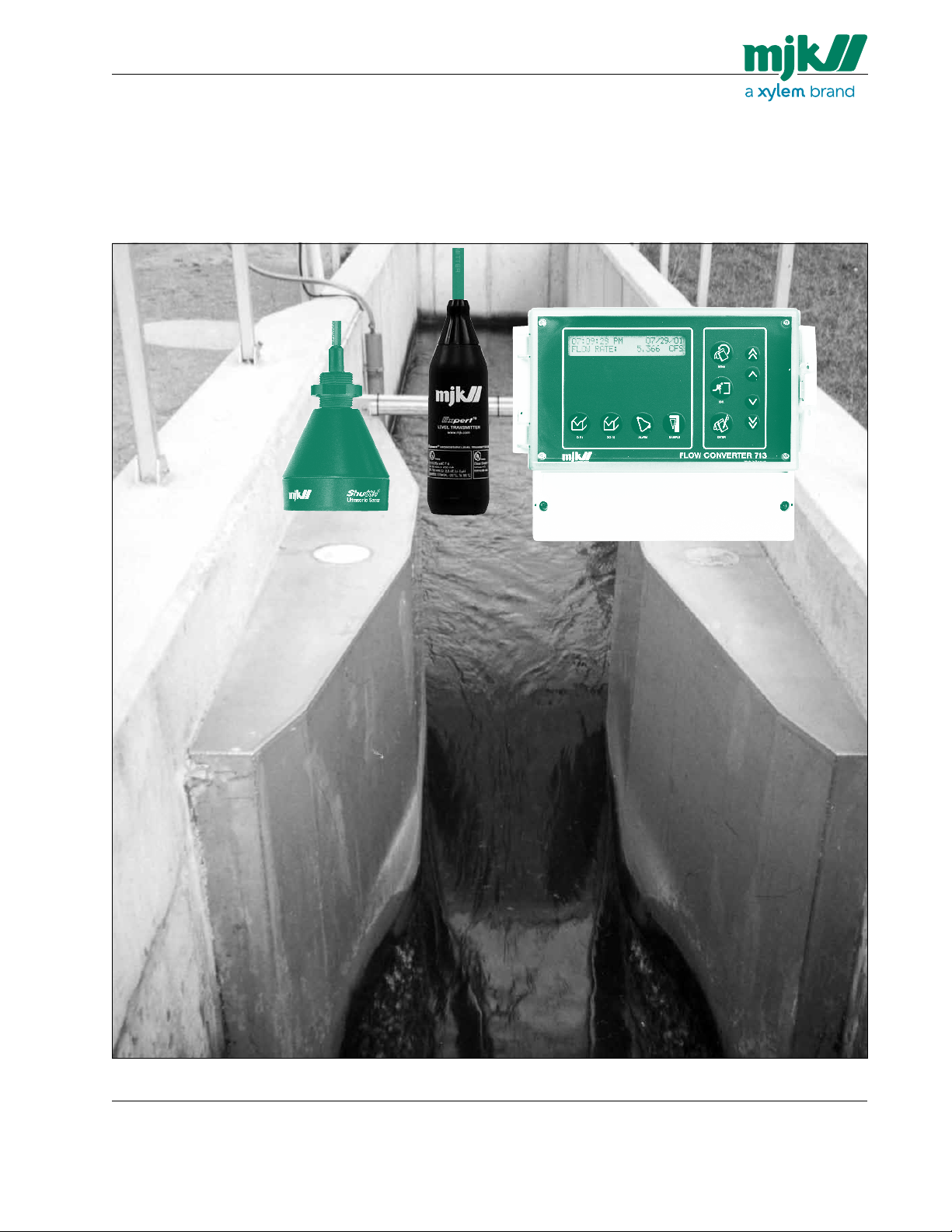
Open Channel Flowmeter
US 3.10 713 FLOW CONVERTER 1210 - SW 833062
1
MJK North America, Inc.
37 Sherwood Terrace, #126
Lake Bluff, Il 60044
Tel.: 847-482-8655
Fax: 847-482-8654
mjkusa@mjk.com
www.mjk.com

Manual
Declaration of Conformity
Konformitetserklæring
Vi, MJK Automation A/S,
DK-2850 Nærum, påtager os
det fulde ansvar for at produktet
Declaration of Conformity
We, MJK Automation A/S,
DK-2850 Nærum, declare under
our sole responsibility that the
product
Konformitätserklärung
Wir, MJK Automation A/S,
DK-2850 Nærum, erklären in
alleiniger Verantwortung, dass
das Produkt
MJK Expert Series 1400 / 3400 Pressure Level Transmitter
som denne erklæring angår,
er i overensstemmelse med
følgende standard(er) eller andre
normdokument(er).
EN60079.0:2006, EN60079.11:2007
EN61000-6-1:2007
EN61000-6-3:2007
efter bestemmelserne i
direktiv
2004/108/EC
Declaration de conformite
Nous, MJK Automation A/S,
DK-2850 Nærum, déclarons
sous notre seule responsabilité
que le produit
to which this declaration relates
is in conformity with the following
standard(s) or other normative
document(s).
EN60079.0:2006, EN60079.11:2007
EN61000-6-1:2007
EN61000-6-3:2007
following the provisions of
Directive
2004/108/EC
Dichiarazione di conformità
Noi, MJK Automation A/S,
DK-2850 Nærum, dichiariamo
sotto la nostra esclusiva responsabilità che l’apparecchio
auf das sich diese Erklärung
bezieht mit der/den folgenden
Nor me(en) oder normativen
Dokument(en) übereinstimmt.
EN60079.0:2006, EN60079.11:2007
EN61000-6-1:2007
EN61000-6-3:2007
Gemäss den Bestimmungen der
Richtlinie
2004/108/EC
Declaración de Conformidad
Nosotros, MJK Automation A/S,
DK-2850 Nærum, declaramos
bajo nuestra única responsabilidad que el producto
MJK Expert Series 1400 / 3400 Pressure Level Transmitter
auquel se réfère cette déclaration est conforme á la (aux)
norme(s) ou autre(s) document(s)
normatif(s)
EN60079.0:2006, EN60079.11:2007
EN61000-6-1:2007
EN61000-6-3:2007
conformément aux dispositions
de Directive
2004/108/EC
al quale questa dichiarazione si
riferisce, è conforme alla seguente normativa(e) standard o ad
altri documenti di normativa(e)
EN60079.0:2006, EN60079.11:2007
EN61000-6-1:2007
EN61000-6-3:2007
conformemente alla disposizioni
della Direzione
2004/108/EC
06.07.2011
Jens Kruse
UL Approvals
UL-CUL listed, File # E 194021 UL 508/c22: 2 No. 142-M1987.
US 3.10 713 FLOW CONVERTER 1210 - SW 833062
2
al cual se refiere esta declaración, está en conformidad
con la(s) siguente(e) norma(s) u
otros documentos normativos
EN60079.0:2006, EN60079.11:2007
EN61000-6-1:2007
EN61000-6-3:2007
según las disposiciones de la(s)
directiva(s)
2004/108/EC
MJK North America, Inc.
37 Sherwood Terrace, #126
Lake Bluff, Il 60044
Tel.: 847-482-8655
Fax: 847-482-8654
mjkusa@mjk.com
www.mjk.com

Manual
Contents
Introduction 5
Safety instructions 5
Repair 5
Hazardous areas 5
Product identification 6
Mounting 6
General 6
Explosion hazardous areas 6
Mechanical mounting 7
MJK 713 Flowmeter 7
®
Shuttle
Ultrasonic Sensor 7
Measuring distances for Parshall flumes 9
Measuring distances for Palmer & Bowlus flumes 9
Measuring distances for rectangular weirs 9
Measuring distances for V-notch weirs 9
Measuring along a wall or other plane 10
Flow measurement with smaller flumes / weirs 10
The spread of the ultrasonic signal 10
Measuring through a concrete deck 11
Measurement through a pipe for foam protection. 11
Model 3100 Hydrostatic Transmitter 12
Measuring distances for Parshall flumes 12
Measuring distances for Palmer & Bowlus flumes 12
Measuring distances for rectangular weirs 13
Measuring distances for V-notch weirs 13
US 3.10 713 FLOW CONVERTER 1210 - SW 833062
Electrical mounting 14
MJK 713 System Package 1 14
MJK 713 System Package 2 14
MJK 713 System Package 3 14
Cable extension 15
Ultrasonic sensor 15
Cutting the cable 15
Hydrostatic transmitter 16
Cutting the cable 16
Display and keyboard 17
Quick start 17
Initial startup 18
3
MJK North America, Inc.
37 Sherwood Terrace, #126
Lake Bluff, Il 60044
Tel.: 847-482-8655
Fax: 847-482-8654
mjkusa@mjk.com
www.mjk.com

Manual
Indications 19
Function keys 20
Flow key Q(t) 20
Totalizer key SQ(t) 20
Alarm key 21
Power loss alarm 21
Sample key 21
Menu key 22
System Configuration 23
1.0 Set basic parameters 23
1.1 Set date and time 23
1.2 Access code enabled/disabled 23
1.3 Enter new access code 23
1.4 Select unit measurement 23
1.5 Select unit volume 23
1.6 Select unit flow rate 23
2.0 Set sensor parameters 23
2.1.1 Distance from zero to bottom of sensor 23
2.1.2 Hydrostatic sensor range 23
2.2 Level averaging 23
3.0 Choose primary device 24
3.1 Parshall flumes 24
3.2 Palmer & Bowlus flumes 24
3.3 V-notch weir 24
3.4 Rectangular weir 24
3.4.1 With or without contraction 24
3.4.2 Rectangular weir crest width 24
3.5 Q(h) linearization 24
3.5.1 Number of Q(h) points 24
3.5.2 Select decimal point for the flow values 24
3.5.3 Linearization height value 24
3.5.4 Linearization flow value 24
3.6 Optional formula 24
3.6.1 Optional formula - enter exponent 24
3.6.2 Select decimal point for coefficient 24
3.6.3 Optional formula - enter coefficient 24
3.7 Flow range / level range 25
4.0 Set digital output parameters 25
4.1 Select digital outputs (1-5) 25
4.2 Select function for DO 25
4.3 Alarm flow rate low 25
4.4 Alarm flow rate high 25
4.5 Set volume between pulses 25
4.6 Digital output ON-time 25
4.7 Choose delay on signal 26
4.8 Digital output NC/NO 26
5.0 Analog output 0-20 / 4-20 mA 26
Menu chart 27
Indication menus 27
Configuration menus 27
Appendix 30
A Factory settings 30
B Trouble shooting 31
C Technical specifications 32
D Hardware adjustments 33
E System Package 2 Shuttle
®
used as signal amplifier 34
F Max. head to max. nominal flow 37
US 3.10 713 FLOW CONVERTER 1210 - SW 833062
4
MJK North America, Inc.
37 Sherwood Terrace, #126
Lake Bluff, Il 60044
Tel.: 847-482-8655
Fax: 847-482-8654
mjkusa@mjk.com
www.mjk.com

Manual
Introduction
Thank you for choosing an MJK 713 Open Channel Flowmeter.
The MJK 713 Open Channel Flowmeter is a high quality
flow measurement instrument, in which the relation
between functions, userfriendliness and precision is
optimum.
The MJK 713 Open Channel Flowmeter use either an
ultrasonic transmitter or a hydrostatic pressure
transmitter. This must be specified at time of ordering.
The MJK 713 Open Channel Flowmeter measures the
flow rate of water or wastewater in all types of open weirs
and flumes and provides a display of both current flow
rate and totalized flow.
Yet MJK 713 is simple to set up and use in almost all applications, we recommend that you read this manual thoroughly in order to gain full use from the equipment.
You can always contact your representative or the MJK
Service Hotline for advice and guidance. Also, take a look
at www.mjk.com for additional product and application
information.
MJK Automation A/S is a Xylem brand.
Safety instructions
1: Read this manual carefully.
2: Be aware of the environment on the installation site.
Wear necessary protective equipment and follow all
current safety regulations.
3: MJK 713 can provide a start signal for dangerous
machinery. Always ensure that
connected machinery and other equipment are ef-
fectively being put out of service (i.e. removal of main
fuses, lock main and/or security switches in off position) before commencing installation, fault finding,
service and maintenance work etc.
4A: MJK 713 model 2500: There is a risk of lethal
electrical chock from terminal 1 to 5 and L-0.
Be careful not to touch these while the unit is in service.
4B: MJK 713 model 3000: There is a risk of lethal
electrical chock from terminal L-0. Be careful not to
touch these while the unit is in service.
Repair
1: Repair of Ex approved equipment (ultrasonic trans-
mitter) must only be made by MJK or by a service
representative approved by MJK.
Hazardous areas
1: All current local and national standards, regulations
regarding installation and use of Ex or hazardous
zone approved equipment, certifications and safety
instructions for Ex equipment, that have been used
together with the installation of the Shuttle
®
ultra-
sonic transmitter must be strictly observed.
US 3.10 713 FLOW CONVERTER 1210 - SW 833062
5
MJK North America, Inc.
37 Sherwood Terrace, #126
Lake Bluff, Il 60044
Tel.: 847-482-8655
Fax: 847-482-8654
mjkusa@mjk.com
www.mjk.com
Manual
Product identification
General
A standard MJK 713 is delivered for two different measuring ranges (0 - 1 ft and 0 - 3 ft).
It is very important that the measuring range is correct
for the flume in question in order to obtain maximum
measuring accuracy.
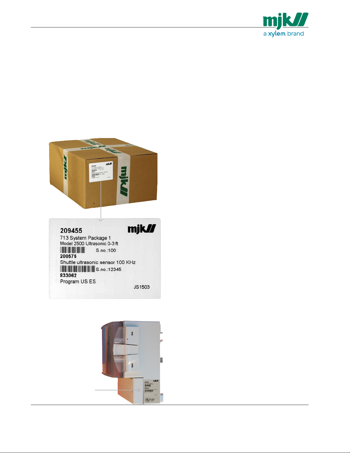
Check that the item(s) delivered corresponds to the ordered item(s). The item number is printed on a label that
is sticked onto the packing. Shown below is the label for
a MJK 713 System Package 1 delivery including a MJK
713 flowmeter and a Shuttle
®
ultrasonic sensor:
Mounting
General
MJK 713 measures the flow in an open flume or weir
based on the level of the head in the flume. The method
of measurement are based on the following mathematical
function:
x
Flow Q = f(head
× constant)
where the exponent x and the constant depends on the
type of weir or flume.
The flow converter has 3 different linearization
systems depending on how the volume of water is measured:
- preprogrammed formulas for different dimensions of
the most common flumes and weirs, Parshall flumes,
Palmer & Bowlus flumes, V-notch weirs, and rectangular weirs.
- for other flumes and weirs with a known calculation
formula the exponent and the factor of the calculation formula can be set.
- for flumes where no calculation formula exists, a
number of known flow values can be entered,
on which a point linearization and curve extrapolation
is calculated.
➀
➁
➁
➃
➀ Item number
➁ Item description
An identical marking can
be found on the right
hand side of the level
transmitter cabinet:
➂
➂
➂ Serial number
➃ Software version
It is obvious that the flow calculation is highly dependant
on the accuracy of the level measurement. It is therefore
important to follow the mounting instructions carefully for
the Shuttle
®
Ultrasonic Sensor (MJK 713 System Package 1 or 2) or MJK model 3100 Pressure Transmitter
(MJK 713 System Package 3).
Explosion hazardous areas
The Shuttle
®
ultrasonic sensor is Ex approved and can be
mounted in Zone 2 without the need of a
zener barrier. It is not approved for Class I Division I
zones.
The Flowmeter (= the electronic box with
display) must not be mounted in explosive
hazardous areas.
US 3.10 713 FLOW CONVERTER 1210 - SW 833062
6
MJK North America, Inc.
37 Sherwood Terrace, #126
Lake Bluff, Il 60044
Tel.: 847-482-8655
Fax: 847-482-8654
mjkusa@mjk.com
www.mjk.com
Manual
Mechanical mounting
MJK 713 Flowmeter
The MJK 713 Flowmeter is in NEMA 4X enclosure and
can be mounted outdoors directly on a wall or in a panel
using a panel mounting kit (order no. 200105). A sun
shield (order no. 200115) is recommended in very sunny
locations.
The MJK 713 Flowmeter must be
mounted vertically in order to observe the
NEMA4X standard.
Shuttle® Ultrasonic Sensor
The following are extremely important when
mounting the ultrasonic transmitter:
1: It should be mounted securely.
2: It should be mounted absolutely vertical.
Use a spirit level in TWO directions.
3: It should be mounted in the correct distance from
the bottom of the flume / weir.
Observe the blocking distance!
4: It should be mounted in the correct distance from
the inlet.
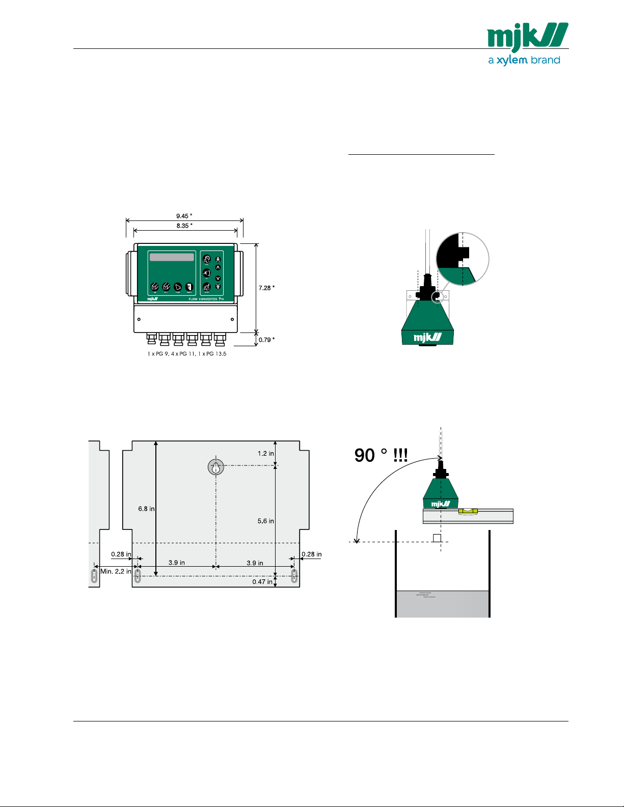
Mechanical dimensions for the MJK 713 Flowmeter.
The drawing below shows the drilling distances for
mounting the cabinet on a wall:
A full scale print of above drawing can be found at the
end of this manual.
1: The ultrasonic sensor is equipped with a nut for bracket
mounting. Note the recess on the nut - it must be fitted
safely in the bracket for firm fixing to the bracket:
2a: To ensure a reliable and precise level measurement it is
of vital importance that the ultrasonic sensor points down
absolutely vertical against the liquid surface.
US 3.10 713 FLOW CONVERTER 1210 - SW 833062
7
MJK North America, Inc.
37 Sherwood Terrace, #126
Lake Bluff, Il 60044
Tel.: 847-482-8655
Fax: 847-482-8654
mjkusa@mjk.com
www.mjk.com
Manual
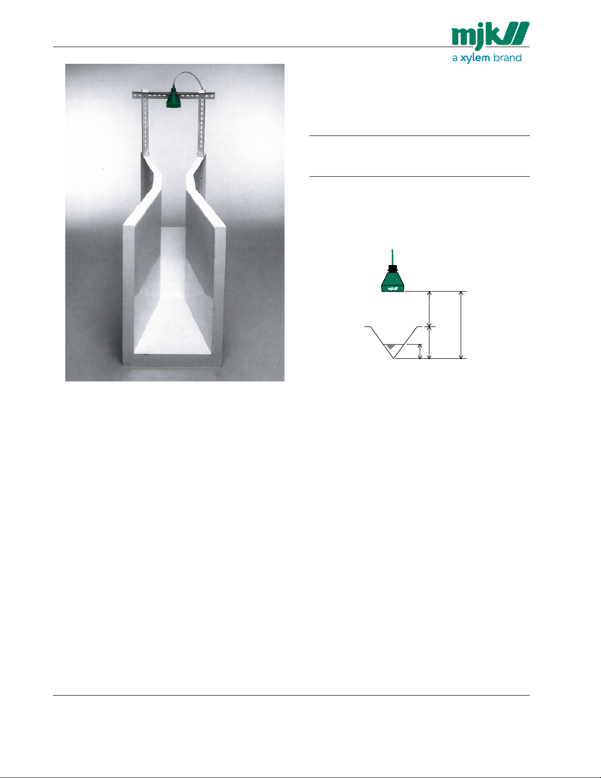
3: The ultrasonic sensor should be installed so that
the bottom of the sensor is as close as possible to
the max. height of the head but not closer than the
blocking distance.
Measuring range: 0 - 1’ 0 - 3’
Blocking distance: )* 16” 16”
Min. measuring range: 4” 12”
Max. measuring range: 12” 36”
Max. sensor height
)* 14” for System Package 2.
(w. Shuttle
➁: 30" 54"
®
Level Transmitter as signal amplifier.)
Maximum sensor height ➁ = Blocking distance ➀
+ measuring range ➃
➀
➁
2b: We deliver two types of sensor brackets that can be used
in almost any installation. The bracket shown is a flume
mounting bracket (order no. 200230 / 200235).
➃
➂
➀ Blocking distance ➁ Sensor height
➂ Actual measurement ➃ Measuring range
US 3.10 713 FLOW CONVERTER 1210 - SW 833062
8
MJK North America, Inc.
37 Sherwood Terrace, #126
Lake Bluff, Il 60044
Tel.: 847-482-8655
Fax: 847-482-8654
mjkusa@mjk.com
www.mjk.com
Manual
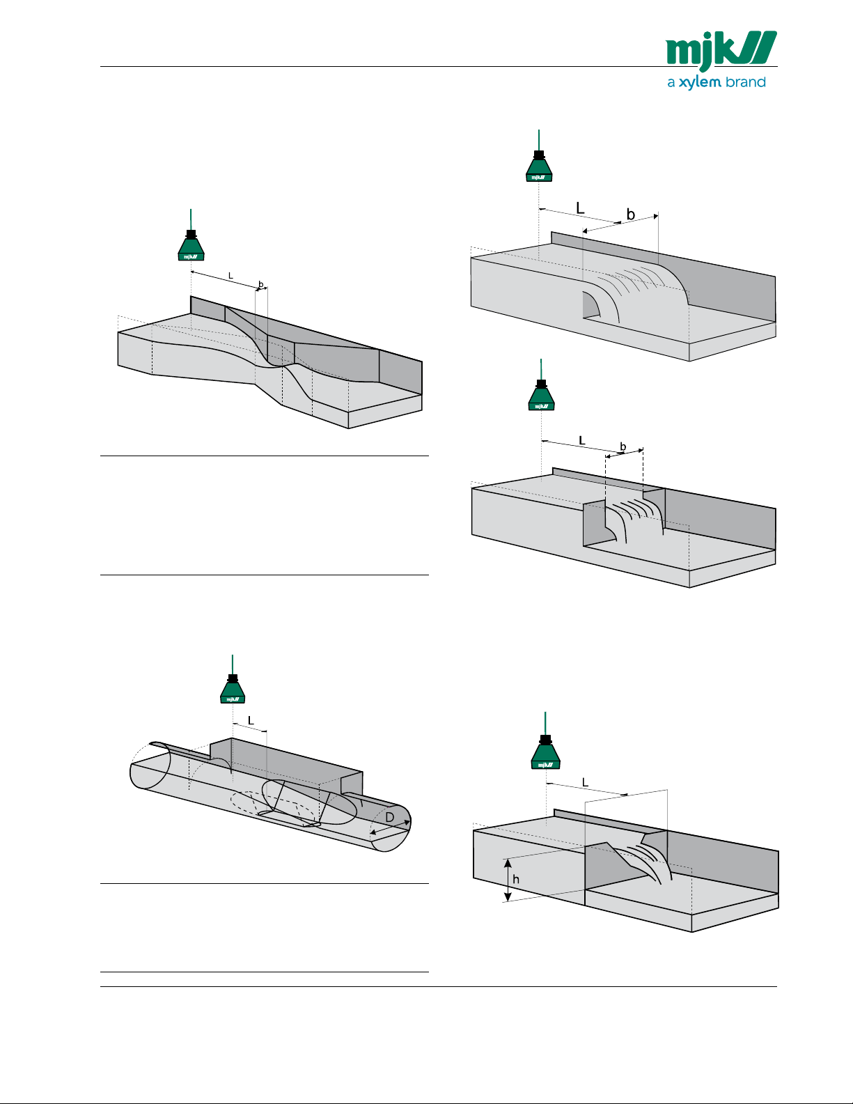
4: Mount the sensor in the correct upstream distance
from the head in the flume / weir.
The distance depends on the dimension and type
of flume / weir.
Measuring distances for Parshall flumes
Throat width b: Distance L: Throat width b: Distance L:
1” 10” 36” 43”
2” 11” 48” 47”
3” 12” 60” 51”
6” 16” 72” 56”
9” 23” 84” 59”
12” 36” 96” 63”
18” 37.5” 120” 72”
24” 39” 144” 80”
Measuring distances for rectangular weirs
- with and without side contraction
Measuring distances for Palmer & Bowlus flumes
Diameter D: Distance L: Diameter D: Distance L:
4” 2” 18” 9”
6” 3” 21” 10.5”
8” 4” 24” 12”
10” 5” 27” 13.5”
12” 6” 30” 15”
15” 7”
US 3.10 713 FLOW CONVERTER 1210 - SW 833062
(L = D/2)
The distance L should be between 4 to 5 times the nominal width b.
Measuring distances for V-notch weirs
The distance L should be between 3 to 4 times the
height h of the notch.
9
MJK North America, Inc.
37 Sherwood Terrace, #126
Lake Bluff, Il 60044
Tel.: 847-482-8655
Fax: 847-482-8654
mjkusa@mjk.com
www.mjk.com
Manual
Measuring along a wall or other plane
The values in table 1 assume the ultrasonic signal is sent
along a smooth surface like a wall or plane without any
projections, joints, butts etc.
If the surface is not smooth or has projections (i.e. joints
on prefab elements), the ultrasonic signal will be impedeaded too much, and for that reason
the values for minimum distance to wall in table 1 should
be increased with 50 - 100 % !
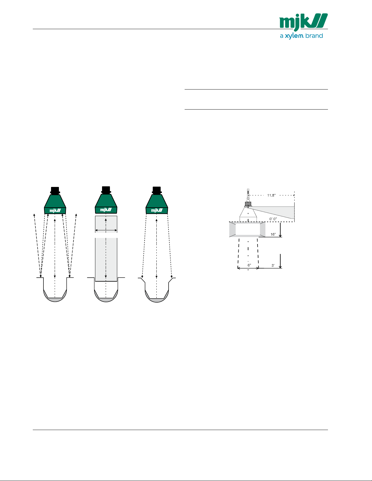
Flow measurement with smaller flumes / weirs
Smaller flumes may cause problems if the ultrasonic signal reflects on the edges of the flume as shown below
(fig. 2a).
The edges should be cut off (fig. 2c) or the ultrasonic
sensor should be mounted in a pipe (fig. 2b) with smooth
inner surface.
The spread of the ultrasonic signal
The table and illustration below show the spread of the
ultrasonic signal in conjunction to the measuring distance:
Measuring Beam Minimum distance to
SMOOTH
distance: spread: wall (from center line):
1’ 5” 2.3”
2’ 5” 2.6”
3’ 6” 2.9”
Table 1: The ultrasonic signal spread along a smooth wall and minimum
distance to center line in conjunction to the measuring distance.
Accordingly, as the measuring distance increases, the
distance from the center line to a smooth wall should also
be increased.
To avoid false echoes from e.g. edges, a minimum distance as shown on the drawing must be kept. The sensor
can be mounted in a smooth pipe if the distance cannot
be obtained. (See figure 1.)
(min. dia. 5 in)
A B C
Figure 2: Use a pipe (B) or cut off the edges (C) on small weirs to prevent
disturbing reflections from the flume edges.
Blocking
distance!
Figure 1: The signal spread in conjunction with the measurement distance. The
signal spread should be increased by 50 - 100 % if the surface is not
smooth!
US 3.10 713 FLOW CONVERTER 1210 - SW 833062
10
MJK North America, Inc.
37 Sherwood Terrace, #126
Lake Bluff, Il 60044
Tel.: 847-482-8655
Fax: 847-482-8654
mjkusa@mjk.com
www.mjk.com
Manual
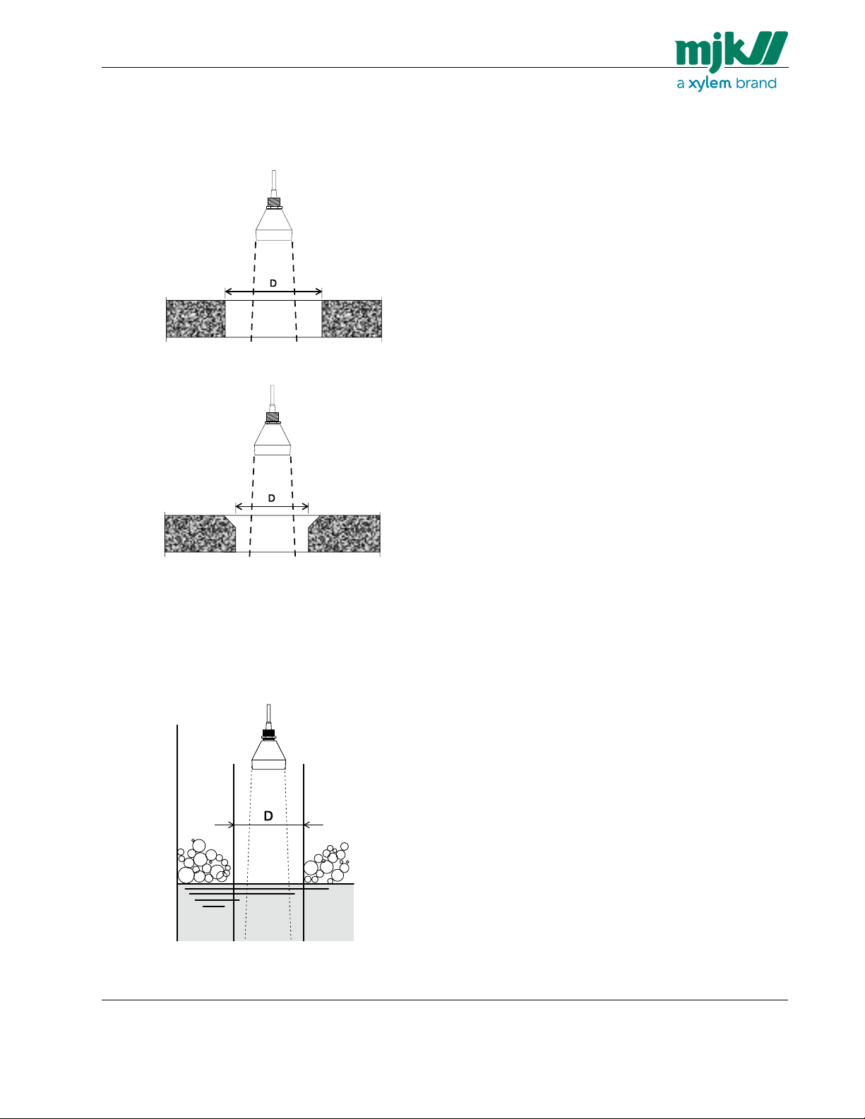
Measuring through a concrete deck
When the ultrasonic sensor is measuring through a concrete deck, the dimension of the opening should be made
as shown below: (See table 1 for the sensor spread.)
Min. diameter (D)
= sensor spread +
100 %
Measurement through a concrete deck with
Measurement through a concrete deck with
sharp edge.
Min. diameter (D) =
45 - 60 ° edge cutoff.
sensor spread
+ 50 %
Measurement through a pipe for foam protection.
When measuring on liquids prone to build up foam on the
surface, it can become necessary to measure through a
pipe, since the build up of foam rarely will occur inside the
pipe.
Measurement through a pipe for foam protection.
US 3.10 713 FLOW CONVERTER 1210 - SW 833062
Min. diameter (D)
= sensor spread +
100 %
11
MJK North America, Inc.
37 Sherwood Terrace, #126
Lake Bluff, Il 60044
Tel.: 847-482-8655
Fax: 847-482-8654
mjkusa@mjk.com
www.mjk.com
Manual
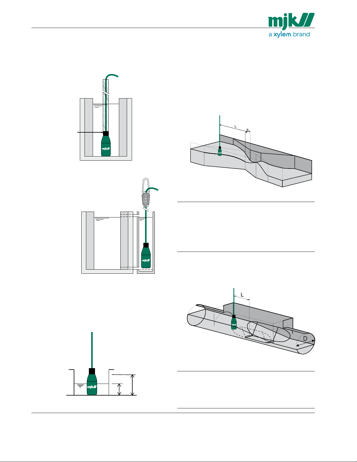
Model 3100 Hydrostatic Transmitter
The following directions should be followed when mounting the pressure transmitter:
1: It should be mounted securely - preferably on
a pipe.
1 in NPT thread
pressure transmitter from hurling around in a Parshall flume.
The use of a
stilling well is the
best option!
A 1 in pipe is used to prevent the
3: Mount the transmitter in the correct upstream
distance from the contraction in the flume / weir.
The distance depends on the dimension and type
of flume / weir.
4: Mount the transmitter at a location with no or very
little turbulence - preferably in a stilling well placed
in the correct distance from the contraction.
Measuring distances for Parshall flumes
Throat width b: Distance L: Throat width b: Distance L:
1” 10” 36” 43”
2” 11” 48” 47”
3” 12” 60” 51”
6” 16” 72” 56”
9” 23” 84” 59”
12” 36” 96” 63”
18” 37.5” 120” 72”
24” 39” 144” 80”
In case the water stream is so intense that the turbulence will affect the measuring
accuracy, the pressure transmitter must be placed in a stilling well. Note, that the
transmitter should be positioned in the stilling well at the same height as the
zero flow level!
2: It should be placed in the correct height over the
bottom of the flume / weir.
➁
➀
➀ Actual measurement
US 3.10 713 FLOW CONVERTER 1210 - SW 833062
➁ Measuring range
Measuring distances for Palmer & Bowlus flumes
A stilling well should always
be used together with a
pressure transmitter!
Diameter D: Distance L: Diameter D: Distance L:
4” 2” 18” 9”
6” 3” 21” 10.5”
8” 4” 24” 12”
10” 5” 27” 13.5”
12” 6” 30” 15”
15” 7”
12
(L = D/2)
MJK North America, Inc.
37 Sherwood Terrace, #126
Lake Bluff, Il 60044
Tel.: 847-482-8655
Fax: 847-482-8654
mjkusa@mjk.com
www.mjk.com

Manual
Measuring distances for rectangular weirs
- with and without side contraction
The distance L should be between 4 to 5 times the nominal width b.
Measuring distances for V-notch weirs
The distance L should be between 3 to 4 times the
height h of the notch.
US 3.10 713 FLOW CONVERTER 1210 - SW 833062
13
MJK North America, Inc.
37 Sherwood Terrace, #126
Lake Bluff, Il 60044
Tel.: 847-482-8655
Fax: 847-482-8654
mjkusa@mjk.com
www.mjk.com

Manual
Electrical mounting
MJK 713 must not be connected to the power supply
before the ultrasonic sensor / pressure transmitter is
mounted and connected correctly.
MJK 713 is supplied from the mains on terminal
“0” and “P”.
Current regulations for conductor and fuse dimensions
should always be observed.
MJK 713 System Package 1
MJK 713 2500 with ultrasonic sensor
Standard cable length 40 ft.
(Can be extended to max.150 ft. using
MJK no. 690010 cable.
No. 1 = brown
No. 2 = red
Ultrasonic Sensor
No. 3 = orange
No. 4 = yellow
No. 5 = black
Power
supply
Remove the lid to gain access to the terminals.
MJK 713 2500 Flowmeter
Relay out 1
Relay out 2
Relay out 3
Relay out 4
Current output
(0 / 4 - 20 mA)
Totalizer output
MJK 713 System Package 2
MJK 713 3000 with ultrasonic sensor using Shuttle® Level Transmitter as signal amplifier
®
Level Transmitter
Shuttle
MJK 713 3000 Flowmeter
Power
Ultrasonic Sensor
supply
By looping the 4-20 mA signal through one of the relay
outputs on the Shuttle
failure on the Shuttle® Level Transmitter will trig a
system failure message on the MJK 713. Note that
the Shuttle® must be programmed as described in
appendix E in order to achieve this function.
MJK 713 System Package 3
MJK 713 3000 with hydrostatic level transmitter
No. 1 = red
No. 2 = brown
No. 3 = black
Pressure Transmitter
Power
supply
Note: 1: Conduit hubs are to beconnected to the
conduit prior to the connection to the enclosure.
2: Terminal tightening torque = 0.5 Nm.
®
Level Transmitter, a system
US 3.10 713 FLOW CONVERTER 1210 - SW 833062
14
MJK North America, Inc.
37 Sherwood Terrace, #126
Lake Bluff, Il 60044
Tel.: 847-482-8655
Fax: 847-482-8654
mjkusa@mjk.com
www.mjk.com

Manual
Cable extension
One of the most common faults on a MJK 713
installation is bad or faulty cable connections.
It is recommended to use a MJK connection box if the
sensor cable must be extended.
Ultrasonic sensor
The Shuttle
®
ultrasonic sensor are standard de-livered
with 40 ft of cable. The ultrasonic sensor can be delivered with up to 150 ft of cable on order, or the standard
40 ft cable can be extended to max. 150 ft.
The cable is a special low capacity cable,
so extensions should always be made with
the same type of cable.
MJK Connection
Box (NEMA 4X),
order no. 200590.
To Shuttle®
ultrasonic
sensor
Max.
150 ft !
To MJK 713
flow meter
The cable is delivered with the wires stripped as shown
with the black wire (no. 5) soldered to the shield:
When the cable is cut, only 4 wires will appear:
The ultrasonic sensor cable has 5 wires with both color
code and number:
Number: Color: Designation:
1 Brown Ultrasonic pulse
2 Red
3 Orange Temperature compensation
4 Yellow
5 Black Shield )*
)* This wire is connected to the cable shield.
The wires are mounted according to the terminal markings on the connection box PCB and on the MJK 713
respectively.
Cutting the cable
When the cable has been cut, the shield
should be mounted in terminal 5 instead of
the black wire !
When the ultrasonic sensor is mounted and connected
correctly, the MJK 713 can be connected to the power
supply.
See section ‘Quick start’ on page 18.
US 3.10 713 FLOW CONVERTER 1210 - SW 833062
15
MJK North America, Inc.
37 Sherwood Terrace, #126
Lake Bluff, Il 60044
Tel.: 847-482-8655
Fax: 847-482-8654
mjkusa@mjk.com
www.mjk.com

Manual
Hydrostatic transmitter
The pressure transmitter are delivered with 40 ft of cable
as standard.
The cable can be lengthened with any type of cable using
MJK connection box 202922. Although the measuring
signal is not sensitive to electrical noise, we recommend
the use of a screened cable.
Ensure that no moisture can enter the pressure
compensation tube inside the cable.
MJK Connection
Box (NEMA 4X)
with vent plug,
order no 202922.
To MJK 713
flow meter
Max. loop resistance
600 Ω !
To pressure
transmitter
The factory delivered cable has three wires marked with
the numbers 1 - 2 - 3.
Number: Color: Designation:
1 Black Positive (+) wire
2 Black Negative (-) wire
3 Black Shield )*
4 - Air pressure compensation tube
)* This wire is connected to the cable shield.
The wires are mounted according to the terminal markings on the connection box PCB and on the MJK 713
respectively.
Take care not to block or squeeze the air pressure
compensation tube ➃.
When the cable is cut, 7 wires will appear:
➂
When the cable has been cut, the shield
should be mounted in terminal 3 instead of
the black wire !
The small-gauged colored wires MUST NOT be used or
short circuited as it may damage the pressure transmitter.
The colored wires should be cut off in different lengths
to prevent them from short circuit.
See also separate instruction manual for the MJK pressure transmitter.
When the pressure transmitter is mounted and connected
correctly, the MJK 713 can be connected to the power
supply.
See section ‘Quick start’ on page 18.
Cutting the cable
The cable is delivered with the wires stripped as shown
with wire no. 3 soldered to the shield:
➃
➂
➁
➀
US 3.10 713 FLOW CONVERTER 1210 - SW 833062
16
MJK North America, Inc.
37 Sherwood Terrace, #126
Lake Bluff, Il 60044
Tel.: 847-482-8655
Fax: 847-482-8654
mjkusa@mjk.com
www.mjk.com

Manual
Display and keyboard
Display
2 x 24 character backlit display for indication
of menus and values.
ESCape
This key allows you to change back to the main
menu or to undo a new choice. By pressing
the ESCape button two or three times, you will
return to the function indications. If you think
you are lost, or you think you made a mistake,
simply press this button a few times to start over.
However, the escape function is disabled when
choosing primary device.
MENU
By pressing the MENU key,
the display will change to
the next main menu.
Arrow keys
The arrow keys are used
for changing a current
setting.
Pressing the arrow keys
change the values up
or down. By pressing
the ”up” arrow keys, the
number in the display will
increase.
Pressing the ”down”
arrow keys will decrease
the value.
ENTER
This key allows you to
change between the main
menu to a sub-menu, as
well as between submenus.
The key also allows you
to confirm the choice
from a sub-menu.
Q(t)
Registers for flow rate:
- instantaneous value
- average flow rate for
the last 1 hour
- average flow rate today
- average flow rate for
the last 24 hours
Σ Q(t)
Registers for:
- total flow
- total flow 1 hour
- total flow today
- total flow 24 hours
- 99 days log
Quick start
When MJK 713 is powered up for the first time, a quick
setup sequence will be initiated that will guide you
through the following basic settings needed for most
installations:
1: selection of primary device / flow calculation
formula
2: max. flow range
3a: ultrasonic transmitter distance
(applies to MJK 713 2500 /
System Package 1 only)
US 3.10 713 FLOW CONVERTER 1210 - SW 833062
ALARM
Alarm record with the previous nine alarms incl. date
and time of occurrence.
SAMPLE
Registration of:
- total number of samples
- number of samples today
- number of samples within the
last 24 hours
3b: hydrostatic sensor range
(applies to MJK 713 3000 /
System Package 2 & 3 only)
After these initial settings has been made, MJK 713 will
automatically begin to measure flow. If you wish to take
advantage of the flow converter’s many other advanced
functions, such as flow proportion sampling, the remaining sections of this manual will help you to configure the
unit.
17
MJK North America, Inc.
37 Sherwood Terrace, #126
Lake Bluff, Il 60044
Tel.: 847-482-8655
Fax: 847-482-8654
mjkusa@mjk.com
www.mjk.com

Manual
Initial startup
MJK 713 will show the following display at power-up:
MJK 713 initiates the quick setup sequence after app. 30
sec:
The following menus is only shown the first time MJK 713
is powered up and will not appear again after the initial
quick setup sequence unless the quick start sequence is
initiated again by holding ALARM + SAMPLE simultaneously and pressing
ENTER while in level readout menu.
This is shown when ENTER is pressed the first time.
1:
Select flume/weir or flow calculation formula with arrow
keys and confirm with ENTER. Choose between Parshall
flume, Palmer & Bowlus flume, V-notch weir, rectangular
weir or optional formula.
The max. flow range determines the range of the mA output. MJK 713 will calculate the max. level based on the
desired max. flow for the selected primary device, and
set the analog output to give out 20 mA at the max. flow.
(The setting is also used internally to monitor the functions of the flow meter.)
This menu will appear for a MJK 713 2500 /
System Package 1:
3a:
Set the distance from the zero point (= zero flow level in
flume/weir) to the bottom of the ultrasonic sensor with the
arrow keys and confirm with ENTER.
Distance from zero
point to bottom of
sensor
This menu will appear for a MJK 713 3000 /
System Package 2 & 3:
Depending on the selection of flume/weir type or calculation method, a number of menus for setting some specific
information may appear.
No matter which primary device being selected, the following will be displayed as the last:
2:
In this menu the maximum flow for the selected primary
device should be set in accordance with the value stated
in the tables in Appendix E.
It is very important to set the correct maximum
flow value, since it will dramatically reduce
measuring errors!
Set the desired max. flow range for the installation with
the arrow keys and confirm with ENTER.
MJK 713 will now calculate the max. level related to the
selected primary device and display the result in in the
second line.
3b:
Set the measuring range for the hydrostatic pressure
transmitter with the arrow keys and confirm with ENTER.
The basic data entries is now finished and MJK 713
starts
to measure the flow.
To take advantage of MJK 713’s many advanced functions, please see the system configuration section starting on page 23.
Note: For System Package 2 (MJK 713 3000 with
®
Shuttle
Level Transmitter as signal amplifier:
See appendix E for the necessary settings for
the Shuttle
®
Level Transmitter
Note: “Quick Start” sequence can be initiated again
by holding ALARM + SAMPLE simultaneously
and pressing ENTER while in level readout
menu.
US 3.10 713 FLOW CONVERTER 1210 - SW 833062
18
MJK North America, Inc.
37 Sherwood Terrace, #126
Lake Bluff, Il 60044
Tel.: 847-482-8655
Fax: 847-482-8654
mjkusa@mjk.com
www.mjk.com

Manual
Indications
At the front of the flow converter, there are 4 function
keys: the flow rate key Q(t), the totalizer key Σ Q(t), the
alarm key ALARM and the sample key SAMPLE.
When one of these keys is pressed one or more times,
the different function menus appear. The menus available
depend on how you configure the flow converter.
Configuring the flow converter is accomplished in the
configuration menus, which in turn are divided into several sub-menus. You gain access to the configuration
menus by pressing the MENU key. In each menu the different settings are obtained by pressing the arrow keys.
Note: A complete diagram of the menus can be
found in the back of this manual. This diagram
will be very helpful to you if you choose to
configure the flow converter!
Flow Key.
See also page 20.
Totalizer Key.
See also page 20.
99 x 24
hours log
US 3.10 713 FLOW CONVERTER 1210 - SW 833062
Alarm Key.
See also page 21.
Last 9 alarm log.
19
Sample Key.
See also page 21.
MJK North America, Inc.
37 Sherwood Terrace, #126
Lake Bluff, Il 60044
Tel.: 847-482-8655
Fax: 847-482-8654
mjkusa@mjk.com
www.mjk.com

Manual
Function keys
Flow key Q(t)
This key shows the values of the relevant flow, as well as
various average values.
F1 Flow
Press once for:
Here the instantaneous actual flow is shown. The flow is
calculated from the chosen Q(h)-formula. Measuring value
with time and date is indicated.
F2 Average flow 1 HR
Press twice for:
Here the average flow for the last full hour is indicated.
F3 Average flow today
Press three times for:
Totalizer key SQ(t)
This key will give access to indication of summed quantities.
F5 Totalizer
Press once for:
Here the total quantity is indicated, from when the value
was last reset. The quantity is updated every second
and is indicated with time and date. The value is reset by
pressing ENTER.
F6 Totalizer 1 hour
Press twice for:
Here the summed quantity for the previous full hour is indicated (e.g. 11:00AM -12:00PM).
F7 Totalizer today
Press three times for:
Here the average flow from 12:00:00AM to the current
time is indicated. The display is updated every second.
F4 Average flow 24 HR
Press four times for:
Here the average flow for the last full 24 hours is indicated
(12:00:00AM to 11:59:59PM).
US 3.10 713 FLOW CONVERTER 1210 - SW 833062
Here the summed quantity for today is indicated. The result along with the time interval is updated every second.
The value is reset by pressing ENTER.
F8 Totalizer 24 hour 99 days log
Press four times for :
Here the 24 hours summed quantity log is indicated. The
quantity and the date for the previous day are logged every 24 hours (12:00:00AM). The log goes back 99 days.
The arrow keys are used for accessing the log.
Note, that the MJK 713 must have been in service for
at least 24 hrs before the last 24 hr log will contain valid
data, and at least 99 days before the full 99 days log will
contain valid data.
20
MJK North America, Inc.
37 Sherwood Terrace, #126
Lake Bluff, Il 60044
Tel.: 847-482-8655
Fax: 847-482-8654
mjkusa@mjk.com
www.mjk.com

Manual
Alarm key
The digital outputs can be configured as alarms of one of
the following alarm types: high flow, low flow and sensor
error. In addition a Power Loss alarm is generated if the
power supply to the flow converter is interrupted. Press
the alarm key to see the previous nine alarms. A new
alarm is registered as alarm no 1, the other alarms are
moved one place, and the alarm which was previously
registered as alarm no 9 is erased.
F9 Alarm display
After pressing the key once alarm no. 1 is shown, which
is the latest alarm; press again and alarms 2-9 come up.
By using the arrow keys it is possible to move backwards
and forwards between the alarms.
The instant an alarm is registered, the alarm type, the
digital output and the time is shown on the display:
When the alarm is no longer active, the time of switch
off is registered. Beware that different alarms could have
been activated in the meantime, meaning the alarm is no
longer no. 1:
Sample key
If one or more of the digital outputs are configured for
controlling a sampler, pressing this key will give following
indications:
F10 Number of samples
Press once for:
This display indicates how many samples have been
taken since last reset or system start up. Press ENTER
for reset, see menu F13.
F11 Number of samples today
Press twice for:
This display indicates how many samples have been
taken today (12:00 AM - now). Press ENTER for reset,
see menu F13.
F12 Number of samples 24 HR
Press three times for :
Power loss alarm
Start of power loss is registred with a precision of 5 min.
End of power loss is registred when the flowmeter is
powered up.
The upper line in the display shows the time for starting
the alarm. The bottom line shows the time for stop. When
an alarm is detected only the time for start is shown in the
upperline of the display, signaling that the alarm has not
disappeared.
When a new alarm appears the display will change from
the previous chosen main menu to F9 - alarm indication,
alarm.
US 3.10 713 FLOW CONVERTER 1210 - SW 833062
This menu indicates how many samples were taken
yesterday. Value and date for the previous 24 hours are
indicated.
F13 Reset
Some counter values can be set at 0-level by using the
enter key. One of the following menus will appear:
When a counter has reached its max. value a negative
number is shown. Then reset the counter as described in
F13.
21
MJK North America, Inc.
37 Sherwood Terrace, #126
Lake Bluff, Il 60044
Tel.: 847-482-8655
Fax: 847-482-8654
mjkusa@mjk.com
www.mjk.com

Manual
Menu key
This key gives access to the configuration menus with
readout and programming of the submenus.
A selection is made with the arrow keys (up or down) and
confirmed with the “ENTER” key. Non-confirmed selections will flash in the display, whereas a current/confirmed
selection in shown non-flashing.
Level
Press MENU once for:
Here the measured level (LEVEL) and the value for the
analogue output (I) is indicated. The digital
outputs are indicated as D1-D5. “0” indicates nonactivated output, whereas “1” indicates activated
outputs.
Access denied
What happens when the wrong access code is keyed in:
It will not be possible to make changes in the setup. Return to the previous chosen menu by pressing the ESC
key once.
Language
Press MENU twice for:
Change the language with the arrow keys and confirm
with ENTER.
Enter access code
Press MENU three times for:
The remaining configuration menus can be protected with
a 4-digit access code. Enter the access code with the arrow keys and press “ENTER”. Double
arrows changes the first two digits, single arrows changes the last two digits.
When the access code is keyed in, access to the remaining configuation menus will be given for 5 min. since last
key pressed.
The access code 1111 can always be used.
US 3.10 713 FLOW CONVERTER 1210 - SW 833062
22
MJK North America, Inc.
37 Sherwood Terrace, #126
Lake Bluff, Il 60044
Tel.: 847-482-8655
Fax: 847-482-8654
mjkusa@mjk.com
www.mjk.com

Manual
System Configuration
1.0 Set basic parameters
Access to the configuration menus are obtained by
pressing ENTER twice.
1.1 Set date and time
Time and date is adjusted with the arrow keys, followed
by ENTER.
1.2 Access code enabled/disabled
The remaining configuration menus can be protected by
an access code to prevent unauthorized access to the
configuration menus. It will still be possible to
operate MJK 713’s normal functions and readouts. Select
function with the arrow keys and confirm with ENTER.
1.3 Enter new access code
If access code is enabled this menu displays a
chosen access code (4 digits) for access to the configuration menus. Double arrows changes the first two digits,
single arrows changes the last two digits. Change the
code and confirm with ENTER.
1.4 Select unit measurement
Level indication and unit of elevation can be chosen as:
m, cm, mm, ft, in
Select with the arrow keys and confirm with ENTER.
2.0 Set sensor parameters
Access is obtained by pressing ENTER. Press MENU
once to enter the main menu.
2.1.1 Distance from zero to bottom of sensor
(MJK 713 2500 only.)
Enter the distance from the bottom of the ultrasonic sensor to the actual zero point. Double arrows changes the
first two digits, single arrows changes the last two digits.
Set the distance and confirm with
ENTER.
2.1.2 Hydrostatic sensor range
(MJK 713 3000 only.)
Select the measuring range for the hydrostatic
sensor with the arrow keys and confirm with ENTER.
Zero level for Palmer & Bowlus flume.
1.5 Select unit volume
The unit for volume can be chosen between:
m
3
, Gal, CF
Select with the arrow keys and confirm with ENTER.
1.6 Select unit flow rate
The unit for flow can be chosen between:
l/s, m
US 3.10 713 FLOW CONVERTER 1210 - SW 833062
3
/h, GPM, CFS, MGD
Zero level for Parshall flume.
2.2 Level averaging
This menu sets the interval for averaging the level measurement. The interval can be set between 1 and 60 seconds. Select the interval with the arrow keys and confirm
with ENTER.
23
MJK North America, Inc.
37 Sherwood Terrace, #126
Lake Bluff, Il 60044
Tel.: 847-482-8655
Fax: 847-482-8654
mjkusa@mjk.com
www.mjk.com

Manual
3.0 Choose primary device
Select the type of flume/weir or flow calculation formula.
6 options are available: Parshall flume, Palmer & Bowlus
flume, V-notch weir, rectangular weir, linearization and optional flow formula. Select the desired flume/weir or flow
calculation formula with the arrow keys and confirm the
selection with ENTER.
Note that entering this menu will force you to go through
all submenus concerning the selected flume / flow calculation formula.
3.1 Parshall flumes
For Parshall flumes there is a choice between the
following standard sizes: 1”, 2”, 3”, 6”, 9”, 12”, 18”, 24”,
36”, 48”, 60”, 72”, 96”, 120”, and 144”.
Select the size with the arrow keys and confirm with ENTER.
3.2 Palmer & Bowlus flumes
For Palmer & Bowlus flumes there is a choice between
the following standard sizes: 4”, 6”, 8”, 10”, 12”, 15”, 18”,
21’’, 24”, 27” and 30”. Select the size with the arrow keys
and confirm with ENTER.
3.3 V-notch weir
Set the notch angle
with the arrow keys and confirm with ENTER.
3.4 Rectangular weir
Select this menu for rectangular weirs with and without
side contraction.
3.4.1 With or without contraction
Select if the weir has a contraction or not.
See also page 9.
α between 22,5 and 120 degrees
3.5.2 Select decimal point for the flow values
Select the decimal point and 10/100/1000 multiplier for
the flow points between
X.XXXX and XXXXX000
with the arrow keys and confirm with ENTER.
3.5.3 Linearization height value
Set the level [h] for a Q(h) point with the arrow keys and
confirm with ENTER. The level unit will be the unit selected in menu 1.4.
Note: Always start with the lowest value, then the next
and so on until the largest value is reached. The height 0
has a default flow of 0. The highest Q(h)-point automatically gives the measuring range.
The level value can be set within the level span.
3.5.4 Linearization flow value
Set the volume [Q] for the corresponding Q(h)-point with
the arrow keys and confirm with ENTER. The volume
MUST be greater than the value previously entered. The
volume unit will be the unit selected in menu 1.6.
3.6 Optional formula
This menu is used for entering the coefficient K and expo-
X
nent
in the basic flow formula Q(h) = K x hX.
Q is the flow in the chosen flow unit, h presents the level
in the chosen measurement unit, K is a factor between
0.000,01 and 6,500,000 and x is the exponent between
1 and 3.
3.6.1 Optional formula - enter exponent
Set the exponent
x
for the flow calculation formula with
the arrow keys and confirm with ENTER. Double arrow
changes the value fast and single arrow changes the
value slowly.
3.4.2 Rectangular weir crest width
Set the width b (see page 9) of the weir and confirm with
ENTER.
3.5 Q(h) linearization
This menu is used for entering a customized Q(h) linearization based on up to 10 linearizatioin points.
3.5.1 Number of Q(h) points
Enter the number (from 1 to 10) of Q(h)-points for the linearization with the arrow keys and confirm with ENTER.
The selected number of Q(h) points decides how many
times the menus 3.5.3 to 3.5.4 will appear.
US 3.10 713 FLOW CONVERTER 1210 - SW 833062
3.6.2 Select decimal point for coefficient
Select the decimal point / leading zero for the coeficient
for the flow formula. Select between
0.XXXXX and XXXXX
with the arrow keys and confirm with ENTER.
3.6.3 Optional formula - enter coefficient
Set the factor K with the arrow keys an confirm with ENTER. The factor can be set within 0.00001 to 6,500,000.
24
MJK North America, Inc.
37 Sherwood Terrace, #126
Lake Bluff, Il 60044
Tel.: 847-482-8655
Fax: 847-482-8654
mjkusa@mjk.com
www.mjk.com

Manual
3.7 Flow range / level range
This menu is mainly used to set the span of the mA output in relation to the calculated flow, but can also be used
to check the flow calculation in relation to the measured
level based on the formula for the
selected primary device / flow calculation.
Simply enter the flow with the arrow keys and press ENTER, and MJK 713 calculates the corres-ponding level.
The mA output span is set by entering the flow value
where the mA output should give out 20 mA.
An example: If a 12” Palmer & Bowlus flume is
selected as primary device, the nominal maximum flow
will be 881 GPM at a level of 9.1 in.
If the flow range value is set to 881 in this menu, MJK
713 calculates the level, the mA output will give out 20
mA at max. nominal flow and 4 / 0 mA at zero flow.
If the flow range value is changed to 400 GPM, the mA
output will give out 20 mA at 400 GPM and upwards and
4 / 0 mA at zero flow.
4.0 Set digital output parameters
Press ENTER for configuring digital outputs or press
MENU for MAIN MENU
4.1 Select digital outputs (1-5)
Configuring of the five digital outputs. Select with the arrow keys which digital output to program, confirm with
ENTER.
Digital output 5 (DO5) is output for an external counter.
4.2 Select function for DO
For digital output 1-4 select with arrow keys between
various functions: counter output, sampler, flow > 0%,
flow high, flow low and alarm sensor error. The choice is
confirmed with ENTER.
Counter output: After a preset quantity the output is
activated to trig an external counter.
Sampler: After a preset quantity the output is
activated to trig a sampling device or a
chemical dosing device.
Flow > 0%: Signal to indicate that the flow is greater
than 0 is applied, i.e. when measuring
emergency stormflow.
Flow rate high: Activated if flow exceeds a given flow
rate.
Flow rate low: Activated if flow drops below a given flow
rate.
Sensor error: Activated at sensor error. Factory default
is 5 minutes without an approved sensor
signal.
Output disabled: Output not used.
US 3.10 713 FLOW CONVERTER 1210 - SW 833062
4.3 Alarm flow rate low
The limit for flow low is keyed in using the arrow keys.
The span is 0 - 90 % of max. flow.
4.4 Alarm flow rate high
The limit for high flow is keyed in using the arrow keys.
The span is 10 - 100 % of max. flow.
4.5 Set volume between pulses
The volume that passes between each time a pulse is
sent to a DO is keyed in. The interval between the pulses
is limited to min. 1 sec.
4.6 Digital output ON-time
The ON time for the DO is keyed inusing the arrow keys.
Double arrow changes the value fast with 1 sec. jumps.
Single arrow changes the value slowly with 0.1 sec.
jumps. The range is 0.1 - 30 sec.
25
MJK North America, Inc.
37 Sherwood Terrace, #126
Lake Bluff, Il 60044
Tel.: 847-482-8655
Fax: 847-482-8654
mjkusa@mjk.com
www.mjk.com

Manual
4.7 Choose delay on signal
The time limit for an alarm must be exceeded before a
DO is activated.
The format is as follows - min:ss The maximum delay is
99 minutes and 59 seconds.
4.8 Digital output NC/NO
The relay function for digital output is keyed in, as Normally Open (NO) or Normally Closed (NC). Select with arrow keys, confirm with ENTER.
5.0 Analog output 0-20 / 4-20 mA
Select between 0-20 or 4-20 mA output. Select with arrow keys, confirm with ENTER.
US 3.10 713 FLOW CONVERTER 1210 - SW 833062
26
MJK North America, Inc.
37 Sherwood Terrace, #126
Lake Bluff, Il 60044
Tel.: 847-482-8655
Fax: 847-482-8654
mjkusa@mjk.com
www.mjk.com

Manual
Menu chart
Indication menus Configuration menus
Flow rate key
Press 1 X: Average flow rate 1 hr
Press 2 X: Average flow rate today
Press 3 X: Average flow rate 24 hr
Totalizer key
Press 1 X: Totalizer 1 hr
Press 2 X: Totalizer today
Press 3 X: Totalizer last 24 hr
In the last selection the
totalizer values for the last 99
days can be displayed using
the arrow keys.
Alarm key
Press 1 X for alarm list with
last 9 alarm log.
Toggle alarms
with arrow keys.
Sampler key
Press 1 X: Total number of samples
Press 2 X: Number of samples today
Press 3 X: Number of samples last 24 hr
US 3.10 713 FLOW CONVERTER 1210 - SW 833062
27
MJK North America, Inc.
37 Sherwood Terrace, #126
Lake Bluff, Il 60044
Tel.: 847-482-8655
Fax: 847-482-8654
mjkusa@mjk.com
www.mjk.com

Manual
Configuration menus
1.0
1.1
1.2
1.3
1.4
1.5
1.6
2.0 3.0
2.1.1
2.1.2
2.2
3.1 3.2 3.3
US 3.10 713 FLOW CONVERTER 1210 - SW 833062
28
3.7
MJK North America, Inc.
37 Sherwood Terrace, #126
Lake Bluff, Il 60044
Tel.: 847-482-8655
Fax: 847-482-8654
mjkusa@mjk.com
www.mjk.com

Manual
Configuration menus
4.0 5.0
4.1
4.2
4.5
4.6
3.4 3.5 3.6
4.3
4.4
4.7
4.8
3.4.1 3.5.1 3.6.1
3.4.2 3.5.2 3.6.2
US 3.10 713 FLOW CONVERTER 1210 - SW 833062
3.5.3 3.6.3
3.5.4
29
MJK North America, Inc.
37 Sherwood Terrace, #126
Lake Bluff, Il 60044
Tel.: 847-482-8655
Fax: 847-482-8654
mjkusa@mjk.com
www.mjk.com

Manual
Appendix A
Factory settings
Basic parameters: Factory setting: Current settings:
Access Code: Disabled (Code: 1111)
Measurement Level: Inches
Measurement Volume: Gallons
Measurement Flow: MGD
Sensor distance: 30 in / 54 in*
Averaging of Level: 1 sec.
Range for flow: 1,000 MGD / 10.00 MGD*
Flow Calculations
Parshall Flume: 6’’ range (10 in):
Palmer & Bowlus Flume: 10’’ range (10 in):
V-notch: 90 °
Rectangular Crest width = 10.00 in
Optional Formula: Exponent = 1.000,
Factor= 0.100
Digital output
DO1: Disabled
(On-time = 0.5 sec)
DO2: Disabled
(On-time = 0.5 sec)
DO3: Disabled
(On-time = 0.5 sec)
DO4: Disabled
(On-time = 0.5 sec)
DO5: Counter 10.000/100.000 GAL*
On-time = 0.5 sec
Analog output
AO: 4 - 20 mA
* Depending on measuring range.
US 3.10 713 FLOW CONVERTER 1210 - SW 833062
30
MJK North America, Inc.
37 Sherwood Terrace, #126
Lake Bluff, Il 60044
Tel.: 847-482-8655
Fax: 847-482-8654
mjkusa@mjk.com
www.mjk.com

NOITACIDNI KCEHC YDEMER/ESUAC
siyalpsidehT
tilton
ylppusrewoP gnitnuomeriW ylmrifdaelehtdnadevomernoitalusniehtfoni¼muminimerA
?detnuom
ylppusrewoP '0'dekramslanimretneewtebtneserpegatloveviltcerrocehtsI
?'P'dna
?tcatni)CAV511@Am002(esufyramirpUSPehtsI
dnalenaptnorfehtmorfswercsgniniaterruofehtevomeR
edisdnahtfelehtnodetacolsiesufehT.lenaptnorfehtevomer
.yrassecenfiegnahcxE.BCPrewolehtnoremrofsnartehtwoleb
317 setacid
ni
rorremetsys
ecafrusdiuqiL htgnertslangiS ?ymaofecafrusdiuqilehtsI
ehtgninrutyblangiscinosartluehtfohtgnertsehtgnisaercniyrT
.esiwkcolcretemoitnetop'niaG'
dnalenaptnorfehtmorfswercsgniniaterruofehtevomeR
rewolehtnodetacolsiretemoitnetopehT.lenaptnorfehtevomer
.Dxidneppaees-BCP
gnigarevaleveL ?ydaetsnuecafrusdiuqilehtsI
.2.2noitcesees-gnigarevalevelrofgnittesehtgnisaercniyrT
elttuhS
®
cinosartlU
-rosneS
erusserP
rett
imsnarT
gnitnuomeriW noitcennoceeS?slanimrettcerrocehtotdetcennocseriwehterA
.margaid
snoisnetxeelbaC ?snoitcennocehtniretawerehtsI
.htgneldnaepytelbackcehC?yltcerrocedamsnoisnetxeehterA
nehwxobnoitcennocssofnaDaesuotdednemoccersitI
.selbacgnidnetxe
elttuhS
®
cinosartlU
rosneS
noitidnoC ?dekcarcroderuolocsimrosnesehtfotrapkcalbehtsI
ehtrofdetiustonsirosnesehttahtsetacidnigniruolocsiM
.etisnoitallatsniehtnotnemnori
vne
noitcnuF sirosneseht,tonfI?sdnuosgnikcilcgnittimsnartrosnesehtsI
.ytluaf
gnitnuomrosneS ?LACITREVYLETULOSBAdetnuomrosnesehtsI
anidetnuomylmrifsirosnesehttahttnatropmiylemertxesitI
elttuhSfognitnuomlacinahceM'noitceseeS.noitisoplacitrev
®
.'rosneScinosartlU
ecnatsidgnirusaeM 61nahteromsiecnatsidgnirusaemehtosdetnuomrosnesehtsI
?tf3/tf1nahtsseldnani
ebtontsumegnargnirusaemmuminim/mumixamehT
.dedeecxe
tuo-daerle
veL
tonsi
gnignahc
elttuhS
®
cinosartlU
rosneS
gnitnuomrosneS ?LACITREVYLETULOSBAdetnuomrosnesehtsI
anidetnuomylmrifsirosnesehttahttnatropmiylemertxesitI
elttuhSfognitnuomlacinahceM'noitceseeS.noitisoplacitrev
®
.'rosneScinosartlU
etisnoitallatsnI rehtorosnoitalumuccayttafgib.ge(noitcurtsbonaerehtsI
?langiscinosartluehtgnibrutsid)stcejbo
tuo-daerleveL
gnorwsi
elttuhS
®
cinosartlU
rosneS
gnitnuomrosneS ?LACITREVYLETULOSBAd
etnuomrosnesehtsI
anidetnuomylmrifsirosnesehttahttnatropmiylemertxesitI
fognitnuomlacinahceM'noitceseeS.noitisoplacitrev
elttuhS
®
.'rosneScinosartlU
elbaC epytelbacdevorppa-nonahtiwdednetxeelbacrosnesehtsI
?tf051dnoyebdednetxero/dna
Manual
Appendix B
Trouble shooting
US 3.10 713 FLOW CONVERTER 1210 - SW 833062
31
MJK North America, Inc.
37 Sherwood Terrace, #126
Lake Bluff, Il 60044
Tel.: 847-482-8655
Fax: 847-482-8654
mjkusa@mjk.com
www.mjk.com

Manual
5.31
1.26
Dia.1.97
MNPT
Appendix C
Technical specifications
Ultrasonic Sensor - one year warranty
Measuring range: 0 - 1 ft., 0 - 3 ft., 0 - 10 ft.
Frequency: 30 / 75 kHz
Beam angle: 3 / 7 °
Temperature range: - 5 to + 150 °F
Accuracy: ± 0.04 "
Deadband: 14 "
Dimensions: Dia. 4.06 ", height 4.17 "
Materials: VALOX (reg. tm of General Electric Co.)
Cable: Shielded, oil resistant PUR insulation, length 39 ft.
Can be extended to 150 ft. using MJK 690010 cable.
Enclosure: NEMA 6P, waterproof, withstands submersion up to 30 ft.
Approvals: FM Class 1 Division 1 Groups A-G
CE EN50081-1, EN50082-1
Model 3400 Hydrostatic Level Transmitter - 1 year warranty
Temperature range: 15 … 160 °F
Temp. deviation, zero point: Better than ± 0.01 % / °F
Temp. deviation, full range: Better than ± 0.005 % / °F
Linearity / Stability: Better than ± 0.5 % FS
Measurement accuracy: Better than ± 0.1 % FS @ 50 to 85 °F
Better than ± 0.2 % FS @ full temperature range.
Long time stability: Better than ± 0.1% FS per year
Material:
Diaphragm: 99.9 % Al2O3
Measurement cell packing: Viton
Supply voltage: 10 - 30 V DC (12 - 30 V DC for cable lengths above 315 ft.)
Output: Two-wire 4 - 20 mA (passive transmitter)
Cable: 2 × AWG 20, shielded, oil resistant PUR insulation
Cable length: 39 ft. Longer cable lengths available, consult the factory.
Enclosure: NEMA 6P,
withstands a static pressure equal to max. measuring range.
Approvals: UL
CE EN50081-1, EN50082-1
Can be delivered with other cable lengths on request.
Housing: PPS
®
®
Class 1 Division 1 Groups A-D and ATEX Ex ia IIC T6
713 Series Open Channel Flowmeter
Measuring ranges: 0 - 1 ft., 0 - 3 ft., 0 - 10 ft. or custom ranges
Dimensions: Height 7.28 “, width 9.45 “, depth 4.53 “
Power supply: 110 - 120 V AC, power consumption max. 10 W
Temperature range: - 5 to + 150 °F
Accuracy: 0.2 % of adjusted range
Materials: Polystyrene (housing and cover)
Enclosure: NEMA 4X
Input signal: Either from ultrasonic sensor or from hydrostatic level
transmitter
or other (0)4 - 20 mA signal.
Digital outputs: Terminal 6 - 17: relay no. 1-4, max. 250 V, max. 4
Terminal 19 - 20: Totalizer output (optocoupler),
Analog output: Terminal 21 - 22: (0)4-20 mA, max. 500 ohm loop
Calculation: Standard formulas according to ASTM standards and
US Department of the Interior.
Optional formula Q = C × h
10 point level to flow curve linearization.
Indication 2 × 24 character backlit LCD display for reading and
calibration.
Approvals: UL-cUL listed*,
file # 194021 UL 508/c22: 2 No. 142-M1987
Warranty: 1-year limited warranty
A resistive / max. 100 W inductive
load. Selectable as alarm, counter,
flow > 0 or sampler output.
max. 36 V AC/DC, 50 mA, one
shot,
programmable from 100 ms to
10 s.
resistance, galvanically isolated.
x
or
Dimensions and accessories
MJK 713
Flowmeter
Universal bracket
(order no. 200205)
US 3.10 713 FLOW CONVERTER 1210 - SW 833062
Sensor bracket, short
(order no. 200219)
Sensor bracket, standard
(order no. 200220)
32
®
Shuttle
Ultrasonic Sensor
3.78 “
MJK 3400
Level Transmitter
Flume mounting bracket
(Max. width 21.7 in: order no. 202020 /
max. width 37.4 in: order no. 202021).
MJK North America, Inc.
37 Sherwood Terrace, #126
Lake Bluff, Il 60044
Tel.: 847-482-8655
Fax: 847-482-8654
mjkusa@mjk.com
www.mjk.com

Manual
Appendix D
Hardware adjustments
Pressure measuring circuit
MJK 713 is factory adjusted to general applications. If
parts are replaced or at special applications a secondary
adjustment might be necessary. Below is shown which
adjustments might be necessary to carry out ”in field”.
Ultrasonic measuring circuit
GAIN
MAX
MIN
RANGE
RESP.
FAST SLOW
Gain:
With this potentiometer the signal strength of the received
signal can be adjusted. The potentiometer is normally set
in center position. At applications where there are disturbances close to the spread range of the sensor it might
be necessary to reduce the signal strength. E.g. small
Palmer & Bowlus flumes or when measuring is carried out
through a pipe.
In other cases where e.g. the surface is unsteady or
there are occurrences of foam, it might be necessary to
increase the signal strength. To reduce turn counterclockwise and to increase turn clockwise.
Resp. (Response):
If the surface is very unsteady the level measuring itself
can be dampened with the potentiometer.
Range:
The range of the potentiometer adjusts the level measuring itself. To carry out an adjustment, measure the distance between the 0-point and the bottom of the sensor
and check the setting in menu no. 0.1.
Adjust then the current level and the range of the potentiometer is adjusted to correct display in menu no. 0.1.
The rest of the potentiometers requires special measuring
equipment and should therefore only be adjusted by an
authorized workshop.
SLOW
RESP.
FAST
SPAN
ZERO
Resp. (Response):
If the surface is very unsteady the level measuring itself
can be dampened with the potentiometer.
Span:
The span potentiometer is adjusted to correct level measuring at high level.
Zero:
The span potentiometer is adjusted to correct measuring
at low level.
Control circuit
MINMAX
CONTRAST
ICI5
The control circuit is placed behind the front plate. The
display can be adjusted satisfying display here. The contrast will automatically be adjusted according to the surrounding temperature.
Changing the EPROM:
If the MJK 713 program should be replaced you must follow these instructions:
1: Turn off the power.
2: Remove the top lid.
3: Remove the EPROM (ICI5).
4: Insert the new EPROM. The notch must face
upwards as shown on the PC board. Be careful not
to damage the EPROM.
5: Replace the top lid again and turn on the power.
US 3.10 713 FLOW CONVERTER 1210 - SW 833062
33
MJK North America, Inc.
37 Sherwood Terrace, #126
Lake Bluff, Il 60044
Tel.: 847-482-8655
Fax: 847-482-8654
mjkusa@mjk.com
www.mjk.com

Manual
Appendix E
System Package 2 - Shuttle
®
used as
signal amplifier
To ensure a correct flow measurement when using
a Shuttle
Shuttle
®
as signal amplifier, the mA signal from the
®
must correspond to the selected level range on
the MJK 713. Four parameters must therefore be set on
the Shuttle
®
: the measuring unit, the zero point, the level
range and the mA output zero/span.
The keyboard is used for the initial programming of the
®
Shuttle
and is therefore hidden behind the front lid. The
keys are marked with symbols indicating their function.
Display
LCD-display with
symbols for indication
during programming
and normal service.
Setting of measuring unit
The measuring unit should be set to the same unit as
used on the MJK 713.
Press
(UNIT) once.
Select the measuring unit with the UP/DOWN keys and
confirm with ENTER.
Setting of level readout
The level readout should be set to the actual level in the
flume / weir.
Keyboard
Keyboard with a
brief instruction for
programming the
SONOLEV™.
The lower part can be
tipped up to show the
terminal designations.
When Shuttle® is connected to the power supply for the
first time, the following display will appear:
Press (ENTER) once.
At the same moment Shuttle
®
registers an echo, the
zero point is automatically adjusted to the level that is
present in the flume or weir.
Furthermore, the mA output is set to 4 mA at the current
zero point and 20 mA at a level corresponding to a distance of 14 in from the ultrasonic sensor.
Bottom of sensor
e.g. 4 ft.
Actual level (0.5 ft)
Press again.
Use the UP/DOWN keys and confirm with ENTER.
US 3.10 713 FLOW CONVERTER 1210 - SW 833062
34
MJK North America, Inc.
37 Sherwood Terrace, #126
Lake Bluff, Il 60044
Tel.: 847-482-8655
Fax: 847-482-8654
mjkusa@mjk.com
www.mjk.com

Manual
Setting of zero and span for the mA output
The mA output must be set to 4 mA at zero level (0.00 ft)
and 20 mA at max. level (= the max.
measuring range for MJK 713 - either 1 or 3 ft).
Max. flow level
20 mA out
Press once.
Zero flow level
4 mA out
Setting of relay output #1
If the mA output is looped through relay 1 as shown on
the connection diagram on page 14 (System Package 2),
MJK 713 will indicate a system error in case of a power
failure or a a system error on the Shuttle
Press
once.
®
:
Use the UP/DOWN keys to select SYSTEM ERROR function and confirm with ENTER:
Use the UP/DOWN keys to set the zero point and confirm
with ENTER.
The mA output must be set to 20 mA at max. level
(1 or 3 ft).
Press
again.
Use the UP/DOWN keys to set the span and confirm with
ENTER.
Set the desired time delay for the relay:
Use the arrow keys and comfirm with ENTER.
Set the relay mode to ‘n.c’ - NORMALLY CLOSED (‘n.c =
normally closed):
Use the arrow keys and comfirm with ENTER.
®
Shuttle
will now revert to normal read-out:
US 3.10 713 FLOW CONVERTER 1210 - SW 833062
35
MJK North America, Inc.
37 Sherwood Terrace, #126
Lake Bluff, Il 60044
Tel.: 847-482-8655
Fax: 847-482-8654
mjkusa@mjk.com
www.mjk.com

Manual
When the level starts to rise, Shuttle® will also
indicate the level of the mA output with the bar graph.
One segment is roughly 1 mA.
Mount the lid when all settings are made.
See also separate SONOLEV™ 3000 manual.
Note: The MJK 713 analog input must be set to 4-20
mA (factory default).
US 3.10 713 FLOW CONVERTER 1210 - SW 833062
36
MJK North America, Inc.
37 Sherwood Terrace, #126
Lake Bluff, Il 60044
Tel.: 847-482-8655
Fax: 847-482-8654
mjkusa@mjk.com
www.mjk.com

Manual
Appendix F
Max. head to max. nominal flow
Parshall flumes, 1 to 144 in
Dimension: Max. head: (Max. nominal flow)
[ft] [CFS]
1” Parshall 0,70 0,195
2” Parshall 0,80 0,478
3” Parshall 1,10 1,15
6” Parshall 1,50 3,91
9” Parshall 2,00 8,87
12” Parshall 2,50 16,13
18” Parshall 2,50 24,56
24” Parshall 2,50 33,11
36” Parshall 2,50 50,39
48” Parshall 2,50 67,93
60” Parshall 2,50 85,62
72” Parshall 2,50 103,5
96” Parshall 2,50 139,5
120” Parshall 2,75 198,7
144” Parshall 3,50 347,0
Rectangular weirs with side contractions
Dimension: Max. head: (Max. nominal flow)
[ft] [CFS]
1 ft w. contraction 0,50 1,060
1½ ft w. contraction 0,75 2,920
2 ft ft w. contraction 1,00 5,994
2½ ft w. contraction 1,25 10,47
3 ft w. contraction 1,50 16,52
4 ft w. contraction 2,00 33,91
5 ft w. contraction 2,50 59,23
6 ft w. contraction 3,00 93,44
8 ft w. contraction 4,00 191,8
10 ft w. contraction 5,00 335,1
Palmer & Bowlus flumes, 4 to 30 in
Dimension: Max. head: (Max. nominal flow)
[ft] [CFS]
4” P&B 0,25 0,121
6” P&B 0,35 0,295
8” P&B 0,50 0,690
10” P&B 0,60 1,119
12” P&B 0,70 1,676
15” P&B 0,90 3,086
18” P&B 1,05 4,614
21” P&B 1,25 7,042
24” P&B 1,40 9,464
27” P&B 1,60 13,09
30” P&B 1,75 16,52
The values stated are valid only for contractions constructed
with the minimum dimensions as shown in above figure.
Rectangular weirs without side contractions
Dimension: Max. head: (Max. nominal flow)
[ft] [CFS]
1 ft wo. contraction 0,50 1,177
1½ ft wo. contraction 0,75 3,244
2 ft wo. contraction 1,00 6,660
2½ ft wo. contraction 1,25 11,63
3 ft wo. contraction 1,50 18,35
4 ft wo. contraction 2,00 37,67
5 ft wo. contraction 2,50 65,81
6 ft wo. contraction 3,00 103,8
8 ft wo. contraction 4,00 213,1
10 ft wo. contraction 5,00 372,3
US 3.10 713 FLOW CONVERTER 1210 - SW 833062
The values stated are valid only for contractions constructed
with the minimum dimensions as shown in above figure.
37
MJK North America, Inc.
37 Sherwood Terrace, #126
Lake Bluff, Il 60044
Tel.: 847-482-8655
Fax: 847-482-8654
mjkusa@mjk.com
www.mjk.com

Manual
V-notch weirs
Dimension: Max. head: (Max. nominal flow)
[ft] [CFS]
22,5° V-notch 2,00 2,811
30° V-notch 2,00 3,824
45° V-notch 2,00 5,855
60° V-notch 2,00 8,163
90° V-notch 2,00 14,14
120° V-notch 2,00 24,49
The values stated are valid only for contractions constructed
with the minimum dimensions as shown in above figure.
US 3.10 713 FLOW CONVERTER 1210 - SW 833062
38
MJK North America, Inc.
37 Sherwood Terrace, #126
Lake Bluff, Il 60044
Tel.: 847-482-8655
Fax: 847-482-8654
mjkusa@mjk.com
www.mjk.com

Manual
US 3.10 713 FLOW CONVERTER 1210 - SW 833062
39
MJK North America, Inc.
37 Sherwood Terrace, #126
Lake Bluff, Il 60044
Tel.: 847-482-8655
Fax: 847-482-8654
mjkusa@mjk.com
www.mjk.com

Manual
Liability
MJK Automation A/S are liable to the common rules of Danish
law on product liability, however, the liability is reduced to
coverage of our public liability insurance of products. To the
extent where nothing else follows in lines of invariable rules of
law, we are not liable for loss of profits and working deficits or
other indirect losses.
Changes
As our products are developed continuously, we reserve the
right to make any alterations without prior notice.
US 3.10 713 FLOW CONVERTER 1210 - SW 833062
40
MJK North America, Inc.
37 Sherwood Terrace, #126
Lake Bluff, Il 60044
Tel.: 847-482-8655
Fax: 847-482-8654
mjkusa@mjk.com
www.mjk.com
 Loading...