

Replacement Float
!
SA91-60
For Installation on Series 93/193 and
Series 94/194 Pump Controller/LWCO
INSTRUCTION MANUAL
MM-713B
Replacement Float
®
WARNING
CAUTION
ARNING
W
• Before using this product read and understand instructions.
• Save these instructions for future reference.
• All work must be performed by qualified personnel trained in the proper application, installation, and maintenance of plumbing, steam, and electrical equipment and/or systems in
accordance with all applicable codes and ordinances.
Failure to follow this warning could cause property damage, personal injury or death.
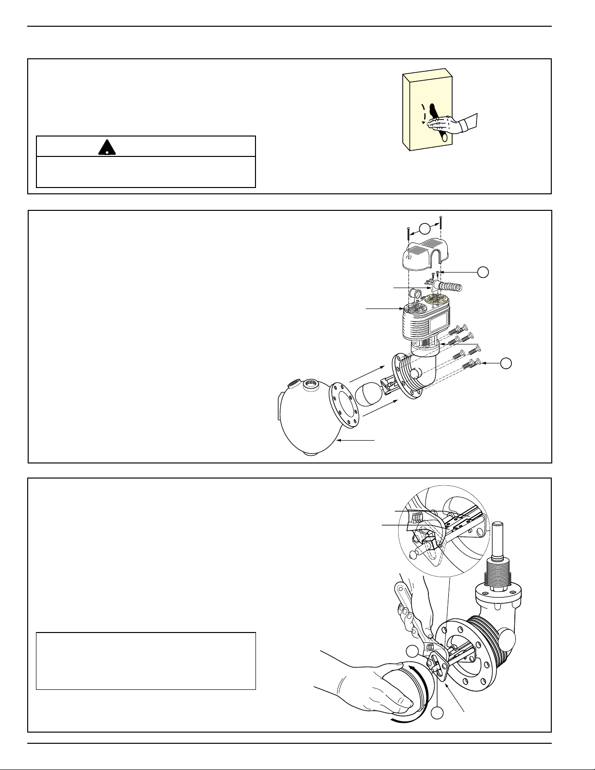
STEP 1 - Removal and Replacement Float
CONDUIT FITTING
TERMINAL PANELS
HEAD ASSEMBLY
CONTROL BODY
B
A
C
D
FLOAT ARM SPRINGS
FLOAT ARM ROD
E
!
a. Turn power off to boiler and all controls.
Allow boiler to cool to 80˚F (27˚C) and
reduce the pressure to 0 psi (0 bar).
Drain water in the boiler to a level that is
below the float chamber.
CAUTION
There may be more than one source of power to
the boiler.
b. Remove Head Assembly
• Remove two screws (A) and lift off
switch cover.
• Identify terminal connections for
rewiring and then disconnect all wires
from terminal panels.
• Remove two screws (B) and lift off
conduit fitting. Leave wires in conduit
for later reconnection.
• Remove head bolts (C). There are eight
(8) on Series 93/193 and ten (10) on
Series 94/194. Carefully remove head
assembly from control body.
• Carefully place head assembly in vice
where replacement work can be
performed
more conveniently.
ON
OFF
c. Remove and Replace Float
• Place open end of adjustable wrench on
square section of float arm (D) to keep it
from turning.
• Unscrew float ball from arm.
• Screw new float ball onto float arm rod
(E), holding square section of float arm
nut (D) with wrench and tighten securely.
IMPORTANT: Inspect condition of float
arm rod and float arm springs. If these
are damaged or bent, the entire head
assembly will need to be replaced.
2
FLOAT STOP PLATE

d. Prepare Flange Surfaces
150-14
92-68
CONDUIT FITTING
TERMINAL PANELS
HEAD ASSEMBLY
CONTROL BODY
B
A
C
Scrape and clean flange surface on
control body and control head.
IMPORTANT: Care must be taken not to
damage flange surfaces. Nicks, scrapes
or gouges may cause the flange to leak
when in service.
e. Replace Head Assembly
• Slide flange gasket (150-14 for Series
93/193 units and 92-68 for Series 94/194
units) over float ball and float stop
plate.
•
Insert head assembly by carefully guiding
float ball into control body.
• Align Gasket and install head bolts (C).
• Using a torque wrench, tighten head bolts
in an alternating star pattern. Tighten to
14-20 ft•lbs for Series 93 models. Tighten
to 17-21 ft•lbs for Series 94 models.
• Install conduit fitting with attached
wires and secure with two screws (B).
• Reconnect wiring to terminal
panels in exactly the same position
as removed.
• Replace switch cover and fasten
with two screws (A).
3

STEP 2 - Testing
!
!
– Dimensions shown are typical.
– The following testing procedure is only meant to serve as a verification of proper
operating sequence.
a. Turn on power to boiler and pump circuits.
With the boiler empty, the pump should turn on (5 or 5-M switch models) or the valve open
(7B or 7B-M switch models). The burner should remain off and boiler should begin to fill with water.
CAUTION
Immediately turn off all power if the burner turns on with no water in the gauge glass.
Investigate further before continuing procedure.
b. For Automatic Reset Models
When water level in the gauge glass is approximately 1 3/8” (35mm) above the horizontal cast line,
the burner should turn on.
For Manual Reset Models
When water level in the gauge glass is approximately 1 3/8” (35mm) above the horizontal cast line,
press the manual reset button and the burner should turn on.
c. For 5 or 5-M Switch Models
When water level in the gauge glass is approximately 2 1/8” (54mm) above the horizontal cast line,
the pump should turn off.
For 7B or 7B-M Switch Models
When water level in the gauge glass is approximately 2 11/16” (68mm) above the horizontal cast
line, the valve should be closed.
CAUTION
If pump does not turn off or valve close, turn off water supply to boiler. Investigate
further before continuing procedure.
d. With the water in the boiler at its normal level and burner on, SLOWLY open the blow-down valve
until it is fully open. As the water level in the gauge glass begins to drop, verify that the following
occurs.
For 5 or 5-M Switch Models
When water level drops to approximately 1 1/8” (29mm) above the horizontal cast line, the pump
should turn on.
When water level drops to the horizontal cast line, the burner should turn off.
For 7B or 7B-M Switch Models
As the water level drops, the valve should begin to open.
When the water level drops to approximately 7/8” (22mm) above the horizontal cast line, the valve
should be full open.
When the water level drops to the horizontal cast line, the burner should turn off.
e. Close the blow-down valve after burner turns off and restore water level to normal operating level.
f. Repeat testing procedure several times to ensure proper operation of control.
g. After testing and verification of control operation, the boiler can be returned to service.
Xylem Inc.
8200 N. Austin Avenue
Morton Grove, Illinois 60053
Phone: (847) 966-3700
Fax: (847) 965-8379
www.xyleminc.com/brands/mcdonnellmiller
McDonnell & Miller is a trademark of Xylem Inc. or one of its subsidiaries.
© 2012 Xylem Inc. MM-713B August 2012 Part No. 210421
 Loading...