

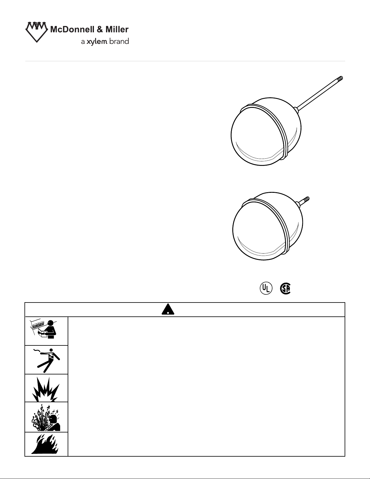
Replacement Float
!
SA63-30
For Installation on Series 63
Low Water Cut-Off
SA60-30
For Installation on Series 65/165
Liquid Level Switch
SA64-30
For Installation on Series 64/764
Low Water Cut-Off
INSTRUCTION MANUAL
MM-715B
SA63-30 Replacement Float (Weighted)
SA60-30 Replacement Float (Not Weighted)
SA64-30 Replacement Float
®
WARNING
CAUTION
ARNING
W
• Before using this product read and understand instructions.
• Save these instructions for future reference.
• All work must be performed by qualified personnel trained in the proper application,
installation, and maintenance of plumbing, steam, and electrical equipment and/or systems
in accordance with all applicable codes and ordinances.
Failure to follow this warning could cause property damage, personal injury or death.
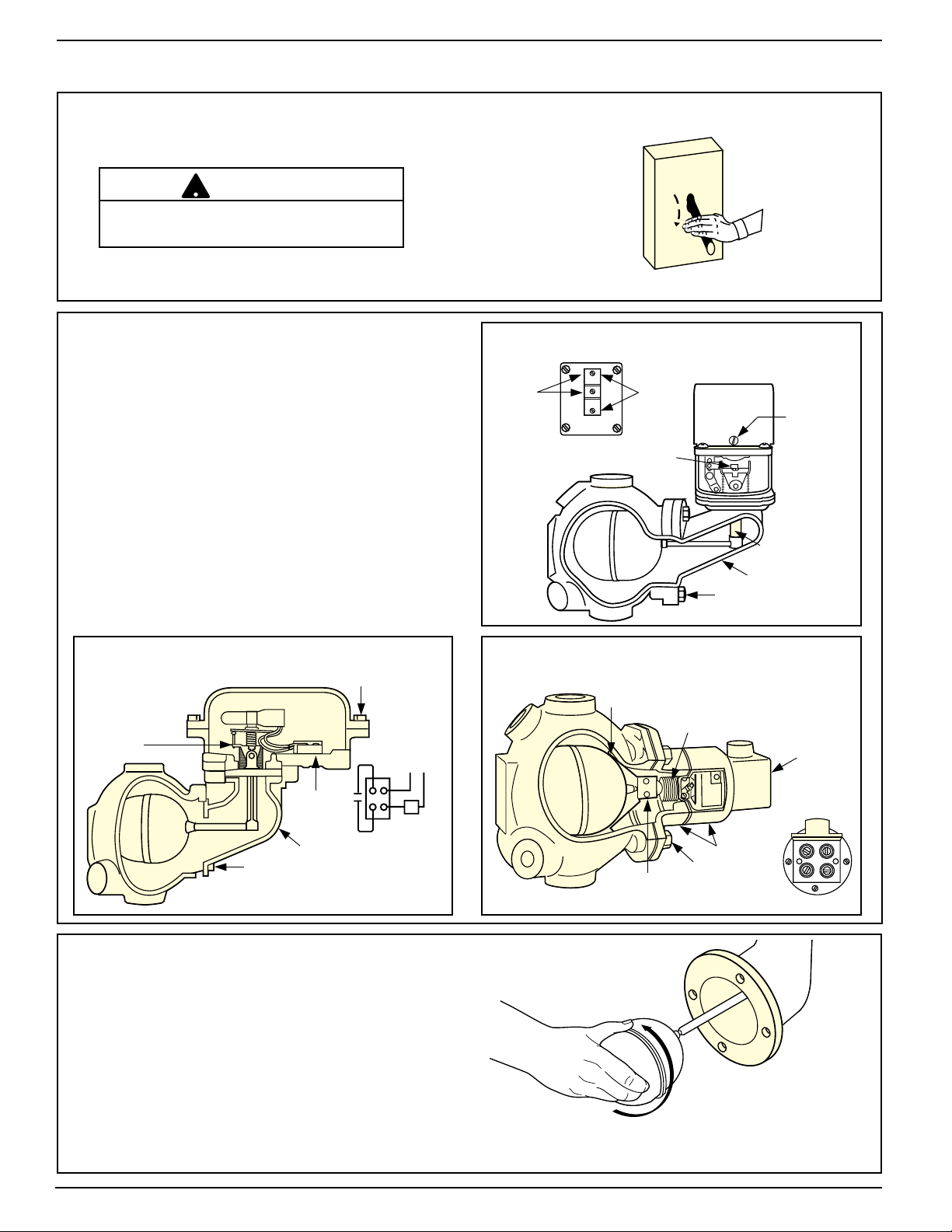
STEP 1 - Float Removal and Replacement
!
a. Turn power off to boiler and all controls.
Allow boiler to cool to 80˚F (27˚C) and
reduce the pressure to 0 psi (0 bar).
CAUTION
There may be more than one source of
power to the boiler.
Drain water in the boiler to a level that is
below the float chamber.
ON
OFF
b. Remove Head Assembly
• Remove screws (A) and lift off
switch cover.
• Identify terminal connections for
rewiring and then disconnect all wires
from terminal panels.
• Remove head bolts. Carefully remove
head assembly from control body.
• Carefully place head assembly in vice
where replacement work can be
performed
more conveniently.
MODEL 65-HD/165-HD
COVER
BOLTS (A)
SECURE THE FLOAT
ARM HERE
LINE
LOW
WATER
ALARM
TERMINALS
MODEL 63-HD
TERMINAL PANEL
C.
N.
O.
N. C.
SECURE THE
FLOAT ARM HERE
MODEL 64-HD
FLOAT STOP
BRACKET
LOW
WATER
CUT-OFF
TERMINALS
BELLOWS
FLOAT ARM
HEAD ASSEMBLY
HEX HEAD BOLTS
SWITCH COVER
SWITCH COVER
SCREW
(A)
TERMINAL
HEAD BOLTS
PANEL
HEAD ASSEMBLY
LOAD
HEX HEAD BOLTS
SECURE
FLOAT MOUNTING BLOCK
HERE
HEAD ASSEMBLY
TERMINAL PANEL
TOP
1
2
34
c. Remove and Replace Float
• While securely holding the arm or mounting
block, where indicated in the diagram
above, unscrew float ball from the assembly
Holding the arm or mounting block reduces
the risk of damaging the bellows from
unnatural stresses.
• Screw new float onto assembly.
On model 64 units, be sure the float stop
bracket is in proper position.
2

d. Prepare Flange Surfaces
Scrape and clean flange surface on
control body and control head.
IMPORTANT: Care must be taken not to
damage flange surfaces. Nicks, scrapes
or gouges may cause the flange to leak
when in service.
e. Replace Head Assembly
• Slide flange gasket over float ball.
•
Insert head assembly by carefully guiding
float ball into control body.
• Align Gasket and install head bolts.
• Using a torque wrench, tighten head bolts
in an alternating star pattern. Tighten to
14-20 ft•lbs.
• Reconnect wiring to terminal
panels in exactly the same position
as removed.
• Replace switch cover and fasten
with screws. On Model #65, cover and
housing surfaces must be free of grit and
debris for proper seal. On Model #165,
replace the cover gasket.
MODEL
63-HD
MODEL
64-HD
MODEL
65-HD/165-HD
3

STEP 2 - Testing the Control
a. Turn the boiler on.
b. Fill the control and check for gasket leakage.
c. Slowly open the blow-down valve which will
lower the water level in the float chamber.
When the water level drops to the horizontal
cast line, the burner should turn off. Close the
blow- down valve after the burner turns off
and restore the water level to normal operating
level. Repeat testing procedure several times to
ensure proper operation of control.
After testing and verification of control operation,
the boiler can be returned to service.
MAINTENANCE
SCHEDULE:
• Blow down control as follows when boiler is in
operation.
• Steam:
— Daily if operating pressure is above 15 psi.
— Weekly if operating pressure is below 15 psi.
• Hot Water:
— Quarterly
NOTE
More frequent blow-down may be necessary due to
dirty water and/or local codes.
• Disassemble and inspect annually. Replace the
low water cut-off if it is worn, corroded, or if
components no longer operate properly.
• Inspect the float chamber and equalizing piping
annually. Remove all sediment and debris.
• Replace head mechanism every 5 years.
More frequent replacement may be required
when severe conditions exist such as rapid switch
cycling, surging water levels, and use of water
treatment chemicals.
• We recommend head mechanism replacement
when the switch(es) no longer operate properly.
If you choose to replace the switch(es), order the
proper McDonnell & Miller replacement switch or
switch assembly and follow the repair procedure
provided.
CAUTION
Immediately turn off all power if the burner turns on with
no water in the gauge glass. Investigate further before
continuing procedure.
!
ON
OFF
PROCEDURE:
CAUTION
!
To prevent serious personal injury from
steam pipe blow down, connect a drain
pipe to the control opening to avoid
exposure to steam discharge.
Failure to follow this caution could cause
personal injury.
Blow down the low water cut-off when the water
level is at the normal level and the burner is on.
Slowly open the blow down valve until it is fully
open and observe the water level fall in the gauge
glass. Close the valve after verifying that the pump
contacts have closed and the burner shuts off. If this
does not happen, immediately shut off the boiler
and correct the problem.
Xylem Inc.
8200 N. Austin Avenue
Morton Grove, Illinois 60053
Phone: (847) 966-3700
Fax: (847) 965-8379
www.xyleminc.com/brands/mcdonnellmiller
McDonnell & Miller is a trademark of Xylem Inc. or one of its subsidiaries.
© 2012 Xylem Inc. MM-715B August 2012 Part No. 246001
 Loading...