

Page 1
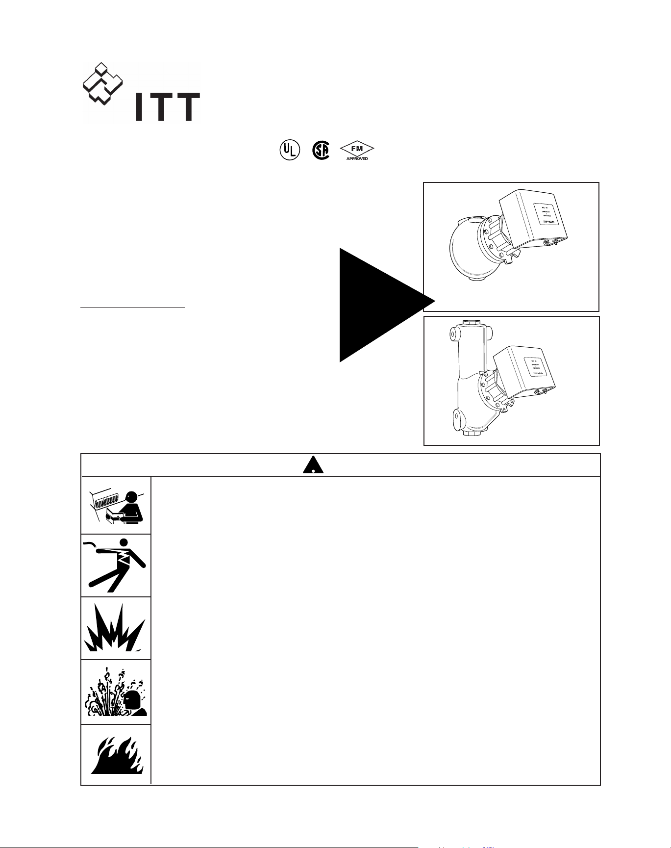
Series 150E and 157E
Low Water Cut-Off/Pump Controllers
For Steam Boilers and Other Level Control Applications
Typical Applications:
– Primary or secondary pump controller/
low water fuel cut-off
for steam boilers
– Motorized valve controller
– Low water and high water cut-off
– Dual pump control
– Alarm actuator
A
B
• Before using this product read and understand instructions.
•Save these instructions for future reference.
• All work must be performed by qualified personnel trained in the proper application, installation, and maintenance of plumbing, steam, and electrical equipment and/or systems in
accordance with all applicable codes and ordinances.
•To prevent serious burns, the boiler must be cooled to 80˚F (27˚C) and the pressure must be
0 psi (0 bar) before servicing.
•To prevent electrical shock, turn off the electrical power before making electrical connections.
• This low water cut-off must be installed in series with all other limit and operating controls
installed on the boiler. After installation, check for proper operation of all of the limit and
operating controls, before leaving the site.
•We recommend that secondary (redundant) low water cut-off controls be installed on all
steam boilers with heat input greater than 400,000 BTU/hour or operating above 15 psi of
steam pressure. At least two controls should be connected in series with the burner control
circuit to provide safety redundancy protection should the boiler experience a low-water
condition. Moreover, at each annual outage, the low water cut-offs should be dismantled,
inspected, cleaned, and checked for proper calibration and performance.
•To prevent serious personal injury from steam blow down, connect a drain pipe to the control
opening to avoid exposure to steam discharge.
•To prevent a fire, do not use this low water cut-off to switch currents over 16A, 1 Hp at
120 VAC or 8A, 1 Hp at 240 VAC, unless a starter or relay is used in conjunction with it.
Failure to follow this warning could cause property damage, personal injury or death.
WARNING
CAUTION
!
WARNING
Series 150E
Series 157E
®
with
MERCURY
FREE
1 HP
Relays
U.S. Pat. No. 6,571,625
McDonnell & Miller
Installation & Maintenance
Instructions
MM-414(B)
Page 2
SPECIFICATIONS
Maximum Pressure: 150 psi (10.5 kg/cm2)
2
FEATURES
Burner Delay (DOB): 0 to 60 seconds (Field Adjustable)
Ambient Temp: 120˚F Max.
NOTE: The circuit board is protected with a sensor which will
shut down the unit if the temperature at the board exceeds
176˚F (80˚C). The board will reset when the temperature at
the board drops below 167˚F (75˚C).
Burner Relay Time Delay
There is a field-adjustable time delay (DOB) to
prevent nuisance burner shut-down. The number
of seconds water needs to be off the bottom probe
before the burner relay is deactivated can be set
between 0 and 60 seconds.
Redundant Low Water Cut-Off
When the boiler water drops below the middle
probe, a 3 minute timing circuit will be activated. If
water does not return to the middle probe within
three minutes, the burner relay will deactivate. The
Red LED will flash once every second if this
condition occurs.
•Automatic Reset units will automatically reset
when the water level is restored to the middle
probe.
• The reset button on Manual Reset units will
have to be pressed after water is restored to
the middle probe.
NOTE: The timing circuit will automatically reset
if the water level is restored to the middle probe
within 3 minutes.
Redundant Pump Off
The pump relay will be activated after water drops
below the middle probe. If the water level is not
restored to the top probe within 3 minutes the pump
relay will be deactivated. After the pump relay is
deactivated, normal operation is resumed. Water
must again drop off the middle probe to activate the
pump relay. There is no LED signal for this
occurance.
CSD-1 Code Compliance
On Manual Reset units, if the control is in a low
water condition (burner relay deactivated) prior to
an interruption of power, the control will remain in a
low water condition when power is restored. The
reset button will need to be pressed when the water
level again covers the middle probe.
Adjustable Pump Differentials
ELECTRICAL RATINGS & SWITCH RATINGS
Supply Probe Full Load (Amps) Locked Rotor (Amps) Pilot Duty (VA) Motor (HP)
Voltage Voltage NO (NC), VAC NO (NC), VAC NO (NC), VAC NO (NC), VAC
120 VAC 5 VAC 16 (5.8), 120 96 (34.8), 120 470 (290), 120 1 (1/4), 120
50/60 HZ maximum 8 (2.9), 240 48 (17.4), 240 470 (290), 240 1 (1/4), 240
Page 3
3
BURNER
CUT-OFF LEVEL
AT CAST LINE
(22mm)
BURNER OFF
BURNER ON
7
/8"
PUMP
OFF
BURNER
OFF
BURNER
CUT-OFF LEVEL
AT CAST LINE
2
1
/16"
(52 mm)
NORMAL BOILER
WATER LINE
1
3
/16"
(30 mm)
PUMP OFF
PUMP ON
NORMAL BOILER
WATER LINE
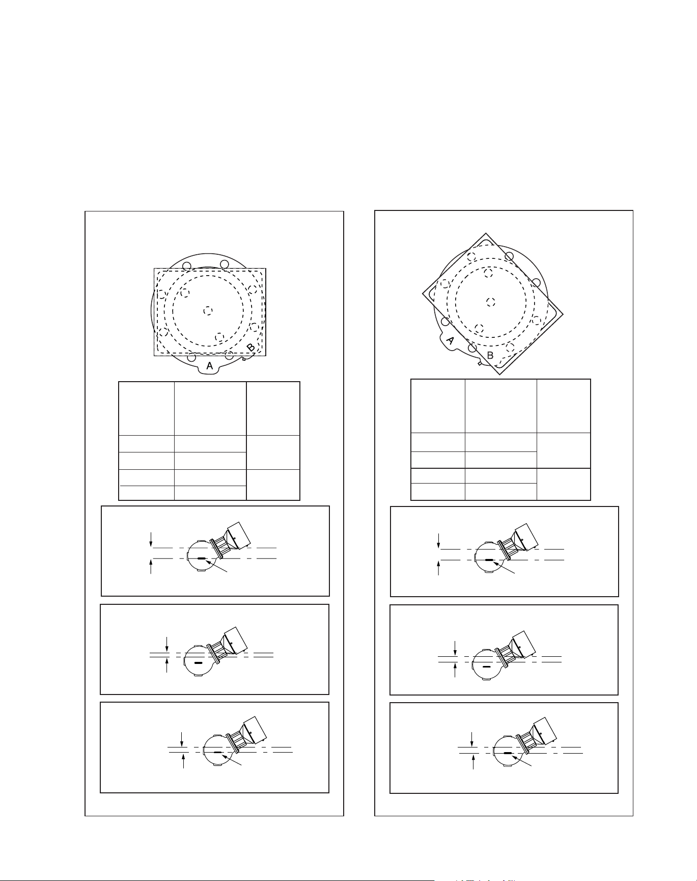
When the water level in the boiler drops below the
middle probe, the circuit is broken which will activate the pump relay. When the water level rises
above the top probe, the circuit is made and the
pump relay is deactivated.
The distance between the top and middle probes is
adjustable. By turning the flange one bolt hole
clockwise, the distance can be increased by 7/16”.
When the water level in the boiler drops below the
bottom probe, the circuit is broken which will deactivate the burner relay. When the water level is
restored to the middle probe, the burner relay will
be activated for auto reset controls only.
SWITCH SETTINGS:
Values are ±
3
/16” (6mm).
Flange in “B” PositionFlange in “A” Position
Burner Off has adjustable 0-60 second time delay.
Approximate
Distance Above
Cast Line Differential
Setting In. (mm) In. (mm)
Pump Off 1
5
/8 (41)
3
/4 (19)
Pump On
7
/8 (22)
Burner On
7
/8 (22)
7
/8 (22)
Burner Off 0 (0)
BURNER
CUT-OFF LEVEL
AT CAST LINE
(22mm)
BURNER OFF
BURNER ON
7
/8"
PUMP
OFF
BURNER
OFF
BURNER
CUT-OFF LEVEL
AT CAST LINE
1
5
/8"
(41mm)
NORMAL BOILER
WATER LINE
3
/4" (19 mm)
PUMP OFF
PUMP ON
NORMAL BOILER
WATER LINE
Burner Off has adjustable 0-60 second time delay.
Approximate
Distance Above
Cast Line Differential
Setting In. (mm) In. (mm)
Pump Off 2
1
/16 (52)
13/16(30)
Pump On
7
/8 (22)
Burner On
7
/8 (22)
7
/8(22)
Burner Off 0 (0)
Page 4
4
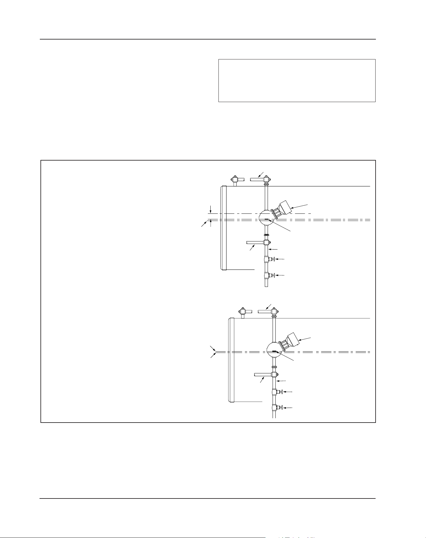
If the control will be the primary low
water fuel cut-off, size the steam (top)
and water (bottom) equalizing pipe lengths
so that the horizontal cast line on the body
is 1
3
/8” (35mm) below the boiler’s normal
water level, but not lower than the
lowest safe permissible water level, as
determined by the boiler manufacturer.
OR
If the control will be the secondary low
water fuel cut-off, size the steam (top) and
water (bottom) equalizing pipe lengths so
that the horizontal cast line on the body is
at or above, the lowest safe permissible
water level, as determined by the boiler
manufacturer.
STEP 1 - Determine the Elevation at Which the
Low Water Cut-Off/Pump Controller Must be Installed
INSTALLATION –
TOOLS NEEDED:
Tw o (2) pipe wrenches, one (1) flatblade screwdriver, and pipe sealing compound.
IMPORTANT: Follow the boiler manufacturer's
instructions along with all applicable codes and
ordinances for piping, blow down valve and water
gauge glass requirements.
13/8"
STEAM EQUALIZING PIPE
VERTICAL EQUALIZING PIPE
NORMAL BOILER WATER LINE
AS A PRIMARY
LOW WATER CUT-OFF/PUMP
CONTROLLER
BURNER CUT-OFF LEVEL AT CAST LINE
LOWEST
PERMISSIBLE
WATER LEVEL
(35mm)
WATER
EQUALIZING
PIPE
BLOW DOWN VALVE
BLOW DOWN VALVE
STEAM EQUALIZING PIPE
VERTICAL EQUALIZING PIPE
BLOW DOWN VALVE
BURNER CUT-OFF LEVEL AT CAST LINE
LOWEST
PERMISSIBLE
WATER LEVEL
BURNER OFF
WATER
EQUALIZING
PIPE
AS A SECONDARY
LOW WATER CUT-OFF/PUMP
CONTROLLER
BLOW DOWN VALVE
Page 5
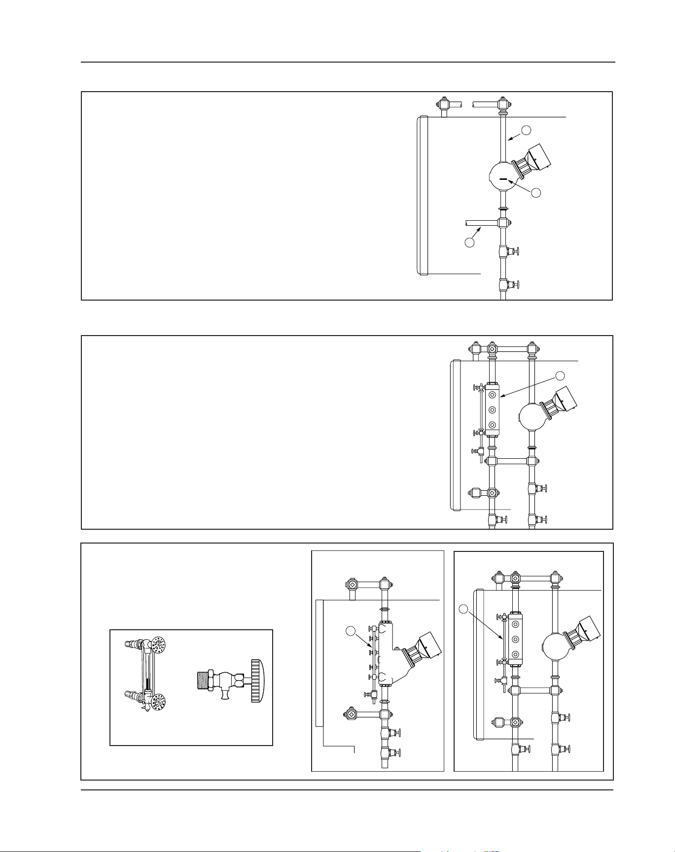
b. Install a water gauge glass (J).
Note: Gauge glass and tri-cocks
not included with product.
J
5
F
E
D
a. Mount and pipe the low water cut-off (D) on a
vertical equalizing pipe (E) at the required elevation level, as determined in Step 1.
Install blow down valves directly below the
lower cross of the water equalizing pipe (F).
STEP 2 - Installing the Low Water Cut-Off
J
H
a. Install a water column (H) (not included with
product) for all models except Series 157E,
(with integral water column).
STEP 3 - Installing a Water Gauge Glass (Required on all steam boilers)
Series 157E
All Other Models
GAUGE GLASS
(TYPICAL)
TRI-COCK
(TYPICAL)
Page 6

6
Cover
A
Loosen screws (A) and remove cover.
BCOM
BNC
BNO
PCOM
PNC
PNO
N
H
BCOM
BNC
BNO
PCOM
PNC
PNO
N
H
60
30
Secs.
0
60
30
Secs.
0
B
Probe Wires
B
Control Box
B
B
• Disconnect probe wires (red, blue, yellow) from
circuit board.
• Remove 4 screws (B) connecting control box to
brackets, lifting control box from brackets.
Remote Mounting of the Control Box
Page 7

Probes
Disconnect wires from probes.
Cover Plate
Brackets
C
C
C
C
C
C
Offset Connector
• Remove 6 screws (C) connecting brackets
and cover plate to probe housing.
• Remove offset connector from cover plate.
7
Only loosen upper nut to remove probe wire.
NOTE
Upper Nut
Page 8

8
• Mount Control Box in a suitable location near
the boiler’s main electrical panel.
• Install electrical conduit between Probe
Housing and Control Box.
• Pull four (4) wires through conduit.
Boiler sight glass must be visible from location of
Control Box and must be within 25 feet of Control
Box.
NOTE
Refer to and follow local codes and standards
when selecting conduit and electrical fittings.
Wires from Probe Housing to Control Box must be
in their own conduit. If they are run in conduit with
other wires, there may be interference that can
affect the performance of the control.
NOTE
Wire must be 18 AWG stranded with glass braided
silicone jacket (UL 3071) suitable for high temperature (200˚C) service.
NOTE
Page 9

9
Screws
Plate Ground
Blue/Top
Yellow/Middle
Red/Bottom
Connect wires between Control Box and Probes
as follows.
Pr
obes Control
Top/Blue Top/Blue
Middle/Yellow Middle/Yellow
Bottom/Red Bottom/Red
Plate Ground Chassis Ground
• Attach cover plate to probe housing.
• Use knockout plug from probe housing to plug
the hole in the cover plate.
• Proceed to Electrical Wiring Section to complete
wiring to Burner and Pump/Valve circuits.
Wire connections at Probes (1/4” Ring Terminal) and
Control Panel (22-18 Female Spade) must be made
with connectors suitable for high temperature (200˚C)
service.
NOTE
BCOM
BNC
BNO
PCOM
PNC
PNO
N
H
BCOM
BNC
BNO
PCOM
PNC
PNO
N
H
60
30
Secs.
0
60
30
Secs.
0
BCOM
BNC
BNO
PCOM
PNC
PNO
N
H
BCOM
BNC
BNO
PCOM
PNC
PNO
N
H
60
30
Secs.
0
60
30
Secs.
0
Probe wires
Control Box
Chassis Ground
Page 10

10
STEP 4 - Electrical Wiring
•To prevent electrical shock, turn off the electrical power before making electrical connections.
• This low water cut-off must be installed in series with all other limit and operating controls installed on the
boiler. After installation, check for proper operation of all of the limit and operating controls, before leaving
the site.
• Boiler manufacturer schematics should always be followed. In the event that the boiler manufacturer’s
schematic does not exist, or is not available from the boiler manufacturer, refer to the schematics provided
in this document.
Failure to follow this warning could cause electrical shock, an explosion and/or a fire, which could result in
property damage, personal injury or death.
!
WARNING
L
Cover Removal and Installation Procedure
a. To remove cover, use a flatblade screwdriver to
loosen screws and remove the cover (K).
b. To reconnect cover, slide over brackets and tighten
screws using a flatblade screwdriver.
c. Following the appropriate wiring diagram (refer to
page 11) based on your application requirements,
and using BX armored cable or Thinwall electrical
metal tubing connector fittings, make electrical
connections to the junction box (L).
IMPORTANT: There must be a minimum space
of 2” (13mm) between connector fittings and
electrical live metal parts.
Circuit Board Layout
BCOM
BNC
BNO
PCOM
PNC
PNO
N
H
BCOM
BNC
BNO
PCOM
PNC
PNO
N
H
60
30
Secs.
0
60
30
Secs.
0
BCOM
BNC
BNO
PCOM
PNC
PNO
N
H
0 60
30
Secs.
0
Probe Connections
Bottom
Red
Middle
Yellow
To p
Blue
0-60 Second Adjustable
Burner Off Delay
110 Volt Input
from Boiler
Circuit
Manual Reset
(If applicable)
Low Water
LED
Red
Powe r
LED
Green
Test
Switch
Burner
Te r minals
Pump
Te r minals
BCOM
BNC
BNO
PCOM
PNC
PNO
N
H
Probe LED's
K
Page 11

11
PUMP
OPERATION
BURNER
OPERATION
FROM BURNER OR ALARM
CONTROL CIRCUIT
TO ALARM
CONTROL CIRCUIT
TO BURNER
CONTROL CIRCUIT
FROM PUMP UP
CONTROL CIRCUIT
TO PUMP UP
CONTROL CIRCUIT
NEUTRAL
HOT
BCOM
BNC
BNO
PCOM
PNC
PNO
N
H
g
f
e
d
c
b
a
• Connect wire “a” from power supply to terminal “H”.
• Connect wire “b” from neutral supply to terminal “N”.
• Connect wire “c” from pump control circuit to terminal “PNO”.
• Connect wire “d” from pump control circuit to terminal “PCOM”.
• Connect wire “e” from burner control circuit to terminal “BNO”.
• Connect wire “f” from alarm control circuit to terminal “BNC”.
• Connect wire “g” from burner or alarm control circuit to
terminal “BCOM”.
WIRING DIAGRAMS
Low Water Cut-Off, Alarm and Pump Up Control
PUMP 1
OPERATION
PUMP 2
OPERATION
FROM PUMP #1
CONTROL CIRCUIT
FROM PUMP #2
CONTROL CIRCUIT
TO PUMP #2
CONTROL CIRCUIT
TO PUMP #1
CONTROL CIRCUIT
NEUTRAL
HOT
BCOM
BNC
BNO
PCOM
PNC
PNO
N
H
f
e
d
c
b
a
• Connect wire “a” from power supply to terminal “H”.
• Connect wire “b” from neutral supply to terminal “N”.
• Connect wire “c” from pump #1 control circuit to terminal “PNO”.
• Connect wire “d” from pump #1 control circuit to terminal “PCOM”.
• Connect wire “e” from pump #2 control circuit to terminal “BNC”.
• Connect wire “f” from pump #2 control circuit to terminal “BCOM”.
Dual Pump Control
VALV E
SPRING
CLOSED
BURNER
OPERATION
VALV E
DRIVE
TO OPEN
• Connect wire “a” from power supply to terminal “H”.
• Connect wire “b” from neutral supply to terminal “N”.
• Connect wire “c” from valve control circuit to terminal “PNO”.
• Connect wire “d” from valve control circuit to terminal “PCOM”
• Connect wire “e” from burner
control circuit to terminal “BNO”.
• Connect wire “f” from alarm
control circuit to terminal “BNC”.
• Connect wire “g” from burner
or alarm control circuit to
terminal “BCOM”.
Motorized Valve and Low Water Cut-Off
FROM VALVE
CONTROL CIRCUIT
TO VALVE
CONTROL CIRCUIT
NEUTRAL
HOT
BCOM
BNC
BNO
PCOM
PNC
PNO
N
H
d
c
b
a
FROM BURNER OR ALARM
CONTROL CIRCUIT
TO ALARM
CONTROL CIRCUIT
TO BURNER
CONTROL CIRCUIT
g
f
e
Page 12

12
STEP 5 - Testing
Procedure
OFF
ON
Tu rn on power to the boiler and pump circuits. With the boiler empty, the
control will be activated (Green LED On) and the pump should turn on.
The burner should stay off (Red LED On).
NOTE: If Green and Red LED’s flash alternately, the probes are not connected in sequence. Turn off power and check probe wires for proper
connection.
• Green light on: Unit has power
• Red light on: Boiler water dropped below the bottom probe for longer than the adjustable time delay
setting. The burner has shut down.
• Red light flashing every second: Boiler water was below the middle probe for more than three
minutes and the burner has shut down.
• Auto reset units will automatically reset when the boiler water returns to the middle probe.
• Manual reset units must be manually reset after boiler water returns to the middle probe.
• Red light and green light flashing alternately every 1/2 second. Probes are out of sequence.
Unit has shut down. Unit will automatically reset when condition has cleared or been corrected.
• Red light and green light flashing simultaneously every 1/2 second: The PCB is too hot and the unit
has shut down. The unit will automatically restart when the PCB has cooled sufficiently.
• When using the “TEST” button, the green light will flash once per second during the time delay interval.
The time delay setting can be determined by counting the number of flashes.
Green Light – Shows status of top probe
Yellow Light – Shows status of middle probe
Red Light – Shows status of bottom probe
• If the light is on, the probe is in water and probe resistance is well below the threshold.
• If the light is flashing every 1/2 second, the probe is in water, but probe resistance is near (just below)
the threshold.
• If the light is flashing every 2 seconds, the probe is out of water, but probe resistance is near (just above)
the threshold.
• If the light is off, the probe is out of water and probe resistance is well above the threshold.
IMPORTANT: Follow the boiler manufacturer’s start-up and operating instructions along with all applicable
codes and ordinances.
If the burner comes on, immediately turn the boiler off and make the
necessary corrections.
Failure to follow this warning could cause an explosion or fire and
result in property damage, personal injury or death.
!
WARNING
Exterior Lights
Interior Lights
Page 13

13
Adjusting Burner Delay (DOB)
The boiler should begin to fill with water.
NOTE: If water does not start filling the boiler,
immediately turn off the the boiler and make
the necessary corrections.
For Automatic Reset Models:
When the water level reaches the level of the
middle probe, the burner circuit should be activated and the Red LED should turn off. (Pump
#2 should turn off with Dual Pump Applications).
For Manual Reset Models:
The reset button must be pushed to activate the
burner circuit when water reaches the level of the
middle probe.
When the water level rises to the level of the top
probe, the pump relay will be de-activated.
Depending on the application, this will either turn
off the pump or close a valve.
BCOM
BNC
BNO
PCOM
PNC
PNO
N
H
BCOM
BNC
BNO
PCOM
PNC
PNO
N
H
60
30
Secs.
0
60
30
Secs.
0
BCOM
BNC
BNO
PCOM
PNC
PNO
N
H
0 60
30
Secs.
0
Probe Connections
Bottom
Red
Middle
Yellow
Top
Blue
0-60 Second Adjustable
Burner Off Delay
110 Volt Input
from Boiler
Circuit
Manual Reset
(If applicable)
Low Water
LED
Red
Powe r
LED
Green
Test
Switch
Burner
Te r minals
Pump
Te r minals
BCOM
BNC
BNO
PCOM
PNC
PNO
N
H
Probe LED's
The number of seconds that water must be off the
bottom probe before the burner will turn off is
adjustable from 0 to 60 seconds with the unit factory
set at 0 seconds. To adjust, turn the adjusting screw
clockwise using a small flatblade screwdriver to the
delay time desired.
Follow the blow down procedure found on page 15
to verify operation.
INSTALLATION COMPLETE
If the delay time is too long, the manual reset secondary LWCO may turn off the boiler before this control turns off the boiler. If this occurs, shorten the time
delay by turning the adjustment screw counter-clockwise from the new setting.
NOTE
Page 14

14
Troubleshooting
Green LED does not turn on.
• There may be no power to the unit. Check wiring
connected to ‘H’ and ‘N’ terminals on circuit board.
Verify that the control is being powered when the
boiler power is turned on.
Red & Green LEDs flash alternately every
1/2 second.
• The probes are out of sequence. Check probe
wires and connections.
• The control head flange is not installed properly.
“A” or “B” tabs must be installed at bottom of body.
Red & Green LEDs flash simultaneously every 1/2
second.
• The temperature at the circuit board is higher than
170˚F. Removing the control box cover may cool
the control enough for it to operate. If the control
works with the cover removed, the control box
should then be mounted remotely.
Pump does not turn off when water level is above
top probe.
• The probes may be fouled with dirt, scale or rust.
Remove head assembly to inspect probes.
•The wiring connections for the pump may not be
connected properly. Check wiring at terminals.
Pump does not turn on when water level is below
the middle probe.
• The probes may be fouled with dirt, scale or rust.
Remove head assembly to inspect probes.
•The wiring connections for the pump may not be
connected properly. Check wiring at terminals.
Burner does not turn off when water level is
below bottom probe.
• The probes may be fouled with dirt, scale or rust.
Remove head assembly to inspect probes.
•The wiring connections for the pump may not be
connected properly. Check wiring at terminals.
• Make sure time delay is not causing delay of
burner off.
The 150E control does not turn off the burner
before the secondary (manual reset LWCO) turns
off the burner.
•The burner off time delay (DOB) may be set for too
long of a delay.
During operation, the burner does not turn off
when the water level is below the bottom probe.
•The burner off time delay (DOB) may be set for too
long of a delay.
• The boiler water may be priming or foaming. Clean
boiler water and/or consult with chemical treatment
specialist.
During operation, the burner turns off even when
the pump has turned on or the motorized valve
has opened.
• Pump capacity may not be sufficient or there may
be restrictions in the feedwater piping. Check pump
capacity and piping.
• The motorized valve stroke-to-open time may be
too long. Check valve motor timing.
Page 15

15
Valve #1
Valve #2
BLOW DOWN PROCEDURE:
When blowing down a control at pressure, the blow
down valves should be opened slowly. The piping needs
to be warmed up and stagant water in the drain piping
needs to be pushed out. Suddenly opening a blow down
valve causes steam to condensate, which creates water
hammer. Damage to components can occur when water
hammer occurs due to improper blow down piping.
For these reasons, McDonnell & Miller recommends a
dual valve blow-down system for each control.
Blow down the low water cut-off when the water level is
at its normal level (pump/valve off) and the burner is on.
• Open the upper “Positive Shut-off Ball Valve” (#1).
• Slowly open lower “Throttling Gate Valve” (#2).
• With both valves open, the water level will drop in
the sight glass.
• When the water falls below the level of the middle
probe, the pump or valve should turn ON.
• When the water falls below the level of the bottom
probe, the burner should turn OFF. NOTE: The
Red LED will turn ON to indicate low water condition.
• Slowly close the lower “Throttling Gate Valve” (#2).
• The water level should begin to rise and the burner
should turn ON (Red LED turns off) when the level
is at the middle probe. The pump or valve should
turn OFF when the water level rises above the top
probe postion.
NOTE: On manual reset models, the red reset button will
need to be pressed after the water level is restored to the
level of the middle probe before the burner will operate.
• Close the upper valve “Positive Shut-off Ball Valve” (#1).
• Observe that the water level returns to its normal level
before leaving the site.
To prevent serious personal injury from steam
pipe blow down, connect a drain pipe to the
control opening to avoid exposure to steam
discharge.
Failure to follow this caution could cause
personal injury.
!
CAUTION
MAINTENANCE
SCHEDULE:
Blow down control as follows when boiler is in
operation.
• Daily if operating pressure is above 15 psi.
•Weekly if operating pressure is below 15 psi.
Disassemble and inspect annually.
•
Inspect the float/probe chamber and equalizing
piping annually.
Remove all sediment and
debris from chamber and/or equalizing piping.
• Inspect and clean probes. Use a non-abrasive
cloth to clean probes and water-side of
probe-mounting flange. Replace head mechanism
and probes if probes are worn, corroded or have
excessive coating of scale or rust that cannot be
easily cleaned off.
Replace head mechanism every 5 years.
More frequent replacement may be required when
severe conditions exist.
Replacement parts are available from your
local authorized McDonnell & Miller
Distributor. The use of parts or components other
than those manufactured by McDonnell & Miller
will void all warranties and may affect the units'
compliance with listings or regulating agencies.
WARNING
DO NOT REMOVE PROBES FROM FLANGE. Replace probe
flange assembly if probe Teflon
®
insulation is broken, torn
or frayed.
NOTE
The probes may need to be inspected and cleaned more
frequently on systems where there is the potential of
coating build-up on the probes.This includes systems:
• With high raw water make-up
• With no condensate return
• With untreated boiler water
• Where significant changes have been made to the
boiler-water chemical treatment process
• With oil in the boiler water
NOTE
More frequent blow-down may be necessary due to
dirty boiler water and/or local codes.
NOTE
If this sequence of actions does not occur, as
described, immediately close all valves, turn off the
boiler and correct the problem. To correct the problem,
inspection/cleaning of all probes may be required.
Page 16

ITT
8200 N. Austin Ave.
Morton Grove, IL 60053
tel: 847-966-3700
fax: 847-966-9052
www.mcdonnellmiller.com
McDonnell & Miller
©2007 ITT Corporation
Printed in U.S.A. 5-07 210496
 Loading...