

Page 1
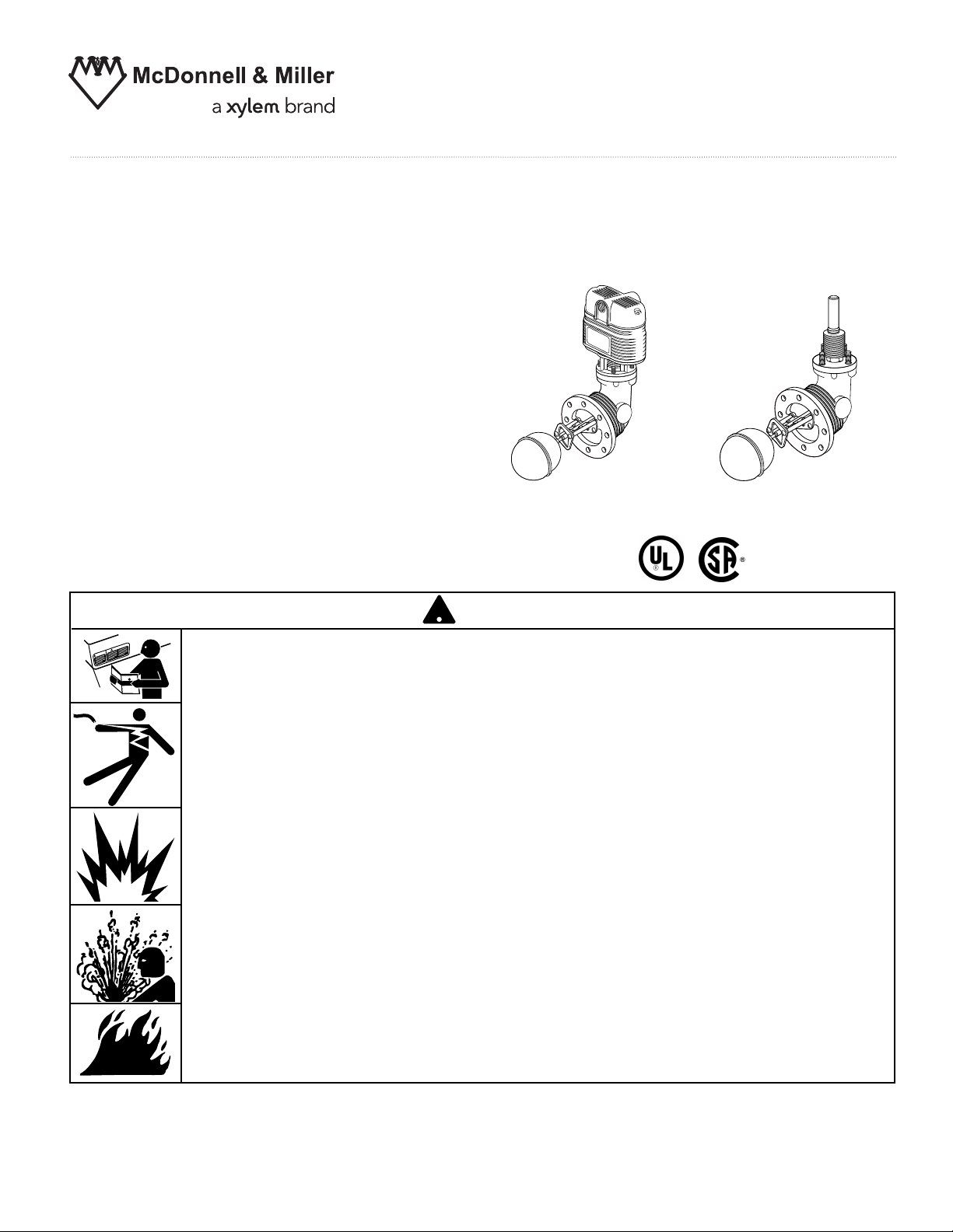
Replacement Head Mechanism
!
With Switch Assembly:
93-HD, 94-HD
93-M-HD, 94-M-HD
93-7B-HD, 94-7B-HD
93-7B-M-HD, 94-7B-M-HD
Without Switch Assembly:
93-HDLS 94-HDLS
Replacement head mechanisms can be
installed without disturbing existing equalizing
connections or disassembly of components,
making repair simple and easy.
Head Mechanism
with Switch Assembly
INSTRUCTION MANUAL
MM-413F
Head Mechanism
without Switch Assembly
WARNING
N
UTIO
CA
G
IN
RN
A
W
• Before using this product read and understand instructions.
• Save these instructions for future reference.
• All work must be performed by qualified personnel trained in the proper application, installation, and maintenance of plumbing, steam, and electrical equipment and/or systems in
accordance with all applicable codes and ordinances.
• To prevent serious burns, the boiler must be cooled to 80˚F (27˚C) and the pressure must be
0 psi (0 bar) before servicing.
• To prevent electrical shock, turn off the electrical power before making electrical connections.
• This low water cut-off must be installed in series with all other limit and operating controls
installed on the boiler. After installation, check for proper operation of all of the limit and
operating controls, before leaving the site.
• We recommend that secondary (redundant) Low Water Cut-Off controls be installed on all
steam boilers with heat input greater than 400,000 BTU/hour or operating above 15 psi
steam pressure. At least two controls should be connected in series with the burner
control circuit to provide safety redundancy protection should the boiler experience a
low-water condition. Moreover, at each annual outage, the low water cutoffs should be
dismantled, inspected, cleaned, and checked for proper calibration and performance.
• To prevent serious personal injury from steam blow down, connect a drain pipe to the control
opening to avoid exposure to steam discharge.
• To prevent a fire, do not exceed the switch contact rating.
Failure to follow this warning could cause property damage, personal injury or death.
Page 2
2
Electrical Ratings
Models with 5 or 5-M Switch
Switch Ratings
Burner Valve
120 VAC
345 VA 0 - 135 ohms @ 24 VAC
240 VAC
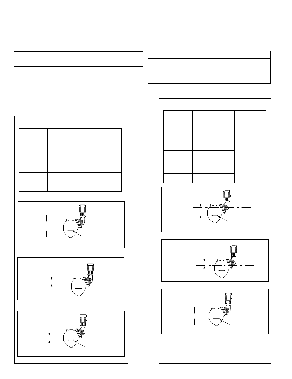
Models with 7B or 7B-M Switch
Approximate
Distance Above
Cast Line Differential
Setting In. (mm) In. (mm)
Pump Off 23/16 (56) 11/16 (27)
Pump On 11/8 (29)
Burner On 13/8 (35) 13/8 (35)
Burner Off 0
Switch Settings
Values are ±
1
/8 " (3mm)
NOTE: Due to the slower operation of some
motorized valves, complete valve opening or
closing may occur at slightly different
levels than indicated above.
Models with 5 or 5-M Switches
Approximate
Distance Above
Cast Line Differential
Setting In. (mm) In. (mm)
Valve Full 23/16 (56) 11/16 (27)
Closed
Valve Full
7
/8 (22)
Open
Burner On 13/8 (35) 13/8 (35)
Burner Off 0
Models with 7B or 7B-M Switches
OPERATION
Maximum Pressure:
Series 93/193: 150 psi (10.5 kg/cm
2
)
Series 94/194: 250 psi (17.6kg/cm
2
)
PUMP
OFF
BURNER
OFF
BURNER
CUT-OFF LEVEL
AT CAST LINE
2
3
/16"
(56mm)
PUMP OFF
PUMP ON
(27mm)
1
1
/16"
BURNER
“CUT-OFF LEVEL”
AT CAST LINE
BURNER OFF
(35mm)
BURNER ON
1
3
/8"
BURNER
“CUT-OFF LEVEL”
AT CAST LINE
BURNER OFF
(35mm)
BURNER ON
1
3
/8"
MOTORIZED
VALV E
CLOSED
BURNER
OFF
BURNER
CUT-OFF LEVEL
AT CAST LINE
2
3
/16"
(56mm)
MOTORIZED
VALV E
CLOSED
MOTORIZED
VALV E
OPEN
(27mm)
1
1
/16"
Pump and Burner Switch Contact Ratings
Voltage Pilot Duty Only
120 VAC
345 VA
240 VAC
Page 3

3
OFF
ON
STEP 1 - Preparation
INSTALLATION –
TOOLS NEEDED:
One (1) flathead screw driver, one (1) scraper and
one (1) 9/16" socket box or open end wrench.
a. Turn power off to boiler and all controls.
FLOAT
CHAMBER
b. Allow boiler to cool to 80˚F (27˚C) and
reduce pressure to 0 psi (0 bar).
Drain water in boiler to a level that is
below the float chamber.
There may be more than one source of power to
the boiler.
!
CAUTION
TOWER TUBE
SWITCH
ASSEMBLY
SWITCH
COVER
TERMINAL
PANELS
CONDUIT
CONNECTOR
FITTING
HUB
B
A
a. Disconnect and Remove Wires.
For Replacement Heads with Switches
(-HD Models)
• Remove two screws (A) and lift off switch
cover.
• Identify terminal connections for rewiring
and then disconnect all wires from
terminal panels.
• Remove conduit connection and wires
from integral fitting hub.
For Replacement Heads without Switches
(-HDLS Models)
• Remove four hex nuts (B) and carefully lift
switch assembly up and off tower tube.
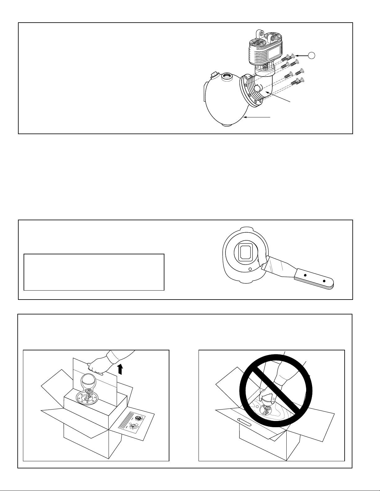
STEP 2 - Head Removal
Page 4
4
a. Clean and scrape flange surface on
control body.
b. Fold the flaps of the cardboard insert together to form the handle. Remove the Head Mechanism AND
the Insert together by lifting from the shipping carton. Undo the insert from around the Head Mechanism.
IMPORTANT: Do not remove the head mechanism by grabbing float ball.
C
HEAD ASSEMBLY
CONTROL BODY
b. Remove Head Mechanism
Unscrew and remove head bolts (C). There are
eight (8) on Series 93/193 and ten (10) on Series
94/194. Remove head assembly from control
body.
STEP 3 - Installing Replacement Head Mechanism
CORRECT
INCORRECT
IMPORTANT: Care must be taken not to
damage flange surfaces. Nicks, scrapes
or gouges may cause the flange to leak
when in service.
Page 5

5
92-68 FLANGE GASKET
150-14 FLANGE GASKET
FLOAT STOP PLATE
c. Slide flange gasket (150-14 for Series
93/193 units and 92-68 for Series 94/194
units) over float ball and float stop plate.
HEAD ASSEMBLY
d. Install head assembly by carefully inserting
float ball into control body.
Control Body
(93 Float Chamber Shown)
C
e. Align gasket and install head bolts (C).
Page 6

6
E
F
g. Using a screwdriver and pipe wrench
remove float block dowel (E) and plug (F).
Install pipe plug included with unit in opening.
f. Using a torque wrench, tighten head bolts
in an alternating star pattern.
Tighten to 14-20 ft•lbs for Series 93 models.
Tighten to 17-21 ft•lbs for Series 94 models.
STEP 4 - Reconnect Switch Assembly Wiring
TOWER TUBE
SWITCH
ASSEMBLY
SWITCH
COVER
TERMINAL
PANELS
CONDUIT
CONNECTOR
FITTING
HUB
B
A
For Replacement Heads with Switches
(-HD Models)
• Reattach the conduit connector and
wires to the integral fitting hub.
• Reconnect wiring to terminal panel in
exactly the same position as removed.
• Replace switch cover and fasten with two
screws (A).
For Replacement Heads without Switches
(-HDLS Models)
• Carefully slide switch assembly over
tower tube and secure with four hex
nuts (C).
CAUTION
The plug and rod must be reinstalled before control is shipped
installed on the boiler, and removed after boiler is placed and
installed.
Failure to follow this caution may damage the float and operating
mechanism.
!
Page 7

7
STEP 6 - Testing
a. Turn on power to boiler and pump circuits.
With the boiler empty, the pump should turn on
(5 or 5-M switch models) or the valve open (7B or
7B-M switch models). The burner should remain
off and boiler should begin to fill with water.
b. For Automatic Reset Models
When water level in the gauge glass is approximately
1 3/8" (35mm) above the horizontal cast line, the
burner should turn on.
For Manual Reset Models
When water level in the gauge glass is approximately
1 3/8" (35mm) above the horizontal cast line,
press the manual reset button and the burner should
turn on.
c. For 5 or 5-M Switch Models
When water level in the gauge glass is approximately
2 3/16" (56mm) above the horizontal cast line, the
pump should turn off.
For 7B or 7B-M Switch Models
When water level in the gauge glass is approximately
2 3/16" (56mm) above the horizontal cast line, the
valve should be closed.
d. With the water in the boiler at its normal level and
burner on, SLOWLY open the blow-down valve
until it is fully open. As the water level in the gauge
glass begins to drop, verify that the following occurs.
For 5 or 5-M Switch Models
When water level drops to approximately 1 1/8"
(29mm) above the horizontal cast line, the pump
should turn on. When water level drops to the
horizontal cast line, the burner should turn off.
For 7B or 7B-M Switch Models
As the water level drops, the valve should begin to
open. When the water level drops to approximately
1 1/8" (29mm) above the horizontal cast line, the
valve should be full open.
When the water level drops to the horizontal cast
line, the burner should turn off.
e. Close the blow-down valve after burner turns off
and restore water level to normal operating level.
f. Repeat testing procedure several times to ensure
proper operation of control.
g. After testing and verification of control operation,
the boiler can be returned to service.
– Dimensions shown are typical.
– The following testing procedure is only meant to serve
as a verification of proper operating sequence.
CAUTION
Immediately turn off all power if the burner turns on
with no water in the gauge glass. Investigate further
before continuing procedure.
!
CAUTION
If pump does not turn off or valve close, turn off
water supply to boiler. Investigate further before
continuing procedure.
!
TROUBLESHOOTING
Erratic operation of the control is the most common symptom
that occurs. Erratic operation can be defined as pump and/or
burner switches not switching at proper levels. Refer to the
following list of items to check if the control is not operating
properly.
1. Float Ball is Crushed
Crushed floats are typically caused by improper
blow-down. Drain piping from blow-down valve to drain
should be checked for proper pitch and the blow-down
procedure followed when blowing down the control.
Purchase and install a new float ball after investigating
and correcting the problem.
2. Float Ball is Filled with Water
The seam weld on the float can sometimes deteriorate.
This can be caused by the type of chemical treatment
used in the boiler. While this is a rare occurrence, the
chemical treatment supplier should be consulted to
determine if a reaction could occur. Purchase and install
a new float ball after investigating and correcting the problem.
3. Float Arm Springs are Bent
The pivot springs located on either side of the float rod
should be flat and straight. If they become bent, the usual
cause is mishandling of the unit during installation or
improper blow-down.The control should never be picked
up by the float ball or allowed to hang from the bowl by the
float. Drain piping from blow-down valve to drain should be
checked for proper pitch and the blow-down procedure
followed when blowing down control. Purchase and install
new control or head mechanism after investigating and
correcting the problem.
4. Switch Contact Springs Broken
The contact springs can break if the electrical rating is
exceeded. Purchase and install new switch assembly
or
head mechanism after investigating and correcting
the problem.
5. Switch Contact Springs Misaligned
Misalignment of the contact arms is usually associated
with damage to the control during shipment or installation.
Purchase and install new switch assembly or head
mechanism after investigating and correcting the problem.
6. Internal (Wetted) Parts Dirty
The internal parts can operate improperly if dirt, scale or
rust is allowed to build. This condition can be a result of
not blowing down the control as recommended and/or
improper boiler water chemical treatment. Purchase and
install new control or head mechanism after investigating
and correcting the problem.
Page 8

MAINTENANCE
!
BLOW DOWN PROCEDURE:
SCHEDULE:
Blow down control as follows when boiler is
in operation.
• Daily if operating pressure is above 15 psi.
• Weekly if operating pressure is below 15 psi.
NOTE
More frequent blow-down may be necessary
due to dirty boiler water and/or local codes.
• Remove head assembly and inspect water
side components annually. Replace head
assembly if any of the internal components are
worn, corroded or damaged or if control no longer
operates properly.
• Inspect the float chamber and equalizing piping
annually. Remove all sediment and debris.
NOTE
The control may need to be inspected and cleaned
more frequently on systems where there is the
potential of excessive scale or sludge build-up.
This includes systems:
• With high raw water make-up
• With no condensate return
• With untreated boiler water
• Where significant changes have been
made to the boiler-water chemical
treatment process
• With oil in the boiler water
CAUTION
To prevent serious personal injury from steam
pipe blow down, connect a drain pipe to the
control opening to avoid exposure to steam
discharge.
Failure to follow this caution could cause
personal injury.
When blowing down a control at pressure, the blow
down valves should be opened slowly.The piping
needs to be warmed up and stagnant water in the
drain piping needs to be pushed out. Suddenly
opening a blow down valve causes steam to condense, which can create water hammer. Damage to
components can occur when water hammer occurs
due to improper blow down piping.
For these reasons, McDonnell & Miller recommends
a dual valve blow-down system for each control.
Blow down the control when the water in the boiler
is at its normal level and the burner is on.
NOTE: Refer to page 2 for switch operating points.
• Open upper valve (#1)
• Slowly open the lower valve (#2)
• Water in the sight glass should lower.
• As the water in the sight glass lowers, the
pump should turn on.
• As the water continues to lower in the sight
glass, the burner should turn off.
• Slowly close the lower valve (#2).
• Close the upper valve (#1)
• The water level in the sight glass should rise, first
turning on the burner and then turning off the pump.
NOTE: On manual reset models, the reset button
will need to be pressed after the water level has
been restored before the burner will operate.
Replace head mechanism every 5 years.
More frequent replacement may be required when
severe conditions exist.
Replacement parts are available from your local
authorized McDonnell & Miller Distributor.
The use of parts or components other than those
manufactured by McDonnell & Miller will void all
warranties and may affect the units compliance with
listings or regulating agencies.
Xylem Inc.
8200 N. Austin Avenue
Morton Grove, Illinois 60053
Phone: (847) 966-3700
Fax: (847) 965-8379
www.xyleminc.com/brands/mcdonnellmiller
McDonnell & Miller is a trademark of Xylem Inc. or one of its subsidiaries.
© 2012 Xylem Inc. MM-413F August 2012 Part No. 210417
NOTE
If this sequence of operation does not occur as
described, immediately close all the valves, turn off the
boiler and correct the problem. Inspection/cleaning of
the float mechanism may be required to determine why
the control was not working properly. Retest the control
after the problem has been identified and corrected.
Valve #1
Valve #2
 Loading...