

Page 1
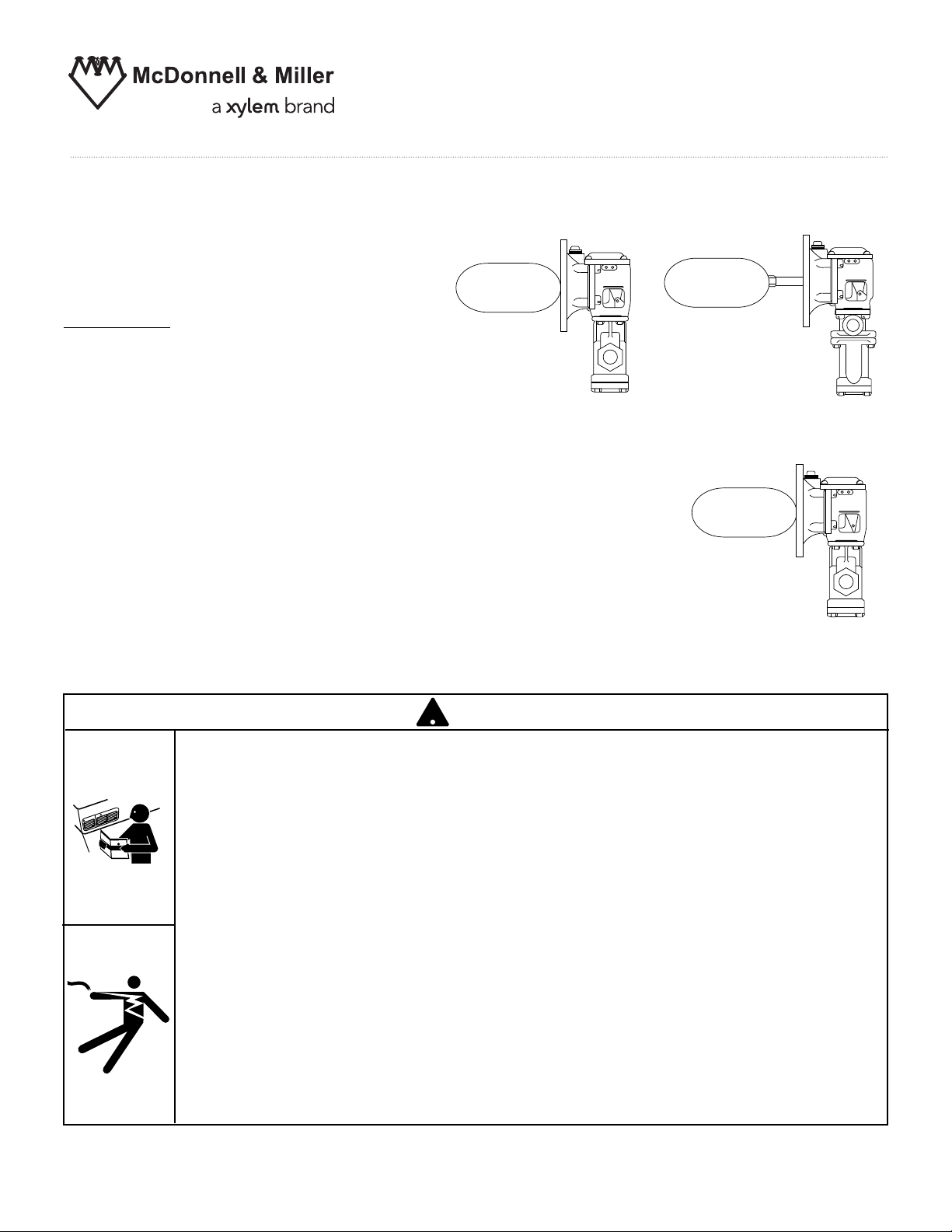
Series 851, 851-S and 847
Make-Up Water Feeders
Applications:
For receiver tanks in industrial or
commercial applications.
INSTRUCTION MANUAL
MM-320
C
Series 851
WARNING
!
• Before using this product read and understand the installation instructions.
• Save the installation instructions and these maintenance and replacement instructions
CAUTION
ARNING
W
for future reference.
• All work must be performed by qualified personnel trained in the proper application, installation, inspection, and maintenance of HVAC systems in accordance with all applicable
codes and ordinances.
Series 851-S
Series 847
California Proposition 65 warning! This product contains chemicals known to the
•
state of California to cause cancer and birth defects or other reproductive harm.
•
Previous controls should never be installed on a new system. Always install new
controls on a new boiler or system.
Failure to follow this warning could cause property damage, personal inj ury or death.
CAUTION:
•
A more frequent replacement interval may be necessary based on the condition of
the unit at time of inspection. McDonnell Miller s warranty is one (1) year from date
of installation or two (2) years from the date of manufacture.
!
&
'
Page 2
2
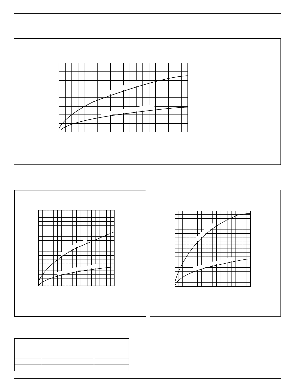
Capacities
DIFFERENTIAL PRESSURE IN POUNDS PER SQ. IN.
(Water pressure less boiler pressure)
4,000
lbs./hr.
BOILER
Btu/Hr.
(K-Calories/Hr.)
4,000,000
(15,800)
3,000,000
(11,900)
2,000,000
(7,900)
1,000,000
(4,000)
116
(1137)
87
(853)
58
(569)
29
(284)
16,000
12,000
8,000
4,000
000
BOILER
hp
(Kilowatts)
STEAM
Sq. Ft.
3,000
2,000
1,000
0
psi
(1814)
(kg/hr.)
(1361)
(907)
(454)
(0)
0102030405060708090100
(kg/cm
2
)
(0) (.7) (1.4) (2.1) (2.8) (3.5) (4.2) (4.9) (5.6) (6.3) (7.0)
C
a
p
a
c
i
t
y
a
t
S
w
i
t
c
h
C
u
t
-
O
f
f
M
a
x
i
m
u
m
C
a
p
a
c
i
t
y
C
a
p
a
c
i
t
y
a
t
S
w
i
t
c
h
C
u
t
-
O
f
f
M
a
x
i
m
u
m
C
apacity
FEEDER DISCHARGE
DIFFERENTIAL PRESSURE IN POUNDS PER SQ. IN.
(Water pressure less boiler pressure)
10,000
lbs./hr.
9,000
8,000
7,000
6,000
5,000
4,000
3,000
2,000
1,000
0
0psi 10 20 30 40 50 60 70 80 90 100
(0)(kg/cm
2
) (.7) (1.4) (2.1) (2.8) (3.5) (4.2) (4.9) (5.6) (6.3) (7.0)
(4536)
(kg/hr.)
STEAM
Sq.Ft.
BOILER
hp
(Kilowatts)
40,000
36,000
32,000
28,000
24,000
20,000
16,000
12,000
8,000
4,000
0
290
(2843)
261
(2559)
232
(2274)
203
(1990)
174
(1706)
145
(1421)
116
(1137)
87
(853)
58
(569)
29
(284)
0
(4082)
(3629)
(3175)
(2722)
(2268)
(1814)
(1361)
(907)
(454)
(0)
M
a
x
i
m
u
m
C
a
p
a
c
i
t
y
C
a
p
a
c
i
t
y
a
t
S
w
i
t
c
h
C
u
t
-
O
f
f
Max. Water Supply Max. Valve
Series Pressure, psi Pressure, psi
851 150 35
851-S 100 35
847 150 25
Operation
Series 851
Series 847
Series 851-S
Page 3

3
INSTALLATION –
TOOLS NEEDED:
One (1) pipe wrench and one (1) socket wrench.
STEP 1 - Preparation
A
Drain the water in the receiving tank to a level
which is below the control opening (A). Allow the
boiler to cool to 80˚F (27˚C) and allow the
pressure to release to 0 psi (0 bar).
C
D
Use a socket wrench to secure the feeder (D)
to the receiver tank with the six
3
/8” - 16
bolts through mounting flange (C) and
tighten to 18 ft•lb (24 N•m).
STEP 2 - Install the Control Unit
Mounting Flange Dimensions
B.C.
O.D.
Float
O.D. B.C. C D Diameter
6
11
⁄16 (170) 53⁄4 (146) 67⁄16 (11.1) 43⁄4 (121)
Series 851, 851-S and 847
Dimensions, in. (mm)
“C” - number of mounting holes
“D” - size of mounting holes
Page 4

STEP 3 - Install the Piping
Piping the Valve on Series 847 and 851
a. Follow the drawing to the right for piping the
valve to boiler and city water supply. When
piping the valve remember to leave room for
servicing the valve. This will aid in troubleshooting the valve and piping in the future.
Piping the Valve on Series 851-S
a. Follow the drawing to the right for piping the
valve to the boiler and city water supply.
When piping the valve remember to leave
room for servicing the valve. This will aid in
troubleshooting the valve and piping in
the future.
Hand By-Pass Valve
By-pass
Hand By-Pass
Valve
CAUTION
Before turning
on city water
pressure be
sure to open
this valve
Swing Check Valve
Connect to return
header on boiler
side of all valves
Swing Check Valve
Strainer
Basket
Assembly
City Water
Supply
Supply
Valve
City Water
Supply
Supply To
Feeder
MAINTENANCE
SCHEDULE:
• Disassemble and inspect annually. Replace the
water feeder if it is worn, corroded, or if
components no longer operate properly.
• Replace control every 15 years. More frequent
replacement may be required when severe
conditions exist such as surging water levels and
use of water treatment chemicals.
By-pass
Connect to return
header on boiler
side of all valves
Strainer
Basket
Assembly
• Disassemble and inspect the strainer screen
annually. Thoroughly clean the strainer screen
or replace.
• Remove and inspect cartridge annually.
Thoroughly clean by rinsing with clear water
or replace.
Xylem Inc.
8200 N. Austin Avenue
Morton Grove, Illinois 60053
Phone: (847) 966-3700
Fax: (847) 965-8379
www.xyleminc.com/brands/mcdonnellmiller
McDonnell & Miller is a trademark of Xylem Inc. or one of its subsidiaries.
© 2013 Xylem Inc. MM-320C July 2013 Part No. 210528
 Loading...