

Page 1
INSTRUCTION MANUAL
IM180
Standard and Dual
Voltage Motors
INSTALLATION, OPERATION AND MAINTENANCE INSTRUCTIONS
Page 2

2 CentriPro Motors Installation, Operation and Maintenance Manual
Page 3

Table of Contents
Table of Contents
Safety Instructions ................................................................................................................................2
Handling and Installation .....................................................................................................................3
Submersible Motor Performance Guidelines For Use On Variable Frequency Drives .............................4
Pre-Installation .....................................................................................................................................5
Maintenance ......................................................................................................................................... 6
Operation ............................................................................................................................................. 6
Figures 1, 2 and 3; Tables 1 and 2 .........................................................................................................7
Figure 4; Table 3 ...................................................................................................................................8
Table 4 & 5 - Three Phase Motor Data ........................................................................................... 9, 10
Three Phase 75º C Cable, 60 Hz .........................................................................................................11
Troubleshooting of Submersible Motors .............................................................................................. 12
Motor Cooling, Temperature Ratings ................................................................................................. 13
Limited Warranty ................................................................................................................................ 14
Owners Information
Complete this information for your records.
Model number and serial number may be found
on the tag mounted to the pump casing.
Pump Model Number
Pump Serial Number
Control Model Number
___________________________________________
Dealer
Dealer phone number
Date of purchase
Date of installation
Current Readings at Startup:
1 Ø 3 Ø L1-2 L2-3 L3-1
Amps: Amps:
Volts: Volts:
______________________________
_______________________________
____________________________
______________________________
__________________________________
________________________________
CentriPro Motors Installation, Operation and Maintenance Manual 1
Page 4
DANGER
WARNING
CAUTION
Safety
I. Safety
TO AVOID SERIOUS OR FATAL PERSONAL INJURY OR MAJOR PROPERTY DAMAGE, READ
AND FOLLOW ALL SAFETY INSTRUCTIONS IN MANUAL AND ON PUMP.
THIS MANUAL IS INTENDED TO ASSIST IN THE INSTALLATION AND OPERATION OF THIS
UNIT AND MUST BE KEPT WITH THE PUMP.
This is a SAFETY ALERT SYMBOL. When you see this symbol on the pump or in
the manual, look for one of the following signal words and be alert to the potential
for personal injury or property damage.
Warns of hazards that WILL cause serious personal injury, death or major property
damage.
Warns of hazards that CAN cause serious personal injury, death or major property
damage.
Warns of hazards that CAN cause personal injury or property damage.
NOTICE: INDICATES SPECIAL INSTRUCTIONS WHICH ARE VERY IMPORTANT AND
MUST BE FOLLOWED.
THOROUGHLY REVIEW ALL INSTRUCTIONS AND WARNINGS PRIOR TO PERFORMING
ANY WORK ON THIS PUMP.
MAINTAIN ALL SAFETY DECALS.
2 CentriPro Motors Installation, Operation and Maintenance Manual
Page 5

CAUTION
Handling and Installation
II. Handling and Installation
1. Do not use lead wires to pull, lift or handle the motor. The lead wires should be protected during
storage, handling, moving and installation of the motor.
2. Inspect the motor to determine that it is the correct HP, voltage and size for the job and that there
is no shipping damage.
3. The factory-installed water in the motor is supplied with antifreeze capable of temperatures to -30º
C (-22º F). Do not install, transport or store below these temperatures. If storage is necessary below
these temperatures, drain the water from the motor.
4. After long periods of idleness and on all new installations, check the electrical resistance and megger the motor with lead wires connected. The insulation resistance should have a value of at least 5
megohms at installation and at least 1 megohm after running.
5. Verify motor is filled with clean water before installing. The warranty is void if this is not done.
Also check the tightness of all water filling and drain plugs, mounting bolts and cable connections.
6. Do not hammer the shaft, coupling or slinger since this may damage the thrust bearing. Check the
rotation of the motor by hand to insure that it turns freely.
7. Do not drop the bottom end of the motor in the dirt or mud since this may plug up the diaphragm
opening.
8. If motor is to be installed horizontally, make sure that the lead wires are at the 12 o'clock position
when facing the motor shaft (in horizontal position).
9. Before installation, verify that the motor is the correct required voltage. (If not, refer to step 12
below; CHANGING MOTOR VOLTAGE.)
10. Check that winding coil resistance in each phase is equal to values in Table 2 or 4.
11. Select the proper overload relay or heaters per Table 3 or 6.
12. CHANGING MOTOR VOLTAGE
Motor voltage can be changed from 460V to 230V or from 230V to 460V by changing the voltage
plug as follows:
A. Remove the existing voltage sticker from the voltage plug.
B. Remove the two 5/32" Allen screws and carefully pull the voltage plug up and out using two
screwdrivers as shown in Figure 1.
C. Check to be sure the new plug is not damaged and that it is the correct required voltage.
D. Verify that the plug and the socket in the motor housing are clean and dry.
E. Coat the sealing surface of the voltage plug with Dow Corning 732-3 or comparable silicone
sealant as shown in Figure 2.
F. Insert the new voltage plug as shown in Figure 3. Note that the top of the numerals are toward
the shaft and the bottom is near the outer side of the motor.
G. Secure the new voltage plug into the motor with the two Allen screws. Tighten the screws until
the outer stainless steel portion of the plug contacts the motor housing.
H. Mount the new voltage sticker furnished with the new plug on the motor control panel or
starter.
13. Always verify that the voltage of the plug installed in the motor is the correct
required voltage even if you made no change. Improper installation of the voltage
plug voids all warranties.
CentriPro Motors Installation, Operation and Maintenance Manual 3
Page 6

Submersible Motor Performance Guidelines For Use On Variable Frequency Drives
III. Submersible Motor Performance
Guidelines For Use On Variable
Frequency Drives
The CentriPro motor has been used extensively with variable frequency drives. As with any modified application, there are considerations to evaluate when using an inverter, or Variable Frequency
Drive (VFD), to operate a submersible motor. To ensure reliable operation, the following guidelines
must be followed when using the 2 pole CentriPro submersible motor with a VFD.
1. Proper, class 10, quick trip, overload protection must be used at all times. As a minimum, Overloads must trip at five times full load current within 10 seconds on any phase.
2. A minimum of 1.5 times full load current should be available to initially start the motor if needed.
3. Minimum operating frequency is 30 hertz
4. Minimum Speed: 0.5 x Synchronous Speed (Example: 3600 RPM x .5 = 1800 RPM)
5. Maximum Speed: 1.00 x Full Load Speed
6. Ramp-up Time: Maximum 1 second to reach 30 Hz, maximum 4.0 seconds to reach current limit
and rated speed
7. Ramp down time: from minimum frequency to power shutoff shall be four (4) seconds.
8. At the minimum speed (see #3), one-half foot per second water velocity, at rated temperature,
must be maintained past the motor. Velocity in excess of 10 feet per second is not recommended.
9. The VFD must maintain a constant volts to Hertz ratio. The controls must be rated the same as
motor nameplate.
10. The output of the VFD must have a filtering or line conditioning device installed to eliminate
voltage waveform phenomenon that might adversely affect motor components and elements.
Power at the motor leads must be clean, free of high voltage transients, harmonics, and within
the voltage range of the motor (1000V peak at more than .2 microsecond rise time).
11. All other requirements and restrictions for the CentriPro submersible motor apply.
These are general guidelines for the operation of the 2 pole CentriPro submersible motor on
AC Inverters incorporating IGBT type switching devices and starting from zero rotation with a
limited, immediate, hydraulic load.
4 CentriPro Motors Installation, Operation and Maintenance Manual
Page 7

IV. Pre-Installation
1. Maximum Water Temperature:
A) 35º C (95º F): 6" (5 – 40 HP) motors.
B) 25º C (77º F): 6" (50 HP), 8" and 10" motors.
2. PH content of the water between: 6.5–8
3. Maximum Chlorine Content: 500 PPM
Maximum Sulfuric Acid Iron Content: 15 PPM
Maximum Flourine Content: 0.8 PPM
Maximum Electric Conductivity: 118 μMHO/INCH
4. Maximum Sand Content: 50 PPM
5. Proper approved three phase overload protection. Class 10, quick trip overloads are mandatory.
See Table 4, 6 or 7.
6. Proper fusing for motor circuit protection. See Table 5.
7. Proper Line Voltage During Running Conditions:
460V ±10%, i.e. 506 to 414 volts
230V ±10%, i.e. 253 to 207 volts
For a 60 cycle system measured at motor lead wire terminal.
(Voltage drop of cable should be considered by user.)
Current unbalance between legs should not exceed 5% of the average.
8. Proper sizing of motor (current, thrust, voltage, etc.) and a 10 ft. clearance from the bottom of
the well are required.
9. In the case of horizontal installation, the motor is to be rigidly aligned with the pump and firmly
mounted to prevent any load on the shaft and bearings and to avoid any damaging vibrations to
the motor. Also, see #8 in Section II.
10. The motor must always be immersed in water so that a flow velocity of cooling water at a rate of
0.5 feet per second flows past any and all parts of the motor. The motor will not operate in mud
or sand.
11. The power cables shall be sized large enough so that at rated current there will be less than a 5%
voltage drop. Cables must be waterproof submersible type. See Table 8.
12. For 3Ø motors a balanced and properly sized transformer bank shall be provided. Improper electrical supply (for example, phase converter, V-connection transformer, etc.) or connections will
void the warranty.
13. Single phase protection is recommended for protection of the installation. Any failure due to
single phasing of the incoming voltage causing the motor to fail will void the warranty.
14. Lightning arrestors are recommended in the interest of protecting the control panel, as well as the
insulation system of the motor. Any motor failure due to lightning or other Acts of God will void
the warranty.
15. Provide waterproof insulation splices between all lead wires and well cables.
16. In the event that a reduced voltage starter is used to start the motor, the following should be verified:
A. Correct quick trip ambient compensated overloads are incorporated.
B. Proper short circuit protection is utilized.
C. The torque required by the motor and pump package is attainable by this type starter.
D. The lead arrangement of the motor is acceptable with the proposed starter load connections.
Pre-Installation
CentriPro Motors Installation, Operation and Maintenance Manual 5
Page 8

Pre-Installation (continued), Maintenance and Operation
E. Verify that if any time delay relays are used in switching contactors in and out, that the time
settings are not too long; this could damage the motor.
F. If a manual auto transformer starter is used, don't wait too long to go into the "Run" condition
and don't "tease" the contacts. Double check Table 4 for correct protection.
17. Single Phase Motors (5-15 HP)
Proper connections and correct capacitors and relays are necessary for single phase motor starting
and running.
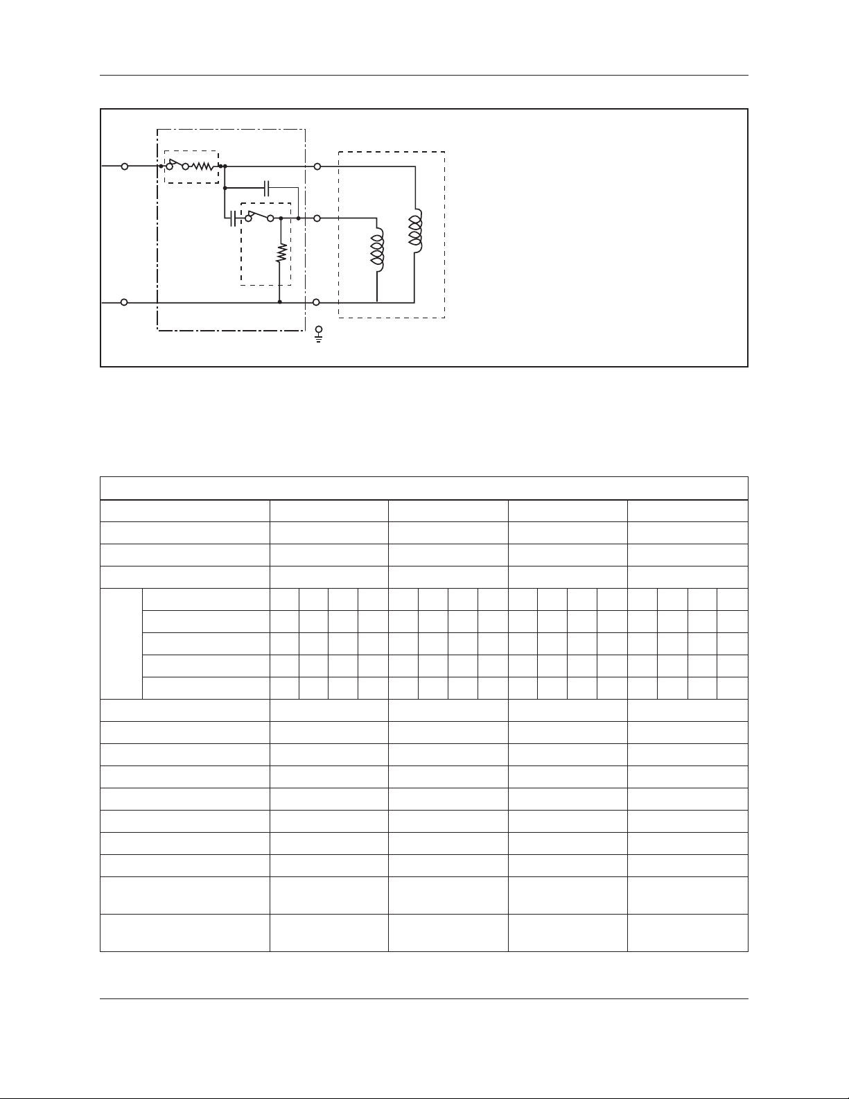
Connection Diagram: See Figure 1.
See recommended capacitors in Table 3 and recommneded control boxes in Table 1.
18. Do not expose motor leads to air. Leads must be submerged for cooling.
V. Maintenance
There are no bearings that need oil or grease. The motor, being inaccessible, should be monitored
through its electrical connections.
1. Measure and record operating current and voltage.
2. Measure and record the motor insulation resistance. Any resistance of less than 5 megohm
(5,000,000) for a new motor should be evaluated or checked further by a qualified service shop.
3. Lightning arrestors and/or surge capacitors will help prevent damage to the control box, cables and
motor.
4. Single phase protection will help in preventing motor failure due to adverse incoming primary
power.
5. Based on the values obtained in 1 and 2 above and the output flow rates and pressures of the pump,
a complete picture of total performance can be obtained. This can be used to determine any pump
and motor maintenance and overhauling which might be required.
6. If the motor is to be stored, protect the unit from freezing by storing in an area with a temperature
higher than -30º C (-22º F).
VI. Operation
1. After energizing the motor, check the flow and pressure of the pump to make sure that the motor
is rotating in the correct direction. To correct a wrong rotation, switch any two of the three cable
connections. (Three phase motor only.)
2. When starting the pump for the first time, inspect the water for sand. If sand appears, then continue to pump until the water clears up; otherwise, sand will accumulate in the pump stages and
will bind or freeze the moving parts if water is allowed to flow back down the well.
3. During testing or checking rotation (such as "bumping" or "inching") the number of "starts" should
be limited to 3, followed by a full 15 minute cooling-off period before any additional "starts"
are attempted. Depending on the depth of the well and/or method of checking, these rotational
checks or "starts" may actually be full-fledged starts. If this is the case, then a full cooling-off period of 15 minutes is required between this type of start.
4. For automatic (pilot device) operation, the motor should be allowed to cool for 15 minutes between starts.
5. Input voltage, current and insulation resistance values should be recorded throughout the life of
the installation and should be used as a form of preventive maintenance.
Table 2 — Resistance Data
6 CentriPro Motors Installation, Operation and Maintenance Manual
Page 9
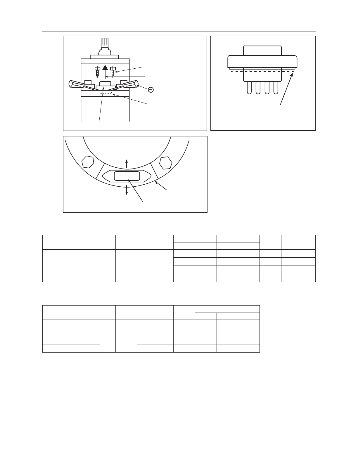
Allen Screws
Pull up straight
Screwdriver
Socket in the
motor housing
Operation (continued)
Dow Corning 732-3 or
comparable silicone sealant
VOLTAGE PLUG
Figure 1
Top
Figure 2
460V
Motor Outer side
Bottom
Table 1 — 6" Single Phase Motors and Required Control Boxes
Motor
Order No. vs Flange Dia.
HP kW Volts
6M051 5 3.7 24 4987 27.5 5735 124 CB05MC
6M071 7.5 5.5
6M101 10 7.5 50 10135 58 11830 202 CB10MC
6M151 15 11 72 15180 85 18050 275 CB15MC
Motor Dia.
230 6" x 6" 1.15
Voltage Numeral
(460V or 230V)
S.F.
Amps Watts Amps Watts Amps Order No.
36 7675 41 8950 167 CB07MC
Figure 3
Rated Input Service Factor
L.R. Control Box
Table 2 — 6" Single Phase Resistance, KVA, Efficiency
Motor
Order No. Efficiency % Code R -Y B - Y R- B
HP kW Volts Phase
F.L. KVA
6M051 5 3.7 74.8 G 2.172 0.512 2.627
6M071 7.5 5.5
230 1
72.9 F 1.401 0.400 1.774
6M101 10 7.5 73.6 E 1.052 0.316 1.310
6M151 15 11 73.7 D 0.678 0.230 0.850
CentriPro Motors Installation, Operation and Maintenance Manual 7
Resistance - Ohms
Page 10
Operation (continued)
Connection Diagram For Single Phase Motors
Starter Box
Line 2
Blue
O.L.B.
B
CR
Motor
SYMBOL
Motor : Single Phase Induction Motor
M.C. :Main Coil
A.C. :Auxiliary Coil
B:Motor Lead Black
R:Motor Lead Red
Y:Motor Lead Yellow
G:Motor Ground Lead Green
CR :Running Capacitor
CS : Starting Capacitor
S.R.:Starting Voltage Realy
O.L.B. :Overload Protection Circuit
Line 1
Yellow
CS
S.R.
R
M.C.
A.C.
Y
G
Table 3 — Performance Data of Single Phase Submersible Motors
Breaker
Figure 4
6" MOTOR, 3600 RPM
Output
Voltage-Frequency 230V / 60 Hz 230V / 60 Hz 230V / 60 Hz 230V / 60 Hz
No Load Current
No Load Loss
Load
Current
Efficiency
Load
Power Factor
Characteristics
Slip
Full Load Torque
Breakdown Torque
Locked Rotor Torque
Locked Rotor Current
Locked Rotor Code
Rated Input
Current at SF 1.15
Input at SF 1.15
Specifications of
Running Capacitor
Specifications of
Starting Capacitor
(HP)
5 7½ 10 15
(A)
8.8 8.3 12.0 16.1
(W)
1184 1428 1544 2050
(%)
50 75 100 115 50 75 100 115 50 75 100 115 50 75 100 115
(A)
14.6 18.9 24 27.5 19.5 26.7 36 41 25.5 35.5 50 58 38.1 52.7 72 85
(%)
66.2 72.2 74.8 74.8 67.6 72.5 72.9 71.5 67.8 73.1 73.6 72.0 70.8 74.7 73.7 71.3
(%)
84.0 89.0 91.2 92.0 92.5 94.5 94.9 94.3 88.9 91.8 93.2 93.5 90.2 92.7 93.2 92.4
(%)
1.5 2.2 3.0 3.6 1.8 2.9 4.2 5.5 1.7 2.8 4.1 5.2 2.1 3.3 4.9 6.2
(ft•lbs)
7.53 11.42 15.23 23
(ft•lbs)
15.5 22.0 27.4 45
(ft•lbs)
12.5 18.3 21.3 34
(A)
124 167 202 275
(KVA)
G F E D
(W)
4987 7675 10135 15180
(A)
27.5 41 58 85
(W)
5735 8950 11830 18050
440 VAC 440 VAC 440 VAC 440 VAC
30μFD 40μFD 50μFD 70μFD
330 VAC 330 VAC 370 VAC 370 VAC
200μFD 250μFD 350μFD 450μFD
8 CentriPro Motors Installation, Operation and Maintenance Manual
Page 11

Table 4 — 6" - 10" Three Phase Motors, 200, 230, 460 and 575 Volt
Operation (continued)
Motor
Order No.
6M058 5 3.7 200
6M052 5 3.7 230 15.0 4857 17.0 5520 110
6M054 5 3.7 460 7.5 4857 8.5 5520 55
6M078 7.5 5.5 200 25.4 7180 28.5 8230 158
6M072 7.5 5.5 230 22.0 7127 26.0 8140 144
6M074 7.5 5.5 460 11.0 7127 13.0 8140 72
6M108 10 7.5 200 33.3 9360 37.2 10700 236
6M102 10 7.5 230 29.0 9407 33.0 10730 208
6M104 10 7.5 460 14.5 9407 16.5 10730 104
6M158 15 11 200 47.4 13700 53.5 15710 347
6M152 15 11 230 42.0 13700 46.0 15800 320
6M154 15 11 460 21.0 13700 23.0 15800 160
6M208 20 15 200 61.2 18040 69.5 20820 431
6M202 20 15 230 54.0 17930 60.0 20650 392
6M204 20 15 460 27.0 17930 30.0 20650 196
6M258 25 18.5 200 77.3 22740 87.5 26190 578
6M252 25 18.5 230 68.0 22470 76.0 25800 530
6M254 25 18.5 460 34.0 22470 37.0 25800 265
6M308 30 22 200 91.8 27000 104.0 31120 674
6M302 30 22 230 82.0 27130 94.0 31160 610
6M304 30 22
6M404 40 30 53.0 35530 60.0 41100 340
66M504 50 37 70.0 45210 79.0 52380 465
86M504 50 37
86M604 60 45 80.0 52850 90.0 60900 510
8M754 75 55
8M1004 100 75 127.0 87600 145.0 101300 795
8M1254 125 90 160.0 110800 180.0 126000 980
8M1504 150 110 195.0 130700 220.0 152000 1060
10M2004 200 150 10 "x 10" 235.0 171100 270.0 198600 1260
5-30 HP, 3 Phase 230 and 460 Motors have adjustable voltage feature, change voltage plugs to convert from 230V to 460V operation.
Spare Change Plug Order No's are: PLUG-230V or PLUG-460V.
HP kW Volts
460
Motor Dia. vs
Flange Dia.
6" x 6"
8" x 6"
8" x 8"
S.F.
1.15
Rated Input Service Factor
Amps Watts Amps Watts
17.5 4910 19.5 5610 124
41.0 27130 47.0 31160 305
65.0 44360 73.0 51000 435
96.0 65900 109.0 76100 650
L.R.
Amps
CentriPro Motors Installation, Operation and Maintenance Manual 9
Page 12

Operation (continued)
Table 5 — 6" - 10" Three Phase Resistance, KVA, Efficiency, Fuses
Motor
Order No. Efficiency % Code Resistance Standard Dual Ele.
HP kW Volts Phase
F.L.
6M058 5 3.7 200 75.9 K 0.618 50 25
6M052 5 3.7 230 76.8 K 0.806 45 20
6M054 5 3.7 460 76.8 K 3.050 25 10
6M078 7.5 5.5 200 77.9 J 0.504 80 40
6M072 7.5 5.5 230 78.5 J 0.651 70 30
6M074 7.5 5.5 460 78.5 J 2.430 35 15
6M108 10 7.5 200 79.7 K 0.315 100 50
6M102 10 7.5 230 79.3 K 0.448 90 40
6M104 10 7.5 460 79.3 K 1.619 45 20
6M158 15 11 200 81.7 K 0.213 175 70
6M152 15 11 230 81.7 K 0.312 150 60
6M154 15 11 460 81.7 K 1.074 70 30
6M208 20 15 200 82.7 J 0.189 200 90
6M202 20 15 230 83.2 J 0.258 175 70
6M204 20 15 460
83.2 J 0.861 90 35
3
6M258 25 18.5 200 82.0 K 0.146 250 110
6M252 25 18.5 230 83.0 K 0.210 225 90
6M254 25 18.5 460 83.0 K 0.666 110 45
6M308 30 22 200 82.9 J 0.119 300 125
6M302 30 22 230 82.5 K 0.166 250 100
6M304 30 22 82.5 K 0.554 125 50
6M404 40 30 84.0 H 0.446 175 70
66M504 50 37 82.5 J 0.388 225 90
86M504 50 37 84.1 H 0.331 200 90
86M604 60 45
84.7 H 0.278 250 110
460
8M754 75 55 84.9 H 0.218 300 125
8M1004 100 75 85.2 H 0.164 400 175
8M1254 125 90 84.2 G 0.132 500 225
8M1504 150 110 85.6 G 0.115 600 250
10M2004 200 150 87.2 F 0.0929 800 350
KVA Line - Line Time Delay Fuse
10 CentriPro Motors Installation, Operation and Maintenance Manual
Page 13

Three Phase 75º C Cable, 60 HZ
VII.
Three Phase 75º C Cable, 60 HZ
Table 6 — Three Phase 75º C Cable, 60 Hz (Service Entrance to Motor) Maximum Length in Feet
Motor Rating 75º C Insulation - AWG Copper Wire Size
Volts HP 14 12 10 8 6 4 2 1 1/0 2/0 3/0 4/0 250 350 500
230V
60 Hz.
Single
Phase
230V
60 Hz.
Three
Phase
3 Lead
460V
60 Hz.
Three
Phase
3 Lead
5 0 100 170 260 430 680 1060 1330 1660 2070 2560 3190
7.5 0 0
10 0 0 0
15 0 0 0 0
5
7.5 0
10 0 0
15 0 0 0
20 0 0 0
25 0 0 0 0
30 0 0 0 0 0
5 590 950 1500 2360 3700 5750
7.5 410 670 1060 1670 2610 4060 6200 7610
10 300 480 770 1220 1910 2980 4580 5630 6900
15 0
20 0 0 400 640 1020 1600 2460 3020 3710 4560 5500
25 0 0
30 0 0 0
40 0 0 0
50 0 0 0 0
60 0 0 0 0 0
75 0 0 0 0 0
100 0 0 0 0 0 0
125 0 0 0 0 0 0 0 0
150 0 0 0 0 0 0 0 0 0
200 0 0 0 0 0 0 0 0 0 0
230 370 590 920 1430 2190 2690 3290 4030 4850 5870 6650 8460
140
150
330
200 310 490 760 940 1150 1420 1740 2120
120
220 340 520 660 810 1020 1250 1540
140
140 230
250 410 640 1010 1540 1900 2310 2840 3400 4120 4660 5910 7440
300 470 740 1140 1410 1720 2110 2550 3090 3510 4500 5710
180
320 510 790 970 1180 1450 1760 2120 2410 3080 3900
200
150 240
190
530 840 1320 2070 3160 3890 4760 5840 7040
520 810 1280 1960 2410 2960 3640 4400 5350
320
650 1030 1570 1950 2390 2940 3560 4330 4940
410
320 500
390 610
370 450 560 700 870 1080
390 600 750 920 1130 1370 1670 1900 2440 3100
310 490 600 730 900 1100 1330 1510 1950 2480
390 490 590 730 890 1080 1230 1580 2030
250
790 1220 1500 1840 2270 2730 3320 3760
940 1170 1430 1750 2110 2560 2910 3700 4690
830 1020 1250 1540 1860 2250 2550 3260 4120
540
430 660
820 1000 1230 1480 1810 2050 2640 3360
490 610 750
930 1120 1360 1540 1990 2520
620 770 920
620 750 910
1040 1270 1620 2040
610 740 840
1040 1330 1680
1070 1370
Lengths NOT SHADED meet the U.S. National Electrical Code ampacity for either individual conductors or jacketed 75º C cable.
Lengths SHADED meet the National Electric Code ampacity only for individual conductor 75º C cable, in free air or water. If other
cable is used, the National Electric Code as well as the local codes should be observed.
CentriPro Motors Installation, Operation and Maintenance Manual 11
Page 14

Troubleshooting of Submersible Motors
VIII. Troubleshooting of Submersible
Motors
1. Motor does not start but does not blow fuses or relay.
• No Power Supply → Replace fuses, breakers or check for loose or corroded connections and
motor lead terminals.
• Defective Connections → Correct connections.
2. Fuses or relay blow when motor starts.
• Incorrect Voltage → Apply correct voltage.
Voltage must be ±10% of rated (Nameplate).
• Incorrect Fuses or Relay → Replace with proper fuses and relay.
• Defective Capacitors → Replace with proper capacitors.
• Wrong Connections → Correct wrong connections or short circuit.
• Locked Rotor Conditions → Correct pump or well conditions.
• Insulation Resistance Down → Check the line and correct.
3. Motor runs for a while and then blows fuses or relay.
• Low Voltage or High Voltage → Apply rated voltage.
• Defective Capacitors → Replace with proper capacitors.
• Different Control Box for the Motor → Replace with proper control box.
• Defective Starting Voltage Relay → Replace with proper relay.
• Pump is Sand Clogged → Pull pump and clean well.
• Overheated Protector → Shield the control box from heat source.
The following conditions are stated to provide the owner with a list of criteria for maximum
motor life and to assure motor warranty.
12 CentriPro Motors Installation, Operation and Maintenance Manual
Page 15

Motor Cooling, Temperature Ratings
X. Motor Cooling, Temperature Ratings
Six (6) inch canned design motors from 5 – 40 HP will operate in water up to 95º
F (35º C), without any de-rating of horsepower, with a minimum flow rate of .5 ft./
sec. past the motor. 6" – 50 HP and all 8" – 10" motors can operate in 77º F (25º C)
water with .5'/sec velocity past the motor.
Minimum Flow Rates For Proper Motor Cooling
6 7 9 –
7 23 25 –
8 41 45 9
10 85 90 53
12 139 140 107
14 198 200 170
16 276 280 313
Diameter
Multiply gpm by .2271 for m3/Hr.
Multiply gpm by 3.785 for l/min.
CP = 5.5" Dia. FE = 5.38" Dia. CP = 7.52" Dia.
Well or
6" CP Motor 6" FE Motor 8" CP Motor
Sleeve
(inches)
.5'/sec. .5'/sec. .5'/sec.
GPM Required
FLOW SLEEVE
CentriPro Motors Installation, Operation and Maintenance Manual 13
Page 16

CENTRIPRO LIMITED WARRANTY
This warranty applies to CentriPro 6"-10" motors shown in this manual.
Any part or parts found to be defective within the warranty period shall be replaced at no charge to the dealer during the warranty period. The warranty
period shall exist for a period of twelve (12) months from date of installation or eighteen (18) months from date of manufacture, whichever period is
shorter.
A dealer who believes that a warranty claim exists must contact the authorized CentriPro distributor from whom the motor and control was purchased
and furnish complete details regarding the claim. The distributor is authorized to adjust any warranty claims utilizing the Customer Service Department.
The warranty excludes:
(a) Labor, transportation and related costs incurred by the dealer;
(b) Reinstallation costs of repaired equipment;
(c) Reinstallation costs of replacement equipment;
(d) Consequential damages of any kind; and,
(e) Reimbursement for loss caused by interruption of service.
For purposes of this warranty, the following terms have these definitions:
(1) “Distributor” means any individual, partnership, corporation, association, or other legal relationship that stands between CentriPro and the dealer in
purchases, consignments or contracts for sale of the subject motors and controls.
(2) “Dealer” means any individual, partnership, corporation, association, or other legal relationship which engages in the business of selling or leasing
motors and controls to customers.
(3) “Customer” means any entity who buys or leases the subject motors and controls from a dealer. The “customer” may mean an individual, partner-
ship, corporation, limited liability company, association or other legal entity which may engage in any type of business.
THIS WARRANTY EXTENDS TO THE DEALER ONLY.
Xylem, Inc.
2881 East Bayard Street Ext., Suite A
Seneca Falls, NY 13148
Phone: (866) 325-4210
Fax: (888) 322-5877
www.xyleminc.com/brands/centripro
CentriPro is a trademark of Xylem Inc. or one of its subsidiaries.
© 2012 Xylem, Inc. IM180 Revision Number 3 July 2012
Page 17

MANUAL DE LA INSTRUCCIÓN
IM180
Motores estándar
y de doble voltaje
INSTRUCCIONES DE INSTALACIÓN, OPERACIÓN Y MANTENIMIENTO
Page 18

16 CentriPro Motors Installation, Operation and Maintenance Manual
Page 19

Índice
Instrucciones de seguridad .................................................................................................................18
Manipulación e instalación ................................................................................................................19
Directrices para el desempeño del motor sumergible en su uso en
controladores de frecuencia variable ............................................................................................... 20
Pre-instalación ...................................................................................................................................21
Mantenimiento .................................................................................................................................. 22
Operación ..........................................................................................................................................22
Figuras 1, 2 y 3; Tablas 1 y 2 ..............................................................................................................23
Figura 4; Tabla 3 ................................................................................................................................24
Tabla 4 & 5 - Datos del motor trifásico .....................................................................................25 & 26
Tablas 6 - Cable trifásico de 75°C, 60 Hz ........................................................................................... 27
Localización de Falla de los Motores Sumergibles ..............................................................................28
Refrigeración del motor, calificaciones de temperatura ......................................................................29
Garantía limitada ............................................................................................................................... 30
Índice
Información para el propietario
Termine esta información para sus expedientes.
El número y el número de serie de modelo se pueden
encontrar en la etiqueta montada a la cubierta de la bomba.
Número de modelo de la bomba: __________________________
Número de serie de la bomba: _____________________________
Número de modelo de control: ____________________________
Representante: __________________________________________
Nº telefónico del representante: ___________________________
Fecha de compra:
Fecha de Instalación:
Lecturas actuales al momento del arranque:
1 Ø 3 Ø L1-2 L2-3 L3-1
Amperes: Amperes:
Voltios: Voltios:
________________________________________
_____________________________________
Motores de CentriPro Instrucciones de instalación, operación y mantenimiento
CentriPro Motors Installation, Operation and Maintenance Manual 17
Page 20

ADVERTENCIA
Instrucciones de Seguridad
I. Instrucciones de Seguridad
PARA EVITAR LESIONES PERSONALES GRAVES O FATALES, Y DAÑOS SIGNIFICATIVOS
A LA PROPIEDAD, LEA Y SIGA TODAS LAS INSTRUCCIONES DE SEGURIDAD QUE SE ENCUENTRAN EN ESTE MANUAL O EN LA BOMBA.
ESTE MANUAL TIENE LA FUNCIÓN DE ASISTIRLO EN LA INSTALACIÓN Y OPERACIÓN DE
ESTA UNIDAD Y DEBE CONSERVARSE CON LA BOMBA.
Este es un SÍMBOLO DE ALERTA DE SEGURIDAD. Cuando vea este símbolo sobre
la bomba o en el manual, busque una de las siguientes palabras de señalización y esté
alerta a las posibles lesiones personales o daños a la propiedad que puedan ocurrir.
PELIGRO
PRECAUCIÓN
AVISO: INDICA QUE EXISTEN INSTRUCCIONES ESPECIALES MUY IMPORTANTES QUE
EXAMINE COMPLETAMENTE TODAS LAS INSTRUCCIONES Y ADVERTENCIAS ANTES DE
REALIZAR CUALQUIER TRABAJO EN ESTA BOMBA.
CONSERVE TODAS LAS CALCOMANÍAS.
Advierte sobre los peligros que PROVOCARÁN lesiones graves, muerte o daños sig-
nificativos a la propiedad.
Advierte sobre los peligros que PUEDEN PROVOCAR lesiones graves, muerte o da-
ños significativos a la propiedad.
Advierte sobre los peligros que PUEDEN PROVOCAR lesiones o daños a la
propiedad.
DEBEN RESPETARSE.
18 CentriPro Motors Installation, Operation and Maintenance Manual
Motores de CentriPro Instrucciones de instalación, operación y mantenimiento
Page 21

Manipulación e Instalación
II. Manipulación e Instalación
No utilice hilos conductores para sacar, levantar o manipular el motor. Los hilos conductores de-
1.
berán permanecer protegidos durante el almacenamiento, manipuleo, desplazamiento e instalación
del motor.
Examine el motor para establecer que sea del voltaje, tamaño y HP correctos para la tarea que lo
2.
necesite y que no se hayan producido daños durante el traslado.
El agua del motor instalada de fábrica es provista de anticongelante capaz de evitar que las tempera-
3.
turas desciendan a -30 ºC (-22 ºF). No instale, transporte o almacene a temperaturas más bajas de
éstas. Si necesitara almacenar por debajo de las temperaturas antes mencionadas, drene el agua del
motor.
4. Después de períodos prolongados de inactividad en todas las instalaciones nuevas, controle la resistencia eléctrica y mida la resistencia del motor con cables conductores conectados. La resistencia
de aislamiento debe tener un valor de al menos 5 megohmios en el momento de la instalación y al
menos 1 megohmio después de estar en funcionamiento.
Verifique que el motor esté lleno con agua limpia antes de instalarlo. Si esto no se realiza, la ga-
5.
rantía no tiene validez. También controle la hermeticidad de todas las cargas de agua y los tapones
de drenaje, pernos de montaje y conexiones.
No golpee el eje, el acoplamiento o el salpicador ya que esto puede dañar el cojinete de tracción.
6.
Controle la rotación del motor manualmente para asegurarse que gire libremente.
No deje caer el extremo inferior del motor en la suciedad o el lodo ya que esto puede tapar la aber-
7.
tura del diafragma.
Si el motor se instalara de manera horizontal, asegúrese que los hilos conductores se encuentren en
8.
la posición horaria de las 12 en punto cuando enfrenten el eje del motor (en posición horizontal).
Antes de la instalación, verifique que el voltaje del motor sea el correcto. (Si no es así, consulte el
9.
paso 12 a continuación; CAMBIO DE VOLTAJE DEL MOTOR.)
10. Controle que la resistencia de la bobina enrollada en cada fase equivalga a los valores que aparecen
en la Tabla 2 o 4.
11. Seleccione el relé de sobrecarga o calentadores correctos de acuerdo con la Tabla 3 o 6.
CAMBIO DE VOLTAJE DEL MOTOR
12.
El voltaje del motor puede cambiarse de 460V a 230V o de 230V a 460V cambiando la clavija de
conexión de voltaje de la siguiente manera:
Quite la etiqueta de voltaje existente de la clavija de conexión de voltaje.
A.
B. Quite los dos tornillos Allen de 5/32" y tire con cuidado de la conexión de voltaje hacia arriba y
hacia afuera usando dos destornilladores como se muestra en la Figura 1.
Controle que la nueva clavija de conexión no se encuentre dañada y que sea del voltaje correcto.
C.
Verifique que la clavija de conexión y el tomacorriente en el cárter del motor estén limpios y
D.
secos.
Cubra la superficie de sellado de la clavija de conexión de voltaje con Dow Corning 732-3 como
E.
se muestra en la Figura 2.
Inserte la nueva clavija de conexión de voltaje como se muestra en la Figura 3. Fíjese que la parte
F.
superior de los números se encuentren hacia el eje y la parte inferior se encuentre cerca del lado
exterior del motor.
Asegure la nueva clavija de conexión de voltaje dentro del motor con los dos tornillos Allen.
G.
Ajuste los tornillos hasta que la porción exterior de acero inoxidable de la clavija se ponga en
contacto con el cárter del motor.
Adhiera una etiqueta de voltaje nueva, proporcionada con la nueva clavija, sobre la misma. La
H.
segunda etiqueta es para adherirla en el panel de control del motor o en el arrancador.
13.
PRECAUCIÓN
de conexión del voltaje incorrecto, anula todas las garantías.
Verifique siempre que el voltaje de la clavija de conexión instalada en el motor sea
del voltaje correcto aunque no realice ningún cambio. La instalación de una clavija
Motores de CentriPro Instrucciones de instalación, operación y mantenimiento
CentriPro Motors Installation, Operation and Maintenance Manual 19
Page 22

Directrices para el desempeño del motor sumergible en su uso en controladores de frecuencia variable
III. Directrices para el desempeño del
motor sumergible en su uso en
controladores de frecuencia variable
El motor CentriPro ha sido muy usado con controladores de frecuencia variable. Al igual que cualquier aplicación modificada, hay factores que se deben evaluar al usar un inversor, o Controlador
de Frecuencia Variable [Variable Frequency Drive (VFD)], para operar un motor sumergible. Para
asegurar una operación confiable, se deben seguir las siguientes directrices al usar el motor sumergible CentriPro de dos polos con un VFD.
1. Se debe usar en todo momento una protección contra sobrecargas adecuada, clase 10, de corte
rápido. Como mínimo, las sobrecargas deben hacer saltar el interruptor cuando haya cinco veces
la corriente a plena carga en un plazo de 10 segundos en cualquier fase.
2. Un mínimo de 1,5 veces la corriente a plena carga debe estar disponible para arrancar por primera vez el motor de ser necesario.
3. La frecuencia de operación es de 30 hertz
4. Velocidad mínima: 0,5 x Velocidad sincrónica (Por ejemplo: 3600 RPM x 0,5 = 1800 RPM)
5. Velocidad máxima: 1,00 x Velocidad a plena carga
6. Tiempo de arranque: Segundo del máximo 1 para alcanzar 30Hz, máximo 4,0 segundos para
llegar a la velocidad límite y nominal
7. Tiempo de desaceleración: deben pasar cuatro (4) segundos desde la frecuencia mínima hasta la
interrupción de la energía.
8. A la velocidad mínima (véase #3), se debe mantener una velocidad del agua de medio pie por
segundo, a temperatura nominal, después del motor. No se recomienda una velocidad que supere
los 10 pies por segundo.
9. El VFD debe mantener una tasa constante entre voltios y hertz. Los controles se deben clasificar
igual que la placa de identificación del motor.
10. La corriente de salida del VFD debe tener instalado un dispositivo de filtración o acondicionamiento de línea para eliminar fenómenos de onda de tensión que pueden afectar negativamente
componentes y elementos del motor. La electricidad en los conductores del motor debe ser limpia, libre de alta tensión transitoria, armónicos, y dentro del rango de tensión del motor (pico de
1000V en un tiempo de elevación de más de 0,2 microsegundos).
11. Son aplicables todos los otros requisitos y restricciones correspondientes al motor sumergible
CentriPro.
Estas son directrices generales para la operación del motor sumergible bipolar CentriPro en Inversores AC incorporando dispositivos de conmutación tipo IGBT y comenzando desde rotación
cero con una carga hidráulica limitada e inmediata.
20 CentriPro Motors Installation, Operation and Maintenance Manual
Motores de CentriPro Instrucciones de instalación, operación y mantenimiento
Page 23

IV. Pre-Instalación
Temperatura máxima del agua:
1.
35 ºC (95 ºF): en motores de 6” (5 – 40 HP).
A)
25 ºC (77 ºF): en motores de 6” (50 HP), 8” y 10”.
B)
PH del agua entre: 6.5-8
2.
Contenido máximo de Cloro: 500 PPM
3.
Contenido máximo de Hierro Ácido Sulfúrico:
15 PPM
Contenido máximo de Flúor: 0.8 PPM
Máxima conductividad eléctrica: 118 μMHO/
PULGADA
Contenido máximo de arena: 50 PPM
4.
5. Protección aprobada de sobrecarga trifásica. Son obligatorias las sobrecargas de corte rápido Clase
10. Véase Tabla 4, 6 o 7.
Fusión adecuada para la protección del circuito del motor. Véase Tabla 5.
6.
Línea de voltaje adecuada durante las condiciones de marcha:
7.
460V ± 10%, esto es 506 a 414 Voltios
230V ± 10%, esto es 253 a 207 Voltios
Para los 60 ciclos un sistema midió en la terminal de alambre de terminal de componente del motor.
(El usuario deberá tener en cuenta la caída de voltaje del cable).
Combinación de voltaje y variaciones de frecuencia:
±10% (suma de los valores absolutos del voltaje y la frecuencia).
El desequilibrio actual entre las piernas no debe exceder del 5% de la media.
8. Correcto dimensionamiento del motor (corriente, tracción, voltaje, etc.) y una distancia de 10 pies
desde la parte inferior del receptáculo, son requeridos.
9. En caso de una instalación horizontal, el motor debe ser alineado rígidamente con la bomba y
montado firmemente para prevenir cualquier carga sobre el eje y los cojinetes, y evitar cualquier
vibración dañina al motor. Además, ver el #8 en la Sección II.
El motor deberá estar siempre sumergido en agua de manera que una velocidad de circulación de
10.
agua refrigerada de un alcance de 0.5 pies por segundo corra y pase todas y cada una de las partes
del motor. El motor no funcionará en arena o lodo.
Los cables de energía deberán estar calibrados de manera tal que sea suficiente para que a corriente
11.
de régimen se produzca una caída de voltaje de menos del 5%. Los cables deberán ser impermeables
y sumergibles. Véase Tabla 8.
Para motores de 3ø deberá proporcionarse una batería de transformadores adecuadamente calibrada
12.
y balanceada. Un suministro eléctrico o conexiones inadecuadas (por ejemplo: conversor de fase,
transformador de conexión en V, etc.) anularán la garantía.
Se recomienda una protección monofásica para la instalación. Toda omisión de la protección
13.
monofásica en la entrada de voltaje del motor que cause su falla, hará nula la garantía.
Se recomienda la utilización de pararrayos con el objeto de proteger el panel de control y el sistema
14.
de aislamiento del motor. Toda falla producida por un rayo o cualquier otro hecho fortuito hará
nula la garantía.
Proporcione empalmes de aislamiento impermeables entre todos los hilos conductores y los cables
15.
del receptáculo.
En el caso de que se utilice un arrancador de voltaje reducido para arrancar el motor, debe verifi-
16.
carse lo siguiente:
A. Que se incorporen los relé de sobrecarga de disparo rápido y compensación ambiental correctos
Que se utilice la protección correcta contra cortocircuito.
B.
C. Que este tipo de arrancador pueda lograr el torque requerido por el conjunto motor-bomba
D. Que la disposición del cableado del motor sea admisible con las conexiones de carga del arranca-
dor propuesto
.
Pre-Instalación
.
.
Motores de CentriPro Instrucciones de instalación, operación y mantenimiento
CentriPro Motors Installation, Operation and Maintenance Manual 21
Page 24

Pre-Instalación (continuado), Mantenimiento y Operación
Si se utiliza cualquier relé con acción de retardo en los contactores de conmutación de entrada y
E.
salida, verifique que el tiempo de configuración no sea demasiado prolongado; esto podría dañar
el motor.
Si se utiliza un auto transformador de arranque manual, no espere demasiado para ponerlo en
F.
posición de “marcha” y no “fastidie” los contactos. Revise a conciencia la Tabla 4 para conocer la
protección correcta.
Motores monofásicos (5-15 HP)
17.
Se necesitan conexiones, condensadores y relés adecuados para el arranque y la marcha de los
motores monofásicos.
Diagrama de conexión: véase Figura 1.
Véase capacitores recomendados en la Tabla 3 y cajas de control recomendadas en la Tabla 1.
No exponga los distribuidores del motor al aire libre. Deben estar sumergidos para mantenerse
18.
refrigerados.
V. Mantenimiento
Ningún cojinete necesita aceite o grasa. El motor al cual no pueda accederse, se lo deberá monitorear
a través de sus conexiones eléctricas.
Mida y registre la corriente y el voltaje de servicio.
1.
Mida y registre la resistencia de aislamiento del motor. Toda resistencia de menos de 50 megaoh-
2.
mios (5.000.000) para un motor nuevo, deberá ser evaluada o controlada con anterioridad por un
comercio de servicio calificado.
Los pararrayos y/o condensadores de sobrevoltaje ayudarán a prevenir daños en la caja de control,
3.
los cables y el motor.
La protección monofásica ayudará a evitar fallas del motor debido a entradas de energía adversas.
4.
5. Basado en los valores obtenidos en las mediciones de 1 y 2 y en la presión y el caudal
bomba, se puede obtener un panorama completo del rendimiento total de la misma. Esto puede ser
utilizado para definir cualquier mantenimiento y servicio que la bomba y el motor pudieran necesitar.
Si el motor fuera a almacenarse, proteja la unidad de congelamiento ubicándolo en un área con una
6.
temperatura mayor a -30 ºC (-22 ºF).
de salida de la
VI. Operación
Luego de proporcionar energía al motor, controle el caudal y la presión de la bomba para ase-
1.
gurarse que el motor esté rotando en la dirección correcta. Para corregir una rotación errónea,
cambie dos cables cualesquiera de los tres cables de conexión. (Sólo en motores trifásicos.)
Cuando arranque la bomba por primera vez, controle que el agua no contenga arena. Si la tuvi-
2.
era, continúe bombeando hasta que el agua salga limpia; caso contrario, la arena se irá acumulando durante las etapas de la bomba y hará que se traben o paralicen las partes móviles, si se
permite que el agua vuelva al receptáculo.
Durante la prueba o el control de la rotación (tal como “sacudidas” o “avances lentos”) el
3.
número de “arranques” deberá limitarse a 3, seguidos de un período de 15 minutos completos
de enfriamiento antes de intentar otros “arranques”. Dependiendo de la profundidad del receptáculo y/o método de control, estos controles o “arranques” rotacionales pueden ser en realidad
arranques completos. Si fuera este el caso, entonces será necesario un período de 15 minutos
completos de enfriamiento entre este tipo de arranques
Para una operación automática (dispositivo piloto), deberá permitirse que el motor se enfríe du-
4.
rante 15 minutos entre arranques.
Los valores del voltaje de entrada, la corriente y la resistencia de aislamiento deberán ser regis-
5.
trados a lo largo de la vida de la instalación y deberán ser utilizados como una forma de mantenimiento preventivo.
22 CentriPro Motors Installation, Operation and Maintenance Manual
Motores de CentriPro Instrucciones de instalación, operación y mantenimiento
.
Page 25

tornillos Allen
Tire derecho y
hacia arriba
Destornillador
Tomacorriente
en el cárter
del motor
Operación (continuado)
Dow Corning 732-3 or
comparable silicone sealant
CLAVIJA DE CONEXIÓN DE VOLTAJE
Parte superior
Figura 1
Figura 2
460V
Lado exterior
Parte inferior
Número del voltaje
(460V o 230V)
Tabla 1 — Motores monofásicos de 6" y cajas de control requeridas
No. de
pedido del HP kW
Volt-
motor de la brida de control
6M051 5 3.7 24 4987 27.5 5735 124 CB05MC
6M071 7.5 5.5
6M101 10 7.5 50 10135 58 11830 202 CB10MC
6M151 15 11 72 15180 85 18050 275 CB15MC
Diámetro del
motor v. d. S.F.
ios
230 6" x 6" 1.15
del motor
Figura 3
Entrada nominal Factor de servicio
Amps Watts Amps Watts L.R.
Amps
de caja
No. de pedido
36 7675 41 8950 167 CB07MC
Tabla 2 — Resistencia monofásica de 6", KVA, rendimiento
No. de
pedido del HP kW Voltios Fase
motor
rendimiento F.L. KVA R -Y B - Y R- B
% de
Código
6M051 5 3.7 74.8 G 2.172 0.512 2.627
6M071 7.5 5.5
230 1
72.9 F 1.401 0.400 1.774
6M101 10 7.5 73.6 E 1.052 0.316 1.310
6M151 15 11 73.7 D 0.678 0.230 0.850
Motores de CentriPro Instrucciones de instalación, operación y mantenimiento
CentriPro Motors Installation, Operation and Maintenance Manual 23
Resistencia – Ohms
Page 26

Operación (continuado)
Diagrama de Conexión para Motores Monofásicos
Caja de arranque
Línea 2
azul
O.L.B.
B
CR
Motor
REFERENCIAS
Motor : Motor de inducción monofásico
M.C. : Bobina principal
A.C. : Bobina auxiliar
B:Cable negro del motor
R:Cable rojo del motor
Y:Cable amarillo del motor
G:Cable verde del motor
CR : Condensador de marcha
CS : Condensador de arranque
S.R.:Relé de voltaje de arranque
O.L.B. : Disyuntor para protección contra
sobrecarga
Línea 1
amarilla
CS
S.R.
R
M.C.
A.C.
Y
G
Tabla 3 — Datos del Rendimiento de los Motores Sumergibles Monofásicos
MOTOR DE 6”, 3600 RPM
Salida
Frecuencia de voltaje
Corriente sin carga
Pérdida sin carga
Torque de carga completa
(pies•libras)
Torque de ruptura
(pies•libras)
Par inicial de arranque
(pies•libras)
Corriente con rotor
enclavado
Código de rotor enclavado
Entrada nominal
Corriente en SF 1.15
Entrada en SF 1.15
Especificaciones del
condensador de marcha
Especificaciones del
condensador de arranque
Carga
Corriente
Rendimiento
Factor de potencia
de la carga
Características
Deslizamiento
(A)
(HP)
5 7½ 10 15
230V / 60 Hz 230V / 60 Hz 230V / 60 Hz 230V / 60 Hz
(A)
8.8 8.3 12.0 16.1
(W)
1184 1428 1544 2050
(%)
50 75 100 115 50 75 100 115 50 75 100 115 50 75 100 115
(A)
14.6 18.9 24 27.5 19.5 26.7 36 41 25.5 35.5 50 58 38.1 52.7 72 85
(%)
66.2 72.2 74.8 74.8 67.6 72.5 72.9 71.5 67.8 73.1 73.6 72.0 70.8 74.7 73.7 71.3
(%)
84.0 89.0 91.2 92.0 92.5 94.5 94.9 94.3 88.9 91.8 93.2 93.5 90.2 92.7 93.2 92.4
(%)
1.5 2.2 3.0 3.6 1.8 2.9 4.2 5.5 1.7 2.8 4.1 5.2 2.1 3.3 4.9 6.2
7.53 11.42 15.23 23
(KVA)
G F E D
(W)
4987 7675 10135 15180
(A)
27.5 41 58 85
(W)
5735 8950 11830 18050
440 VAC 440 VAC 440 VAC 440 VAC
30μFD 40μFD 50μFD 70μFD
330 VAC 330 VAC 370 VAC 370 VAC
200μFD 250μFD 350μFD 450μFD
15.5 22.0 27.4 45
12.5 18.3 21.3 34
124 167 202 275
Figura 4
24 CentriPro Motors Installation, Operation and Maintenance Manual
Motores de CentriPro Instrucciones de instalación, operación y mantenimiento
Page 27
Tabla 4 — Motores trifásicos de 6" - 10", 200, 230, 460 y 575 Voltios
Operación (continuado)
No. de
pedido del
HP kW Voltios
motor
6M058 5 3.7 200
6M052 5 3.7 230 15.0 4857 17.0 5520 110
6M054 5 3.7 460 7.5 4857 8.5 5520 55
6M078 7.5 5.5 200 25.4 7180 28.5 8230 158
6M072 7.5 5.5 230 22.0 7127 26.0 8140 144
6M074 7.5 5.5 460 11.0 7127 13.0 8140 72
6M108 10 7.5 200 33.3 9360 37.2 10700 236
6M102 10 7.5 230 29.0 9407 33.0 10730 208
6M104 10 7.5 460 14.5 9407 16.5 10730 104
6M158 15 11 200 47.4 13700 53.5 15710 347
6M152 15 11 230 42.0 13700 46.0 15800 320
6M154 15 11 460 21.0 13700 23.0 15800 160
6M208 20 15 200 61.2 18040 69.5 20820 431
6M202 20 15 230 54.0 17930 60.0 20650 392
6M204 20 15 460 27.0 17930 30.0 20650 196
6M258 25 18.5 200 77.3 22740 87.5 26190 578
6M252 25 18.5 230 68.0 22470 76.0 25800 530
6M254 25 18.5 460 34.0 22470 37.0 25800 265
6M308 30 22 200 91.8 27000 104.0 31120 674
6M302 30 22 230 82.0 27130 94.0 31160 610
6M304 30 22
6M404 40 30 53.0 35530 60.0 41100 340
66M504 50 37 70.0 45210 79.0 52380 465
86M504 50 37
86M604 60 45 80.0 52850 90.0 60900 510
8M754 75 55
8M1004 100 75 127.0 87600 145.0 101300 795
8M1254 125 90 160.0 110800 180.0 126000 980
8M1504 150 110 195.0 130700 220.0 152000 1060
10M2004 200 150 10 "x 10" 235.0 171100 270.0 198600 1260
Los motores 5-30 HP, de 3 fases 230 y 460 tienen una función de voltaje ajustable, cambie las conexiones de voltaje para pasar de
230V a 460V. Los números de pedido de enchufes de cambio de repuesto son: PLUG-230V o PLUG-460V.
460
Diámetro del
motor v. d. de
la brida
6" x 6"
8" x 6"
8" x 8"
S.F.
1.15
Entrada nominal Factor de servicio
Amps
Amps Watts Amps Watts
17.5 4910 19.5 5610 124
41.0 27130 47.0 31160 305
65.0 44360 73.0 51000 435
96.0 65900 109.0 76100 650
L.R.
Motores de CentriPro Instrucciones de instalación, operación y mantenimiento
CentriPro Motors Installation, Operation and Maintenance Manual 25
Page 28

Operación (continuado)
Tabla 5 — Resistencia trifásica de 6" - 10", KVA, rendimiento, fusibles
No. de pedido
del motor
HP kW
Volt-
ios
miento F.L.
% de rendi-
Fase
6M058 5 3.7 200 75.9 K 0.618 50 25
6M052 5 3.7 230 76.8 K 0.806 45 20
6M054 5 3.7 460 76.8 K 3.050 25 10
6M078 7.5 5.5 200 77.9 J 0.504 80 40
6M072 7.5 5.5 230 78.5 J 0.651 70 30
6M074 7.5 5.5 460 78.5 J 2.430 35 15
6M108 10 7.5 200 79.7 K 0.315 100 50
6M102 10 7.5 230 79.3 K 0.448 90 40
6M104 10 7.5 460 79.3 K 1.619 45 20
6M158 15 11 200 81.7 K 0.213 175 70
6M152 15 11 230 81.7 K 0.312 150 60
6M154 15 11 460 81.7 K 1.074 70 30
6M208 20 15 200 82.7 J 0.189 200 90
6M202 20 15 230 83.2 J 0.258 175 70
6M204 20 15 460 3 83.2 J 0.861 90 35
6M258 25 18.5 200 82.0 K 0.146 250 110
6M252 25 18.5 230 83.0 K 0.210 225 90
6M254 25 18.5 460 83.0 K 0.666 110 45
6M308 30 22 200 82.9 J 0.119 300 125
6M302 30 22 230 82.5 K 0.166 250 100
6M304 30 22 82.5 K 0.554 125 50
6M404 40 30 84.0 H 0.446 175 70
66M504 50 37 82.5 J 0.388 225 90
86M504 50 37 84.1 H 0.331 200 90
86M604 60 45
84.7 H 0.278 250 110
460
8M754 75 55 84.9 H 0.218 300 125
8M1004 100 75 85.2 H 0.164 400 175
8M1254 125 90 84.2 G 0.132 500 225
8M1504 150 110 85.6 G 0.115 600 250
10M2004 200 150 87.2 F 0.0929 800 350
Código Línea- Resist- Fusible con temporizador
KVA encia de línea
Estándar Electricidad dual
26 CentriPro Motors Installation, Operation and Maintenance Manual
Motores de CentriPro Instrucciones de instalación, operación y mantenimiento
Page 29

Cable de 75º C Trifásico, 60 HZ
VII.
Cable de 75º C Trifásico, 60 HZ
Tabla 6 — Cable de 75º C Trifásico, 60 Hz (Servicio de Entrada al Motor) Maxima Longitud en pies
Potencia del Motor Aislamiento de 75 ºC – Calibre del Cable de Cobre AWG
Voltios HP 14 12 10 8 6 4 2 1 1/0 2/0 3/0 4/0 250 350 500
5 0 100 170 260 430 680 1060 1330 1660 2070 2560 3190
Monofásico
230 V
60 Hz
Conductor
3
Trifásico
230 V
60 Hz.
Conductor
3
Trifásico
460 V
60 Hz.
7.5 0 0
10 0 0 0
15 0 0 0 0
5
7.5 0
10 0 0
15 0 0 0
20 0 0 0
25 0 0 0 0
30 0 0 0 0 0
5 590 950 1500 2360 3700 5750
7.5 410 670 1060 1670 2610 4060 6200 7610
10 300 480 770 1220 1910 2980 4580 5630 6900
15 0
20 0 0 400 640 1020 1600 2460 3020 3710 4560 5500
25 0 0
30 0 0 0
40 0 0 0
50 0 0 0 0
60 0 0 0 0 0
75 0 0 0 0 0
100 0 0 0 0 0 0
125 0 0 0 0 0 0 0 0
150 0 0 0 0 0 0 0 0 0
200 0 0 0 0 0 0 0 0 0 0
230 370 590 920 1430 2190 2690 3290 4030 4850 5870 6650 8460
140
150
330
200 310 490 760 940 1150 1420 1740 2120
120
220 340 520 660 810 1020 1250 1540
140
140 230
250 410 640 1010 1540 1900 2310 2840 3400 4120 4660 5910 7440
300 470 740 1140 1410 1720 2110 2550 3090 3510 4500 5710
180
320 510 790 970 1180 1450 1760 2120 2410 3080 3900
200
150 240
190
530 840 1320 2070 3160 3890 4760 5840 7040
520 810 1280 1960 2410 2960 3640 4400 5350
320
650 1030 1570 1950 2390 2940 3560 4330 4940
410
320 500
390 610
370 450 560 700 870 1080
390 600 750 920 1130 1370 1670 1900 2440 3100
310 490 600 730 900 1100 1330 1510 1950 2480
390 490 590 730 890 1080 1230 1580 2030
250
790 1220 1500 1840 2270 2730 3320 3760
940 1170 1430 1750 2110 2560 2910 3700 4690
830 1020 1250 1540 1860 2250 2550 3260 4120
540
430 660
820 1000 1230 1480 1810 2050 2640 3360
490 610 750
930 1120 1360 1540 1990 2520
620 770 920
620 750 910
610 740 840
1040 1270 1620 2040
1040 1330 1680
1070 1370
Las longitudes QUE NO ESTÁN EN NEGRITA cumplen con la capacidad de corriente del U.S. National Electrical Code (Código
Eléctrico Nacional de los EE. UU.) tanto para los conductores individuales como para los cables encamisados de 75 ºC.
Las longitudes EN NEGRITA cumplen con la capacidad de corriente del National Electric Code sólo para cables de 75 ºC conductor
individual, en aire libre o agua. Si se utiliza otro cable, deberán observarse tanto el National Electric Code como los códigos locales.
Motores de CentriPro Instrucciones de instalación, operación y mantenimiento
CentriPro Motors Installation, Operation and Maintenance Manual 27
Page 30

Localización de Falla de los Motores Sumergibles
VIII.
Localización de Falla de los Motores
Sumergibles
El motor no arranca pero los fusibles o el relé no se disparan.
1.
No hay suministro de energía → Reemplace los fusibles o disyuntores; o controle que no haya
•
conexiones y terminales de conductores flojos o corroídos.
Conexiones defectuosas → Corrija las conexiones.
•
Los fusibles o el relé se disparan cuando el motor arranca.
2.
Voltaje incorrecto → Aplique el voltaje correcto.El voltaje debe ser ± 10% del nominal (Placa
•
de identificación).
Fusibles o relé incorrectos → Reemplace por los fusibles o relé correctos.
•
Condensadores defectuosos → Reemplace por los condensadores correctos.
•
Conexiones equivocadas → Corrija las conexiones equivocadas o cortocircuitadas.
•
Condiciones de rotor enclavado → Corrija las condiciones de la bomba o del receptáculo.
•
Resistencia de aislamiento baja → Controle la línea y corrija.
•
El motor marcha por un momento y luego se disparan los fusibles o el relé.
3.
Alto voltaje o bajo voltaje → Aplique voltaje nominal.
•
Condensadores defectuoso → Reemplace por los condensadores apropiados.
•
Caja de control distinta para el motor → Reemplace por la caja de control apropiada.
•
Relé de voltaje de arranque defectuoso → Reemplace por el relé apropiado.
•
La bomba está atascada con arena → Quite la bomba y limpie el receptáculo.
•
Protector sobrecalentado → Proteja la caja de control de la fuente de calor.
•
Se establecen las siguientes condiciones para proporcionar al propietario una lista de criterios
para la vida máxima del motor y para asegurrar la garantía del motor.
28 CentriPro Motors Installation, Operation and Maintenance Manual
Motores de CentriPro Instrucciones de instalación, operación y mantenimiento
Page 31

Refrigeración del motor, calificaciones de temperatura
X. Refrigeración del motor,
calificaciones de temperatura
Los motores de diseño encapsulado de seis (6) pulgadas de 5 – 40 HP operarán
en agua hasta 95°F (35°C), sin disminución potencia en caballos de fuerza, con un
índice de flujo mínimo de 5 pies/seg. después del motor. Los motores de 6" – 50
HP y todos los motores de 8" – 10" pueden operar en agua a 77º F (25º C) con una
velocidad de 0,5'/seg. después del motor.
Índices de flujo mínimos para un enfriamiento correcto del motor
6 7 9 –
7 23 25 –
8 41 45 9
10 85 90 53
12 139 140 107
14 198 200 170
16 276 280 313
Diámetro
del pozo o
eje (en
pulgadas)
Multiplicar gpm por 0,2271 por m3/Hr.
Multiplicar gpm por 3,785 por l/min.
CP = 5,5" de FE = 5,38" de CP = 7,52" de
diámetro Motor diámetro Motor diámetro Motor
CP de 6" 0,5'/seg. FE de 6" 0,5'/seg. CP de 8" 0,5'/seg.
GMP requerido
CAMISA DE
FLUJO
Motores de CentriPro Instrucciones de instalación, operación y mantenimiento
CentriPro Motors Installation, Operation and Maintenance Manual 29
Page 32

GARANTÍA LIMITADA DE CENTRIPRO
Esta garantía se aplica a motores CentriPro de 6"-10" mostrados en este manual.
Toda parte o partes que se encuentren defectuosas dentro del período de garantía serán reemplazadas sin cargo para el representante dentro del plazo de
garantía. El plazo de garantía estará en vigencia durante un período de doce (12) meses a partir de la fecha de instalación o dieciocho (18) meses a partir
de la fecha de fabricación, cualquiera sea el período más corto.
Cualquier vendedor que crea que existe un reclamo de garantía debe comunicarse con el distribuidor autorizado de CentriPro a quien se compró el motor
y control y proporcionar todos los detalles del reclamo. El distribuidor está autorizado a liquidar cualquier reclamo de garantía mediante el Departamento de Atención al Cliente de Goulds Water Technology.
La garantía no incluye:
(a) Mano de obra, transporte y gastos relacionados en los que haya incurrido el representante;
(b) Gastos de reinstalación de los equipos reparados;
(c) Gastos de reinstalación de los equipos reemplazados;
(d) Daños resultantes de cualquier tipo; y,
(e) Reintegro por pérdidas causadas por la interrupción del servicio.
A los efectos de esta garantía, ofrecemos una definición de los siguientes términos:
(1) “Distribuidor” se refiere a toda persona, sociedad, corporación, asociación o demás relación legal que se establezca entre CentriPro y el distribuidor
en adquisiciones, consignaciones o contratos para la venta de motores y controles.
(2) “Representante” se refiere a toda persona, sociedad, corporación, asociación o demás relación legal que realice operaciones comerciales de venta o
arrendamiento de motores y controles con clientes.
(3) “Cliente” se refiere a toda entidad que compra o arrienda motores y controles de un representante. El “cliente” puede ser una persona, sociedad,
corporación, empresa de responsabilidad limitada, asociación o demás entidad legal que realice cualquier tipo de operación comercial.
LA GARANTÍA SE EXTIENDE ÚNICAMENTE AL REPRESENTANTE.
Xylem, Inc.
2881 East Bayard Street Ext., Suite A
Seneca Falls, NY 13148
Teléfono: (866) 325-4210
Fax: (888) 322-5877
www.xyleminc.com/brands/centripro
CentriPro es una marca registrada de Xylem Inc. o una de sus filiales.
© 2012 Xylem, Inc. IM180 Revisión Número 3 Julio 2012
 Loading...