

INSTRUCTION MANUAL
IM158R04
Model SMVT
INSTALLATION, OPERATION AND MAINTENANCE MANUAL

2 SMVT Installation, Operation and Maintenance Manual

Table of Contents
Table of Contents
Introduction and Safety ........................................................................................................................2
Transportation and Storage ................................................................................................................... 7
Product Description .............................................................................................................................. 8
Installation ..........................................................................................................................................11
Commissioning, Startup, Operation and Shutdown ............................................................................20
Maintenance ....................................................................................................................................... 23
Troubleshooting .................................................................................................................................. 33
Appendix ............................................................................................................................................ 34
Warranty ............................................................................................................................................. 38
Owners Information
Complete this information for your records.
Model number and serial number may be found
on the tag mounted to the motor adapter.
Model Number
Serial Number
___________________________________
Dealer
Dealer phone number
Date of purchase
Date of installation
SMVT Installation, Operation and Maintenance Manual 1
___________________________
____________________________
______________________
__________________________
________________________

Introduction and Safety
I. Introduction and Safety
Introduction
Description
This manual provides instructions for the Installation, Operation and Maintenance of the
Goulds Water Technology Model SMVT pumps. This manual covers the standard product
plus common options that are available.
Requirement
This manual must be read and understood before installation and start-up. Goulds Water
Technology shall not be liable for physical injury, damage or delays caused by a failure
to observe the instructions for installation, operation and maintenance contained in this
manual.
Content
This instruction manual covers several different pump models that all have similar power
end configurations. Most assembly, disassembly and inspection procedures are the same for
all the pumps. However, where there are differences, they are called out separately within
the manual. The design, materials and workmanship incorporated in the construction of
Goulds Water Technology pumps makes them capable of giving long, trouble free service.
The life and satisfactory service of any mechanical unit, however, is enhanced and extended
by correct application, proper installation, periodic inspection, condition monitoring
and careful maintenance. This instruction manual was prepared to assist operators in
understanding the construction and the correct methods of installing, operating and
maintaining these pumps.
Key Topics
Transportation and Storage
Product Description
Proper Installation
Start up Procedures
Operation Procedures
Routine Maintenance
Pump Overhaul
Trouble Shooting
Identifying Spare or Repair Parts
2 SMVT Installation, Operation and Maintenance Manual

Safety
It is extremely important that you read, understand, and follow the safety messages and
regulations carefully before handling a Goulds Water Technology product. They are published to help prevent
• personal accidents and health problems
• damage to the product
• product malfunction
Observe all safety messages highlighted in other sections of this manual.
A pump is a pressure-containing device with rotating parts that can be dangerous.
Caution: You must observe the instructions for installation, operation, and maintenance contained in this manual. Failure to do so could result in physical injury,
damage, or delays.
Safety message levels
Table 1: Definitions
Safety message level Indication
Introduction and Safety (continued)
Danger: Indicates a hazardous situation which, if not
avoided, will result in death or serious injury.
Warning: Indicates a hazardous situation which, if not
avoided, could result in death or serious injury.
Caution: Indicates a hazardous situation which, if not
avoided, could result in minor or moderate injury.
Note: Indicates a potential situation which, if not avoided,
may result in undesirable results or state. Indicates a
practice not related to personal injury.
Electrical Hazard: Indicates the possibility of electrical risks if
direction are not applied in a proper manner.
Environmental safety
Preventive measures for the working area
Always keep the pump station clean to avoid and/or discover emissions.
Recycling guidelines
Always recycle according to the guidelines listed below:
1. Follow local laws and regulations regarding recycling if the unit or parts are accepted by
an authorized recycling company.
2. If the first guideline is not applicable then return the unit or parts to the nearest Goulds
Water Technology representative.
SMVT Installation, Operation and Maintenance Manual 3

Introduction and Safety (continued)
Waste and emissions
Observe these safety regulations regarding waste and emissions:
• Properly dispose of all waste.
• Handle and dispose of the pumpage in compliance with applicable environmental
regulations.
• Clean-up all spills in accordance with safety and environmental procedures.
• Report all environmental emissions to the appropriate authorities.
Reference for electrical installation
For electrical installation recycling requirements, consult your local electric utility.
User health and safety
Bulk Material
• Anti-Galling lubricant (such as Dow Corning “MOLYKOTE”)
• Lubrication Oil
• Non-corrosive cleaning agents
• Grease (such as Armored AutoGroup “STP” or Dow Corning “111 Grease”) or a mixture
of equal parts non-petroleum hand soap and water
Rigging Equipment
• Mobile power hoist or traveling crane
• Suitable sling
• Clevises – for use with eyebolts (optional)
Hand Tools
• Impeller Shim (supplied with pump)
• Pipe wrenches
• Feeler gauges
• Set of mechanics tools including: les, wire brush, pliers, wire cutters and pocket knife
• Clean rags
• Dial indicator to assist in motor and pump alignment
• Torque wrench with sockets
• Rubber mallet
• Machinist Level
The working area
Observe these regulations and warnings in the working area:
• Always keep the work area clean.
• Pay attention to the chemical and physical characteristics of the gas and vapors present
in hazardous areas.
• Avoid all electrical dangers. Pay attention to the risks of electric shock or arc ash
hazards.
Product and product positioning requirements
Observe these requirements for the product and the product positioning:
• Never operate a pump unless safety devices are installed.
• Three-phase motors must have a properly sized starter with properly sized heaters
to provide overload and undervoltage protection. Single-phase motors have built-in
overload protectors.
• Never start a pump without the proper priming.
• Never run a pump below the minimum rated ow or with any suction or discharge
valve closed.
4 SMVT Installation, Operation and Maintenance Manual

Electrical connections
Electrical connections must be made by authorized electricians in compliance with all
international, national, state and local rules.
Observe the following regulations and warnings for electrical connections.
• Make sure that the product is isolated from the power supply and can not be
energized by mistake. This rule applies to the control circuit as well.
• Make sure that the thermal contacts are connected to a protection circuit according
to the product approvals, and that they are in use.
Observe the following regulations for grounding connections.
Table 2: Grounding
Grounding regulation Comment
All electric equipment must be grounded. This rule applies to pumps as
well as monitoring equipment.
Precautions before work
Observe the following safety precautions before working with or in connection with the
product:
• Make sure that there are no poisonous gases within the work area.
• Provide a suitable barrier around the work area, for example a guard rail.
• Make sure that all safety guards are in place and secure.
• Make sure that the equipment is properly insulated when operating at extreme
temperatures.
• Allow all system and pump components to cool before you handle them.
• Make sure that you have a clear path of retreat.
• Make sure that the product cannot roll or fall over and injure people or damage
property.
• Make sure that the lifting equipment is in good condition.
• Use a lifting harness, a safety line, and a breathing device as required.
• Make sure that the product has been thoroughly cleaned.
• Make sure that a rst-aid kit is close at hand.
• Check the explosion risk before welding or using electric hand tools.
Introduction and Safety (continued)
Precautions during work
Observe the following safety precautions when working with or in connection with the
product:
• Never work alone.
• Stay clear of suspended loads.
• Always lift the product by its lifting device.
• Beware of the risk of a sudden start if the product is used with an automatic level
control.
• Beware of the starting jerk, which can be powerful.
• Rinse the components in water after disassembling the pump.
• Do not exceed the maximum working pressure of the pump.
SMVT Installation, Operation and Maintenance Manual 5

Introduction and Safety (continued)
• Do not open any vent or drain valves or remove any plugs while the system is
pressurized. Ensure that the pump is isolated from the system and that pressure is
relieved before you disassemble the pump, remove plugs, or disconnect piping.
• Always bear in mind the risk of:
• electrical accidents
• burn injuries
Clean chemicals from the eyes
1. Forcibly hold the eyelids apart with the fingers.
2. Rinse the eyes for at least 15 minutes. Use an eyewash or running water.
3. Seek medical attention.
Clean chemicals from the body
1. Remove contaminated clothing.
2. Wash the skin with soap and water for at least 1 minute.
3. If required, seek medical attention.
Product approval standards
Regular standards
All electrical ratings and performance of the motors comply with UL, CSA and NEMA
standards.
Product warranty
Personnel requirements
All work on the product must be carried out by certified electricians and Goulds Water
Technology authorized mechanics.
Goulds Water Technology disclaims all responsibility for work done by untrained and
unauthorized personnel.
Modification and spare parts
Modifications or changes to the product/installation should only be carried out after
consulting with Goulds Water Technology. Original spare parts and accessories authorized
by Goulds Water Technology are essential for compliance. The use of other parts can
invalidate any claims for warranty or compensation and explosion-proof approvals.
Warranty claim
For warranty claim, contact your Goulds Water Technology representative.
6 SMVT Installation, Operation and Maintenance Manual

Transportation and Storage
II. Transportation and Storage
Description
This section describes recommended methods for receiving, storing and handling the pump
prior to physical installation.
Receiving
The pump should be uncrated or unboxed when it is received so that it can be completely
inspected. Carefully check that everything is in good order. Make notes of damaged
or missing items on the receipt and freight bill. File any claims with the transportation
company as soon as possible.
Storage
Short Term: For storage of less than six months, the normal packaging procedures used by
Goulds Water Technology are designed to protect the pump during shipping. After receipt,
store in a covered and dry location.
Long Term: For storage of more than six months, preservative treatment of bearings and
machined surfaces will be required. Rotate the pump and motor shaft several times every
three months. Refer to driver manufacturers for their long term storage procedures. Store in
a covered, dry location.
Handling
Warning: Pump and components are heavy. Failure to properly lift and support
equipment could result in serious physical injury or damage to pumps. Steel toed
shoes must be worn at all times.
Use care when moving pumps. Lifting equipment must be able to adequately support the
pump assembly. Hoist pump using a suitable sling under the motor adapter as shown in
Figure 1. DO NOT lift the pump with the motor installed to the pump assembly.
Consult the motor manufacturer’s Installation, Operation, and
Maintenance manual supplied with your motor for proper handling
procedures for the motor assembly.
Figure 1: Proper Lifting
SMVT Installation, Operation and Maintenance Manual 7

Product Description
III. Product Description
Description
This section provides a general description of the Goulds Water Technology Model SMVT
and key engineering specifications.
Overview
The Goulds Water Technology Model SMVT pumps are surface mounted, multi-stage,
vertical turbine pumps.
Pump impellers are closed, shaft driven, and held in position by a positive-locking taper
collet.
Suction and discharge connections are ANSI standard 3 inch 125# or 250# and 4 inch
125# or 250# ange type.
Pumps are available with standard ODP or TEFC motors.
Intended Use
Commercial Applications:
Booster Units
High Rise Building Water Applications
HVAC
Municipal Applications:
Package Pump Stations
Booster Stations
Water Treatment Applications
Irrigation Applications:
Turf Irrigation
Golf Courses
Stadiums
Greenhouses/ Nurseries
Sprinkler Systems
Engineering Data
Torque Values
Table 3: Torque Values
Description Torque (ft.-lbs.)
Motor Bolts – 3, 5, 7.5 HP motors 20
Motor Bolts – 10 to 40 HP motors 45
Motor Bolts – 50, 60, 75 HP motors 70
Casing Bolts 120
Bowl Bolts 45
Coupling Bolts 28
Liquid Temperature:
Liquid temperature from -13ºF (-25ºC) to 150ºF (65ºC)
Note: Pump and piping should be protected from skin contact if temperature is less than
10ºC or higher than 40ºC
8 SMVT Installation, Operation and Maintenance Manual
Maximum Working Pressure
Table 4: Maximum Working Pressure
Product Description (continued)
Starts per hour:
Maximum Pressure
Model
175 psi 400 psi
SM1 up to (3) stages more than (3) stages
SM2 up to (3) stages more than (3) stages
SM3 up to (3) stages more than (3) stages
SM4 up to (3) stages more than (3) stages
SM5 up to (4) stages more than (4) stages
SM6 up to (4) stages more than (4) stages
Table 5: Electric Data
2
HP Motor Frame RPM Voltage Phase Hz Start/Hour
5 182TC 230 1 270
184TC 230/460 3 165
182TC 230 1 210
7.5
213TC 3 150
213TC 1 210
10
215TC 135
15 215TC 105
254TC 150
20
256TC 75
256TC 135
25
284TSC 3500 60 30
284TSC
30
286TSC
286TSC 45
40
324TSC 30
324TSC 45
50
326TSC 25
326TSC 30
60
364TSC 25
364TSC 2
75
365TSC 2
2
Electric data is based on Goulds Water Technology choice motors. Other manufacturer’s motors may have
different values.
230/460
60
30
3
SMVT Installation, Operation and Maintenance Manual 9

Product Description (continued)
Connections
The following table shows the discharge and suction sizes for each of the SMVT pumps.
Table 6: Pump Connection Sizes
Model and Staging Suction and Discharge Size
SM1 - up to (3) stages Standard 3 inch 125# ANSI Flange
SM1 - more than (3) stages Standard 3 inch 250# ANSI Flange
SM2 - up to (3) stages Standard 3 inch 125# ANSI Flange
SM2 - more than (3) stages Standard 3 inch 250# ANSI Flange
SM3 - up to (3) stages Standard 4 inch 125# ANSI Flange
SM3 - more than (3) stages Standard 4 inch 250# ANSI Flange
SM4 - up to (3) stages Standard 4 inch 125# ANSI Flange
SM4 - (4) stage Standard 4 inch 250# ANSI Flange
SM5 - up to (4) stages Standard 4 inch 125# ANSI Flange
SM5 - (5) and (6) stage Standard 4 inch 250# ANSI Flange
SM6 - up to (4) stages Standard 4 inch 125# ANSI Flange
Noise Level
The noise generated by a pump depends on different factors. Most important are: power,
speed and brand name of the motor, whether there is cavitation or not, operating point of
the pump, and handling of small quantities of air. A guide value for the sound pressure level
measured in dB (A) at a distance of 3 feet from the pump with a 2 pole motor operating
at 60 Hz in ideal circumstances with cold water is 78 dB(A) for pumps up to 5 hp, 83 to
85 dB(A) for pumps with motors ranging from 7.5 to 50 hp. For pumps with 4 or 6 pole
motors, the value can be decreased with +/- 8 dB(A).
Name Plate
Model #
The various versions of the SMVT are identified by a product code number on the pump
label. This number is also the catalog number for the pump. The meaning of each digit in
the product code number is shown in the Appendix. Not all combinations are possible;
consult your Goulds Water Technology distributor for specific requirements.
Performance
Performance curves for your Goulds Water Technology Model SMVT may be found in the
selection program available on www.xyleminc.com/brands/gouldswatertechnology. The
correct performance curve can be determined from the name plate model number as defined
above. You will need to know the pump model number.
10 SMVT Installation, Operation and Maintenance Manual

Installation
IV. Installation
Description
This section covers the general information and cautions about installing your pump as well
as specific steps to take during installation.
Location
Locate the pump as near to the liquid source as practical and below the level of the liquid
for automatic self priming. If the pump must be above the liquid source, a foot valve must
be provided on the suction pipe.
Allow adequate space around the pump for servicing and ventilation.
Protect the pump and piping from freezing temperatures.
Provide other weather protection consistent with the motor enclosure rating. The maximum
ambient temperature for the pump is 104°F (40°C).
For installation at altitudes greater than 3,000 feet (1,000 meters), the pump selection
should be de-rated due to the difference in barometric pressure. Contact your Goulds Water
Technology distributor for assistance in selection.
Foundation
The unit must be securely affixed to a leveled concrete or metal base foundation that is
adequate to absorb vibration and to provide permanent, rigid support for the pump and
motor assembly. If the unit is to be installed on a concrete foundation, hold down bolts
should be sunk in concrete and aligned with the holes in the feet. When the concrete has
dried, tighten nuts to keep the pump firmly in position.
Your SMVT pump has been supplied with a rigid base pump body with two feet. The
mounting dimensions are shown in Figure 2.
Figure 2: Base Mounting Dimensions
Installation of Mechanical Seal to Pump Assembly
Your SMVT pump has been shipped with the pump assembly and mechanical seal
disassembled.
1. Remove the (2) coupling guards.
2. Lubricate the inside of the mechanical seal assembly (supplied with pump) with grease
(such as Armored AutoGroup “STP” or Dow Corning “111 Grease”) or a mixture of
equal parts non-petroleum hand soap and water. Be sure that there is an o-ring at the
back of the gland ange.
SMVT Installation, Operation and Maintenance Manual 11

Installation (continued)
3. Take care to make sure that the pump shaft is clean; it should be free of all burrs, oil, and
grease. The pump shaft should be completely dry before moving on to the next step.
4. To install the mechanical seal assembly, carefully slide it down the pump shaft until the
gland contacts the mounting surface on the top of the seal housing.
5. Install the (4) hex head bolts on the seal gland to the seal housing. See the “Engineering
Data” section on page 8 of this manual for the proper torque value.
6. Move on to the next section; “Installation of Motor to Pump Assembly”.
Installation of Motor to Pump Assembly
Your SMVT pump has been shipped with the pump assembly and motor disassembled.
1. With an adequately sized crane carefully lower the motor assembly onto the motor
adapter located on the top of the pump.
2. Secure the motor to the motor adapter with the (4) hex head bolts supplied with pump.
See the “Engineering Data” section on page 8 of this manual for the proper torque value.
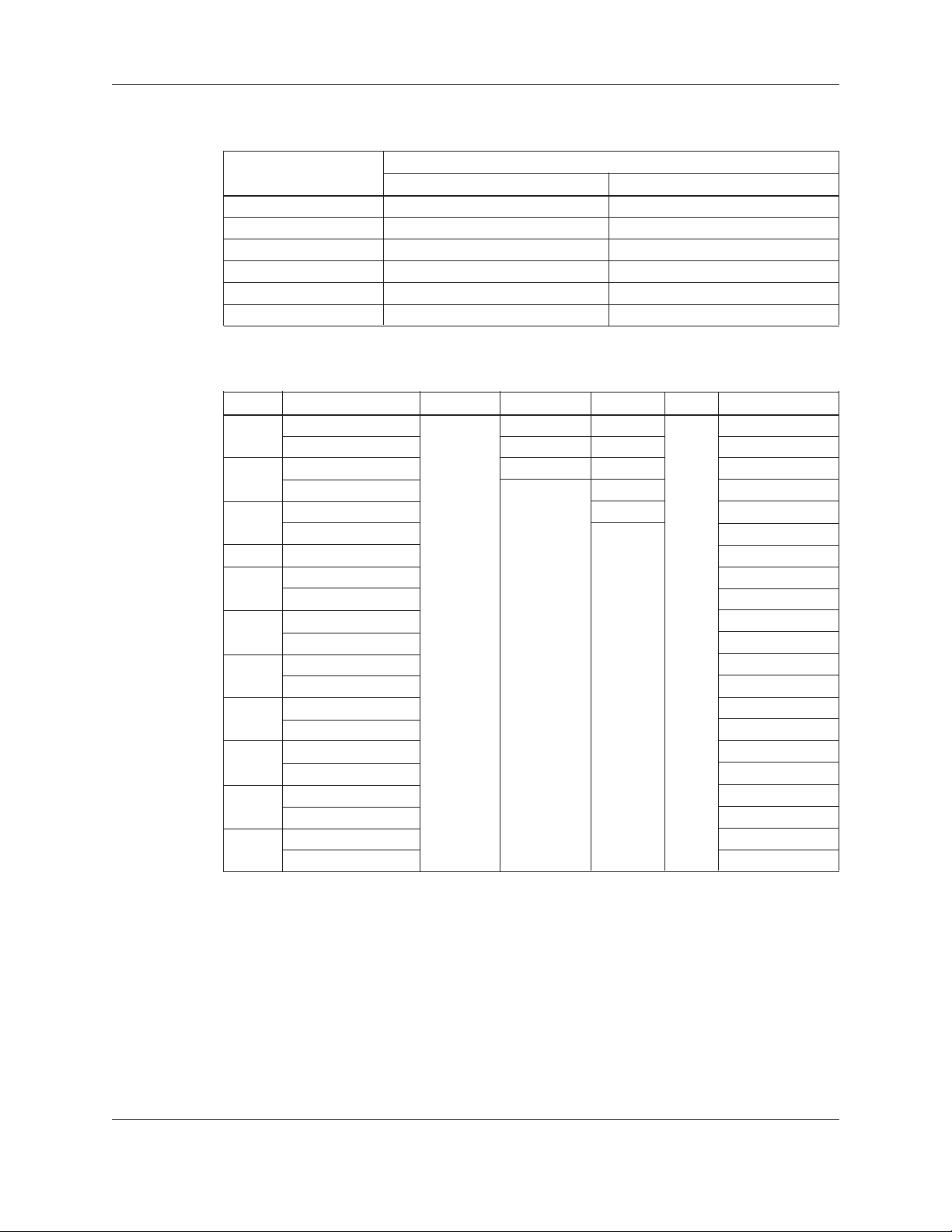
3. Disassemble the coupling (supplied with pump) by removing the (6) socket head screws
and machine washers between the coupling halves (see Figure 3). Retain bolts and dowel
pin for reassembly.
Figure 3: Motor Coupling
Item Quantity Description
A 2 Coupling Half
B 6 Socket Head Cap Screw
C 6 Lock-washer
D 1 Dowel Pin
4. Take care to make sure that the pump and motor shafts are clean; they should be free
of all burrs, oil, and grease. Both the pump and motor shafts should be completely dry
before moving on to the next step.
5. Install the dowel pin on the pump shaft and loosely assemble the shaft coupling. Do not
tighten the coupling at this point; it should be left loose enough to receive the motor
shaft in the following section.
6. Insert the impeller shim (supplied with the pump) between the shaft coupling and seal
gland. This will lift the shaft/impellers to the running position.
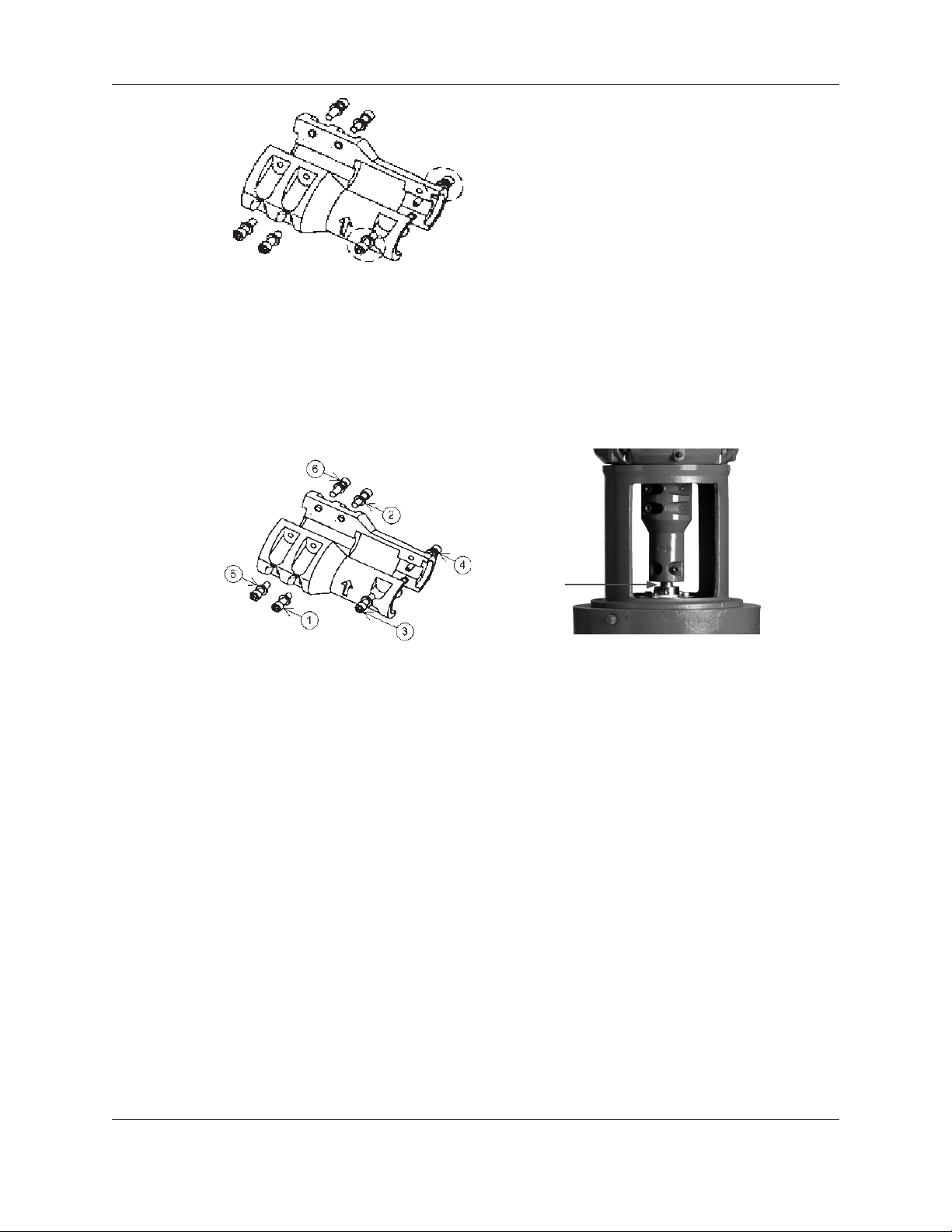
7. Very lightly tighten the (2) socket head cap screws on the pump end of the coupling (refer
to Figure 4). Tighten the coupling evenly; ensure that the coupling is symmetrical on both
the pump and motor shafts. Do NOT torque the cap screws in this step.
12 SMVT Installation, Operation and Maintenance Manual

Installation (continued)
Figure 4: Coupling Socket Head Screws
8. Very lightly tighten the remaining (4) socket head screws on the coupling. Tighten the
coupling evenly; ensure that the coupling is symmetrical on both the pump and motor
shafts. Do NOT torque the cap screws in this step.
9. Torque the socket head cap screws on the coupling. Refer to Figure 5 for the proper
torque pattern. See the “Engineering Data” section on page 8 of this manual for the
proper torque value.
Figure 5: Coupling Torque Pattern Figure 5a: Run Out Measurement Location
10. Remove the impeller shim and retain for future use.
11. Visually inspect the gaps between the coupling to ensure they are symmetrical on both
sides and consistent throughout the length of the coupling.
12. Inspect run out of the shaft between the bottom of the coupling and the mechanical seal
as shown in Figure 5a. If the run out exceeded 0.005”, the coupling must be adjusted. It
is usually most effective to adjust the four bolt section of the coupling.
13. Tighten the set screws on the seal gland. See the “Engineering Data” section on page 8 of
this manual for the proper torque value.
14. Install the (2) coupling guards.
Piping
General: Guidelines for piping are given in the “Hydraulic Institute Standards” and should
be reviewed prior to installation.
Warning: Never draw piping into place by using force on the suction and
discharge connections of the pump. This may impose dangerous strains on the
unit causing misalignment, poor operation and physical injury and damage to the
equipment.
1. All piping must be supported independently of and line up naturally with the pump suction
and discharge. It MUST NOT place piping loads on the pump.
2. Piping should be no smaller than the pump’s suction and discharge connections and kept as
short as possible, with minimal fittings to minimize friction losses.
SMVT Installation, Operation and Maintenance Manual 13

Installation (continued)
3. DO NOT connect piping to pump until pump and/or driver are securely fastened to a
supporting structure.
4. When pumping liquids at elevated temperatures, it is recommended that expansion loops or
joints be used in the suction and discharge piping. Refer to Figure 6 for correct placement
to avoid pump strain or misalignment due to linear expansion of piping.
Figure 6: Correct Placement of Expansion Joint
5. The piping should be arranged to permit pump isolation on both the suction and discharge
sides so that the pump can be drained during maintenance and repair.
6. Carefully clean all pipe parts, valves and ttings and pump branches prior to assembly.
7. All pipe joints MUST be airtight.
8. Proper placement of any temperature probes should be at the top end of the pump
Suction Piping
unit casing in one of the provided ports. Ports will come from factory plugged. Proper
temperature probe location is shown in Figure 7.
Figure 7: Correct Placement of Temperature Probes
Warning: NPSH available must always exceed NPSH required by the pump. For
suction lifts over 10 feet (3 meters) and liquid temperatures over 120°F (49°C),
consult the performance curve for your pump to determine NPSH required.
Properly installed suction piping is a necessity for trouble-free pump operation. Suction
piping should be ushed BEFORE connection to the pump.
1. Use of elbows close to pump suction should be avoided. There should be a minimum of two
pipe diameters of straight pipe between elbow and suction inlet (Reference Figure 8). All
elbows should be long-radius.
14 SMVT Installation, Operation and Maintenance Manual

Installation (continued)
Figure 8: Piping Elbows
2. Use suction pipe that is one or two sizes larger than the pump suction with a reducer at the
suction. Suction piping should never be smaller diameter than the pump suction.
3. Reducers should be eccentric at the pump suction with sloping side down and horizontal
side at the top (Reference Figure 9).
Figure 9: Eccentric Reducer
4. Suction strainers, when used, must have a net “free area” of at least three times the suction
pipe area.
5. Separate suction lines are recommended when more than one pump is operating from the
same source or supply.
Suction Lift Conditions
If pump is to be installed above the liquid source, the following MUST be provided:
1. No part of the suction piping can be above the pump suction (to avoid air pockets).
2. Suction piping must slope upwards to the pump on any horizontal pipe sections.
3. All joints MUST be airtight.
4. A means of maintaining prime during intermittent duty, such as a foot valve, must be
provided.
5. The suction strainer or suction bell MUST be at least three times the diameter of the
suction.
6. Ensure that the size and minimum submergence over the suction inlet is sufcient to prevent
air from entering the pump through a suction vortex. See typical intake piping arrangements
in Figures 10-13.
SMVT Installation, Operation and Maintenance Manual 15

Installation (continued)
H min.
D
Figure 10
3.0D
min.
1.5D
min.
H min.
D min.
D D
2
Figure 12
Figures 10-13: Typical Piping Arrangements
Suction Head (Flooded Suction) Conditions
If pump is to be installed below the liquid source, the following MUST be provided:
1. An isolation valve should be installed in the suction line at least two pipe diameters from the
pump suction to permit closing the line for pump maintenance.
H min.
H
16
15
14
13
12
11
10
H = Min. Submergence in feet
Figure 11
9
8
7
6
5
4
3
2
1
1234567891011 121314 1516
V = Velocity in feet per second
= GPM x 0.321
Area
GPM x 0.4085
Figure 13
D
V
2
D
2. Keep suction pipe free from air pockets.
3. Piping should be level or slope gradually downward from the source of supply.
4. No portion of the piping should extend below pump suction.
5. The size of the entrance from the supply should be one or two sizes larger than the suction
pipe.
6. The suction pipe must be adequately submerged below the liquid surface to prevent vortices
and air entrainment at the supply. See above illustrations.
Discharge Piping
1. Isolation and check valves should be installed in the discharge line. Locate the check valve
between the isolation valve and the pump. This will permit inspection of the check valve.
The isolation valve is required for priming, regulation of ow and for inspection and
maintenance of the pump. The check valve prevents pump or seal damage due to reverse
ow through the pump when the driver is off.
2. Increasers, if used, should be placed between the pump and check valves.
3. Cushioning devices should be used to protect the pump from surges and water hammer if
quick closing valves are installed in the system.
WARNING: Do not use the isolation/gate valve to throttle the pump as this
may cause loss of prime, excessive temperatures and damage to pump, voiding
warranty.
16 SMVT Installation, Operation and Maintenance Manual

Typical Plumbing and Installation
Installation (continued)
Figure 14: Typical Plumbing and Installation
Final Piping Check
After connecting the piping to the pump, rotate the motor shaft to make sure that there is
no binding.
Wiring
Warning: DISCONNECT AND LOCKOUT ELECTRICAL POWER BEFORE
WARNING
INSTALLING OR SERVICING PUMP.
Warning: Install ground and wire according to local and National Electrical
Code requirements.
Hazardous voltage
can shock, burn or
cause death.
Warning: Install an all leg electrical power disconnect switch near the pump.
Warning: Electrical supply MUST match motor’s nameplate specications.
Incorrect voltage can cause fire, damage the motor and void the warranty.
SMVT Installation, Operation and Maintenance Manual 17

Installation (continued)
WARNING
Hazardous machinery
can cause personal
injury or death.
Warning: Motors without built-in protection MUST be provided with contactors
and thermal overloads for single phase motors, or starters with heaters for three
phase motors. See motor nameplate.
Warning: Motors equipped with automatic thermal protectors open the motor’s
electrical circuit when an overload exists. This can cause the pump to start
unexpectedly and without warning.
• Use only stranded copper wire to motor and ground.
• Wire size MUST limit the maximum voltage drop to 10% of the motor nameplate voltage at
the motor terminals.
• The ground wire MUST be at least as large as the wire to the motor.
• Wires should be color coded for ease of maintenance.
• Follow motor manufacturer’s wiring diagram on the motor nameplate or terminal cover
carefully.
• Three phase motors require all-leg protection with properly sized magnetic starters and
thermal overloads.
Warning: Failure to permanently ground the pump, motor and controls before
connecting to electrical power can cause shock, burns or death.
Connect the electrical leads to the motor as follows:
Single Phase Motors
1. Connect the BLACK wire to the BLACK motor lead.
2. Connect the WHITE wire to the WHITE motor lead.
3. Connect the GREEN wire to the GREEN motor lead.
Three Phase Motors
See Figure 15 for three-phase wiring diagrams.
18 SMVT Installation, Operation and Maintenance Manual

208-230V 3/60 460V 3/60
Installation (continued)
Rotation
4
4
5
6
1
L
1
7
7
5
8
6
2
MOTOR LEADS
8
L
2
9
MOTOR LEADS
1
L
1
3
L
3
9
POWER CABLE LEADS
2
3
G
L
2
L
3
G
POWER CABLE LEADS
Figure 15: Three Phase Motor Wiring Diagram
Notice: Incorrect rotation may cause damage to the pump and voids the warranty.
• Correct rotation is left-hand, counter-clockwise when viewed from the motor end.
• Check rotation by observing the motor fan or the coupling THROUGH the coupling guard.
DO NOT confuse the rotation direction with the ow arrows cast into the pump body. The
rotation arrow is cast into the coupling.
• To reverse three phase motor rotation, have a qualied technician interchange any two of
the three power supply leads.
SMVT Installation, Operation and Maintenance Manual 19

Commissioning, Startup, Operation and Shutdown
V. Commissioning, Startup, Operation
and Shutdown
Overview
This section covers the basic procedures to use in preparing your pump for startup, starting,
operating and shutting it down. DO NOT CONTINUE UNTIL ALL PARTS OF THE
INSTALLATION PROCESS (SECTION IV) HAVE BEEN COMPLETED.
Priming
Never start the pump until it has been properly primed. Several different methods of
priming can be used, depending upon type of installation and service involved.
Warning: SMVT pumps are not self priming and must be fully primed at all
times during operation. Loss of prime can lead to excessive heat and severe
damage to the pump and seal.
Suction Lift (Liquid below Pump Suction):
1. Install a foot valve at suction end.
2. Remove the vent plug. See Figure 16.
3. With a vented funnel, completely fill the casing with liquid at the vent plug opening.
4. Re-install the vent plug.
5. Open the suction valve.
Flooded suction (Liquid above Pump Suction):
1. Close the discharge valve.
2. Remove the vent plug. See Figure 16.
Figure 16: Vent/Drain Plug Locations
3. Slowly open the suction valve until liquid ows out of the vent plug opening.
4. Re-install the vent plug.
5. Open the discharge valve.
20 SMVT Installation, Operation and Maintenance Manual

Precautions
Starting
Commissioning, Startup, Operation and Shutdown (continued)
Warning: Do not operate units without safety guards in place or severe personal
injury may result.
Warning: Splashing or immersing open drip proof motors in uid can cause re,
shock, burns or death. Make sure motor guards are in place.
1. Make sure suction valve and any recirculation or cooling lines are open.
2. Fully close or partially open discharge valve as dictated by system conditions.
3. Start driver.
WARNING
Hazardous machinery
can cause personal
injury or death.
Operation
Warning: DO NOT operate unit without safety guards in place. To do so could
result in severe personal injury or death.
Caution: Immediately observe pressure gauges. If discharge pressure is not
quickly attained, stop driver, re-prime and attempt to restart.
4. Slowly open discharge valve until the desired ow is obtained.
Caution: Observe pump for vibration levels, bearing temperature and excessive
noise. If normal levels are exceeded, shut down and resolve.
5. After stabilizing the system at normal operating conditions, check the piping and adjust
supports if needed.
General considerations:
Caution: Always vary capacity with regulating valve in the discharge line. Never
throttle ow from the suction side.
Caution: Driver may overload if the pumpage specic gravity (density) or
viscosity is greater than originally assumed or the rated ow rate is exceeded.
Caution: Always operate the pump at or near the rated conditions to prevent
damage resulting from cavitation or recirculation.
SMVT Installation, Operation and Maintenance Manual 21

Commissioning, Startup, Operation and Shutdown (continued)
Operating at reduced capacity:
WARNING
Warning: DO NOT operate pump below minimum rated ows or with suction
and or discharge valve closed. These conditions may create an explosive hazard
due to vaporization of pumpage and can quickly lead to pump failure, physical
injury or property damage.
Extreme heat can
cause personal injury
or property damage.
Caution: Damage can occur from:
1. Increased vibration levels – affects bearings and mechanical seal.
2. Increased radial loads – Stresses on shaft and bearings.
3. Heat build-up – Vaporization causing rotating parts to score or seize.
4. Cavitation – Damage to internal surfaces of pump.
Operating under Freezing Conditions
Exposure to freezing conditions while pump is idle could cause liquid to freeze and damage
the pump. Liquid inside the pump should be drained.
Shutdown
1. Slowly close the discharge valve.
2. Shut down and lock the driver to prevent accidental rotation.
Warning: When handling hazardous and or toxic uids, proper personal
protective equipment should be worn. If pump is being drained, precautions
must be taken to prevent physical injury. Pumpage must be handled and disposed
of in conformance with applicable environmental regulations.
22 SMVT Installation, Operation and Maintenance Manual

VI. Maintenance
Overview
This section covers the procedures, precautions and schedule for maintenance of your
Goulds Water Technology pump. A routine maintenance program can extend the life of
your pump. Well maintained equipment will last longer and require fewer repairs.
Warnings
Failure to disconnect and lockout electrical power before attempting any
maintenance can cause shock, burns or death.
Failure to relieve system pressure and drain system before attempting any
maintenance can cause property damage, personal injury or death.
If piping is hazardous or toxic fluids, system must be flushed prior to performing
service involving liquid end disassembly.
Maintenance Schedule
Inspection intervals should be shortened appropriately if the pumpage is abrasive or
corrosive, or if the environment is classified as potentially explosive.
Maintenance
Routine Maintenance
• Motor Maintenance
• Seal monitoring
• Vibration analysis
• Discharge pressure
• Temperature monitoring
Routine Inspections
• Check for unusual noise, vibration and bearing temperatures
• Inspect pump and piping for leaks
• Check static seal leakage
• Mechanical seal: should be no leakage
3 Month Inspections
• Check the foundation and hold-down bolts for tightness.
• If the pump has been left idle, check the seal and replace if needed.
Annual Inspections
• Check the pump capacity, pressure and power. If pump performance does not satisfy
your process requirements and the process requirements have not changed, the pump
should be disassembled; inspected and worn parts should be replaced. Otherwise, a
system inspection should be done.
Motor Maintenance
Consult the motor manufacturer’s Installation, Operation, and Maintenance manual
supplied with your motor for proper maintenance procedure and schedule.
SMVT Installation, Operation and Maintenance Manual 23

Maintenance (continued)
General Disassembly
Required Tools: The following tools should be available for use during pump disassembly
and assembly. Wrenches, lifting sling, rubber mallet, torque wrench with sockets, non-
corrosive cleaning agents, and impeller shim (supplied with pump).
Warning: Lock out power supply to driver motor to prevent accidental startup
and physical injury.
Warning: Pump components can be heavy. Proper methods of lifting must be
employed to avoid physical injury and/or equipment damage. Steel toed shoes
must be worn at all times.
Warning: The pump may handle hazardous and/or toxic uids. Proper personal
protective equipment should be worn. Precautions must be taken to prevent
physical injury. Pumpage must be handled and disposed of in conformance with
applicable environmental regulations.
Warning: Allow all system and pump components to cool before handling them
to prevent physical injury.
Note: Before disassembling the pump for overhaul, ensure all replacement parts
are available.
Mechanical Seal Replacement
Warning: Lock out power supply to driver motor to prevent accidental startup
and physical injury.
Warning: Pump components can be heavy. Proper methods of lifting must be
employed to avoid physical injury and/or equipment damage. Steel toed shoes
must be worn at all times.
Warning: The pump may handle hazardous and/or toxic uids. Proper personal
protective equipment should be worn. Precautions must be taken to prevent
physical injury. Pumpage must be handled and disposed of in conformance with
applicable environmental regulations.
Warning: Allow all system and pump components to cool before handling them
to prevent physical injury.
Note: Before disassembling the pump for overhaul, ensure all replacement parts
are available.
1. Close all necessary suction and discharge valves.
2. Drain the liquid from the pump by removing the lower drain plugs and the upper vent plug.
See Figure 17.
24 SMVT Installation, Operation and Maintenance Manual

Maintenance (continued)
Figure 17: Vent/Drain Plug Locations
3. Remove the (2) coupling guards.
4. Disassemble the coupling by removing the (6) socket head screws. Remove the dowel pin
on the pump shaft. See Figure 18. Retain bolts and dowel pin for reassembly.
Figure 18: Motor Coupling
Item Quantity Description
A 2 Coupling Half
B 6 Socket Head Cap Screw
C 6 Lock-washer
D 1 Dowel Pin
5. Loosen the set screws on the seal collar.
6. Remove the (4) hex head cap screws on the seal gland. Retain bolts for reassembly.
7. Carefully lift the entire seal assembly from the seal housing by sliding it up the pump
shaft. Discard the entire seal assembly.
8. Lubricate the inside of the mechanical seal assembly (supplied with pump) with grease
(such as Armored AutoGroup “STP” or Dow Corning “111 Grease”) or a mixture of
equal parts non-petroleum hand soap and water. Be sure that there is an o-ring at the
back of the gland ange.
9. Take care to make sure that the pump shaft is clean; it should be free of all burrs, oil, and
grease. The pump shaft should be completely dry before moving on to the next step.
10. To install the new mechanical seal assembly, carefully slide it down the pump shaft until
the gland contacts the mounting surface on the top of the seal housing.
SMVT Installation, Operation and Maintenance Manual 25

Maintenance (continued)
11. Install the (4) hex cap screws on the seal gland to the seal housing. See the “Engineering
Data” section on page 8 of this manual for the proper torque value.
12. Take care to make sure that the pump and motor shafts are clean; they should be free
of all burrs, oil, and grease. Both the pump and motor shafts should be completely dry
before moving on to the next step.
13. Install the dowel pin on the pump shaft and loosely assemble the shaft coupling. Do
not tighten the coupling at this point; it should be left loose enough to set the running
position in the next step.
14. Insert the impeller shim (supplied with the pump) between the shaft coupling and seal
gland. This will lift the shaft/impellers to the running position.
15. Very lightly tighten the (2) socket head cap screws on the pump end of the coupling (refer
to Figure 19). Tighten the coupling evenly; ensure that the coupling is symmetrical on
both the pump and motor shafts. Do NOT torque the cap screws in this step.
Figure 19: Coupling Socket Head Screws
16. Very lightly tighten the remaining (4) socket head screws on the coupling. Tighten the
coupling evenly; ensure that the coupling is symmetrical on both the pump and motor
shafts. Do NOT torque the cap screws in this step.
17. Torque the socket head cap screws on the coupling. Refer to Figure 20 for the proper
torque pattern. See the “Engineering Data” section on page 8 of this manual for the
proper torque value.
Figure 20: Coupling Torque Pattern Figure 20a: Run Out Measurement Location
18. Remove the impeller position shim. Retain for later use.
19. Visually inspect the gaps between the coupling to ensure they are symmetrical on both
sides and consistent throughout the length of the coupling.
20. Inspect run out of the shaft between the bottom of the coupling and the mechanical seal
as shown in Figure 20a. If the run out exceeded 0.005”, the coupling must be adjusted.
It is usually most effective to adjust the four bolt section of the coupling.
26 SMVT Installation, Operation and Maintenance Manual

21. Tighten the set screws on the seal gland. See the “Engineering Data” section on page 8 of
this manual for the proper torque value.
22. Install the (2) coupling guards.
23. Follow the instructions in “Section V. Commissioning, Startup, Operation, and
Shutdown” for the proper procedures to restart the pump.
Motor Replacement
1. Remove the (2) coupling guards.
2. Loosen the set screws on the seal gland.
3. Disassemble the coupling by removing the (6) socket head screws. Remove the dowel pin
on the pump shaft. See Figure 21. Retain bolts and dowel pin for reassembly.
Maintenance (continued)
Figure 21: Motor Coupling
Item Quantity Description
A 2 Coupling Half
B 6 Socket Head Cap Screw
C 6 Lock-washer
D 1 Dowel Pin
4. Remove the (4) hex head bolts the join the motor and motor adapter. Retain bolts for
reassembly.
5. With an adequately sized crane carefully remove the motor assembly.
6. With an adequately sized crane carefully lower the new motor assembly onto the motor
adapter located on the top of the pump.
7. Secure the motor with the (4) hex head bolts. See the “Engineering Data” section on page
8 of this manual for the proper torque value.
8. Take care to make sure that the pump and motor shafts are clean; they should be free
of all burrs, oil, and grease. Both the pump and motor shafts should be completely dry
before moving on to the next step.
9. Install the dowel pin on the pump shaft and loosely assemble the shaft coupling. Do not
tighten the coupling at this point; it should be left loose enough to receive the motor
shaft in the following section.
10. Insert the impeller shim (supplied with the pump) between the shaft coupling and seal
gland. This will lift the shaft/impellers to the running position.
11. Very lightly tighten the (2) socket head cap screws on the pump end of the coupling (refer
to Figure 22). Tighten the coupling evenly; ensure that the coupling is symmetrical on
both the pump and motor shafts. Do NOT torque the cap screws in this step.
SMVT Installation, Operation and Maintenance Manual 27
Maintenance (continued)
Figure 22: Coupling Socket Head Screws
12. Very lightly tighten the remaining (4) socket head screws on the coupling. Tighten the
coupling evenly; ensure that the coupling is symmetrical on both the pump and motor
shafts. Do NOT torque the cap screws in this step.
13. Torque the socket head cap screws on the coupling. Refer to Figure 23 for the proper
torque pattern. See the “Engineering Data” section on page 8 of this manual for the
proper torque value.
Figure 23: Coupling Torque Pattern Figure 23a: Run Out Measurement Location
14. Remove the impeller shim and retain for future use.
15. Visually inspect the gaps between the coupling to ensure they are symmetrical on both
sides and consistent throughout the length of the coupling.
16. Inspect run out of the shaft between the bottom of the coupling and the mechanical seal
as shown in Figure 23a. If the run out exceeded 0.005”, the coupling must be adjusted.
It is usually most effective to adjust the four bolt section of the coupling.
17. Tighten the set screws on the seal gland. See the “Engineering Data” section on page 8 of
this manual for the proper torque value.
18. Install the (2) coupling guards.
19. Follow the instructions in “Section IV. Installation” to properly wire the motor.
20. Follow the instructions in “Section V. Commissioning, Startup, Operation, and
Shutdown” for the proper procedures to restart the pump.
28 SMVT Installation, Operation and Maintenance Manual

Pump Disassembly Instructions and Internal Stack Replacement
Warning: Lock out power supply to driver motor to prevent accidental startup
and physical injury.
Warning: Pump components can be heavy. Proper methods of lifting must be
employed to avoid physical injury and/or equipment damage. Steel toed shoes
must be worn at all times.
Warning: The pump may handle hazardous and/or toxic uids. Proper personal
protective equipment should be worn. Precautions must be taken to prevent
physical injury. Pumpage must be handled and disposed of in conformance with
applicable environmental regulations.
Warning: Allow all system and pump components to cool before handling them
to prevent physical injury.
Note: Before disassembling the pump for overhaul, ensure all replacement parts
are available.
1. Close all necessary suction and discharge valves.
Maintenance (continued)
2. Drain the liquid from the pump by removing the lower drain plugs and the upper vent
plug. See Figure 24.
Figure 24: Vent/Drain Plug Locations
3. Remove the (2) coupling guards.
4. Loosen the set screws on the seal collar.
5. Disassemble the coupling by removing the (6) socket head screws. Remove the dowel pin
on the pump shaft. See Figure 25. Retain bolts and dowel pin for reassembly.
Figure 25: Motor Coupling
SMVT Installation, Operation and Maintenance Manual 29

Maintenance (continued)
Item Quantity Description
A 2 Coupling Half
B 6 Socket Head Cap Screw
C 6 Lock-washer
D 1 Dowel Pin
6. Remove the (4) hex head bolts the join the motor and motor adapter. Retain bolts for
reassembly.
7. With an adequately sized crane carefully remove the motor assembly.
8. Remove the (4) hex head bolts on the seal gland. Retain bolts for reassembly.
9. Carefully lift the entire seal assembly from the seal housing by sliding it up the pump
shaft. Retain the seal assembly for pump reassembly.
10. Remove the (12) upper casing bolts. See Figure 26. Retain bolts for reassembly.
UPPER CASING
BOLTS
(TYP 12 PLCS)
Figure 26: Upper Casing Bolts
11. With an adequately sized crane carefully lift the internal stack from the pump casing.
Lift from the motor adapter as shown on page 7 of this manual. The motor adapter, seal
plate, pump shaft, and cartridge stack will lift as a complete unit.
12. Carefully set the cartridge stack removed from the pump so that the stack is supported
and the seal plate is accessible.
13. Remove the (6) bowl bolts that connect the upper bowl of the cartridge stack to the seal
plate. The seal plate and motor adapter can be removed as a single unit. Retain bolts for
reassembly.
14. Assemble the seal plate/motor adapter to the replacement cartridge stack using the (6)
bowl bolts removed in step 13. Torque the bolts in the pattern shown in Figure 27. See
the “Engineering Data” section on page 8 of this manual for the proper torque value.
Figure 27: Bowl Bolts Torque Pattern
30 SMVT Installation, Operation and Maintenance Manual

Maintenance (continued)
15. Install a new o-ring on the lower suction cover of the replacement cartridge stack.
16. Remove the old o-ring on the upper ange of the pump casing and discard. Install a new
o-ring on the upper ange of the pump casing.
17. With an adequately sized crane carefully lift the replacement stack. Lift from the motor
adapter as shown on page 7 of this manual. The motor adapter, seal plate, pump shaft,
and cartridge stack will lift as a complete unit.
18. Carefully lower the replacement stack approximately halfway into the pump casing. Align
the motor adapter windows to the desired orientation.
19. VERY slowly and carefully continue to lower the replacement stack into the pump casing.
As the seal plate approaches the upper ange of the pump casing, take care to align the
bolt circles of the pump casing and seal plate.
20. Smoothly guide the replacement stack so that the lower suction cover engages the
pump body. Be careful to avoid damaging the lower o-ring, as this will affect the pump
performance.
21. Install the (12) upper casing bolts ‘nger-tight’.
22. Torque the (12) upper casing bolts in the pattern shown in Figure 28. See the
“Engineering Data” section on page 8 of this manual for the proper torque value.
Figure 28: Upper Casing Bolts Torque Pattern
23. Lubricate the inside of the mechanical seal assembly (supplied with pump) with grease
(such as Armored AutoGroup “STP” or Dow Corning “111 Grease”) or a mixture of
equal parts non-petroleum hand soap and water. Be sure that there is an o-ring at the
back of the gland ange.
24. Take care to make sure that the pump shaft is clean; it should be free of all burrs, oil, and
grease. Pump shaft should be completely dry before moving on to the next step.
25. To install the mechanical seal assembly, carefully slide it down the pump shaft until the
gland contacts the mounting surface on the top of the seal housing.
26. Install the (4) hex cap screws on the seal gland to the seal housing. See the “Engineering
Data” section on page 8 of this manual for the proper torque value.
27. With an adequately sized crane carefully lower the motor assembly onto the motor
adapter located on the top of the pump. Allow the motor shaft to engage into the
coupling. Be careful not to damage the motor shaft.
28. Secure the motor to the motor adapter with the (4) hex head bolts removed in step 6 of
this section. See the “Engineering Data” section on page 8 of this manual for the proper
torque value.
29. Take care to make sure that the pump and motor shafts are clean; they should be free
of all burrs, oil, and grease. Both the pump and motor shafts should be completely dry
before moving on to the next step.
SMVT Installation, Operation and Maintenance Manual 31

Maintenance (continued)
30. Install the dowel pin on the pump shaft and loosely assemble the shaft coupling. Do not
tighten the coupling at this point; it should be left loose enough to receive the motor
shaft in the following section.
31. Insert the impeller shim (supplied with the pump) between the shaft coupling and seal
gland. This will lift the shaft/impellers to the running position.
32. Very lightly tighten the (2) socket head cap screws on the pump end of the coupling (refer
to Figure 29). Tighten the coupling evenly; ensure that the coupling is symmetrical on
both the pump and motor shafts. Do NOT torque the cap screws in this step.
Figure 29: Coupling Socket Head Screws
33. Very lightly tighten the remaining (4) socket head screws on the coupling. Tighten the
coupling evenly; ensure that the coupling is symmetrical on both the pump and motor
shafts. Do NOT torque the cap screws in this step.
34. Torque the socket head cap screws on the coupling. Refer to Figure 30 for the proper
torque pattern. See the “Engineering Data” section on page 8 of this manual for the
proper torque value.
Figure 30: Coupling Torque Pattern Figure 30a: Run Out Measurement Location
35. Remove the impeller shim and retain for future use.
36. Visually inspect the gaps between the coupling to ensure they are symmetrical on both
sides and consistent throughout the length of the coupling.
37. Inspect run out of the shaft between the bottom of the coupling and the mechanical seal
as shown in Figure 30a. If the run out exceeded 0.005”, the coupling must be adjusted. It
is usually most effective to adjust the four bolt section of the coupling.
38. Tighten the set screws on the seal gland. See the “Engineering Data” section on page 8 of
this manual for the proper torque value.
39. Install the (2) coupling guards.
32 SMVT Installation, Operation and Maintenance Manual

40. Follow the instructions in “Section IV. Installation” to properly wire the motor.
41. Follow the instructions in “Section V. Commissioning, Startup, Operation, and
Shutdown” for the proper procedures to restart the pump.
VII. Troubleshooting
Failure to disconnect and lockout electrical power before attempting any maintenance
can cause shock, burns or death.
Symptoms
MOTOR NOT RUNNING
(See Probable Causes 1 through 5)
LITTLE OR NO LIQUID BEING DELIVERED BY PUMP
(See Probable Causes 6 through 12)
POWER CONSUMPTION TOO HIGH
(See Probable Causes 3, 12, 13, 15)
EXCESSIVE NOISE AND VIBRATION
(See Probable Causes 3, 6-8, 10, 12, 13, 16 )
Troubleshooting
PROBABLE CAUSE
1. Motor thermal protector tripped.
2. Open circuit breaker or blown fuse.
3. Impellers binding.
4. Motor improperly wired.
5. Defective Motor.
6. Pump is not primed, air or gas in liquid.
7. Discharge or suction plugged, or valve closed.
8. Incorrect rotation (three-phase only)
9. Low voltage or phase loss.
10. Impellers worn or plugged.
11. System head too high.
12. NPSHa too low-excessive suction lift or losses.
13. Discharge head too low-excessive ow rate.
14. Fluid viscosity, specific gravity too high.
15. Worn bearing.
16. Pump, motor or piping loose.
SMVT Installation, Operation and Maintenance Manual 33

Appendix
VIII. Appendix
SMVT Product Line Numbering System
The various versions of the SMVT line are identified by a product code number on the pump label.
This number is also the catalog number for the pump. The meaning of each digit in the product
code number is shown below. Note: Not all combinations are possible. Consult your Goulds Water
Technology distributor.
Example Product Code: SM3A1J2C1VA
BEP
Flow
Product 60 Hz
Line (50 Hz) Material Hz/RPM HP Driver Stages Seal Options Trim
A Trim B Trim C Trim
D Trim E Special Trim
V = Vertical Mount
H = Horizontal Mount
1 = Standard 2B Crane Seal
A = 1, B = 2, C = 3, D = 4,
E = 5, F = 6, G = 7, H = 8,
J = 9, K = 10, L = 11, M = 12
1 = 1 PH ODP,
2 = 3 PH ODP,
3 = 3 PH 575 V ODP,
4 = 1 PH TEFC,
5 = 3 PH TEFC,
6 = 3 PH 575 V TEFC,
7 = 3 PH 415 V ODP,
8 = 3 PH 415 V TEFC
A = 3 HP, B = 5 HP, C = 7.5 HP,
D = 10 HP, E = 15 HP, F = 20 HP,
G = 25 HP, H = 30 HP, J = 40 HP,
K = 50 HP, L = 60 HP, M = 75 HP
1 = 60 Hz, 3600 RPM;
2 = 50 Hz, 3000 RPM
A = Standard construction
with carbon steel casing
D = Standard construction
with stainless steel casing
1 = 175 GPM (33 m3/hr),
2 = 230 GPM (45 m3/hr),
3 = 380 GPM (72 m3/hr),
4 = 480 GPM (91 m3/hr),
5 = 600 GPM (114 m3/hr),
6 = 700 GPM (133 m3/hr)
SM = SMVT
34 SMVT Installation, Operation and Maintenance Manual

Sectional Pump Assembly
Appendix (continued)
Item No. Description
1 Pump Body
1B Pipe Plug – Drain
2 Suction Cover
2A O-Ring – Suction Cover
3 Intermediate Bowl
3A Hex Screws – Bowl
4 Bearing
5 Impeller
6 Taperlock
7 Shaft
8 Casing
8A O-Ring – Casing
8B Hex Screws – Casing
9 Motor Support
9A Guard – Motor Support
9B Pipe Plug
Motor Support
Hex Screws –
9C
10 Mechanical Seal
10A Hex Screws – Seal
11 Coupling
11A Cap Screws – Coupling
11B Lock Washers – Coupling
11C Dowel Pin – Coupling
12 Motor
12A Hex Screws – Motor
13 Seal Plate
SMVT Installation, Operation and Maintenance Manual 35

Notes
Notes
36 SMVT Installation, Operation and Maintenance Manual

Notes
Notes
SMVT Installation, Operation and Maintenance Manual 37

WARRANTY
WARRANTY – Company warrants title to the product(s) and, except as noted with respect to items not of Company’s manufacturer,
also warrants the product(s) on date of shipment to Purchaser, to be of the kind and quality described herein, and free of defects
in workmanship and material. THIS WARRANTY IS EXPRESSLY IN LIEU OF ALL OTHER WARRANTIES, INCLUDING
BUT NOT LIMITED TO IMPLIED WARRANTIES OF MERCHANT-ABILITY AND FITNESS, AND CONSTITUTES THE
ONLY WARRANTY OF COMPANY WITH RESPECT TO THE PRODUCT(S).
If within one year from date of initial operation, but not more than 18 months from date of shipment by Company of any
item of product(s), Purchaser discovers that such item was not as warranted above and promptly noties Company in writing
thereof, Company shall remedy such nonconformance by, at Company’s option, adjustment or repair or replacement of the
item and any affected part of the product(s). Purchaser shall assume all responsibility and expense for removal, reinstallation,
and freight in connection with the foregoing remedies. The same obligations and conditions shall extend to replacement parts
furnished by Company hereunder. Company shall have the right of disposal of parts replaced by it. Purchaser agrees to notify
Company, in writing, of any apparent defects in design, material or workmanship, prior to performing any corrective action
back-chargeable to the Company. Purchaser shall provide a detailed estimate for approval by the Company.
ANY SEPARATE LISTED ITEM OF THE PRODUCT(S) WHICH IS NOT MANUFACTURED BY THE COMPANY IS NOT
WARRANTED BY COMPANY and shall be covered only by the express warranty, if any, of the manufacturer thereof.
THIS STATES THE PURCHASER’S EXCLUSIVE REMEDY AGAINST THE COMPANY AND ITS SUPPLIERS RELATING
TO THE PRODUCT(S), WHETHER IN CONTRACT OR IN TORT OR UNDER ANY OTHER LEGAL THEORY, AND
WHETHER ARISING OUT OF WARRANTIES, REPRESENTATIONS, INSTRUCTIONS, INSTALLATIONS OR DEFECTS
FROM ANY CAUSE.
Company and its suppliers shall have no obligation as to any products which has been improperly stored or handled, or which
has not been operated or maintained according to instructions in Company or supplier furnished manuals.
Xylem, Inc.
P.O. Box 5487
Lubbock, TX 79408
Phone: (806) 763-7867
Fax: (800) 453-4749
www.xyleminc.com/brands/gouldswatertechnology
Goulds is a registered trademark of Goulds Pumps, Inc. and is used under license.
© 2012 Xylem, Inc. IM158 Revision Number 4 October 2012
 Loading...