

INSTRUCTION MANUAL
IMVICR01
MODEL VIC
VERTICAL INDUSTRIAL TURBINE CAN PUMPS
INSTALLATION, OPERATION AND MAINTENANCE INSTRUCTIONS

Foreword
Foreword
This manual provides instructions for the Installation, Operation, and Maintenance of the Goulds Water
Technology Vertical Industrial Turbine Type Can Pumps. This manual covers a standard product. For special
options, supplemental instructions are available. This manual must be read and understood before
installation and start-up.
This instruction manual covers several different pump models. Most assembly, disassembly, and inspection
procedures are the same for all the pumps. However, where there are differences, these differences will be noted
within the manual. The design, materials, and workmanship incorporated in the construction of the Goulds
Water Technology VIC pumps makes them capable of giving long, trouble-free service. The life and satisfactory
service of any mechanical unit, however, is enhanced and extended by correct application, proper installation,
periodic inspection, condition monitoring and careful maintenance. This instruction manual was prepared
to assist operators in understanding the construction and the correct methods of installing, operating, and
maintaining these pumps.
The information contained in this book is intended to assist operating personnel by providing information on the
characteristics of the purchased equipment. It does not relieve the user of their responsibility of using accepted
engineering practices in the installation, operation, and maintenance of this equipment.
Goulds Water Technology pumps shall not be liable for physical injury, damage, or delays caused by failure
to observe the instructions for installation, operation, and maintenance contained in this manual.
Warranty is valid only when genuine Goulds Water Technology pumps parts are used.
Use of the equipment on a service other than stated in the order will nullify the warranty, unless written approval
is obtained in advance from Goulds Pumps.
For information or questions not covered in this manual, contact Goulds Water Technology at (806) 743-5700.
THIS MANUAL EXPLAINS :
• Proper Installation • Pump Overhaul
• Start-up Procedures • Trouble Shooting
• Operation Procedures • Ordering Spare or Repair Parts
• Routine Maintenance
Owner’s Information
Pump Model Number:
Pump Serial Number:
Motor Model Number:
Motor Serial Number:
Dealer:
Dealer Telephone:
Purchase Date:
Installation Date:
2

Table of Contents
SUBJECT PAGE
SECTION 1 – Safety ................................................................................................................................................... 4
SECTION 2 – General Information ............................................................................................................................. 4
Introduction .............................................................................................................................................................. 4
Receiving and Checking ............................................................................................................................................4
Materials and Equipment Required ...........................................................................................................................5
Storage ...................................................................................................................................................................... 5
General Description .................................................................................................................................................. 6
SECTION 3 – Installation ........................................................................................................................................... 9
Foundation / Piping ................................................................................................................................................... 9
Pump Installation .................................................................................................................................................... 10
Installing the Bowl Assembly ................................................................................................................................... 10
Installing the Column .............................................................................................................................................. 11
Installing the Discharge Head .................................................................................................................................. 12
Installing the Stuffing Box .......................................................................................................................................12
Installing the Mechanical Seal .................................................................................................................................. 13
Mechanical Seal Alignment ...................................................................................................................................... 14
Installing the Driver ................................................................................................................................................ 14
Installing the Thrust Pot ..........................................................................................................................................19
SECTION 4 – Pump Start Up and Operation ............................................................................................................ 21
SECTION 5 – Maintenance ...................................................................................................................................... 22
Preventive Maintenance Schedule ............................................................................................................................ 22
Packing Adjustment and Replacement ...................................................................................................................... 22
Thrust Pot Lubrication and Maintenance ................................................................................................................. 23
Seasonal Shutdown .................................................................................................................................................. 23
Recommended Lubricants .......................................................................................................................................24
Troubleshooting ...................................................................................................................................................... 25
SECTION 6 – Disassembly and Reassembly ..............................................................................................................27
Disassembly ............................................................................................................................................................. 27
Inspection and Reassembly ...................................................................................................................................... 28
SECTION 7 – Repair Parts ........................................................................................................................................ 30
Limited Warranty ...................................................................................................................................................... 32
3
DANGER
WARNING
CAUTION
WARNING
Hazardous voltage
can shock, burn or
cause death.
WARNING
CAUTION
WARNING
CAUTION
Safety Instructions – SECTION 1
TO AVOID SERIOUS OR FATAL PERSONAL INJURY
OR MAJOR PROPERTY DAMAGE, READ AND
FOLLOW ALL SAFETY INSTRUCTIONS IN THE
MANUAL AND ON THE PUMP.
This is a SAFETY ALERT SYMBOL.
When you see this symbol on the pump or
in the manual, look for one of the following signal words and be alert to the potential for personal injury or property damage.
Warns of hazards that WILL cause serious
personal injury, death or major property
damage.
Warns of hazards that CAN cause serious
personal injury, death or major property
damage.
Warns of hazards that CAN cause personal
injury or property damage.
If equipment is to be installed in a potentially explosive atmosphere and these procedures are not
followed, personal injury or equipment damage
from an explosion may result.
NOTICE: INDICATES SPECIAL INSTRUCTIONS
WHICH ARE VERY IMPORTANT AND MUST BE
FOLLOWED.
THIS MANUAL IS INTENDED TO ASSIST IN
THE INSTALLATION AND OPERATION OF
THIS UNIT. THOROUGHLY REVIEW ALL
INSTRUCTIONS AND WARNINGS PRIOR TO
PERFORMING ANY WORK ON THIS PUMP.
MAINTAIN ALL SAFETY DECALS.
Install, ground and wire according
to local and National Electrical Code
Requirements.
Install an all leg disconnect switch
near the pump.
Disconnect and lockout electrical
power before installing or servicing
the pump.
Electrical supply must match motor’s
nameplate specifications. Incorrect
voltage can cause fire, damage motor
and void the warranty.
Single phase pump motors are equipped with an
automatic thermal protector, which opens the motor’s
electrical circuit when an overload condition exists.
This can cause the pump to start unexpectedly.
General Precautions
Personal injuries will result if procedures
outlined in this manual are not followed
Electric supply MUST match pump’s
nameplate specifications. Incorrect voltage
can cause fire, damage to motor and voids warranty.
Safety Apparel:
• Insulated work gloves when handling hot sand collar.
• Heavy work gloves when handling parts with sharp
4
edges, especially impellers.
• Safety glasses (with side shields) for eye protection.
• Steel-toed shoes for foot protection when handling
parts, heavy tools, etc.
• Other personal protective equipment to protect against
hazardous/toxic fluid.
Maintenance Safety:
• Always lock out power prior to any procedure.
• Ensure pump is isolated from system and the pressure
is relieved before disassembling the pump, removing
plugs, or disconnecting the piping.
• Use proper lifting and supporting equipment to prevent
serious injury or death.
• Observe all decontamination procedures.
General Information – SECTION 2
INTRODUCTION
NOTE: The information in this manual intends to be
used as a guide only. If you are in doubt, consult
your Goulds Water Technology representative
for specific information about your pump.
The design, material, and workmanship incorporated
in the construction of Goulds Water Technology VIC
pumps makes them capable of giving long, trouble
free service. The life and satisfactory service of any
mechanical unit, however, is enhanced and extended
by correct application, proper installation, periodic
inspection and careful maintenance. This instruction
manual was prepared to assist operators in understanding
the construction and the correct methods of installing,
operating and maintaining these pumps.
Rotating components of the pump
assembly must be covered with a suitable
rigid guard to prevent injury to personnel.
Improper impeller adjustment could cause
contact between the rotating and stationary
parts, resulting in a spark and heat generation.
Study thoroughly Sections 1 through 6 and carefully
follow the instructions for installing and operating.
Section 5 contains answers to troubleshooting and
maintenance questions. Keep this instruction manual
handy for reference.
Goulds Water Technology will not be
liable for any damages or delay caused by
failure to comply with the provisions of this instruction
manual.
RECEIVING AND CHECKING
The pump should be carefully supported prior to
unloading from the carrier. Handle all components
carefully. Inspection for damage of the shipping crate
should be made prior to unpacking the pump. After
unpacking, visually inspect the pump and check the
following:
1. Contents of the pump assembly against the
packing list.
2. All components against damage.

3. All shafting for damage, should the crate be
broken or show careless handling. All shafting
must be checked for straightness.
Any shortages or damages should be immediately called
to the attention of the local freight agent of the carrier by
which the shipment arrived and proper notation made on
the bill. This will prevent any controversy when a claim is
made and facilitate prompt and satisfactory adjustment.
MATERIALS AND EQUIPMENT REQUIRED
The material and equipment necessary for installation
of the pump will vary with the size of the pump and the
type of installation.
The following list of standard tools and supplies is
offered only as a guide.
BULK MATERIAL
• Anti-Galling lubricant
(such as Dow Corning “MOLYKOTE”)
• Thread Compound
• Lubrication Oil
• Turbine Oil
• Grease
RIGGING EQUIPMENT
• Mobile power hoist, traveling crane or derrick.
• Drag line and blocks.
• Lifting Bail for Threaded Column.
• Elevator clamps, if unit is unassembled.
• Clevises – for use with eyebolts.
• Timbers – size, length and quantity to support long
pump parts on the floor.
• I-Beams or timbers to support pump over
installation.
HAND TOOLS
• Pipe wrenches
• Feeler gauges
• Machinist Level
• Set of mechanics tools including: files, wire brush,
pliers, wire cutters and pocket knife.
• Clean rags
• Dial indicator to assist in motor and pump
alignment.
OPTIONAL TOOLS TO FACILITATE PUMP
ASSEMBLY AND DISASSEMBLY
• Taperlock driver to assist in bowl assembly and
disassembly for pumps with taper lock impellers
only.
STORAGE
Goulds Water Technology carefully preserves and
protects its products for shipment. However, the
effective life of the preservatives applied at the factory
can vary from 3 to 18 months depending on the severity
of the environment in which the equipment is stored.
This section provides procedures for preparation prior to
storage and maintenance during storage of Goulds Water
Technology pumps. These procedures are necessary
to protect the precision parts of the pumps. Specific
procedures for storing motors, gear-drivers, and engines,
should be obtained from the equipment manufacturer.
This section is intended to be of general assistance to
users of Goulds Water Technology VIC pumps. It shall
not modify, amend and/or otherwise alter the scope
of Goulds Water Technology VIC pumps warranty
responsibilities to the purchaser in any way whatsoever.
Storage Preparation
Goulds Water Technology VIC pumps require proper
preparation for storage and, regular maintenance during
storage. The pump shall be considered in storage when
it has been delivered to the job site and is awaiting
installation.
Preferably, the storage area shall be paved, well drained
and free from flooding, and be indoors whenever
possible.
Weatherproof coverings used for outdoor storage shall be
flame resistant type sheeting or tarpaulins. They shall be
placed so as to provide good drainage and air circulation
and shall be tied down to protect from wind damage.
Storage area shall be maintained in a clean condition at
all times.
Pumps and/or component parts shall be placed on skids,
pallets, or shoring to permit good air circulation.
Pumps and/or component parts shall be sorted so as to
permit ready access for inspection and/or maintenance
without excessive handling.
Pumps and/or component parts stacked during storage
shall be arranged so that the racks, containers, or crates
bear full weight without distortion of pumps or parts.
Identification markings must be readily visible. Any
cover removed for internal access shall be replaced
immediately.
Pump and bowl assembly shafting shall be rotated
counter clockwise, as a minimum, once a month. Shaft
shall not be left in the same previous position, nor in the
extreme raised or lowered lateral position. Shaft should
rotate freely.
NOTE: For further information on these procedures
contact your Goulds Water Technology
representative.
Recommended Storage Procedures
Controlled storage facilities should be maintained at an
even temperature 10º F (6º C) or more above the dew
point with relative humidity less than 50% and little or
no dust. (If these requirements can not be met the pump
is to be considered in uncontrolled storage.)
For uncontrolled storage periods of 6 months or less,
the pump is to be inspected periodically to insure that all
preservatives are intact.
All pipe threads and flanged pipe covers are to be sealed
with tape.
The pump must not be stored closer than six inches (15
cm) from the ground.
5

Uncontrolled Long Term Storage Preparations
When applicable to the pump, storage periods over six
months require the preceding storage procedure and
storage preparation plus the following:
Inspect the lube oil and seal flush piping and either
fill the piping with rust preventative oil, or re-coat the
piping periodically to prevent corrosion.
Place 10 pounds (4.5 kg) of moisture absorbing desiccant
or 5 pounds (2.3 kg) of vapor phase inhibitor crystals
near the center of the pump. If the pump is assembled,
place an additional one pound (0.5 kg) in the discharge
nozzle securely fastened to the discharge elbow.
Install a moisture indicator near the perimeter of the
pump. Cover the pump with 6 mil (0.15 mm) minimum
thickness black polyethylene or equal and seal it with
tape. Provide a small ventilation hole approximately ½
inch (12 mm) diameter.
Discharge Head
The discharge head is either a cast iron head or a
fabricated head. Ports are provided for connecting
the pressure gauge, stuffing box or mechanical seal
bypass return and lubricator connections. The driver
support portion of the discharge head is designed with
large windows for easy stuffing box or mechanical seal
adjustment. The windows are covered with coupling
guards for safe operation.
Column
Threaded or flanged column construction provides
positive shaft and bearing alignment and ease of assembly
and disassembly. The line-shaft is supported within
the column by using bearing retainers in the column
assembly. The retainers are usually integrally fabricated
in the column pipes. Bearings are spaced to provide
vibration free operation below the shaft first critical
speed in order to insure long bearing life and reduced
shaft wear.
Provide a roof or shed shelter to protect from direct
exposure to the elements.
GENERAL DESCRIPTION
The model VIC pump is a vertical industrial turbine type
pump installed in a can (barrel), and is designed to meet
wide ranges of service with maximum dependability. See
Figure 1 or Figure 2 for some typical VIC pump.
Drivers
When mechanical seals are required, the most common
type of drivers supplied are solid vertical shaft motors
with adjustable spacer type couplings. When packed
stuffing boxes are used with open line shaft pumps,
hollow shaft motors or right angle gear drives, are often
used with a separate head shaft through the driver and
connected to the pump by a threaded coupling.
Bowl Assembly
The bowls are generally of flanged construction for
accurate alignment and ease of assembly and disassembly.
Impellers may be either open or enclosed depending
on the design requirements. They are fastened to the
pump shaft by taperlocks. For temperatures over 140°F
(60°C) and in the larger size bowls (over 18”), impellers
are keyed to the shaft. A special first stage low NPSH
impeller may be provided in certain application.
Thrust Pot
A thrust pot is utilized when the driver is not designed to
carry the pump thrust.
6
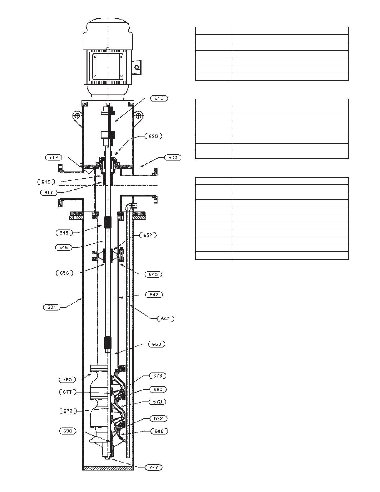
DISCHARGE HEAD ASSEMBLY
ITEM DESCRIPTION
600 DISCHARGE HEAD
610 COUPLING ASSEMBLY
617 SEAL HOUSING BEARING
616 SEAL HOUSING
779 SEAL HOUSING GASKET
620 MECHANICAL SEAL
COLUMN ASSEMBLY
642 COLUMN PIPE
645 COLUMN BOLTING
646 LINESHAFT
649 LINESHAFT COUPLING
652 BEARING RETAINER
656 LINESHAFT BEARING
643 CLEAN-OUT PIPE (OPTIONAL)
601 BARREL
BOWL ASSEMBLY
660 PUMP SHAFT
670 INTERMEDIATE BOWL
672 INTER. BOWL BEARING
673 IMPELLER
677 TAPERLOCK
680 WEAR RING (OPTIONAL)
760 HEX BOLT
692 SAND COLLAR
688 SUCTION BOWL/BELL
690 SUCTION BEARING
747 PLUG
Figure 1 VIC Pump with Solid Shaft Motor, Fabricated
T-Head, Mechanical Seal and Flanged Column
7
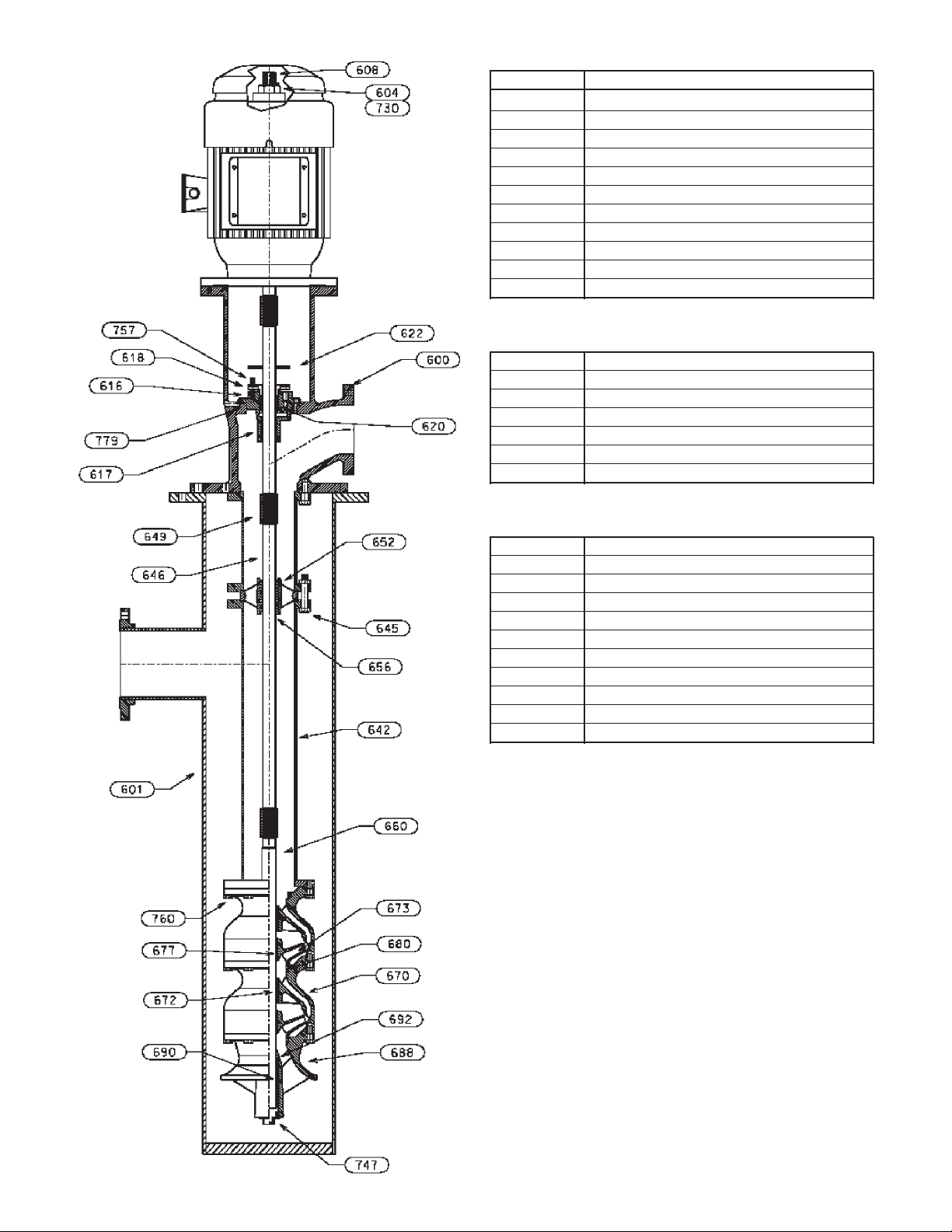
DISCHARGE HEAD ASSEMBLY
ITEM DESCRIPTION
600 DISCHARGE HEAD
604 ADJUSTING NUT
730 GIB KEY
608 HEAD SHAFT
616 STUFFING BOX
617 STUFFING BOX BEARING
618 SPLIT GLAND
620 PACKING
622 SLINGER
757 GLAND ADJUSTING SCREW
779 STUFFING BOX GASKET
COLUMN ASSEMBLY
642 COLUMN PIPE (FLG)
645 COLUMN BOLTING
646 LINESHAFT
652 BEARING RETAINER
656 LINESHAFT BEARING
649 LINESHAFT COUPLING
601 BARREL
BOWL ASSEMBLY
660 BOWL SHAFT
670 INTERMEDIATE BOWL
672 INTER. BOWL BEARING
673 IMPELLER
677 TAPERLOCK
680 WEAR RING (OPTIONAL)
760 HEX BOLT
692 SAND COLLAR
688 SUCTION BOWL/BELL
690 SUCTION BEARING
747 PLUG
Figure 2 VIC Pump with Cast L-Head, VHS Motor,
8
Packed stuffing Box and flanged column
Installation – SECTION 3
When pumping unit is installed in a potentially
explosive environment, the instruction after
the symbol must be followed. Personal
injury and/or equipment damage may occur if these
instructions are not followed. If there is any question
regarding these requirements or equipment is to be
modified, please contact a Goulds Water Technology
representative before proceeding.
FOUNDATION AND PIPING
SUB BASE (SOLE PLATE) OR BARREL FLANGE
INSPECTION
Sub base and sole plate are terms in common use to
describe a general class of solid steel plates mounted
in grout (or bolted to steel structures) at the pumpfoundation interface.
1. Remove the sub base from the pump discharge head
or barrel flange, when shipped assembled.
2. Completely clean the underside of the sub base. It is
sometimes necessary to coat the underside of the sub
base with an epoxy primer. (This is available as an
option.)
3. Remove the rust preventative solution from the
machined topside with an appropriate solution.
SITE WITH CONCRETE FOUNDATION
1. A pump should have adequate space for operation,
maintenance, and inspection.
2. Sub base mounted pumps are normally grouted
on a concrete foundation, which has been poured
on a solid footing. The foundation must be able to
absorb any vibration and to form a permanent, rigid
support for the pumping unit.
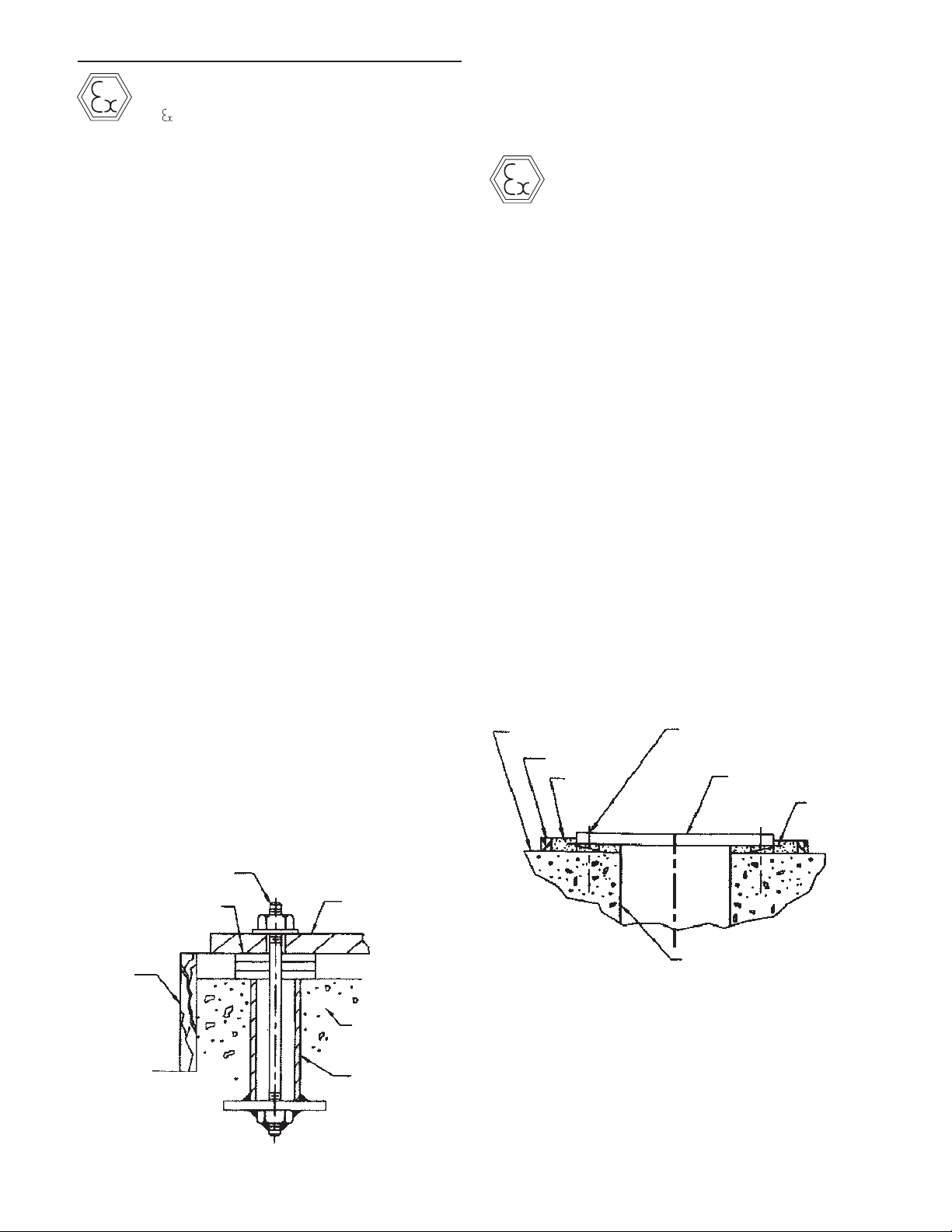
3. The foundation must be of adequate strength to
support the complete weight of the pump, plus the
weight of the liquid passing through it. A typical
installation will have bolts with a pipe sleeve 2 ½
times the bolt diameter embedded in the concrete.
Bolts should be sized and located in accordance
with the dimensions given on the Certified Pump
Outline Drawing, if provided. The pipe sleeve
allows movement for the final positioning of the
foundation bolts to conform to the holes in the sub
base flange. See Figure 3.
All equipment being installed must be properly
grounded to prevent unexpected static electrical
discharge. If not, a static electric discharge may
occur when the pump is drained and disassembled for
maintenance purpose.
4. Remove water and/or debris from anchor bolt holes/
sleeves prior to grouting. If the sleeve type bolts are
being used, fill the sleeves with packing or rags to
prevent grout from entering.
5. Carefully lower the sub base onto the foundation
bolts. Hand tighten the nuts.
6. Leveling the sub base may be done by several
methods. Two common methods are:
A. Using leveling wedges. This is shown in Figure 4.
B. Leveling nuts on the anchor bolts.
Regardless of the method, a machinist level must be
used for leveling.
NOTE: When using a machinist level, it is important
that the surface being leveled is free of all
contaminants, such as dust, to ensure an
accurate reading.
7. Level the sub base in two directions at 90º on the
machined surface. The levelness tolerance is 0.005
inches per foot for commercial, and 0.001 inches
per foot for API.
FOUNDATION
DAM
GROUT
CENTERLINE
ANCHOR BOLT
SUB BASE
LEVELING
WEDGES
DAM
BOLT
SHIMS
Figure 3
SUB BASE
FOUNDATION
SLEEVE
FLOOR SLEEVE
(OPTIONAL)
Figure 4
SUB BASE OR BARREL FLANGE GROUTING
1. Inspect foundation for dust, dirt, oil, chips, water,
etc. and remove any contaminants. Do not use oilbased cleaners as grout will not bond to it. Refer to
grout manufacturer’s instructions.
2. Build dam around foundation (See Figure 4).
Thoroughly wet foundation.
9
3. Pour grout between sub base or barrel flange and
WARNING
WARNING
CAUTION
concrete foundation, up to level of dam. Remove
air bubbles from grout as it is poured by puddling,
using a vibrator, or pumping the grout into place.
Non-shrink grout is recommended.
4. Allow grout to set at least 48 hours.
5. Tighten foundation bolts.
SITE WITH STRUCTURAL STEEL FOUNDATION
When the pump is mounted directly on a structural steel
frame, pumps shall be located directly over, or as near as
possible to, the main building members, beams or walls.
The barrel, discharge head mounting flange or sub base,
shall be bolted to the support to avoid distortion, prevent
vibration and retain proper alignment.
PUMP INSTALLATION
When pumping unit is installed in a potentially
explosive environment, the instruction after the
symbol must be followed. Personal injury and/
or equipment damage may occur if these instructions
are not followed. If there is any question regarding these
requirements or equipment is to be modified, please
contact a Goulds Water Technology representative before
proceeding.
Pumps of 20 feet (6 m) or less in length are usually
shipped assembled, with the exception of the driver,
mechanical seal with tubing and coupling assembly,
spacer or non spacer type. When provided, refer to the
Certified Pump Outline for the applicable base plate plan
for the location of anchor bolt holes.
INSTALLING A PARTIALLY ASSEMBLED PUMP
PIPING
Guidelines for piping are given in the “Hydraulic
Institute Standards”, available from: Hydraulic Institute,
9 Sylvan Way, Parsippany, NJ 07054-3802 and must be
reviewed prior to pump installation.
Never draw piping into place by forcing
the flange connections of the pump. Pipe
strain will adversely effect the operation of the pump
resulting in damage to the equipment and possible
physical injury.
1. All piping must be supported independently, and
line up naturally with the pump flange so that undue
pipe strain is not imposed on the pump.
2. DO NOT connect piping to pump until grout has
hardened and pump hold-down bolts have been
tightened.
3. It is suggested that expansion loops or joints, if used,
be properly installed in the discharge line. When
handling liquids at elevated temperatures expansion
joints are used, so linear expansion of piping will
not draw pumps out of alignment.
4. Carefully clean all pipe parts, valves and fittings,
and piping branches prior to assembly.
5. Isolation and check valves should be installed in
discharge line. Locate the check valve between
isolation valve and pump, this will permit inspection
of the check valve. The isolation valve is required
for regulation of flow, and for inspection and
maintenance of pump. The check valve prevents
pump or seal damage due to reverse flow through
the pump when the driver is turned off.
6. Increasers, if used, should be placed between pump
and check valves.
1. If a base plate was supplied, install as described in
Foundation/Piping Section (page 9).
2. Clean the mounting surface of the plate and clean
bottom surface of discharge head mounting flange.
3. Check that all fasteners on the pump are tight, as it
is recognized that transportation and handling may
result in bolt relaxation.
4. Install the barrel (can) to discharge head O-ring
(743).
5. Sling through discharge head holes or thread two
eyebolts through bolt holes in mounting flange and
hoist unit into position over foundation.
NOTE: Eyebolts or sling should be rated to handle
in excess of the pump weight (see Outline
Drawing).
6. Lower the unit and carefully guide it so that unit
does not strike the side of the base plate. Continue
to lower unit until the discharge head flange engages
and rests firmly on the plate, then secure with
capscrews provided.
7. When a lineshaft is shipped separately check shaft
for straightness; average total run out should not
exceed 0.005” T.I.R. (0.127mm) for 10 feet (3 m).
Shaft must be within tolerance prior to installation.
8. Refer to remainder of this manual for complete
assembly, startup, maintenance, disassembly and
recommended lubricants for the pump.
INSTALLING THE BOWL ASSEMBLY
Do not work under a heavy suspended
object unless there is positive support and
safe guards, which will protect personnel, should a hoist
or sling fail.
7. Cushioning devices should be used to protect the
pump from surges and water hammer if quickclosing valves are installed in the system.
10
Do not attempt to lift bowl assembly
by the pump shaft. This can result in
damaging the pump shaft.
1. Prior to installing the bowl assembly, check that
CAUTION
CAUTION
CAUTION
all capscrews are tight. Turn the pump shaft by
hand and make sure it turns freely. Remove all
accumulated dust, oil, or other foreign material
from the external surfaces.
2. If a suction strainer is provided, assemble it to the
suction bell (or suction bowl).
1. Coat a thin film of oil to the threads on the lineshaft
(646) and the coupling (649) (for non-galling
material, or Molykote if galling material).
2. Install threaded coupling onto pumpshaft by
threading it on for one-half its length. A fine
wire inserted in the drill hole at the center of the
coupling can be used as a gauge to determine
when the coupling is correctly positioned on the
pumpshaft. Remove the wire after installed the
coupling.
Use “MOLYKOTE” Dow Corning or
equal for all galling material such as 316
stainless steel.
INSTALLING THE COLUMN
OPEN LINESHAFT
Pump lineshafts are coupled with either threaded
or keyed couplings. Follow only those procedures
appropriate for the type of lineshaft coupling supplied.
When provided, see the Certified Pump Outline Drawing
for the number of column and shaft sections required.
Figure 5
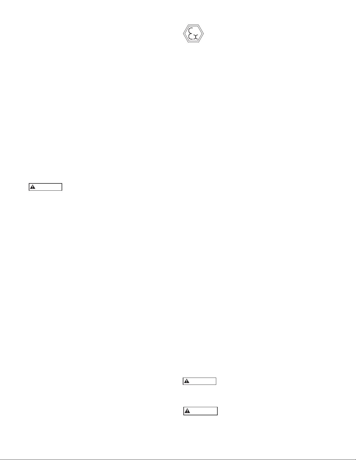
3. Place two I-beam supports across the base plate
opening, strong enough to safely support the weight
of the entire pump assembly. These I-beams should
be connected by threaded rods and nuts so as to
clamp them firmly together for the portion to be
supported. (See Figure 5).
4. Place a suitable hoist or derrick over base plate
opening with the hook in the center. Place the
elevator clamps just below the discharge bowl. Place
the elevator clamps just below the discharge bowl.
For flanged column install two threaded eyebolts
through the discharge bowl bolt holes 180º apart
for flanged column. For threaded discharge utilize
a lifting bail sized to handle the weight of the bowl
assembly and suction apparatus. Attach a sling to the
elevator clamps, eyebolts, or lifting bail and hoist it
into position.
5. Carefully lower bowl assembly, guiding the unit so it
does not strike the sides of the opening. Continue
to lower bowl assembly until the elevator clamps
or discharge bowl flange rests firmly on the I-beam
supports.
6. Place a cover over the discharge bowl opening to
prevent entrance of dirt or other foreign matter
until ready for installation of the column assembly.
Do not drop any foreign object into the
bowl assembly. Such an object can cause
serious damage to the pump and any downstream
components. Any foreign object dropped into the bowl
assembly must be retrieved prior to continuing assembly.
THREADED COUPLING INSTALLATION
NOTE: Shaft threads are left-handed.
When the threaded coupling is not installed on the
pumpshaft, install as follows:
1. Check the headshaft (608) and lineshaft (646) for
straightness. Average total runout should be less
than 0.0005” T.I.R. per foot, not to exceed 0.005”
T.I.R. for every 10 feet of shafting.
2. Hoist the first piece of lineshaft over the bowl
assembly. Lower the lineshaft until the bottom end
is properly aligned with the coupling of the pump
shaft. Apply a thin film of oil to the threads on the
lineshaft (646) and the coupling (649) (for nongalling material, or Molykote if galling material).
Use “MOLYKOTE” Dow Corning or
equal for all galling material such as
316 stainless steel.
3a. With lineshaft in the proper position on the
coupling, screw lineshaft into the coupling manually
until resistance is felt. A fine wire inserted in the
hole at the center of the coupling can be used as a
gage to determine when the coupling is correctly
positioned on the shaft. Remove the wire after
installing the shaft. Completely tighten the joint
by using a pair of pipe wrenches. Use care not to
damage any bearing journal areas on the shaft.
NOTE: Shaft threads are left-handed.
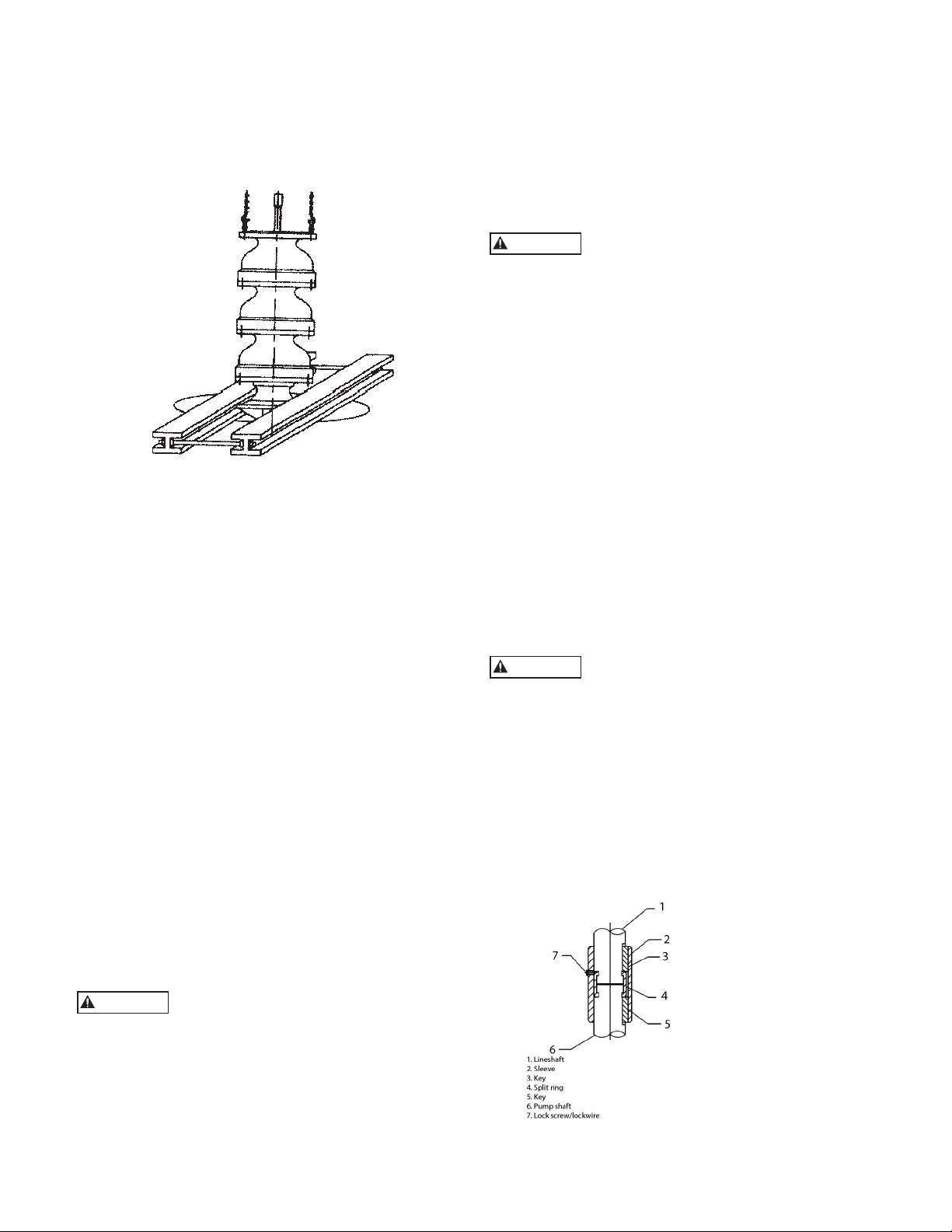
3b. With a keyed coupling
insert the key into the
pump shaft. Lower the
sleeve over the pump shaft,
to approximately 1.0 in
(25.4 mm) below the top
of the shaft. Then lower
the lineshaft until it touches
the pump shaft. Insert the
split ring into the grooves
of the pump shaft and
lineshaft. Raise the sleeve
until it covers the split ring,
then insert the key into the
lineshaft. Raise the sleeve to the top of the key and
secure the sleeve to the split ring with a lock screw
and lock wire.
11

CAUTION
WARNING
CAUTION
4. Install two eyebolts diametrically opposite the upper
flange of the bottom column (644). Attach a sling to
the eyebolts and to the hoist hook. Lower column
section until the flange engages the flanged top bowl
register. Insert as many bolts through both flanges
as possible. Lift column assembly high enough to
allow rotation of the supports. Install and tighten
remaining capscrews gradually in diametrically
opposite pairs until all are uniformly tightened.
5. Lift the assembly and remove the elevator clamp or
supports and slowly lower the bowl and the column
assembly. Place supports on the base plate and
continue to lower the assembly until the column
elevator clamps or column flange comes to rest on
the supports.
NOTE: Normally, the bearing retainer will be integral
with column. The top flange of the column will
have male register and the bottom flange of the
column will have a female register. If you have
separate bearing retainers, there will be a female
register in the flange at both ends of the column.
Follow step 6 below.
6. Place the bearing retainer (652) with bearing (656)
over the shaft and fit the retainer in the female
register of the flange. Make sure the contact faces in
the flanges are clean. Use a file to remove nicks or
dings.
7. Install threaded coupling (649) on the protruding
end of the lineshaft (646), if required.
8. Assemble next column (642) section, or top column
(641) as required, and make sure bottom column
register (or bearing retainer (652)) engages the top
column register, and secure with capscrews (760B)
and hex nuts (735A) provided. Tighten capscrews
into hex nuts gradually and uniformly.
9. Repeat the preceding procedures until all column
sections required have been installed.
Do not drop any foreign object into the
column assembly. Such an object can
cause serious damage to the pump and any downstream
components. Any foreign object dropped into the column
assembly must be retrieved prior to continuing assembly.
INSTALLING THE DISCHARGE HEAD
VIC Pumps are provided with either “T” type or “L” type
head. Install the discharge head as follows:
1. If the stuffing box (See Fig. 6) is assembled to the
head, remove it and all the attached piping.
2. When a mechanical seal is provided it is shipped
separately.
3. Remove coupling guard if provided. Attach a sling
to the lifting lugs on the side of the discharge head
or through windows and hoist discharge head over
the protruding top shaft.
Eyebolts or sling should be rated to handle
in excess of the pump weight (see Outline
Drawing).
Do not bump or scrape the shaft protruding above the column. This could result in
bending or damaging the shaft.
12
4. Orient the discharge head in the required position
and lower the head. Centering the vertical hole with
the top shaft protruding above the column until the
discharge head engages the column flange. Install
capscrews and secure discharge head to the column
flange. Tighten capscrews gradually in diametrically
opposite pairs.
5. Lift the pump assembly high enough to allow rotation of the supports. Realign and lower assembly.
Install and tighten remaining capscrews. Repeat
the rotating and the tightening procedure until all
capscrews are uniformly tight.
6. Hoist the discharge head by lifting lug and remove
the elevator clamp attached to column.
7. Remove the support timbers or I-beams and clean
the top of barrel flange. Orient the discharge head
in the required position.
NOTE: Sling should be rated to handle in excess of the
pump weight.
8. Lower bowl, column and head assembly, until
discharge head mounting flange engages with the
barrel flange. Secure discharge head to barrel.
Check the levelness of the discharge head in all
directions, utilizing a machinist level across the
driver’s mounting surface of the discharge head.
9. Check whether the top shaft (or stub shaft) is in
the center of the stuffing box bore. If not, the shaft
must be centered by shimming the head base and the
sub base (or the foundation).
10. Rotate the shaft approximately 90º. Check again
whether the shaft is at the center of the stuffing box
bore or not. If not, either the top shaft is bent or the
first shaft below it did not butt properly. Correction
must be made before the installation procedures can
proceed.
INSTALLING THE STUFFING BOX
Assemble stuffing box as shown in Figure 6.
1. Clean the surface of the discharge head where
the stuffing box will be mounted and remove any
nicks or burrs with a fine flat file. Position gasket
on surface. Slide stuffing box (616) down over
headshaft and into position on the gasket. Secure
stuffing box with capscrews.
2. Grease the packing ring (620) for easier installation.
3. Twist the packing ring sideways to get it around the
shaft easily. Start the first ring into the stuffing box.
When the entire ring is worked in using the fingers,
tamp it down using a split wood bushing (or equal)
and push the packing ring down firmly. It must seal
on the shaft and bore of the stuffing box. Install
three (3) rings in this manner. Stagger ring joints
90 degrees apart. The split gland may be used as a
tamper for the top ring.
4. Insert lantern ring (622) into stuffing box. Be sure
it is properly positioned so that it aligns with the
lubrication passage in the stuffing box.
5. Insert three (3) additional rings of packing. Stagger
ring joints 90º apart.
6. Install the split gland and screw nuts on the split
gland studs. Tighten nuts then relieve the nuts and
tighten finger tight.

Check that the split gland is square in the
CAUTION
CAUTION
CAUTION
CAUTION
stuffing box. Cocking can cause uneven
compression of packing and damage to the shaft or sleeve
and heat up the shaft and stuffing box.
7. The stuffing box is shipped with both ports plugged.
If the discharge pressure is over 100 psi, remove the
plug on Port “A” and attach a bypass (relief) line. If
the discharge pressure is over 200 psi, remove the
plug on Port “B” and attach another bypass line.
8. Final adjustment of the stuffing box must be made at
pump start up.
9. A properly packed stuffing box should be loose
enough to allow the shaft to be turned manually
and must have leakage (see page 22 – Packing
Adjustment).
Do not over tighten packing or excessive
wear can occur on the shaft or sleeve.
(619) STUD (2)
(735) HEX NUT
(2)
PORT "A"
(624) BYPASS LINE
(618) GLAND
PORT "B"
shaft packing. When further clean up is required,
protect by covering the inside of the pump seal
housing. Remove burrs, nicks and sharp corners by
using a strip of emery cloth over the shaft threads.
File threads around the keyway with a smooth mill
file or emery cloth. Sharp edges must be rounded.
3. Remove all chips and dust from the shaft area.
4. Check that all rotary unit parts of the seal fit over
the shaft. A pre-check may be made by removing the
O-ring(s) from the cartridge sleeve Inside Diameter
(ID) and then installing the seal on the shaft. Further
shaft clean up will be necessary when the seal will
not pass all the way into the seal housing.
5. Remove the seal after the pre-check, and re-install
the sleeve O-ring(s).
6. Sparingly lubricate the shaft and sleeve ID with
the lubricant included with the mechanical seal or
recommended by the mechanical seal manufacturer.
The following lubricants may be used, for water service, when no lubricant is supplied or recommended
by the mechanical seal manufacturer.
• Light oil (SAE #10 or 20)
• Dow Corning #4 Grease
• Silicone lubricant
• Wax or clay
• Soapy water
(621) O-RING
(622) LANTERN
RING
(620) PACKING
(6 RING)
(616)
STUFFING BOX
(617) BEARING
Figure 6
INSTALLING THE MECHANICAL SEAL
The vertical turbine pumps are usually supplied with
cartridge type mechanical seals, shipped assembled
- ready for installation, when mechanical seals are
supplied. Instructions for installing mechanical seals
are provided by the seal manufacturer. Consult the seal
manufacturer’s instructions (furnished with the seal) for
information on the type of seal used. Additionally, refer
to factory furnished outline drawing and seal piping
schematic on complex seal piping arrangements.
GENERAL REQUIREMENTS FOR ALL SEALS
1. Check surfaces at the face of the seal housing and
at the bottom of the seal housing to insure that they
are clean, flat and free of burrs. The face surface
must be smooth to form a good sealing surface for a
gasket or O-ring.
2. Check that shaft is smooth, and free of burrs, nicks
and sharp corners that could ruin the O-ring or
Oil based lubricants will damage EPR / EPDM
elastomer O-rings. Silicone lube and soapy water are
safe for EPR / EPDM elastomer O-rings.
7. Install the O-ring or gasket, between the seal
housing and seal. Install the seal over the shaft and
ease it into position against the face of the seal box.
Take care when passing the sleeve and O-ring over
keyways or threads to avoid damaging the O-ring.
Do not bump carbon members against the
shaft as they may chip, crack or break.
8. Position seal gland on discharge head seal housing
and secure with capscrews (or nuts for studs)
provided. Tighten capscrews gradually and
uniformly in a criss-cross pattern, taking 2 or 3
passes.
Do not over tighten capscrews on gland.
This can distort seal seat and cause seal
failure.
9. Install all seal piping as required. Prior to making
final connections of sealing liquid pressurizing
lines, make sure the seal housing and all sealing
liquid lines are flushed free of dirt, scale and other
particles that would be abrasive to the sealing faces.
10. The Driver and Coupling must now be installed
before the driver installation can proceed. See page
14 - INSTALLATION OF A HOLLOW SHAFT
DRIVER or page 16 - INSTALLATION OF A
SOLID SHAFT DRIVER as appropriate.
13
WARNING
MECHANICAL SEAL ALIGNMENT
CONCENTRICITY OF MOTOR SHAFT
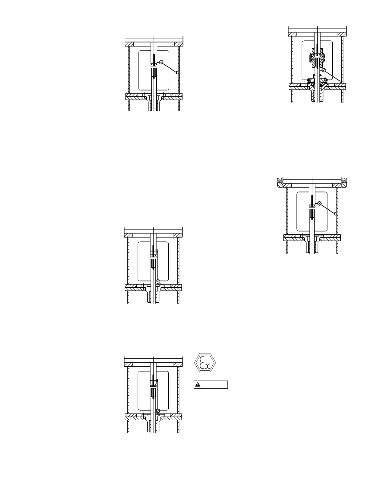
1. Install the dial indicator as
shown, with the base attached
to the motor support.
2. Rotate the motor shaft by
hand while you read the dial.
3. Make sure that the runout
does not exceed NEMA
standards, 0.002 in (0.05
mm) maximum TIR.
4. If the indicator reads higher
than 0.002 in
(0.05 mm)TIR, loosen the four motor hold-down
bolts and relocate the motor on the motor base
register.
5. Obtain the desired position.
6. Tighten the hold-down bolts and repeat the
indicator reading.
Note: Adding or removing shims between the motor
and the discharge head helps alignment in the
vertical direction. The motor may also have to be
adjusted in the horizontal direction for alignment.
FLATNESS OF THE SEAL HOUSING
For this measurement, remove the mechanical seal if the
dial indicator stylus cannot rotate 360° on the top surface
of the seal gland.
1. Install the dial indicator as
shown, with the base 1)
Remove the lower coupling
components and attach the
base of the dial indicator to
the motor shaft.
2. Place the stylus at the top
surface of the seal gland, or
at the top surface of the seal
housing.
3. Slowly rotate the motor
shaft 360°.
4. Check that the face of the seal housing is square with
the shaft to within 0.002 in (0.05 mm) TIR.
CONCENTRICITY OF THE SEAL HOUSING
This measurement requires that you remove the
mechanical seal.
1. Install the dial indicator as
shown.
2. Rotate the motor shaft
by hand and run the
indicator in the insidemachined surface of the
seal housing in order to
determine the concentricity.
3. If the indicator reads
higher than 0.004 in (0.10
mm) TIR, loosen the four
motor hold-down bolts and
relocate the motor on the motor base register.
4. Obtain the desired position.
5. Tighten the hold-down bolts and repeat the
indicator reading.
14
CONCENTRICITY OF THE HEADSHAFT
1. Reinstall the mechanical
seal if it was removed for
the flatness or concentricity
measurement.
2. Install the coupling assembly
and adjust the impeller.
3. Attach the base of the dial
indicator on the discharge
head or motor support.
4. Place the stylus on the shaft
between the top of the seal
and the bottom of the pump coupling.
5. Slowly rotate the motor shaft 360°.
6. Check that the shaft runout is within 0.004 in
(0.10 mm) TIR, or as required by specification.
7. Drill and dowel the pin in three places in order to
secure the motor to the motor base after you obtain
the required runouts.
CONCENTRICITY OF MOTOR SHAFT USING
JACKSCREWS
1. Install the dial indicator
as shown, with the base
attached to the motor
support.
2. Rotate the motor shaft by
hand while you read the
dial.
3. Make sure that the runout
does not exceed NEMA
standards, 0.002 in (0.05
mm) maximum TIR.
4. If the indicator reads higher than 0.002 in
(0.05 mm) TIR, using the jackscrews relocate the
motor on the motor base (sometimes no register).
5. Obtain the desired position.
6. Tighten the hold-down bolts (not the jackscrews)
and repeat the indicator reading.
Note: Adding or removing shims between the
motor and the discharge head helps alignment in
the vertical direction. The jackscrews are provided
to adjust the motor in the horizontal direction for
alignment.
INSTALLING THE DRIVER
When installed in a potentially explosive
environment, please ensure the motor is
properly certified.
Serious damage may result if pump is run
in the wrong direction.
NOTE: When pump is supplied with a thrust pot, do not
secure the driver to discharge head until after the
thrust pot and flexible coupling are installed.
INSTALLATION OF A HOLLOW SHAFT DRIVER
This refers to either VHS type electric motors or hollow
shaft type gear drives. A small paragraph will be devoted
to combination electric motor and right angle gear
drives.
Do not work under a heavy suspended
CAUTION
WARNING
object unless there is a positive support
and safe guards which will protect personnel should a
hoist or sling fail.
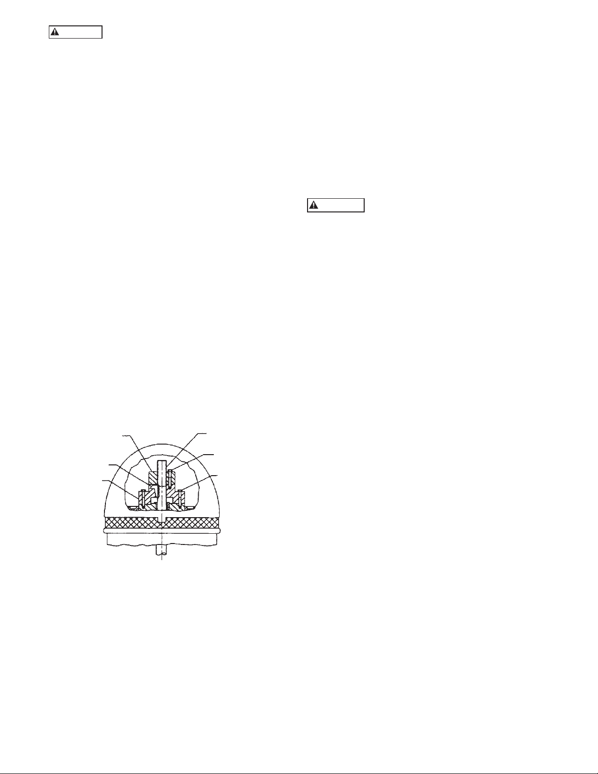
1. The driving mechanism of all hollow shaft driver is
shown on Figure 7. The head shaft (608) extends up
through the quill or hollow shaft of the driver and
is held in place by an adjusting nut (604), which not
only carries all the static and hydraulic thrust of the
impellers and shaft, but also provides the adjustment
for the impeller clearances. The head shaft is
connected to top shaft (or stub shaft) by a threaded
coupling or a rigid flange coupling.
2. Attach a sling to the lifting lugs of driver and hoist
the driver up. Inspect the mounting surface, register
and clean these surfaces thoroughly. If any burrs
are found, remove burrs with a smooth mill file,
cleaning thoroughly afterward.
3. For motor, orient the motor conduit box in the
required position. For the right angle gear, orient
the input shaft to the desired position. Align the
driver mounting holes with the mating tapped holes
on the discharge head. Lower the driver until the
registers engage and the driver rests on the discharge
head. Secure driver with capscrews provided.
4. Lubricate the driver bearings in accordance with
instructions given on lubrication plate attached to
the driver case. (Or refer to IOM of the driver)
5. After lowering and orienting the driver as explained
above, remove the drive coupling and the hold
down bolts (See Figure 16). Be sure to mark the
location of the coupling before removing it.
(604) ADJUSTING
NUT
(730) GIB KEY
DRIVE
COUPLING
HEAD SHAFT (608)
CAPSCREW (760)
ADJUSTING NUT
HOLD
DOWN BOLT
top flange, discharge head base flange to base plate
or the base plate itself could be out of level. If the
latter, shimming between it and discharge head base,
will correct it. Also, check concentricity of motor to
motor-stand (if provided) to discharge head.
9. With the motor in place and the head shaft
projecting through the motor quill shaft, make
temporary electrical connection to check the motor
rotation. (Be sure to remove the ratchet pins or balls
before checking motor rotation.) Motor must rotate
counter-clockwise when viewed from the top. See
arrow on pump name plate. If motor does not rotate
counter-clockwise, you can change the rotation by
interchanging any two leads.
Never check motor rotation with the drive
coupling in place. The bore clearance
between the drive coupling and the pump shaft O. D.
is so close that should the motor spin with this shaft
stationary, galling and locking together is very likely to
take place.
10. Install motor drive coupling. (Be sure to line up the
match mark made at step 5.) Insert the ratchet pins
if a non-reverse ratchet is used. Match the coupling
lugs with corresponding holes in motor. Tighten
hold down bolts evenly, making sure driver coupling
is properly seated in the register fit.
11. Fit gib key (730) into keyway, by filing if necessary,
to where there is a snug but sliding fit. This key
must be able to be removed by gentle leverage with
a screwdriver under it.
12. Be careful that the gib key (730) is not too high so
as to hold up the adjusting nut (604) from seating
on the drive coupling. If it is, cut off some length of
the key.
13. Install adjusting nut (604) to hand tight.
COMBINATION ENGINE AND MOTOR DRIVES
1. On combination drivers, the motor is invariably on
top with a projecting head shaft extension.
Figure 7
6. Lower the head shaft through the motor quill shaft
to meet the shaft coupling. Apply a thin film of oil
to head shaft threads (if non-galling material) and
screw into the shaft coupling (located above the
stuffing box). Make sure the shaft is not damaged in
any way. Tighten the joint.
7. Check that the head shaft centers inside the driver
quill shaft within 0.06” (1.5mm). If it does not,
misalignment is indicated.
8. Any head shaft misalignment with driver quill
shaft could be caused by a bent head shaft, burrs,
or foreign matter between shaft ends or any of the
mounting flanges: motor flange to discharge head
2. Follow all procedures outlined in the previous
paragraph, except that the motor must be lowered
over this extended head shaft and great care must be
taken to center it exactly so as not to bump or misalign the shaft while the motor is being lowered into
place.
3. There are several methods of running engines
without electric motors and vice versa, requiring
simple adjustment to the combination drive, but
they are too numerous to mention here and can be
obtained from the gear manufacturers instructions
included with the shipment.
15

IMPELLER ADJUSTMENT FOR ALL HOLLOW
WARNING
WARNING
SHAFT DRIVES
NOTE: Shaft adjustment up or down is accomplished by
turning the adjusting nut (604) Figure 8.
INSTALLATION OF A SOLID SHAFT DRIVER
NOTE: When pump is supplied with a thrust pot, do
not secure driver to discharge head until after
the thrust pot and flexible coupling are installed.
NOTE: There are five holes in the adjusting nut and
only four in the motor coupling. See Figure 8.
1. With shafting all the
way down and the
impellers resting on
their seats, turn the
(604) ADJUSTING NUT
LOWER IMPELLER
adjusting nut (604)
in counter-clockwise
RAISE IMPELLER
direction, thus lifting
the shaft, until the
impellers just clear their
A
seats and the shaft/
motor turns free by
hand. This removes
all deflection from the
B
E
shaft.
2. For enclosed impellers,
make another two turns
MOTOR COUPLING
ROTATION
on the adjusting nut.
(3 turns for 12 thread/
inch shaft) Line-up
one of the holes in
C
the adjusting nut
with the nearest
hole in the driver
coupling. Insert
the capscrew
in the hole and
tighten it.
D
Do not work under a heavy suspended
object unless there is a positive support
and safe guard which will protect personnel should a
hoist or sling fail.
The coupling between the driveshaft and the head shaft
may be a non-spacer type (see Figure 9), or a spacer type
(see Figure 10). The latter is used on pumps furnished
with a mechanical seal to permit servicing of the seal
without removal of the driver.
F
1. Attach a sling to the lifting lugs of driver, hoist
motor, inspect the mounting surface, register, and
shaft extension, and clean these surfaces thoroughly.
If any burrs are found, remove burrs with a smooth
mill file, cleaning thoroughly afterward.
2. Orient the motor conduit box in the required
position. Align the motor mounting holes with the
mating tapped holes on the discharge head. Lower
the motor until the registers engage and the motor
rests on the discharge head. Secure motor with
capscrews provided.
H
3. On drivers having a nonreverse ratchet or pins,
manually turn the driver shaft clockwise viewed
from the top until the nonreverse ratchet or pins
fully engage.
G
4. Lubricate motor bearings in accordance with
instructions given on lubrication plate attached to
the motor case.
Figure 8
NOTE: 1.00” and 1.18” diameter shafts are 12 thread
per inch (tpi), 1.50" through 2.44" are 10 tpi, all
larger sizes are 8 tpi.
3. For Open Impellers, Align hole “A” in the adjusting
nut (604) and hole “C” in the driver coupling
(See Figure 8) or whatever similar holes are in like
position. If care is exercised, this will give an initial
impeller clearance of 0.001” to 0.003” depending
on shaft size or the pitch of the thread.
4. Insert capscrew into hole “B” provided these are
the nearest matching holes for counter-clockwise
rotation of adjusting nut, turn adjusting nut counterclockwise until holes “B” and “D” line up. This
gives 1/20 of a turn which is 0.004” on 12 tpi shaft
or 0.005” on 10 tpi shaft.
5. Normal impeller clearance for the open impeller is
considered to be 0.015” for the first 10 feet of the
column length and 0.010” additional clearance for
each 10 ft of length thereafter. This can be reduced
in some instances where is necessary, but should
not be attempted without consulting the factory or
factory serviceman is present.
NOTE: Please read and follow the motor manufacturer’s
instructions before lubricating the motor
bearings. Too much lubricant can cause the
bearings to overheat prematurely.
The motor must not be tested for direction
of rotation when coupled to the pump.
If pump should rotate in the wrong direction, serious
damage to the pump and motor would result. Also
serious injury to personnel could result.
5. Make temporary electrical connections according
to tagged leads or diagram attached to the motor.
Motor must rotate counterclockwise when viewed
from the top. See arrow on pump name plate. If
motor does not rotate counterclockwise, you can
change the rotation by interchanging any two leads.
6. Motor shaft end play adjustment: if required,
motor shaft end play shall be checked with a dial
indicator prior to connecting the pump coupling to
the solid shaft motor. Consult the applicable motor
manufacturers instruction manual for detailed
information on motor shaft end play.
16
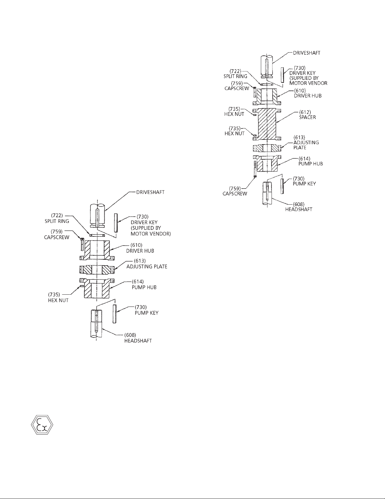
COUPLING INSTALLATION: (SEE FIGURES 9 and 10)
1. Check all mating faces with a fine flat file before
installation. Remove all burrs from face.
2. Apply a thin film of oil on the pump key (730) and
insert key into headshaft keyway seat.
3. Gently lower pump hub of coupling (614) onto
headshaft.
4. Thread on the adjusting plate (613) onto the
headshaft until flush with top of the headshaft.
5. Clean driver shaft by removing all grease and burrs.
Try to fit the key on the driver hub (610) before
installing it to the driver shaft.
6. Apply a thin film of oil to the driver key (730) and
insert key into drive shaft keyway seat. Place the
driver hub (610) onto the drive shaft and with key
slide it up the drive shaft until the annular groove
is exposed. Install split ring (722) in the groove and
slide driver hub down over the split ring to capture
it.
for the specific unit. If the pump has thrust pot, do not
adjust the impeller position until the thrust has been
installed and adjust the impeller position by using the
adjust nut on the thrust pot.
Figure 9
7. If the pump is supplied with an adjustable spacer
coupling (see figure 10), install spacer (612) between head shaft and driveshaft hubs. Secure with
capscrews (759) and hex nuts (735).
IMPELLER ADJUSTMENT
Improper impeller adjustment could cause
contact between the rotating and stationary
parts, resulting in a spark and heat generation.
Figure 10
NOTE: Mechanical seal, when provided, must not be
secured to the shaft prior to impeller adjustment.
(open or enclosed type impellers). Shaft must
move up or down within the seal Assembly.
For pumps handling liquids between –50º to
200º F, impeller adjustment can be made under
ambient conditions. For liquids in excess of
this range, it is recommended that impeller
adjustment be made after the pump surface
temperature has reached an equilibrium when
charged with the pumpage. In those cases, where
this is not feasible due to safety consideration
or impossible due to external ice build up in
cryogenic applications, refer to factory for
specific instructions.
OPEN IMPELLERS
1. With the impellers touching the bottom of the
bowls, turn the adjusting plate (613) towards the
driver hub (610) or spacer (612) obtain 0.015 inch
clearance between the adjusting plate and driver
hub or spacer for the first 10 feet of column. Add
0.010” for each additional 10 feet of column. See
figure 10 or 11. Note: The determination of driver
shaft end play can be critical and should be added
to this setting. For larger pumps over 8”, this
amount may be too little; please refer to Outline
Drawing.
Impeller adjustment is identical for all motors and
right angle gear drives. Adjustment is accomplished by
turning the adjusting plate (613). (See figure 11 or 12).
The correct adjustment is listed on the Outline Drawing
17

2. After impeller adjustment, align adjusting plate (613)
WARNING
with the pump hub (614), and tightly draw coupling
flanges together with capscrews (759) and nuts
(735). (See figure 9 and 10).
3. Check shaft run out with dial indicator. For
mechanical seal installation, the run out should be
0.005 or less.
4. Set seal after impeller adjustment. Securely tighten
all set screws in the collar. Remove the spacer
between the gland plate and collar. Retain spacer for
future resetting of seal.
ENCLOSED IMPELLERS
For enclosed impellers obtain the clearance between the
adjusting plate and driver hub or spacer as specified on
the outline drawing. See Figure 11 or 12.
INSTALLING THE GREASE LUBRICATED THRUST POT
This type of thrust pot and the motor stand are
assembled on the discharge head by the factory. This
thrust pot is designed to be used with NEMA Vertical
C-face motors. The motor shaft and the pump shaft have
to be coupled with flexible coupling.
NOTE: When impellers are reset, the seal must also be
reset.
Figure 11
INSTALLATION:
1. Install both coupling halves prior to mounting
the motor. Refer to the coupling manufacturer’s
instructions.
2. Using the lifting lugs on the motor, carefully lower
the motor onto the motor stand of the thrust pot
(See Figure 13) and align the bolt holes.
3. Install the bolts finger tight.
4. Make temporary electrical connections according
to tagged leads or diagram attached to the motor.
Motor must rotate counterclockwise when viewed
from the top. See arrow on pump name plate. If
motor does not rotate counterclockwise, you can
change the rotation by interchanging any two leads.
Before beginning any alignment procedure,
make sure driver power is locked out.
Failure to lock out driver power will result in serious
physical injury.
ALIGNMENT OF FLEXIBLE COUPLING:
Alignment of the pump and motor is extreme importance
for trouble-free mechanical operation. Straight edge
alignment by an experienced installer proves adequate for
most installations.
1. Check for coupling alignment by laying a straight
edge across both coupling rims at four points 90º
apart.
2. Move motor until straight edge rests evenly at each
position. Repeat procedure until correct alignment is
achieved.
3. Install flexible sleeve between the hubs per the
manufacture’s instructions.
4. Tighten all motor bolts.
NOTE: Be sure the relief fitting (#11 in Figure 13) is
clear of paint or any other obstructive material.
Otherwise it will cause premature failure of the
thrust pot and is not covered under warranty.
Figure 12
18

ITEM DESCRIPTION
1 Motor stand
2 Headshaft
3 Bearing housing
4 Bearing
5 Top seal
6 Snap ring
7 Lock nut
8 Lock washer
9 Lower seal
10 Grease lube fitting
11 Grease relief fitting
12 Hex tap bolt
13 Hex nut
14 Hex capscrew
Figure 13 – Grease Lubricated Thrust Pot
3. Lower the drive shaft through the quill of the thrust
pot assembly to meet the shaft coupling. Apply a
thin film of oil to the head shaft thread and screw
into the shaft coupling.
4. For unit with mechanical seal and flanged coupling,
install the spacer flange coupling as instructed on
page 16.
5. Install the gib key (#16) into the drive shaft and the
hollow shaft clutch.
6. Install the adjusting nut (#17) to hand tight.
7. With shafting all the way down and the impellers
resting on their seats, turn the adjusting nut (#17)
in counter-clockwise direction, thus lifting the shaft,
until the impellers just clear their seats and the
shaft/motor turns free by hand. This removes all
deflection from the shaft.
8. Line-up one of the holes in the adjusting nut with
the nearest hole in the driver coupling. Insert the
capscrew in the hole and tighten it.
NOTE: 1.00” and 1.18” diameter shafts are 12 tpi, 1.50"
through 2.44" are 10 tpi, all larger sizes are 8 tpi.
9. Install the bottom of the flexible coupling to the top
of the drive shaft.
10. Attach a sling to the lifting lugs of driver and hoist
the driver up. Inspect the mounting surface, register
and clean these surfaces thoroughly. If any burrs
are found, remove burrs with a smooth mill file,
cleaning thoroughly afterward. Temporarily attach
the top half of the flexible coupling to the motor
shaft.
11. Orient the motor conduit box in the required
position. Align the driver mounting holes with the
mating tapped holes on the discharge head. Lower
the driver until the registers engage and the driver
rests on the thrust pot assembly. Secure driver with
capscrews provided.
12. Secure the flexible coupling assembly.
INSTALLING THE OIL LUBRICATED THRUST POT
If the unit is supplied with a thrust pot (see Figure 14),
the thrust pot should be installed on top of the discharge
head or motor stand before installing the driver. The
driving mechanism of the thrust pot assembly is similar to
the hollow shaft motor. (See Figure 7)
1. Attach a sling to the thrust pot assembly through
the windows on the motor adapter and hoist the
assembly over the top of the discharge head.
2. Clean the mounting face with a flat file to remove
any burr of the discharge head and the thrust pot.
Lower the thrust pot assembly and orient it so that
the bolt hole on the base of the thrust pot and the
top flange of the discharge head are lined up. Install
all the bolts to secure the assembly to the discharge
head.
13. Install the coupling guard.
14. Fill the oil reservoir with recommended oil.
19

ITEM DESCRIPTION
1 Thrust Pot Body
2 Tube - Oil Retaining
3 Thrust Bearing
4 Capscrew - Head to Thrust Pot
5 Washer - Head to Thrust Pot
6 Hex Nut - Head to Thrust Pot
7 Roller Bearing
8 Bearing Seat
9 Allen Head Screw
10 Capscrew - Motor Adapter to Motor or Thrust Pot
11 Washer - Motor Adapter to Motor or Thrust Pot
12 Gasket
13 Capscrew
14 Non-reverse Pin
15 Socket Head Screw
16 Gib Key
17 Adjusting Nut
18 Coupling Guard
19 Setscrew
ITEM DESCRIPTION
20 Flexible Shaft Coupling
21 Gib Key
22 Key (Motor Shaft)
23 Setscrew
24 Round Head Screw for Coupling Guard
25 Washer Coupling Guard
26 Motor Adapter
27 Capscrew - Adjusting Nut
28 Washer - Adjusting Nut
29 Retaining Ring
30 Hollow Shaft Clutch
31 Non-reverse Plate
32 Pipe Plug - Oil Filling
33 Retaining Ring
34 Hollow Shaft
35 Shaft Sleeve
36 Sight Gauge
37 Pipe Plug - Oil Drain
20
Figure 14 – Oil Lubricated Thrust Pot

Pump Startup And Operation – SECTION 4
WARNING
WARNING
WARNING
CAUTION
PRE-START PROCEDURE
Consult the applicable manufacturer’s instructions for
detailed information for the prime mover (electric motor,
engine or steam turbine), coupling, driveshaft, gear
driver. Prior to startup, check the following:
1. Confirm that the following procedures described
in the “Installing the Drivers” sections have been
performed:
STARTUP PRECAUTIONS
1. All equipment and personal safety related devices
and controls must be installed and operating
properly.
2. To prevent premature pump failure at initial start-up
due to debris in the pipe system, ensure the system
has been adequately cleaned and flushed.
3. Variable speed drivers should be brought to rated
speed as quickly as possible.
A. Wiring of Driver.
B. Driver must rotate counterclockwise (CCW)
when viewed from above.
Serious damage may result if pump is run
in the wrong direction.
Do not check motor rotation unless motor
is bolted to pump and drive coupling is
match marked and removed.
Be sure to install the coupling guards
around all exposed shafts and couplings
before start up of the pump. Failure to comply may result
in severe personnel injury or death.
C. Check alignment of pump and driver.
D. Impeller adjustment has been made.
E. Mechanical seal lock collar is attached to shaft.
2. For open lineshaft pump, make sure the stuffing box
relief (bleed) line is connected (if applicable).
3. For pump with mechanical seal, make sure mechani-
cal seal is properly lubricated and all piping to seal is
connected. Also, check that all cooling, heating and
flushing lines are operating and regulated.
4. Open the air release system isolation valve. Adjust
the air release system throttling device so that it is
partially open. It should not be closed or fully open.
NOTE: Not exhausting the air or exhausting it too fast
can damage the pump.
5. All connections to driver and starting device match
wiring diagram. Voltage, phase, and frequency on
motor nameplate agree with line current.
6. Rotate shaft manually to ensure impellers are not
binding.
4. Variable speed drivers should not be adjusted or
checked for speed governor or over-speed trip
settings while coupled to pump at initial startup. If
settings have not been verified, uncouple the unit
and refer to driver manufacturer’s instructions for
assistance.
5. Running a new or rebuilt pump at slow speeds
may not provide enough flow to adequately flush
and cool the stuffing box bushing’s close running
surfaces.
6. Pumpage temperatures in excess of 200º F (93º C)
will require warm-up of pump prior to operation.
Circulate a small amount of pumpage through the
pump until the casing temperature is within 100º
F (38º C) of the pumpage temperature and evenly
heated.
PRIMING
The pump must be properly vented
through the discharge head/barrel vent
connections. This is especially important for fluids with
suction pressure close to their vapor pressures. Vent
piping must be continuously rising back to source so that
fluid cannot collect in the vent line.
The first stage impeller must always be completely
submerged. Pump must not run dry as the rotating parts
within the pump may gall and seize to the stationary
parts. The parts must be lubricated by the liquid being
pumped.
NOTE: NPSHa must always exceed NPSHr as shown on
Goulds Water Technology performance curves.
NOTE: Pump must never be throttled on the suction
side by allowing suction strainer to become
clogged.
PUMP STARTUP
7. Verify that driver bearings are properly lubricated
and check oil level in housing.
8. Check that auxiliary seal components are properly
vented.
9. Inspect discharge piping connection, valves and
pressure gauges for proper operation.
1. Partially close the valve in the discharge line.
2. Crack open suction side valves on pressurized
systems slowly. Open suction valves fully.
3. Vent system when the pump surface temperature has
reached an equilibrium.
4. Start the pump. If any abnormal noises, jerking
or vibration is noted, stop the pump immediately,
determine the cause of the abnormalities and correct
them.
21
5. After the pump is operating at full speed, slowly
WARNING
WARNING
CAUTION
open discharge valve. If driver overheats or there is
excessive vibration, stop the pump, determine the
causes and correct them.
Improper impeller adjustment could cause
contact between the rotating and stationary
parts, resulting in a spark and heat generation.
6. If the air release valve is manually operated, close it.
7. For open lineshaft pumps, with the pump in
operation, there should be some leakage at the
stuffing box packing. The correct leakage rate is
approximately one drop per second. Check the
temperature of the leakage as well as the discharge
head. If the pump runs hot and the leakage begins
to choke off, stop the pump and allow it to cool
down. A few light taps with a hammer on the gland
will upset the packing sufficiently to resume leakage.
After pump has cooled, restart pump and follow
preceding procedure. Run pump 15 minutes, check
leakage. If it exceeds two drops per second, adjust
packing as described in “Packing Adjustment and
Replacement”.
8. For pump with mechanical seal, if seal leaks slightly
at startup, allow a reasonable amount of time for
seal to adjust itself. Liquids with good lubricating
qualities normally take longer to wear in the seal
than liquid with lesser qualities. When a seal starts
out with a slight leak and gets progressively less
while running, it is indicative of leakage across the
seal faces. Continued running will eliminate this.
Where leakage occurs immediately and remains
constant, unaffected by running, it usually indicates
secondary seal (Shaft packing) damage, or seal faces
are warped out of flat.
Maintenance – SECTION 5
PREVENTIVE MAINTENANCE
Before initiating maintenance procedures,
disconnect (utilizing proper logout/
tagout procedures) all energy sources to the equipment
and accessories and completely discharge all parts and
accessories which retain electric charge. Failure to
comply may result in severe personnel injury or death.
Preventive maintenance includes periodic inspection
of oil level in the oil reservoir (for pump with oil lube
column), re-lubrication of electric motors, gear drives
and prime mover. Systematic inspection of the pump
and its components shall be made at regular intervals.
The frequency required depends upon the operating
conditions of the pump and its environment. See
following Preventive Maintenance Schedule. Consult
the applicable manufacturer’s instructions for detailed
information on maintenance for the prime mover,
driveshaft, electric motors and gear drives. Any deviation
in performance or operations from what is expected can
be traced to some specific cause. Variances from initial
performance will indicate changing system conditions,
wear, or impending breakdown of the unit.
PREVENTIVE MAINTENANCE SCHEDULE
(in operating hours)
Clean dirt, oil and grease from
driver and discharge head.
Clean driver ventilation passage to
prevent overheating.
Change lubrication in gear drive. 2,000 or once a year
Tighten all loose bolts and check
for excessive vibration.
If packing is grease lubricated,
add as required.
Check that there is some leakage
through stuffing box while pump is
in operation. Do not tighten gland
nuts unless necessary.
Maintain a liquid film of lubrication
between the seal rubbing faces.
Re-grease the motor bearings:
1800 RPM and above Refer to Motor IOM
Below 1800 RPM Refer to Motor IOM
PROCEDURE
TIME INTERVAL
As required
As required
As required
100
As required
As required
PACKING ADJUSTMENT AND REPLACEMENT
Pumps equipped with packing, shall be adjusted
whenever the leakage rate exceeds two drops per second.
If there is no leakage or the stuffing box overheats, do
not back off gland nuts while the pump is running. This
will allow the entire set of rings to move away from the
bottom of the box, without relieving pressure of the
packing on the shaft. Stop the pump and allow packing
to cool then restart the pump.
Be sure to reinstall the coupling guard
before restarting the pump.
It may be necessary to repeat this procedure several
times before proper amount of liquid comes through to
efficiently prevent overheating. If leakage is excessive,
adjust the stuffing box as follows:
1. With the pump in operation, tighten the gland nuts
one-quarter turn for each adjustment. Allow packing
to equalize against the increased pressure and
leakage to gradually decrease to a steady rate, before
making another adjustment.
Do not over tighten the stuffing box.
Excessive pressure can wear out packing
prematurely and seriously damage the shaft.
2. With the pump shut down and when packing has
been compressed to the point that the gland is about
to contact the upper face of stuffing box, remove
the split gland, add one extra packing ring and
readjust. If this fails to reduce leakage to two drops
per second, remove all packing rings and replace
with new rings.
3. Remove the packing with the aid of a packing hook.
If a lantern ring is provided, remove it by inserting
a wire hook in the slots of the ring and pull it from
the packing box. Thoroughly clean the stuffing box
of all foreign matter.
22

4. If the replacement packing is in the form of a
WARNING
WARNING
WARNING
continuous coil or rope, it must be cut into rings
before installing. Tightly wrap one end of the
packing material around the top shaft like one coil
spring, and cut through the coil with a sharp knife.
For re-packing sequence, refer to “Installing the
Stuffing Box” (page 12).
THRUST POT LUBRICATION AND MAINTENANCE
OIL LUBRICATED THRUST POT (SEE PAGE 19)
Pumps are shipped without oil. Oillubricated bearings must be lubricated at
jobsite.
It is a good practice to flush the oil reservoir before first
time operation and at the time of oil changes to remove
all grit particles in the oil reservoir sump. Use the same
type of oil to flush reservoir as specified for lubrication.
(See page 24 on recommended turbine oil.) Remove
drain plug (Item # 37) before flushing. Flushing oil
may be poured through oil fill opening (Item #32) after
removing oil fill plug. The proper oil level when the unit
is not running shall be not more than 1/8” to 1/4” from
the top of the oil sight gauge (Item #36). Overfilling
may result in overheating of the unit. During operation
the oil level in the sight gauge may be higher than
the recommended range mentioned above. Under no
circumstance is it allowed to rotate the unit when the oil
in the sight gauge is not at the required level.
To avoid oxidation of the anti-friction bearings during
shut-down periods lasting longer than one week, it is
recommended to fill up the oil reservoir until the oil runs
over the oil retainer tube (Item #2) and down the shaft
so that the bearings remain completely immersed in the
oil. Before start-up, do not forget to drain the excess oil
to its required level. Oil change depends on the severity
of the environment. Generally speaking, when the oil
in the sight gauge changes to a darkish brown color it
is time for an oil change. However, for a longer bearing
life, it is recommended that the oil be changed every six
months. Be sure to flush the oil reservoir (see above) with
each oil change.
GREASE LUBRICATED THRUST POT (SEE FIGURE 13)
Lubricating Intervals in Operating Hours
2000 lbs 2000 2000 2000 1800
4000 lbs 2000 2000 1600 1400
6600 lbs 2000 2000 1400 1200
Operating Speed (RPM)
Thrust
Rating
<1770 1770 2900 3500
The bearing is pre-lubricated at factory. Re-grease the
bearing according to the following procedure and per the
schedule in the above table.
NOTE: The bearing temperature usually rises after
re-greasing due to an excess supply of grease.
Temperature will return to normal after the
pump has run and purged the excess from the
bearings, usually two to four hours.
For most operating conditions, lithium based NLGI 2
grease is recommended. This is the grease factory used
for pre-lubrication. This grease is acceptable for bearing
temperatures of 5º to 230º F. Temperature extremes
(either high or low) may require different type grease.
Following table lists some various manufacturers’
compatible grease:
Mobil Mobilith AW2
Amoco Amolith EP2
Ashland Multilube EP2
Exxon Unirex N2
Shell Alvania EP LF2
Unocal Unoba EP2
Chevron Dura-Lith EP NLGI2
NOTE: If it is necessary to change the grease type or
consistency, the bearing must be removed and all
the old grease eliminated from the housing and
bearing.
Bearings must be lubricated properly in
order to prevent excess heat generation,
spark and premature failure.
SEASONAL SHUTDOWN
Prior to restating the pump, manually
rotate the shaft several times.
1. For oil lubricated pumps that are shut down for
an extended period of time, it is suggested that the
pump be operated for at least 15 minutes every two
weeks with oil feed wide open 2 hours before and
during startup in order to maintain a film of oil on
the shafting and shaft bearings.
2. For product (or water) lubricated pump, if the pump
is to be shut down for an extended period of time,
operate it for at least 15 minutes with adequate prelubrication every two weeks.
3. Before resuming normal operations, oil should be
changed on drivers, right angle gear and lubricating
oil system. After 15 minutes of operation, readjust
the lateral.
1. Wipe dirt from grease fittings.
2. Check relief port 180º from fitting to make sure it is
open.
3. Fill the grease cavity through the fitting until fresh
grease comes out the relief hole.
4. Ensure the relief port closes.
23

RECOMMENDED LUBRICANTS
Grease for Suction Bowl Bearings
and Shaft Packings
Operating Temperature Range 20º F to 120º F 20º F to 120º F
Required properties
Pour Point : 20º F or lower (base oil) 20º F or lower
Flash Point : 300º F or higher (base oil) 300º F or higher
100º F Viscosity : 450 SUS or higher (base oil) 150 SUS or higher
ASTM Dropping Point : 160º F or higher 32
Nitrile Rubber Swell : Minimal (up to 3%) Minimal (up to 3%)
Thickener Type: Calcium or Lithium
Thickener Percent: 15% Minimum
Turbine Oil for Thrust Pot
Manufacturer Recommended Standard Industrial Lubricants
Chevron Chevron
Texaco Texaco
Chevron Texaco Corp.
Novatex EP2 *Regal EP 32
Mystik Oil & Grease Mystik Oil & Grease
Mystik JT-6 Grease (5484) *Mystik Turbax Oil 32 (1812)
Premium Lithium EP2 Pacemaker Oil 32
CITGO Petroleum Corp.
Lyondell Lubricants Lyondell Lubricants
Litholine HEP Grease *Duro Oil 32
Mobil Mobil
Exxon Exxon
Exxon Mobil Corp.
Lodok EP 2 *Nuto H Hydraulic Oil 32
Multiplex EP Grease 2 Hydraulic Oil AW/D 32
Alvania EP Grease 2 *Tellus Plus Oil 32
Note: * in front of the oil grade means it is suitable for sub zero (F) temperature service.
76 Lubricants Co.
Shell Oil
Ulti-Plex Grease EP2 *Hydraulic Oil AW32
Citgo Oil & Grease Citgo Oil & Grease
Mobilux Grease EP2 DTE Oil 24
76 Lubricants 76 Lubricants
Shell Shell
Manufacturer Recommended Food Machinery Lubricants
Chevron Chevron
Texaco Texaco
Chevron Texaco Corp.
#Cygnus Grease 2 #Cygnus Hydraulic Oil 32
Mystik Oil & Grease Mystik Oil & Grease
#Mystik FG2 Grease (5607) #Mystik FG/AW 32 Oil (1931)
#Clarion FG HTEP Grease #Clarion FG AW Oil 32
CITGO Petroleum Corp.
Lyondell Lubricants Lyondell Lubricants
Ideal FG 2 Grease #Ideal FG 32 Oil
Mobil Mobil
Exxon Exxon
Exxon Mobil Corp.
Foodrex FG 1 *Nuto FG Hydraulic Oil 32
76 Pure FM Grease 76 FM Oil 32
Note: 1. * in front of the oil grade means it is suitable for sub zero temperature (F) service.
2. Food machinery lubricants meet USDA H-1 requirements and FDA document 21 CFR 178.3570.
In addition, # in front of the product name means it is NSF 61 registered products.
76 Lubricants Co.
#FM Grease EP2 *#Lubricating Oil FM32
Citgo Oil & Grease Citgo Oil & Grease
#Mobil Grease FM102 DTE FM 32 Oil
76 Lubricants 76 Lubricants
24

TROUBLESHOOTING
TROUBLE PROBABLE CAUSE REMEDY
1. Pump does not start A. Electrical circuit open or not Check circuit and correct.
completed
B. Improper lateral adjustment. Reset impeller adjustment,
Impeller on bottom. See pages 17 or 18.
C. Low voltage supplied to Check whether driver wiring is
electric driver correct and receiving full voltage.
D. Defective motor Consult factory.
2. No liquid delivered A. Discharge valve closed Be sure the discharge valve is in
full open position.
B. Speed is too low Check if driver is directly across
the line and receiving full voltage.
C. Damaged bowl assembly; Pull pump and repair all
Broken or disconnected shaft damaged components.
D. Driver with reduced voltage, or Check RPM, voltage, and amps.
Reduced current starting does
not come up to speed
E. Barrel/Discharge head not Open vent.
properly vented.
F. Suction valve closed. Confirm valve position.
3. Not enough liquid A. Same as items 2-A thru 2-E Same as items 2-A thru 2-E.
B. Cavitation Insufficient NPSH available.
Consider lowering the bowl
assembly by adding column.
C. Impellers adjusted too high See pages 17 or 18.
D. Air or gas in the water If successive starts and stops
do not remedy, lower pump if
possible, or close discharge
valve to maintain well pumping
level at a lower GPM.
E. Excessive pump wear Pull pump and repair as required.
F. Suction valve partially open Confirm valve position.
4. Not enough pressure See (3.) Not enough liquid. See (3.) Not enough liquid.
5. Pump works for a while A. Excessive horsepower required. Use larger driver. Consult factory.
and quits
B. Pumping higher viscosity or Test liquid for viscosity and
specific gravity liquid than specific gravity.
designed for.
C. Mechanical failure of Check bearings and impellers for
critical parts damage. Any irregularities in
these parts will cause a drag
on the shaft.
D. Suction strainer clogged Pull pump and clean the strainer.
E. Misalignment Realign pump and driver.
F. Same as 2E, 2F and 3F Same as 2E, 2F and 3F
25

TROUBLESHOOTING
TROUBLE PROBABLE CAUSE REMEDY
6. Pump takes too much A. Damaged impeller Inspect, replace if damaged.
power
impeller and bowl
C. Specific gravity higher than Test liquid for viscosity and
pump designed for specific gravity.
D. Viscosity too high, partial Check for both. They can cause
freezing of pumpage drag on impeller.
E. Defective bearing Replace bearing, check shaft or
shaft sleeve for scoring.
F. Packing is too tight Release gland pressure. Retighten.
(See page 22.) Keep leakage flowing.
If no leakage, check packing, sleeve
or shaft.
7. Pump is too noisy A. Cavitation Same as Item 3-E.
B. Bent shaft Straighten as required. See
Page 10 for runout limits.
C. Rotating parts binding, loose Replace as required.
or broken.
D. Bearings are worn out Replace bearings.
E. Resonance Check piping strain, consult factory.
F. Same as 2F and 3F Same as 2F and 3F
8. Excessive vibrations A. Coupling misalignment, bent Determine cause utilizing shaft
impeller unbalance, worn vibration frequency analyzer and/or
bearings, cavitation, piping disassemble pump. Complex
strain and/or resonance problem may require factory service
assistance.
B. Motor or gear driveshaft end See Installation of Hollow Shaft
play maladjustment Driver (VHS), Page 14.
C. Bent shaft Straighten as required. See
Page 10 for runout limits.
D. Crooked well. Survey the well and consult factory.
E. Same as 2F and 3F Same as 2F and 3F
9. Pump leaks excessively A. Defective packing Replace worn packing.
installed or run-in. Replace
improper packing with correct
grade for liquid being pumped.
10. Stuffing box is A. Packing is too tight See item 6-F.
all packing if burnt or damaged. Re grease packing as required.
C. Wrong grade of packing Consult factory.
D. Stuffing box improperly packed Repack stuffing box.
11. Packing wears too fast A. Shaft or shaft sleeve worn Pull pump and remachine, or
replace shaft and/or sleeve.
B. Insufficient or no lubrication Repack and make sure packing
is loose enough to allow some
leakage.
C. Improperly packed Repack properly, make sure all
old packing is removed and
stuffing box is clean.
D. Wrong grade of packing Consult factory.
26
B. Foreign object lodged between Remove object as required.
at stuffing box
overheating
B. Wrong type of packing Replace packing not properly
B. Packing is not lubricated Release gland pressure and replace
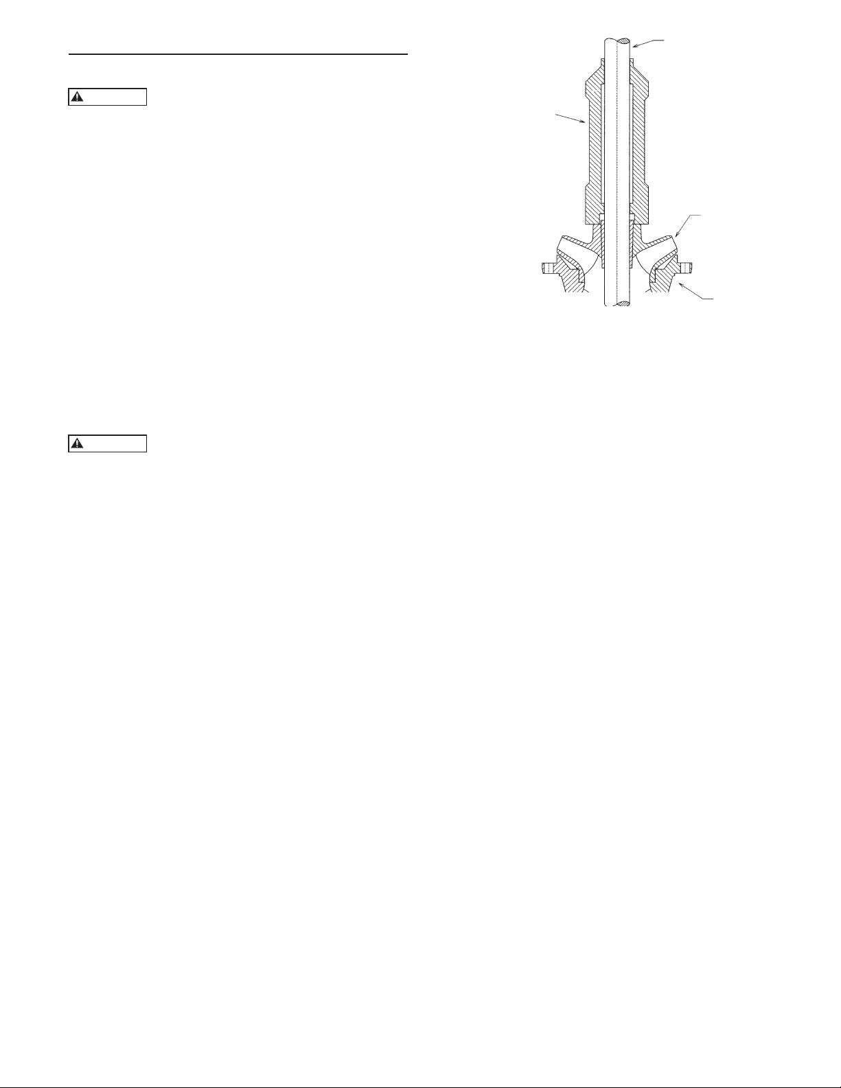
Disassembly And Reassembly – SECTION 6
WARNING
WARNING
DISASSEMBLY
Before working on pump or motor, lock
out driver power to prevent accidental
startup and physical injury.
NOTE: Pump components should be match-marked
prior to disassembly to ensure they are
reassembled in the correct location.
SHAFT
TAPERLOCK DRIVER
DISASSEMBLY POSITION
HEAD AND COLUMN
1. On pumps which are driven through a gear drive,
remove the driveshaft between the gear and the
prime mover.
2. On pumps, which are electric motor driven, remove
the electrical connections at the conduit box and tag
the electrical leads, so they can be reassembled the
same way they were disassembled.
3. Uncouple driver (or gear box) from pump shaft and
mounting flanges and lift off by the lifting lugs or
eyebolts as furnished.
Never try to lift entire pump assembly by
the lifting lugs or eyebolts furnished for the
driver only.
4. Disconnect discharge head from the discharge
piping. Remove all hold down bolts and external
piping. Remove coupling, packing box and proceed
with disassembly down to the bowls by reversing
the procedures described in detail for assembling the
unit.
BOWL ASSEMBLY
The bowl assembly is composed of a suction bowl/bell,
intermediate bowl(s), top bowl, impellers and securing
hardware, bearings, and pump shaft.
Turbine bowl impellers are secured to the shaft by either
a taperlock or a key and split thrust ring. Follow only
those procedures that apply to the particular construction
supplied.
NOTE: Match mark bowl assembly in sequence of
disassembly to aid in the reassembly procedure.
IMPELLER
BOWL
Figure 15
3. Pull shaft out as far as possible and strike impeller
hub by using a taperlock driver or equivalent to
drive the impeller off the taperlock (See Figure 15).
4. After the impeller is freed, insert a screw-driver into
the slot in the taperlock and spread it open. Slide
the taperlock and impeller off the pump shaft.
5. Repeat the above procedures until the bowl
assembly is completely disassembled.
KEYED BOWL DISASSEMBLY
1. Remove capscrews that secure top bowl (669) to
intermediate bowl (670).
2. Slide top bowl off the pumpshaft (660).
3. Remove capscrews (759) and split thrust ring (725)
from pump shaft.
4. Slide impeller off the pumpshaft and remove the
key (730). If impeller is seized to the shaft, strike
impeller with a fiber mallet and drive impeller off
the pumpshaft.
5. Repeat the above procedures until the bowl
assembly is completely disassembled
TURBINE BOWL – WEAR RING REMOVAL
TAPERLOCK CONSTRUCTION BOWL
DISASSEMBLY
1. Remove capscrews that secure top bowl (669), not
shown, to intermediate bowl (670). See Figure 1 or
2.
2. Slide discharge bowl and top bowl off the pump
shaft (660).
1. Remove set screws or grind off tack weld, when
rings are furnished with those locking methods.
2. Utilizing a diamond point chisel, cut two “V” shaped
grooves on the bowl wear ring approximately 180º
apart. Use extreme care not to damage the wear ring
seat.
3. With a chisel or drift, knock the end of one half of
the ring in, and pry the ring out.
4. On special materials such as chrome steel, set up the
bowl in a lathe and machine the wear ring off using
extreme care not to machine or damage the ring
seat.
27

IMPELLER WEAR RING REMOVAL
WARNING
1. Utilizing a diamond point chisel, cut two “V” shaped
grooves on the impeller wear ring approximately
180 degrees apart. Use extreme care not to damage
the wear ring seat.
2. With a chisel or drift, knock the end of one half of
the ring out, and pry the ring off.
3. On special materials such as chrome steel, set up the
impeller in a lathe and machine the wear ring off
using extreme care not to machine or damage the
ring seat.
BOWL AND LINESHAFT BEARING REMOVAL
Utilizing an arbor press and a piece of pipe or sleeve
with outside diameter slightly smaller than the outside
diameter of the bearing to press the bearing out.
NOTE: Bowl bearings are press fit. Do not remove
unless replacement is necessary.
INSPECTION AND REASSEMBLY
INSPECTION AND REPLACEMENT
1. Clean all pump parts thoroughly with a suitable
cleaner.
REASSEMBLY OF THE BOWL ASSEMBLY WITH
TAPERLOCK CONSTRUCTION
1. For ease in re-assembly apply a thin film of turbine
oil to all mating and threaded parts.
2. If the sand collar is not assembled to the shaft,
install the sand collar. The sand collar is attached
to the shaft with a shrink fit. The larger diameter
of the counterbore of the sand collar goes toward
the suction bell bearing. Heat the sand collar until
it slips over the shaft and quickly position it so that
the bottom of the sand collar is set according to the
"X" dimension, before it cools. See Figure 16. See
Table 1 for the "X" dimensions. Slide the plain end
of the pump shaft into the suction bowl/bell bearing
until the sand collar rests against the suction bowl/
bell.
Wear protective gloves and use appropriate eye protection to prevent injury when
handling hot parts.
3. Hold the shaft in this position by inserting a long
capscrew (or all thread rod with a hex nut) with an
assembly jig into the bottom end of the suction hub
and secure tight into the threaded hole at the end
of the shaft. Be sure the shaft has been cleaned and
checked the straightness.
2. Check bearing retainers for deformation and wear.
3. Check shafts for straightness and excessive wear
on bearing surfaces. Average total run-out should
be less than 0.0005” TIR per foot, not to exceed
0.005” T.I.R. for every 10 feet of shafting.
4. Visually check impellers and bowls for cracks and
pitting. Check all bowl bearings for excessive wear
and corrosion.
5. Replace all badly worn or damaged parts with new
parts. In addition, replace all gaskets and packing as
required.
TURBINE BOWL WEAR RING INSTALLATION
Place chamfered face of the bowl or impeller wear ring
towards the ring seat and press the ring into the seat.
Use an arbor press or equal, making sure the ring is flush
with the edge or the wear ring seat.
INSTALL BOWL AND LINESHAFT BEARING
(Refer to Figure 1 for components numbers)
1. Press bearing (656) into retainer (652) using an
arbor press or equal.
Figure 16
2. Press bearing (690) into suction bowl/bell (689) by
using an arbor press or equal. The top of the bearing
should protrude above the suction hub equal to the
depth of the counter bore in the sand collar.
3. Place the bowl (670) with the flange downward and
press bearing (672) through chamfered side of bowl
hub until the bearing is flush with the hub by using
an arbor press or equal.
28
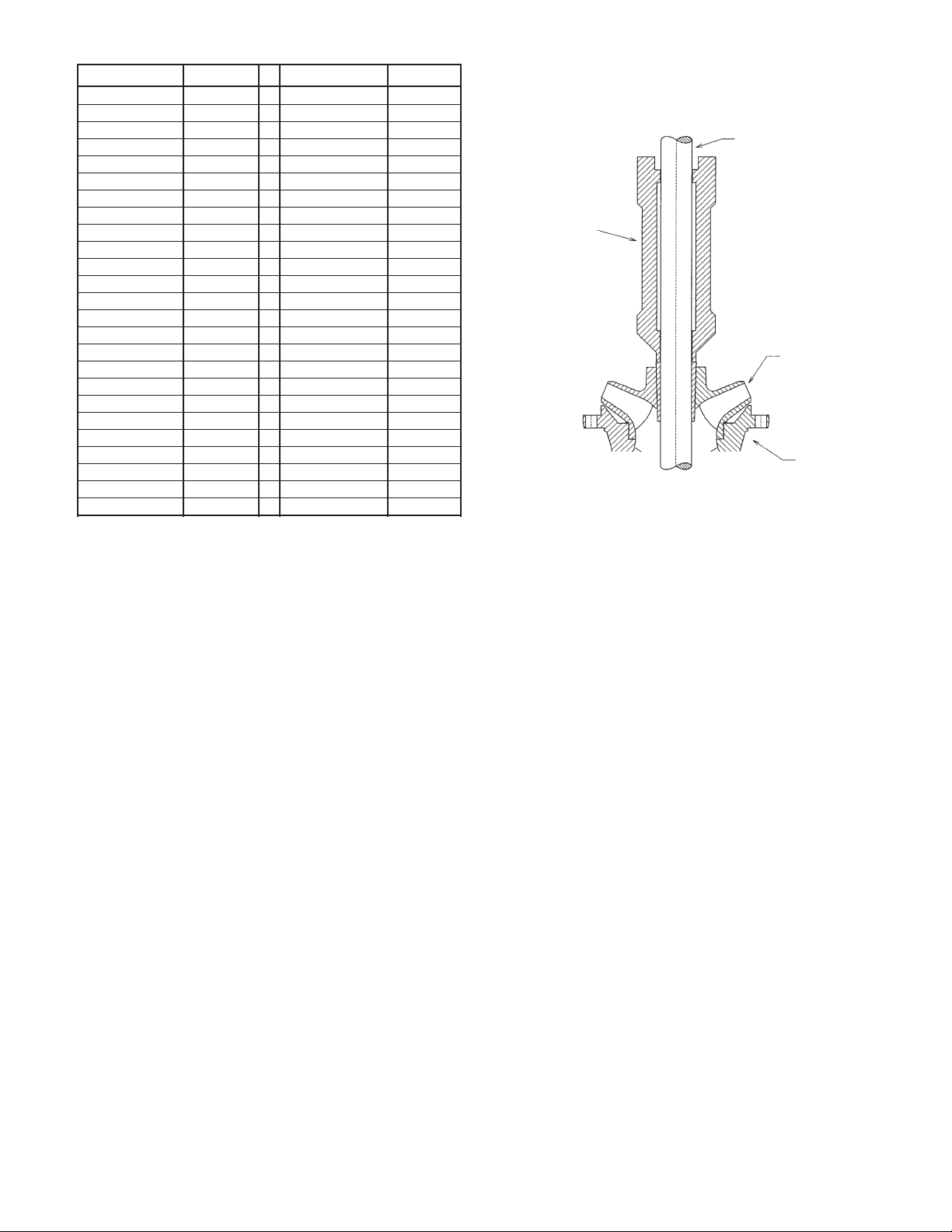
TABLE 1 Sand Collar Location Dimension
Pump Model “X” Dim. Pump Model “X” Dim.
5C, 5T 1.88” 13A, 13RA 7.19”
5WA 1.81” 13C 5.13”
6A, 6RA 3.13” 14DH 8.13”
6C 2.25” 14F, 14H,14RH 7.13”
6DH 3.50” 14RJ 5.06”
7A, 7RA 3.13” 15F Bowl 9.50”
7C, 7T, 7WA 2.81” 16B 6.56”
8A, 8RA 3.13” 16DH Bowl 8.63”
8DH 4.44” 16DM 5.88”
8RJ 2.88” 16RG 6.69”
9A, 9RA 3.41” 18B 7.25”
9RC, 9T, 9WA 5.19” 18C 6.63”
10A, 10RA 4.31” 18D 7.56”
10DH 6.31” 18GX 5.75”
10L 6.25” 20B, 18L 6.88”
10RJ 5.00” 20E,18H 7.00”
10WA 5.19” 20C 6.44”
11A, 11RA 5.31” 24C 12.38”
11C 4.88” 24D 9.38”
11WA 5.13” 24E 8.13”
12C 5.31” 24F 10.44”
12FD 5.19” 24G 8.00”
12FR 6.50” 26G 7.75”
12WA, 12RA 5.00” 28G 8.75”
12RJ 4.94” 30B NA
FINAL ASSEMBLY
After assembly of bowl assembly, reassemble pump as
described in Section 3, Installation. Refer to Section 4,
for startup and operation procedures.
SHAFT
TAPERLOCK
DRIVER
DISASSEMBLY
POSITION
IMPELLER
BOWL
Figure 17
4. Slide the first impeller over the shaft until it seats on
the suction bowl/bell.
NOTE: If there are different diameter impellers, put the
large diameter impeller at the lower stage.
5. Insert a screwdriver into the slot in the taperlock
(677) to spread the slot and slide the taperlock over
the pump shaft. Hold the impeller against bowl and
slide the taperlock into the impeller hub. Be sure the
taperlocks have been cleaned and are dry.
6. Hold impeller firmly against the suction bowl/bell
and drive the taperlock into place with a taperlock
driver, (See Figure 17). After the impeller is secured
in position, the top end of the taperlock should be
1/8” above the impeller hub.
7. Slide intermediate bowl (670) onto shaft and secure
with capscrews provided.
8. Repeat preceding procedure for number of stages
required.
9. Remove long capscrew and the assembly jig at the
end of suction hub and check that the shaft rotates
freely without dragging or binding. Also check for
adequate lateral (end play).
29

Repair Parts – SECTION 7
CAUTION
ORDERING PARTS
When ordering spare or replacement parts, the pump
serial number and size and type of pump must be given.
This can be found on the nameplate furnished with the
unit. Give the complete name and reference number
of each part as indicated on the applicable sectional
drawings, Figure 1 or Figure 2, and the quantity
required.
STOCKING SPARE PARTS
Spare parts to be kept in inventory will vary according
to service, field maintenance, allowable down time and
number of units. A minimum inventory of one complete
set of bearings and one spare of each moving part is
suggested.
RETURNING PARTS
A completed Return Material Authorization (RMA)
form must accompany all materials returned to the
factory. The RMA forms can be obtained direct
from the factory or through your local Goulds Water
Technology representative. The RMA form must be
filled in completely and forwarded as directed thereon.
Parts being returned under warranty claim must have a
complete written report submitted with the RMA form.
Returned material must be carefully
packaged to prevent transit damage the factory cannot assume any responsibility for parts
damaged in transit.
30

Notes
31

Company warrants title to the product(s) and, except as noted with respect to items not of Company’s manufacturer, also warrants the
LIMITED WARRANTY
product(s) on date of shipment to Purchaser, to be of the kind and quality described herein, and free of defects in workmanship and
material. THIS WARRANTY IS EXPRESSLY IN LIEU OF ALL OTHER WARRANTIES, INCLUDING BUT NOT LIMITED TO IMPLIED
WARRANTIES OF MERCHANTABILITY AND FITNESS, AND CONSTITUTES THE ONLY WARRANTY OF COMPANY WITH RESPECT
TO THE PRODUCT(S).
If within one year from date of initial operation, but not more than 18 months from date of shipment by Company of any item of product(s),
Purchaser discovers that such item was not as warranted above and promptly notifies Company in writing thereof, Company shall remedy such
nonconformance by, at Company’s option, adjustment or repair or replacement of the item and any affected part of the product(s). Purchaser
shall assume all responsibility and expense for removal, reinstallation, and freight in connection with the foregoing remedies. The same
obligations and conditions shall extend to replacement parts furnished by Company hereunder. Company shall have the right of disposal of parts
replaced by it. Purchaser agrees to notify Company, in writing, of any apparent defects in design, material or workmanship, prior to performing
any corrective action back-chargeable to the Company. Purchaser shall provide a detailed estimate for approval by the Company.
ANY SEPARATE LISTED ITEM OF THE PRODUCT(S) WHICH IS NOT MANUFACTURED BY THE COMPANY IS NOT WARRANTED BY
COMPANY and shall be covered only by the express warranty, if any, of the manufacturer thereof.
THIS STATES THE PURCHASER’S EXCLUSIVE REMEDY AGAINST THE COMPANY AND ITS SUPPLIERS RELATING TO THE
PRODUCT(S), WHETHER IN CONTRACT OR IN TORT OR UNDER ANY OTHER LEGAL THEORY, AND WHETHER ARISING
OUT OF WARRANTIES, REPRESENTATIONS, INSTRUCTIONS, INSTALLATIONS OR DEFECTS FROM ANY CAUSE. Company and
its suppliers shall have no obligation as to any products which have been improperly stored or handled, or which have not been operated or
maintained according to instructions in Company or supplier furnished manuals.
LIMITATION OF LIABILITY – Neither Company nor its suppliers shall be liable, whether in contract or in tort or under any other legal
theory, for loss of use, revenue or profit, or cost of capital or of consequential damages, or for any other loss or cost of similar type or for claims
by Purchaser for damages of Purchaser’s customers. Likewise, Company shall not under any circumstances be liable for the fault, negligence,
wrongful acts of Purchaser or Purchaser’s employees, or Purchaser other contractors or suppliers.
IN NO EVENT SHALL COMPANY BE LIABLE IN EXCESS OF THE SALES PRICE OF THE PART OR PRODUCT FOUND DEFECTIVE.
32
Xylem Inc.
PO Box 5487
Lubbock, TX 79408
Phone: 1-806-763-7867
Fax: 1-800-453-4749
www.xyleminc.com/brands/gouldswatertechnology
Goulds is a registered trademark of Goulds Pumps, Inc. and is used under license.
© 2013 Xylem Inc. IMVICR01 April 2013
 Loading...