

Page 1
ITT
Goulds Pumps
G&L SERIES
MODEL SVI
Installation, Operation and
Maintainence Instructions
General Industry
Goulds Pumps is a brand of ITT Water Technology, Inc.
- a subsidiary of ITT Industries, Inc.
www.goulds.com
Engineered for life
Page 2
SUBJECT PAGE
SVI Product Line Numbering System .............................................................................................................................3
Safety Instructions .........................................................................................................................................................5
Installation ....................................................................................................................................................................5
Piping ............................................................................................................................................................................5
Shaft Alignment – Motor to Pump .................................................................................................................................5
Wiring and Grounding ..................................................................................................................................................6
Operation ......................................................................................................................................................................6
Maintenance..................................................................................................................................................................6
Disassembly/Assembly
Mechanical Seal Replacement ......................................................................................................................................7
Motor Replacement .....................................................................................................................................................7
Troubleshooting ............................................................................................................................................................8
Engineering Data ...........................................................................................................................................................8
Motor Data ...................................................................................................................................................................8
SVI Sectional Assembly ................................................................................................................................................10
Limited Warranty ........................................................................................................................................................13
Declaration of Conformity ..........................................................................................................................................33
Pump Model Number:
Pump Serial Number:
Control Model Number:
Dealer:
Dealer Phone No.:
Date of Purchase: Installation:
Current Readings at Startup:
1 Ø 3 Ø L1-2 L2-3 L3-1
Amps: Amps:
Volts: Volts:
SERIES — SÉRIE — SERIES
1SV 3SV
2SV 4SV
2
Page 3
SVI PRODUCT LINE NUMBERING SYSTEM
COMPLETE PUMPS
2 SV N 1 G 11 F H E 5 EXAMPLE PRODUCT CODE*
➤
Seal Options:
0 = Standard Silicon Carbide/Carbon/Viton
4 = Silicon Carbide/Silicon Carbide/Viton
5 = Tungsten Carbide/Tungsten Carbide/Viton
Discharge Connection:
E = NPT M = BSP A = Flanged ANSI Drilling D = Flanged DIN Drilling
Bowls:
A = 1 E = 5 J = 9 N = 13
B = 2 F = 6 K = 10 P = 14
C = 3 G = 7 L = 11 Q = 15
D = 4 H = 8 M = 12 R = 16
Impellers:
A = 1 E = 5 J = 9 N = 13
B = 2 F = 6 K = 10 P = 14
C = 3 G = 7 L = 11 Q = 15
D = 4 H = 8 M = 12 R = 16
Driver:
01 = 1PH, ODP, NEMA 07 = 3PH, XP, NEMA 13 = 3PH, 575V, TEFC, NEMA, MF**
02 = 3PH, ODP, NEMA 08 = 575V, XP, NEMA 14 = 1PH, 230V, TEFC, NEMA, MF**
03 = 575V, ODP, NEMA 09 = 3PH, TEFC, PE, NEMA 15 = 3PH, 220-255/380-440, IEC
04 = 1PH, TEFC, NEMA 10 = 1PH, XP, NEMA 16 = 3PH, 265-277/460-480, IEC
05 = 3PH, TEFC, NEMA 11 = 3PH, 200V, TE, NEMA, MF**
06 = 575V, TEFC, NEMA 12 = 3PH, 208-230/460V, TE, NEMA, MF**
**MF = Metric Flange
* Not all combinations are available.
HP Rating:
C = ½ F = 1½ J = 5 M = 15 Q = 30
D = ¾ G = 2 K = 7½ N = 20
E = 1 H = 3 L = 10 P = 25
Hertz/RPM:
1 = 60 Hz/3500 RPM
2 = 50 Hz/2900 RPM
Version:
S = CI/NEMA Motor Adapter
X = CI/IEC Motor Adapter
N = Stainless Steel/IEC Motor Adapter
Product Line: Stainless Vertical Immersed
Nominal Flow:
1 = 15 GPM 3 = 55 GPM
2 = 28 GPM 4 = 86 GPM
3
Page 4

SVI PRODUCT LINE NUMBERING SYSTEM
LIQUID ENDS
2 SV N K F H E 5 T EXAMPLE PRODUCT CODE
➤
Optional Suffix:
T = Next Size Larger Motor Frame
Seal Options:
0 = Standard Silicon Carbide/Carbon/Viton
4 = Silicon Carbide/Silicon Carbide/Viton
5 = Tungsten Carbide/Tungsten Carbide/Viton
Discharge Connection:
E = NPT M = BSP
Bowls:
A = 1 E = 5 J = 9 N = 13
B = 2 F = 6 K = 10 P = 14
C = 3 G = 7 L = 11 Q = 15
D = 4 H = 8 M = 12 R = 16
Impellers:
A = 1 E = 5 J = 9 N = 13
B = 2 F = 6 K = 10 P = 14
C = 3 G = 7 L = 11 Q = 15
D = 4 H = 8 M = 12 R = 16
Liquid End:
Version:
S = CI/NEMA Motor Adapter
X = CI/IEC Motor Adapter
N = Stainless Steel/IEC Motor Adapter
Product Line: Stainless Vertical Immersed
Nominal Flow:
1 = 15 GPM 3 = 55 GPM
2 = 28 GPM 4 = 86 GPM
4
Page 5
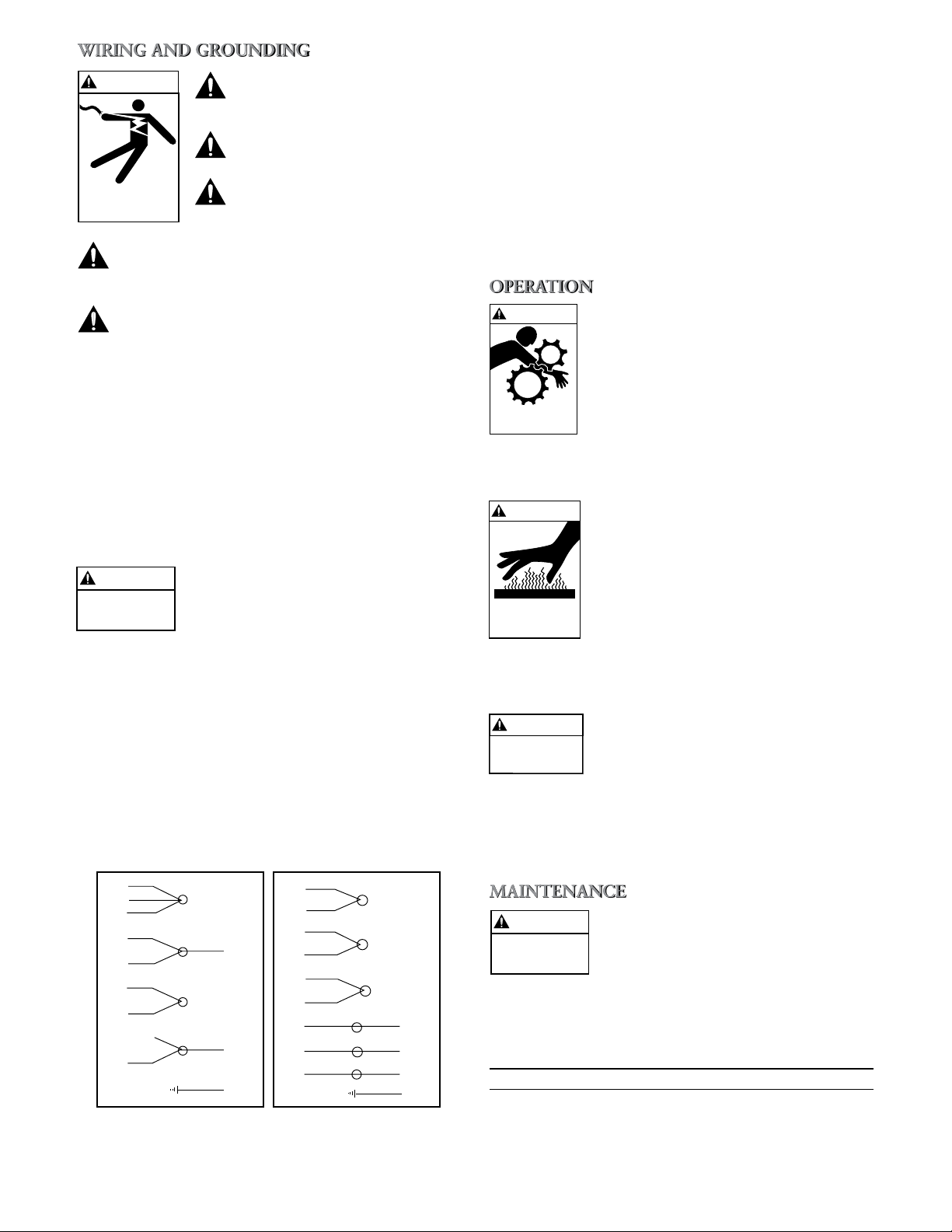
DANGER
WARNING
CAUTION
WARNING
Hazardous fluids
can cause fire,
burns or death.
SAFETY INSTRUCTIONS
TO AVOID SERIOUS OR FATAL PERSONAL INJURY
OR MAJOR PROPERTY DAMAGE, READ AND
FOLLOW ALL SAFETY INSTRUCTIONS IN MANUAL
AND ON PUMP.
THIS MANUAL IS INTENDED TO ASSIST IN THE
INSTALLATION AND OPERATION OF THIS UNIT
AND MUST BE KEPT WITH THE PUMP.
This is a SAFETY ALERT SYMBOL.
When you see this symbol on the pump
or in the manual, look for one of the
following signal words and be alert
to the potential for personal injury or
property damage.
Warns of hazards that WILL cause
serious personal injury, death or major
property damage.
Warns of hazards that CAN cause
serious personal injury, death or major
property damage.
Warns of hazards that CAN cause personal injury or property damage.
NOTICE: INDICATES SPECIAL INSTRUCTIONS
WHICH ARE VERY IMPORTANT AND
MUST BE FOLLOWED.
THOROUGHLY REVIEW ALL INSTRUCTIONS
AND WARNINGS PRIOR TO PERFORMING ANY
WORK ON THIS PUMP.
MAINTAIN ALL SAFETY DECALS.
UNIT NOT DESIGNED FOR USE
WITH HAZARDOUS LIQUIDS OR
FLAMMABLE GASES. THESE
FLUIDS MAY BE PRESENT IN
CONTAINMENT AREAS.
Provide adequate space and ventilation around unit for
•
service and for motor cooling.
Protect the pump and piping from freezing tempera-
•
tures.
The unit MUST be securely affixed to a level metal
•
base foundation, adequate to absorb vibration and provide permanent, rigid support for the pump and motor
assembly. See the “ENGINEERING DATA” section of
this manual for specific model weights and pump base
dimensions.
NOTICE: DO NOT DRAW PIPING INTO PLACE BY
FORCING THE PUMP DISCHARGE
CONNECTIONS.
Discharge piping should be no smaller than the
•
respective pump opening and should be kept as short
as possible, avoiding unnecessary fittings to minimize
friction losses.
NOTICE: PIPING MUST BE INDEPENDENTLY SUP-
PORTED AND NOT PLACE ANY PIPING
LOADS ON THE PUMP.
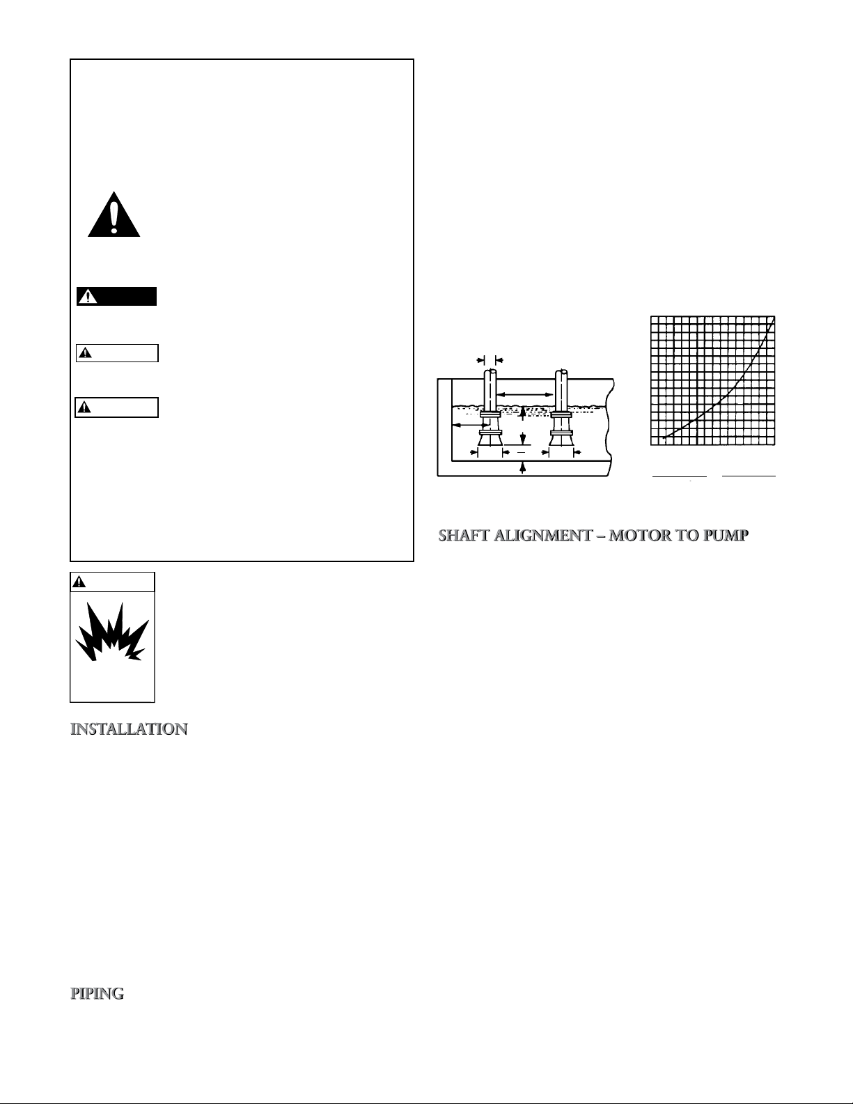
Insure that the size and minimum liquid submergence,
•
over the suction inlet, is sufficient to prevent air from
entering through a suction vortex. See typical suction
piping Figures 1 and 2.
Install a discharge check valve, suitable to handle the
•
flow and liquids, to prevent backflow.
Install an appropriately sized gate valve, AFTER the
•
discharge valve, to regulate the pump capacity, for
pump inspection and for maintenance.
When a pipe increaser is required, install between the
•
check valve and the pump discharge.
H
16
15
14
13
12
11
10
9
8
7
6
5
4
3
2
H = Min. Submergence in feet
1
0
1 2 3 4 5 6 7 8 9 10 11 12 13 14 15 16 V
V = Velocity in feet per second
=GPM x 0.321
Area
GPM x 0.4085
2
D
4D
min.
D
8D
min.
H min.
min.
3D
3D
3D
2
Figure 1 Figure 2
When the pump is purchased less motor, the pump will
•
be supplied with a motor assembly shim positioned
between the motor adapter and the coupling.
To assemble the motor to the pump remove the plastic
•
shipping straps, the 2 stainless steel coupling guard
halves, and the expanded polyurethane.
Insure that the motor assembly shim is properly posi-
•
tioned between the coupling and the motor adapter. If
the motor assembly shim is not available, a 0.203"
(5 mm) shim may be used to locate the pump shaft
assembly and to set the correct height.
For motor frame sizes 213TC and larger, attach the
•
motor adapter flange to the motor using 4 hex cap
screws. Torque to values shown in the
“ENGINEERING DATA” section of this manual.
Loosen the 4 coupling socket head screws enough to
•
provide an adequate opening in the coupling to receive
the motor shaft.
With an adequately sized crane, carefully lower the
•
motor assembly onto the pump motor adapter and
into the coupling. Secure the 4 motor hex cap screws,
torquing to the value provided in the
“ENGINEERING DATA” section of this manual.
Torque the 4 coupling socket head screws to the value
•
provided in “ENGINEERING DATA” section of this
manual.
Remove the motor assembly shim and retain for future
•
use.
Install the 2 coupling guard halves.
•
5
Page 6
Install, ground and wire
WARNING
Hazardous voltage
can shock, burn or
cause death.
WARNING
Hazardous
voltage
208-230V 3/60 460V 3/60
4
5
6
1
7
2
8
3
9
L
1
L
2
L
3
4
7
5
8
6
9
1
2
3
L
1
L
2
L
3
G
G
MOTOR LEADS
MOTOR LEADS
POWER CABLE LEADS
POWER CABLE LEADS
THREE PHASE MOTOR WIRING DIAGRAM
WARNING
Hazardous machinery
can cause personal
injury or death.
WARNING
Extreme heat can
cause personal injury
or property damage
WARNING
Hazardous
machinery
WARNING
Hazardous
voltage
according to local and National
Electrical Code requirements.
Install an all leg disconnect
switch near pump.
Disconnect and lockout electrical power before installing or
servicing pump.
Electrical supply MUST match pump’s nameplate
specifications. Incorrect voltage can cause fire,
damage motor and voids warranty.
NOTICE: UNIT ROTATION IS CLOCKWISE WHEN
VIEWED FROM MOTOR END.
INCORRECT ROTATION MAY CAUSE
DAMAGE TO THE PUMP AND VOIDS
WARRANTY.
Check pump rotation by observing the motor fan or
•
the coupling THROUGH the coupling guard. DO
NOT confuse the flow arrows, stamped on the pump
body, with the rotation arrows on the coupling and
motor adapter. Three phase motors only – If rotation is
incorrect, have a qualified electrician interchange any
two of the three power cable leads.
Motors equipped with automatic thermal protectors open the motor’s electrical circuit when an
overload exists. This can cause the pump to start
unexpectedly and without warning.
Use only stranded copper wire to motor and ground.
•
Wire size MUST limit the maximum voltage drop to
10% of the motor nameplate voltage, at the motor terminals. Excessive voltage drop will affect performance
and void motor warranty. The ground wire must be at
least as large as the wires to the motor. Wires should be
color coded for ease of maintenance.
Three phase motors require all leg protection with
•
properly sized magnetic starters and thermal overloads.
PERMANENTLY GROUND THE
PUMP, MOTOR AND CONTROLS
PER NEC OR LOCAL CODES BEFORE CONNECTING TO ELECTRICAL POWER. FAILURE TO DO SO
CAN CAUSE SHOCK, BURNS OR
DEATH.
Connect the electrical leads to the motor, as follows:
•
Single Phase Motors – Connect the BLACK wire to the
•
BLACK motor wire. Connect the WHITE wire to the
WHITE motor wire. Connect the GREEN wire to the
GREEN motor wire.
Three Phase Motors – See Figure 3.
•
DO NOT OPERATE UNIT WITHOUT SAFETY GUARD IN PLACE.
TO DO SO CAN CAUSE SEVERE
PERSONAL INJURY.
NOTICE: PUMP MUST BE COMPLETELY PRIMED
BEFORE OPERATION.
DO NOT OPERATE PUMP AT OR
NEAR ZERO FLOW. TO DO SO CAN
CAUSE EXTREME HEAT, DAMAGE
TO THE PUMP, INJURY OR PROPERTY DAMAGE.
After stabilizing the system at normal operating condi-
•
tions, check piping for correct alignments. If necessary,
adjust pipe supports.
MOTOR THERMAL PROTECTORS
CAN RESTART MOTOR UNEXPECTEDLY AND WITHOUT WARNING, CAUSING SEVERE PERSONAL
INJURY.
See the “ENGINEERING DATA” section in this
•
manual for the recommended maximum pump starts
per hour.
6
Figure 3
DISCONNECT AND LOCKOUT
ELECTRICAL POWER BEFORE
ATTEMPTING ANY MAINTENANCE. FAILURE TO DO SO CAN
CAUSE SHOCK, BURNS OR DEATH.
Unit motor requires regular lubrication maintenance.
•
MOTOR LUBRICATION
Recommended Motor Bearing Lubrication Intervals
Interval Service Environment
1 – 2 Years Light Duty in Clean Atmosphere
1 Year 8 – 16 hours/day – Clean, Dry Atmosphere
6 Months 12 – 24 hours/day – Moisture Present
3 Months 12 – 24 hours/day – Dirty, High Moisture
Page 7

When lubricants are operated at elevated temperatures,
•
the lubrication frequency should be increased.
DO NOT intermix grease bases (lithium, sodium, etc.).
•
Completely purge old grease if changing grease base.
Over greasing can cause excessive bearing tempera-
•
tures, lubricant and bearing failure.
1. Close all necessary suction and discharge valves.
2. Remove the coupling guards, the 4 coupling hex cap
screws, the coupling and coupling drive pin.
3. Remove pump and drain.
4. Remove the 4 motor hex cap screws. On units with
motor frames 213TC and larger, remove the 4 motor
adapter flange hex cap screws. With an adequately
sized crane, carefully remove the motor. DO NOT
rest the motor on the motor shaft.
5. Remove the 4 tie rod nuts and lock washers.
6. Carefully remove the suction bottom and strainer.
Larger units may require an adequately sized crane to
lift the motor adapter. DO NOT damage the shaft.
NOTICE: EDGES OF THE STAINLESS STEEL PARTS
ARE SHARP. WEAR APPROPRIATE PROTECTIVE CLOTHING.
7. Remove the stack and casing.
8. Slide the mechanical seal rotary element, spring and
washer from the pump shaft.
9. Remove the seal stationary element from the pump
discharge head. Discard the entire seal assembly.
10. Lubricate the inside of the new mechanical seal as-
sembly with a quality grade of glycerin.
11. Lubricate the outside of the new mechanical seal sta-
tionary element with a quality grade of glycerin.
12. Insert the stationary seat into the discharge head
with the seal face out. DO NOT scratch or otherwise
damage the seal face. Insure that the stationary seat
is fully seated into the seal housing. With a clean, lint
free cloth, wipe the seal face clean of all lubricant or
debris.
13. To install a new mechanical seal rotary assembly, slide
the assembly onto the pump shaft, spring end first.
Be sure the top spring tip is in the hole of the rotary
portion of the seal. DO NOT scratch or otherwise
damage the seal face. With a clean, lint free cloth,
wipe the seal face clean of all lubricant or debris.
14. Carefully replace the impellers, spacers, bowls and
casing in the reverse order.
15. Install the base and strainer. Tighten the tie rod nuts
and torque to the value provided in the
“ENGINEERING DATA” section of this manual.
16. With an adequately sized crane, carefully lower the
motor onto the motor adapter, lining up the electrical conduit connection and the 4 motor adapter bolt
holes, as required.
17. Install the 4 motor hex cap screws, torquing to the
value provided in the “ENGINEERING DATA”
section of this manual.
18. Place the coupling drive pin into the pump shaft and
install the coupling halves onto the motor and pump
shafts. Install the 4 coupling socket head screws, lock
washers and nuts, DO NOT tighten.
19. Position the motor assembly shim between the coupling and the motor adapter. If the motor assembly
shim is not available, a 0.203" (5 mm) shim may be
used to locate the pump shaft assembly and to set the
correct height.
20. Tighten the 4 coupling socket head screws, torquing
screws to values provided in the “ENGINEERING
DATA” section of this manual. Tighten evenly so that
the gap between the halves is equal side to side and
top to bottom.
21. Install the 2 coupling guard halves.
To remove the motor follow steps 1 through 4, as
•
provided in the “MECHANICAL SEAL REPLACE-
MENT” section of this manual.
For motor frames 213TC and larger, remove the 4 mo-
•
tor hex cap screws and the motor adapter.
Install the motor adapter flange onto the new motor,
•
torquing the 4 hex cap screws to the values provided in
the “ENGINEERING DATA” section of this manual.
Complete the reassembly following steps 16 through
•
21 in the “MECHANICAL SEAL REPLACEMENT”
section of this manual.
• All additional unit service or maintenance, not
addressed in this manual, should be performed at a
qualified service location. Contact your local dealer or
G&L Pumps distributor for assistance.
7
Page 8
DISCONNECT AND LOCKOUT
WARNING
Hazardous
voltage
ELECTRICAL POWER BEFORE ATTEMPTING ANY MAINTENANCE.
FAILURE TO DO SO CAN CAUSE
SHOCK, BURNS OR DEATH.
SYMPTOM
MOTOR NOT RUNNING
See Probable Cause – 1 through 5
LITTLE OR NO LIQUID DELIVERED BY PUMP
See Probable Cause – 6 through 12
POWER CONSUMPTION TOO HIGH
See Probable Cause – 3, 12, 13, 15
EXCESSIVE NOISE AND VIBRATION
See Probable Cause – 3, 6 - 8, 10, 12, 13, 16
PROBABLE CAUSE
1. Motor thermal protector tripped.
2. Open circuit breaker or blown fuse.
3. Impellers binding.
4. Motor improperly wired.
5. Defective motor.
6. Pump is not primed, air or gases in liquid.
7. Discharge, suction plugged or valve closed.
8. Incorrect rotation (three phase only).
9. Low voltage or phase loss.
10. Impellers worn or plugged.
11. System head too high.
12. NPSHA too low – excessive suction lift or losses.
13. Discharge head too low – excessive flow rate.
14. Fluid viscosity, specific gravity too high.
15. Worn bearing.
16. Pump, motor or piping loose.
Maximum Working Pressure =
(1SV, 2SV, 3SV, 4SV)
230 psi (16 bar) with the oval suction and
discharge flanges
360 psi (25 bar) with ANSI suction and
discharge flanges
Maximum Liquid Temperature =
230º F (110º C)
STARTS PER HOUR / MINIMUM RUN TIME – 3 Phase Only
HP Maximum Starts Per Hour Minimum Run Time Between
(evenly distributed) Starts (seconds)
1 15 75
1.5 13 76
2 12 77
3 9 80
5 8 83
7.5 7 88
10 6 92
15 5 100
20 5 110
25 5 115
30 4 120
40 4 130
50 3 145
60 3 170
75 3 180
NOTE(S)
1) Recommended motor starts per hour and minimum run time calculated based on
NEMA standards MG1-12.44 in accordance to manufacturers allowable tolerance
for heat rise and insulation breakdown.
2) Applied voltage and frequency in accordance with NEMA MG1-12.44
3) Starts based on NEMA three phase design A and design B AC induction motors.
4) External load WK2 is equal to or less than the values listed in NEMA MG1-12.54
5) Applicable to all NEMA JM, JP, T and TC frame motors used for Goulds Pumps
products.
6) SINGLE PHASE starts and run time depend on many factors (e.g. capacitor size/
type, wire size and length, switch type) and will not be the same as three phase
motors.
8
Page 9

3500 RPM
HP Phase Enclosure Nameplate Voltage Frame Goulds PN
TEFC 115/230 56C V04722
½ ODP 230/460 56C V04741
3 TEFC 230/460 56C V04742
X-PROOF 230/460 56C V04743
TEFC 115/230 56C V05722
¾
X-PROOF 230/460 56C V05743
PREMIUM EFFICIENCY TEFC 230/460 56C V05742PE
TEFC 115/230 56C V06722
1
X-PROOF 230/460 56C V06743
PREMIUM EFFICIENCY TEFC 230/460 56C V06742PE
TEFC 115/230 56C V07722
ODP 230/460 56C V07741
1½
3 X-PROOF 230/460 56C V07743
PREMIUM EFFICIENCY ODP 230/460 56C V07741PE
PREMIUM EFFICIENCY TEFC 230/460 56C V07742PE
TEFC 115/230 56C V08722
ODP 208-230/460 56C V08741
2 TEFC 208-230/460 56C V08742
3 X-PROOF 208-230/460 56C V08743
PREMIUM EFFICIENCY ODP 208-230/460 56C V08741PE
PREMIUM EFFICIENCY TEFC 208-230/460 56C V08742PE
TEFC 115/230 56C V09722
ODP 208-230/460 56C V09741
3 TEFC 208-230/460 56C V09742
3 X-PROOF 208-230/460 56C V09743
PREMIUM EFFICIENCY ODP 208-230/460 56C V09741PE
PREMIUM EFFICIENCY TEFC 208-230/460 184TCH V09742PE
TEFC 208-230 184TCH V10722
ODP 208-230/460 184TCH V10741
5 TEFC 208-230/460 184TCH V10742
3 X-PROOF 230/460 184TCH V10743
PREMIUM EFFICIENCY ODP 208-230/460 184TCH V10741PE
PREMIUM EFFICIENCY TEFC 208-230/460 184TCH V10742PE
TEFC 230 213TC V11722
ODP 208-230/460 184TCH V11741
7½ TEFC 208-230/460 184TCH V11742
3 X-PROOF 230/460 184TCH V11743
PREMIUM EFFICIENCY ODP 208-230/460 184TCH V11741PE
PREMIUM EFFICIENCY TEFC 230/460 213TC V11742APE
TEFC 230 213TC V12722
ODP 208-230/460 213TC V12741
10 TEFC 208-230/460 215TC V12742
3 X-PROOF 230/460 215TC V12743
PREMIUM EFFICIENCY ODP 208-230/460 213TC V12741PE
PREMIUM EFFICIENCY TEFC 230/460 215TC V12742PE
ODP 208-230/460 215TC V13741
TEFC 208-230/460 254TC V13742
15 3 X-PROOF 230/460 254TC V13743
PREMIUM EFFICIENCY ODP 208-230/460 215TC V13741PE
PREMIUM EFFICIENCY TEFC 208-230/460 254TC V13742PE
ODP 230/460 254TC V14741
TEFC 208-230/460 256TC V14742
20 3 X-PROOF 230/460 256TC V14743
PREMIUM EFFICIENCY ODP 208-230/460 254TC V14741PE
PREMIUM EFFICIENCY TEFC 208-230/460 256TC V14742PE
ODP 115/230 56C V04721
1
1
3
1
3
1
1
1
1
1
1
ODP 115/230 56C V05721
ODP 230/460 56C V05741
TEFC 230/460 56C V05742
ODP 115/230 56C V06721
ODP 230/460 56C V06741
TEFC 230/460 56C V06742
ODP 115/230 56C V07721
TEFC 230/460 56C V07742
ODP 115/230 56C V08721
ODP 230 56C V09721
ODP 208-230 184TCH V10721
ODP 230 213TC V11721
ODP 230 213TC V12721
9
Page 10
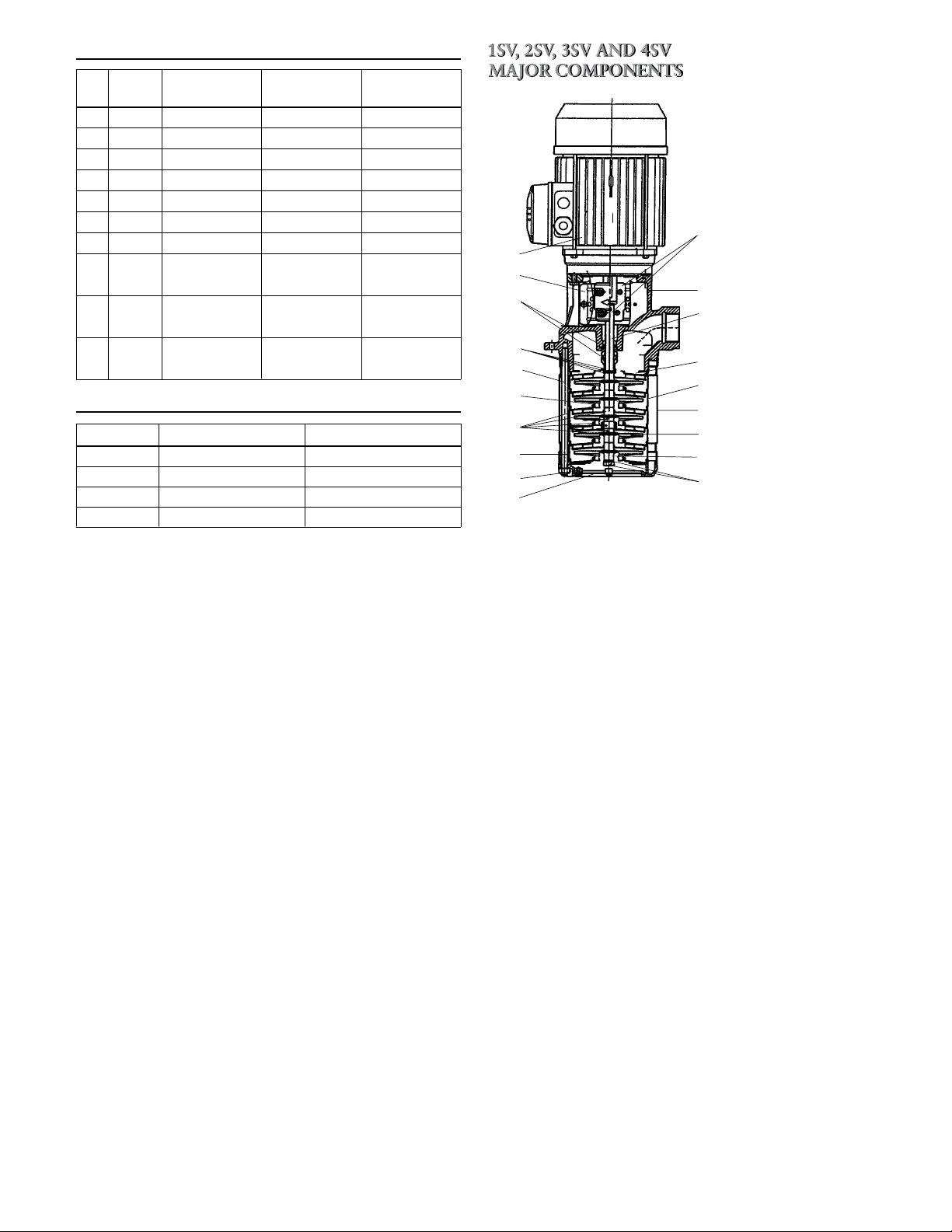
TORQUE VALUES
1
4
2
7
10
11
8
16
17
3
13
18
5
15
12
14
6
9
15
Motor
HP
¾ 56C 20 lbs ft (27 N .m) – 15 lbs ft (20 N .m)
1 56C 20 lbs ft (27 N .m) – 15 lbs ft (20 N .m)
1½ 56C 20 lbs ft (27 N .m) – 15 lbs ft (20 N .m)
2 56C 20 lbs ft (27 N .m) – 15 lbs ft (20 N .m)
3 56C 20 lbs ft (27 N .m) – 15 lbs ft (20 N .m)
5 184TCH 20 lbs ft (27 N .m) – 15 lbs ft (20 N .m)
7½ 184TCH 20 lbs ft (27 N .m) – 15 lbs ft (20 N .m)
10 213TC
215TC
15 215TC
254 TC 48 lbs ft (65 N .m) 48 lbs ft (65 N .m)
20 254TC
256TC
Frame
Motor Bolt Adapter Flange Coupling
45 lbs ft (61 N .m) 30 lbs ft (40 N .m) 30 lbs ft (40 N .m)
45 lbs ft (61 N .m)
45 lbs ft (61 N .m) 48 lbs ft (65 N .m) 48 lbs ft (65 N .m
30 lbs ft (40 N .m) 30 lbs ft (40 N .m)
TORQUE VALUES
Pump Size Tie Rod Nuts Vent and Drain
1SV 22 lbs ft (30 N .m) 15 lbs ft (20 N .m)
2SV 22 lbs ft (30 N .m) 15 lbs ft (20 N .m)
3SV 37 lbs ft (50 N .m) 15 lbs ft (20 N .m)
4SV 37 lbs ft (50 N .m) 15 lbs ft (20 N .m)
1 Motor adapter/discharge
2 Suction bottom cover
3 Sleeve
4 Strainer
5 Diffuser
6 First stage box
7 Diffuser with bush kit
8 Last stage diffuser
9 Impeller
10 Shaft
11 Coupling guard
12 Coupling
)
13 Mechanical seal
14 Tie rod and nut
15 Impeller bolt
16 O-ring
17 Impeller spacer
18 Motor
10
Page 11
ITT
General Industry
GOULDS PUMPS LIMITED WARRANTY
This warranty applies to all water systems pumps manufactured by Goulds Pumps.
Any part or parts found to be defective within the warranty period shall be replaced at no charge to the dealer during the warranty period. The
warranty period shall exist for a period of twelve (12) months from date of installation or eighteen (18) months from date of manufacture, which
ever period is shorter.
A dealer who believes that a warranty claim exists must contact the authorized Goulds Pumps distributor from whom the pump was purchased
and furnish complete details regarding the claim. The distributor is authorized to adjust any warranty claims utilizing the Goulds Pumps Customer
Service Department.
The warranty excludes:
(a) Labor, transportation and related costs incurred by the dealer;
(b) Reinstallation costs of repaired equipment;
(c) Reinstallation costs of replacement equipment;
(d) Consequential damages of any kind; and,
(e) Reimbursement for loss caused by interruption of service.
For purposes of this warranty, the following terms have these definitions:
(1) “Distributor” means any individual, partnership, corporation, association, or other legal relationship that stands between Goulds Pumps and
the dealer in purchases, consignments or contracts for sale of the subject pumps.
(2) “Dealer” means any individual, partnership, corporation, association, or other legal relationship which engages in the business of selling or
leasing pumps to customers.
(3) “Customer” means any entity who buys or leases the subject pumps from a dealer. The “customer” may mean an individual, partnership,
corporation, limited liability company, association or other legal entity which may engage in any type of business.
THIS WARRANTY EXTENDS TO THE DEALER ONLY.
-
Goulds Pumps, G&L and the ITT Engineered Blocks Symbol
are registered trademarks and tradenames of ITT Industries Inc.
SPECIFICATIONS ARE SUBJECT TO CHANGE WITHOUT NOTICE.
IM170R02 March, 2006
© 2006 ITT Water Technology, Inc.
Engineered for life
11
Page 12

ITT
Goulds Pumps
MODÈLE SVI,
SÉRIE G&L
Directives d’installation,
d’utilisation et d’entretien
Industrie
12
Goulds Pumps est une marque d’ITT Water Technology, Inc., une filiale d’ITT Industries, Inc.
www.goulds.com
Engineered for life
Page 13

SUJET PAGE
Codification des SVI ....................................................................................................................................................14
Consignes de sécurité ..................................................................................................................................................16
Installation ..................................................................................................................................................................16
Tuyauterie ...................................................................................................................................................................16
Réglage de la position de l'arbre de pompe ..................................................................................................................16
Câblage et mise à la terre .............................................................................................................................................17
Utilisation ....................................................................................................................................................................17
Entretien .....................................................................................................................................................................18
Remplacement de la garniture mécanique ....................................................................................................................18
Remplacement du moteur ............................................................................................................................................19
Diagnostic des anomalies .............................................................................................................................................19
Données techniques .....................................................................................................................................................19
Données sur les moteurs ..............................................................................................................................................19
Dessin et principaux composants des SVI (1SV à 4SV) .................................................................................................21
Garantie limitée ...........................................................................................................................................................22
Déclaration de Conformité ..........................................................................................................................................33
Informations pour le propriétaire
Numéro de modèle de la pompe :
Numéro de série de la pompe :
No de modèle de la commande :
Détaillant :
No de téléphone du détaillant :
Date d’achat : d’installation :
Courant mesuré au démarrage :
1 Ø 3 Ø L1-2 L2-3 L3-1
A : A :
V : V :
13
Page 14

CODIFICATION DES SVI
NOMENCLATURE DU NUMÉRO DE GROUPE DE POMPAGE
2 SV N 1 G 11 F H E 5 EXEMPLE DE CODE DE PRODUIT
➤
Code et choix de garnitures mécaniques
0 = garniture standard en carbure de silicium, carbone, Viton
4 = carbure de silicium, carbure de silicium, Viton
5 = carbure de tungstène, carbure de tungstène, Viton
Raccord de refoulement
A = bride ANSI D = bride DIN E = filetage NPT M = filetage BSP (gaz)
Nombre de corps d’étages
A = 1 E = 5 J = 9 N = 13
B = 2 F = 6 K = 10 P = 14
C = 3 G = 7 L = 11 Q = 15
D = 4 H = 8 M = 12 R = 16
Nombre de roues
A = 1 E = 5 J = 9 N = 13
B = 2 F = 6 K = 10 P = 14
C = 3 G = 7 L = 11 Q = 15
D = 4 H = 8 M = 12 R = 16
Nombre de phases ou tension et carcasse de moteur
01 = 1 Ø, ODP*, NEMA 07 = 3 Ø, XP*, NEMA 13 = 3 Ø, 575 V, TEFC, NEMA, BM
02 = 3 Ø, ODP, NEMA 08 = 575 V, XP, NEMA 14 = 1 Ø, 230 V, TEFC, NEMA, BM
03 = 575 V, ODP, NEMA 09 = 3 Ø, TEFC, RS*, NEMA 15 = 3 Ø, 220-255 V ou 380-440 V, CEI*
04 = 1 Ø, TEFC*, NEMA 10 = 1 Ø, XP, NEMA 16 = 3 Ø, 265-277 V ou 460-480 V, CEI
05 = 3 Ø, TEFC, NEMA 11 = 3 Ø, 200 V, TE*, NEMA, BM*
06 = 575 V, TEFC, NEMA 12 = 3 Ø, 208-230 V ou 460 V, TE, NEMA, BM
* BM = bride métrique, CEI = Commission électrotechnique internationale, ODP = abritée,
RS = rendement supérieur, TE = fermée non ventilée, TEFC = fermée autoventilée,
XP = antidéflagrante.
1
Puissance nominale (hp)
C = ½ F = 1½ J = 5 M = 15 Q = 30
D = ¾ G = 2 K = 7½ N = 20
E = 1 H = 3 L = 10 P = 25
Fréquence de courant et vitesse de rotation
1 = 60 Hz, 3 500 r/min
2 = 50 Hz, 2 900 r/min
Version
N = adaptateur de moteur CEI en inox
S = adaptateur de moteur NEMA en fonte
X = adaptateur de moteur CEI en fonte
Gamme de produits
Pompes verticales immergées en inox
Débit nominal
1 = 15 gal US/min 3 = 55 gal US/min
2 = 28 gal US/min 4 = 86 gal US/min
1
Certaines combinaisons de caractères de code sont impossibles.
14
Page 15

CODIFICATION DES SVI
NOMENCLATURE DU NUMÉRO DE TÊTE DE POMPAGE
2 SV N K F H E 5 T EXEMPLE DE CODE DE PRODUIT
➤
Suffixe facultatif
T = Carcasse de moteur suivante (plus grosse)
Code et choix de garnitures mécaniques
0 = garniture standard en carbure de silicium, carbone, Viton
4 = carbure de silicium, carbure de silicium, Viton
5 = carbure de tungstène, carbure de tungstène, Viton
Raccord de refoulement
E = filetage NPT M = filetage BSP (gaz)
Nombre de corps d’étages
A = 1 E = 5 J = 9 N = 13
B = 2 F = 6 K = 10 P = 14
C = 3 G = 7 L = 11 Q = 15
D = 4 H = 8 M = 12 R = 16
Nombre de roues
A = 1 E = 5 J = 9 N = 13
B = 2 F = 6 K = 10 P = 14
C = 3 G = 7 L = 11 Q = 15
D = 4 H = 8 M = 12 R = 16
Tête de pompage
Version
N = adaptateur de moteur CEI en inox
S = adaptateur de moteur NEMA en fonte
X = adaptateur de moteur CEI en fonte
Gamme de produits
Pompes verticales immergées en inox
Débit nominal
1 = 15 gal US/min 3 = 55 gal US/min
2 = 28 gal US/min 4 = 86 gal US/min
15
Page 16

CONSIGNES DE SÉCURITÉ
DANGER
AVERTISSEMENT
ATTENTION
AVERTISSEMENT
Les fluides dangereux
peuvent causer un
incendie, des brûlures
ou la mort.
AVIS : SERT À ÉNONCER LES DIRECTIVES
•
•
•
AVIS : POSER LA TUYAUTERIE DE FAÇON À CE
•
AVIS : LA TUYAUTERIE DOIT POSSÉDER SES
16
AFIN DE PRÉVENIR LES BLESSURES GRAVES OU
MORTELLES ET LES DOMMAGES MATÉRIELS
IMPORTANTS, LIRE ET SUIVRE TOUTES LES
CONSIGNES DE SÉCURITÉ FIGURANT DANS LE
MANUEL ET SUR LA POMPE.
LE PRÉSENT MANUEL A POUR BUT DE FACILITER
L’INSTALLATION ET L’UTILISATION DE LA POMPE
ET DOIT RESTER PRÈS DE CELLE-CI.
Le symbole ci-contre est un SYMBOLE
DE SÉCURITÉ employé pour signaler
les mots-indicateurs dont on trouvera la
description ci-dessous. Sa présence sert à
attirer l’attention afin d’éviter les blessures
et les dommages matériels.
Prévient des risques qui VONT causer
des blessures graves, la mort ou des
dommages matériels importants.
Prévient des risques qui PEUVENT
causer des blessures graves, la mort ou
des dommages matériels importants.
Prévient des risques qui PEUVENT causer
des blessures ou des dommages matériels.
SPÉCIALES DE GRANDE IMPORTANCE
QUE L’ON DOIT SUIVRE.
LIRE SOIGNEUSEMENT CHAQUE DIRECTIVE ET
AVERTISSEMENT AVANT D’EFFECTUER TOUT
TRAVAIL SUR LA POMPE.
N’ENLEVER AUCUN AUTOCOLLANT DE SÉCURITÉ.
APPAREIL NON CONÇU POUR LES
LIQUIDES DANGEREUX NI POUR
LES GAZ INFLAMMABLES. CES
FLUIDES POURRAIENT ÊTRE PRÉSENTS DANS LES INSTALLATIONS
DE CONFINEMENT (PUITS COLLECTEURS).
Laisser suffisamment d'espace pour le refroidissement
du moteur et l'entretien.
Protéger l'appareil contre le gel.
L'appareil DOIT être fixé solidement à une assise en
béton ou en métal de niveau, qui peut absorber les
vibrations et constitue un support rigide permanent.
QU’ELLE N’APPLIQUE AUCUNE CONTRAINTE SUR LA POMPE.
Afin de réduire la perte de charge (par frottement) au
minimum, le tuyau de refoulement devrait être aussi
court que possible et ne comporter aucun raccord ni
accessoire superflus. Son calibre ne devrait pas être inférieur à celui de l’orifice de refoulement de la pompe.
PROPRES SUPPORTS ET N'APPLIQUER
AUCUNE CONTRAINTE SUR LA POMPE.
S'assurer que le diamètre (d) et la hauteur d'immersion
•
minimale (h min.) de l'orifice d'aspiration sont
suffisants pour empêcher l'aspiration d'air par vortex
(v. fig. 1 et 2).
Poser sur le tuyau de refoulement un clapet de non-
•
retour convenant au débit et aux liquides pompés et
empêchant tout retour de liquide.
Installer, APRÈS le clapet précité, un robinete-vanne de
•
calibre approprié permettant la régularisation du débit,
l'inspection et l'entretien de la pompe.
Lorsqu'un raccord agrandisseur est nécessaire, le poser
•
entre le clapet de non-retour et l'orifice de refoulement
de la pompe.
h
16
15
14
13
12
11
10
9
8
7
6
5
4
3
2
1
0
h = hauteur d’immers. min. (pi)
1 2 3 4 5 6 7 8 9 10 11 12 13 14 15 16 v
v = vitesse d’écoulement (pi/s)
gal US/min x 0,321
=
section de passage
gal US/min x 0,408 5
2
d
4d
(min.)
d
8d
(min.)
h min.
3d
(min.)
3d
2
3d
Figure 1 Figure 2
Lorsque la pompe est achetée sans moteur, elle est
•
livrée avec une cale de réglage de position placée entre
l'accouplement et l'adaptateur de moteur.
Avant d'assujettir le moteur à la pompe, enlever les
•
bandes de fixation en plastique servant au transport,
les deux carters d'accouplement en inox et les éléments
d'emballage en polyuréthane expansé.
S'assurer que la cale de réglage de position est placée
•
correctement entre l'adaptateur et l'accouplement.
S'il n'y a pas de cale, on peut en utiliser une de 5 mm
(0,203 po) d'épaisseur pour que l'arbre de pompe soit à
la bonne hauteur.
S'il s'agit d'un moteur à carcasse 213TC ou plus grosse,
•
fixer au moteur la bride pour adaptateur de moteur
avec 4 vis à tête hexagonale serrées au couple indiqué
(v. DONNÉES TECHNIQUES).
Desserrer l’accouplement (4 vis d'assemblage) assez
•
pour pouvoir y insérer l’arbre de moteur.
À l’aide d’un palan ou d'un autre appareil de levage
•
approprié suffisamment solide, abaisser le moteur
avec précaution jusqu’à ce que son arbre soit en place
dans l’accouplement et que le moteur repose sur
l'adaptateur. Fixer ce dernier au moteur avec 4 vis à
tête hexagonale serrées au couple indiqué (v. DON-
NÉES TECHNIQUES).
Serrer les 4 vis d'assemblage de l’accouplement au
•
couple stipulé dans les DONNÉES TECHNIQUES.
Enlever et conserver la cale.
•
Poser les 2 carters d'accouplement.
•
Page 17

Installer la pompe, la mettre à la
AVERTISSEMENT
Les tensions dangereuses
peuvent causer un choc
électrique, des brûlures
ou la mort.
AVERTISSEMENT
Tension
dangereuse
208 à 230 V, 3 Ø, 60 Hz 460 V, 3 Ø, 60 Hz
4
5
6
1
7
2
8
3
9
L
1
L
2
L
3
4
7
5
8
6
9
1
2
3
L
1
L
2
L
3
G
G
FILS DE MOTEUR
FILS DE CÂBLE D’ALIMENTATION
SCHÉMAS DE CÂBLAGE DES MOTEURS TRIPHASÉS
FILS DE MOTEUR
FILS DE CÂBLE D’ALIMENTATION
La machinerie dangereuse peut causer des
blessures ou la mort.
AVERTISSEMENT
AVERTISSEMENT
Les hautes températures
peuvent causer des
blessures et des
dommages matériels.
AVERTISSEMENT
Machinerie
dangereuse
terre et la brancher suivant les
prescriptions du code provincial
ou national de l’électricité pertinent et les réglements locaux.
Poser un sectionneur tout conducteur près de la pompe.
Verrouiller la source de courant en position hors
circuit avant de procéder à l’installation ou à
l’entretien de la pompe.
L’alimentation électrique DOIT être conforme
aux spécifications de la plaque signalétique de la
pompe. Une tension inappropriée peut causer un
incendie ou des dommages au moteur et annule la
garantie.
Le protecteur thermique de certains moteurs
coupe le courant lorsqu’il y a surcharge et le
rétablit automatiquement, redémarrant ainsi la
pompe inopinément.
N’utiliser que du fil de cuivre torsadé pour la mise à
•
la terre et l’alimentation du moteur. Le calibre du fil
DOIT limiter la chute de tension maximale, aux bornes
du moteur, à 10 % de la valeur de tension indiquée sur
la plaque signalétique du moteur. Les chutes de tension excessives altèrent les performances et annulent
la garantie du moteur. Le calibre du fil de terre doit
être au moins égal à celui des fils d’alimentation. Les
fils devraient tous être chromocodés pour faciliter
l’entretien.
Les moteurs triphasés requièrent une protection tout
•
conducteur contre les surcharges thermiques et un démarreur magnétique, appropriés à la charge électrique.
Figure 3
AVIS : LA POMPE TOURNE EN SENS HORAIRE, VUE
DE L'EXTRÉMITÉ DU MOTEUR. LA ROTATION ANTIHORAIRE PEUT ENDOMMAGER
LA POMPE ET ANNULE LA GARANTIE.
Vérifier le sens de rotation de la pompe en observant
•
le ventilateur de moteur ou l’accouplement (PAR les
orifices des carters). NE PAS confondre les flèches
indiquant le sens d’écoulement, estampées sur la tubulure de pompe, avec les flèches montrant le sens de
rotation, sur l’accouplement et l’adaptateur de moteur.
Dans le cas des moteurs triphasés, faire intervertir
deux des trois fils d’alimentation par un électricien si la
pompe ne tourne pas dans le bon sens.
NE PAS FAIRE FONCTIONNER
LA POMPE SANS SES CARTERS
D'ACCOUPLEMENT, SINON CELA
POURRAIT ENTRAÎNER DES BLESSURES GRAVES.
AVANT DE LES BRANCHER À LA
SOURCE DE COURANT, METTRE
LA POMPE, LE MOTEUR ET LES
COMMANDES À LA TERRE DE
FAÇON PERMANENTE SUIVANT
LES PRESCRIPTIONS DU CODE PROVINCIAL OU
NATIONAL DE L’ÉLECTRICITÉ PERTINENT ET
LES RÈGLEMENTS LOCAUX. OMETTRE CETTE
PRÉCAUTION PEUT CAUSER UN CHOC ÉLECTRIQUE, DES BRÛLURES OU LA MORT.
Brancher les fils d'alimentation au moteur comme suit :
•
Moteurs monophasés — connecter le fil d'alimentation
•
NOIR au fil NOIR du moteur, le BLANC au BLANC et
le VERT au VERT.
Moteurs triphasés — voir la figure 3.
•
AVIS : ON DOIT AMORCER LA POMPE CORRECTE-
MENT AVANT SA MISE EN SERVICE.
NE PAS FAIRE FONCTIONNER LA
POMPE SI SON DÉBIT EST PRESQUE
NUL, CAR CELA POURRAIT CAUSER UN ÉCHAUFFEMENT EXCESSIF, L’ENDOMMAGEMENT DE LA
POMPE, DES BLESSURES ET DES
DOMMAGES MATÉRIELS.
Une fois que le système a fonctionné dans des condi-
•
tions de service normales et s'est stabilisé, vérifier
l’alignement de la tuyauterie. Au besoin, régler la position des supports de tuyauterie.
LE PROTECTEUR THERMIQUE DU
MOTEUR PEUT REDÉMARRER CE
DERNIER INOPINÉMENT ET CAUSER AINSI DE GRAVES BLESSURES.
Voir les DONNÉES TECHNIQUES du présent manuel
•
pour le nombre de démarrages par heure maximal
recommandé.
17
Page 18

AVERTISSEMENT
Tension
dangereuse
VERROUILLER LA SOURCE DE
COURANT EN POSITION HORS
CIRCUIT AVANT DE PROCÉDER À
L’ENTRETIEN DE LA POMPE.
OMETTRE CETTE PRÉCAUTION
PEUT ENTRAÎNER UN CHOC
ÉLECTRIQUE, DES BRÛLURES OU
LA MORT.
Il faut lubrifier le moteur régulièrement.
•
LUBRIFICATION DU MOTEUR
Fréquence de lubrifi cation recommandée pour les paliers et roulements
Intervalle Service
1 à 2 ans Service léger dans un lieu propre
1 an 8 à 16 h/jour dans un lieu propre et sec
6 mois 12 à 24 h/jour dans un lieu humide
3 mois 12 à 24 h/jour dans un lieu sale et très humide
On devrait augmenter la fréquence de lubrification
•
lorsque la température de service des lubrifiants est
plus élevée.
NE PAS mélanger les graisses de types différents (à base
•
de lithium, de sodium, etc.). Enlever complètement
l’ancienne graisse quand on utilise un autre type de
graisse.
Un graissage excessif peut entraîner un échauffement
•
trop élevé des paliers et roulements, l'inefficacité du
lubrifiant et la défaillance des paliers et roulements.
1. Fermer les robinets de refoulement.
2. Enlever les carters d'accouplement, les 4 vis
d'assemblage des demi-accouplements, ces derniers et
la goupille de liaison.
3. Retirer le groupe de pompage et vidanger la pompe.
4. Enlever les 4 vis de fixation (à tête hexagonale) du
moteur. S'il s'agit d'un moteur à carcasse 213TC ou
suivante, déposer les 4 vis de fixation du moteur à
la bride pour adaptateur de moteur. Avec un palan
ou autre appareil de levage par le haut de résistance
adéquate, enlever le moteur avec précaution. NE PAS
le déposer sur son arbre.
5. Ôter les écrous et les rondelles-freins des 4 tirants
d’assemblage de la pompe.
6. Retirer le carter d'aspiration, la crépine et
l’adaptateur de moteur avec précaution. On doit
parfois employer un appareil de levage par le haut
robuste pour enlever les adaptateurs très lourds. NE
PAS endommager l’arbre de pompe.
AVIS : LES PIÈCES EN INOX ONT DES ARÊTES
VIVES. PORTER LES VÊTEMENTS DE PROTECTION APPROPRIÉS.
7. Ôter les éléments des corps d’étage, ces derniers et le
corps de pompe.
8. Retirer de l’arbre de pompe l’élément mobile de la
garniture mécanique, le ressort et la rondelle.
18
9. Retirer l’élément fixe de la garniture mécanique hors
de son logement, dans la tubulure de refoulement.
Jeter toutes les pièces de la garniture.
10. Appliquer sur la surface intérieure de la garniture
mécanique neuve du glycérol (« glycérine ») de qualité
supérieure.
11. Enduire de glycérol de qualité supérieure la surface
extérieure de l’élément fixe de la garniture mécanique
neuve.
12. Insérer l’élément fixe dans son logement (tubulure),
la surface d’étanchéité vers l’extérieur. NE PAS éra-
fler ni endommager la surface d’étanchéité. S’assurer
que l’élément fixe est poussé à fond dans son logement. Enlever le lubrifiant et les corps étrangers avec
un linge propre non pelucheux.
13. Enfiler l’élément mobile de la garniture mécanique
sur l’arbre de pompe, le côté ressort en premier.
S’assurer que le bout du ressort côté logement est
dans l’orifice de l’élément mobile. NE PAS érafler
ni endommager les surfaces de la garniture. À l’aide
d’un linge propre non pelucheux, ôter le lubrifiant et
les corps étrangers de la garniture.
14. Reposer avec soin et dans l’ordre approprié le corps
de pompe, les corps d’étage et leurs éléments.
15. Mettre le carter d’aspiration et la crépine en place.
Poser les 4 rondelles-freins et écrous sur les tirants
d’assemblage et serrer les écrous au couple stipulé (v.
DONNÉES TECHNIQUES).
16. À l’aide d’un palan ou d’un autre appareil de levage
approprié, placer le moteur avec soin sur l’adaptateur
de moteur en tenant compte de l’alignement du conduit électrique et des 4 trous de vis de l’adaptateur.
17. Poser et serrer les 4 vis de fixation du moteur au
couple indiqué (v. DONNÉES TECHNIQUES).
18. Mettre la goupille de liaison en place sur l’arbre de
pompe, puis poser les demi-accouplements, leurs
4 vis d’assemblage, leurs rondelles-freins et leurs
écrous, mais NE PAS les serrer.
19. Placer la cale de réglage de position entre l’adaptateur de moteur et l’accouplement. S’il n’y a pas de
cale, on peut en employer une de 5 mm (0,203 po)
d’épaisseur pour que l’arbre de pompe soit à la bonne
hauteur.
20. Serrer les 4 vis d’assemblage des demi-accouplements
uniformément et au couple stipulé (v. DONNÉES
TECHNIQUES) afin que l’écart entre les demiaccouplements soit égal partout.
21. Poser les 2 carters d'accouplement.
Page 19

Pour déposer le moteur, exécuter d’abord les tâches 1
AVERTISSEMENT
Tension
dangereuse
•
à 4 de REMPLACEMENT DE LA GARNITURE MÉ-
CANIQUE.
Dans le cas des moteurs à carcasse 213TC et plus
•
grosse, enlever les 4 vis de fixation à tête hexagonale
du moteur, puis la bride pour adaptateur de moteur.
Fixer la bride au moteur neuf avec 4 vis à tête hexago-
•
nale serrées au couple indiqué (v. DONNÉES TECH-
NIQUES).
Achever le remontage en exécutant les tâches 16 à 21
•
de la section REMPLACEMENT DE LA GARNI-
TURE MÉCANIQUE.
• Les travaux d’entretien non décrits dans le présent
manuel devraient être réalisés par un centre de service
agréé. Pour toute assistance, communiquer avec le
détaillant local ou le distributeur G&L Pumps.
VERROUILLER LA SOURCE DE
COURANT EN POSITION HORS
CIRCUIT AVANT DE PROCÉDER
À L’ENTRETIEN DE LA POMPE.
OMETTRE CETTE PRÉCAUTION
PEUT ENTRAÎNER UN CHOC ÉLECTRIQUE, DES BRÛLURES OU LA
MORT.
ANOMALIE
NON-FONCTIONNEMENT DU MOTEUR
(V. causes probables 1 à 5)
DÉBIT DE REFOULEMENT FAIBLE OU NUL
(V. causes probables 6 à 12)
CONSOMMATION D’ÉNERGIE EXCESSIVE
(V. causes probables 3, 12, 13 et 15)
VIBRATION ET BRUIT EXCESSIFS
(V. causes probables 3, 6 à 8, 10, 12, 13 et 16)
CAUSE PROBABLE
1. Protecteur thermique du moteur déclenché
2. Disjoncteur ouvert ou fusible sauté
3. Roue(s) bloquée(s)
4. Moteur mal connecté
5. Moteur défectueux
6. Pompe non amorcée, air ou gaz présent dans le
liquide pompé
7. Orifice d’aspiration ou tubulure ou tuyau de
refoulement obstrués, ou bien robinet(s) fermé(s)
8. Mauvais sens de rotation (moteurs triphasés
seulement)
9. Basse tension électrique ou perte de phase
10. Roue(s) usée(s) ou engorgée(s)
11. Hauteur de charge du système trop élevée
12. Hauteur nette d’aspiration disponible (NPSHA) trop
faible — hauteur ou perte d’aspiration excessives
13. Hauteur de refoulement trop faible — débit excessif
14. Viscosité ou densité trop élevées
15. Palier(s), coussinet(s) ou roulement(s) usé(s)
16. Pompe, moteur ou tuyauterie mal assujettis
Pression de service maximale (1SV à 4SV) :
1,6 MPa (16 bars, 230 lbf/po²), avec raccord de
refoulement ovale ;
2,5 MPa (25 bars, 360 lbf/po²), avec raccord de
refoulement à bride ANSI.
Température maximale du liquide :
110 °C (230 °F)
DÉMARRAGES PAR HEURE ET DURÉE DE MARCHE
MINIMALE — 3 Ø seulement
hp Nombre maximal de Durée de marche minimale
démarrages par heure (en secondes)
(répartis uniformément) entre les démarrages
1 15 75
1,5 13 76
2 12 77
3 9 80
5 8 83
7,5 7 88
10 6 92
15 5 100
20 5 110
25 5 115
30 4 120
40 4 130
50 3 145
60 3 170
75 3 180
NOTA
:
1) Le nombre maximal de démarrages par heure du moteur et sa durée de marche
minimale recommandés sont calculés d’après les normes NEMA MG1-12.44, conformément aux tolérances admissibles des fabricants en matières d’échauffement
et de rupture d’isolation.
2) La tension et la fréquence de courant sont appliquées selon les normes NEMA
MG1-12.44.
3) Les démarrages sont calculés pour des moteurs triphasés asynchrones (à induction)
NEMA à courant alternatif de types A et B.
4) La charge extérieure WK2 est égale ou inférieure aux valeurs données dans les
normes NEMA MG1-12.54.
5) Les données ci-dessus sont applicables à tous les moteurs à carcasses NEMA JM,
JP, T et TC utilisés pour les produits Goulds Pumps.
6) Le nombre de démarrages des MOTEURS MONOPHASÉS et leur durée de marche
sont fonction de quelques facteurs (la puissance du condensateur et son type, le
calibre et la longueur des fils ainsi que le type d’interrupteur) et ne seront pas les
mêmes que pour les moteurs triphasés.
19
Page 20

hp Ø Carcasse de moteur V (sur plaque signalétique) N
TEFC* 115 ou 230 56C V04722
½ ODP 230 ou 460 56C V04741
3 TEFC 230 ou 460 56C V04742
X-PROOF* 230 ou 460 56C V04743
TEFC 115 ou 230 56C V05722
¾ ODP 230 ou 460 56C V05741
X-PROOF 230 ou 460 56C V05743
TEFC à RS* 230 ou 460 56C V05742PE
TEFC 115 ou 230 56C V06722
1 ODP 230 ou 460 56C V06741
X-PROOF 230 ou 460 56C V06743
TEFC à RS 230 ou 460 56C V06742PE
TEFC 115 ou 230 56C V07722
ODP 230 ou 460 56C V07741
1½ TEFC 230 ou 460 56C V07742
3 X-PROOF 230 ou 460 56C V07743
ODP à RS 230 ou 460 56C V07741PE
TEFC à RS 230 ou 460 56C V07742PE
TEFC 115 ou 230 56C V08722
ODP 208 à 230 ou 460 56C V08741
2 TEFC 208 à 230 ou 460 56C V08742
3 X-PROOF 208 à 230 ou 460 56C V08743
ODP à RS 208 à 230 ou 460 56C V08741PE
TEFC à RS 208 à 230 ou 460 56C V08742PE
TEFC 115 ou 230 56C V09722
ODP 208 à 230 ou 460 56C V09741
3 TEFC 208 à 230 ou 460 56C V09742
3 X-PROOF 208 à 230 ou 460 56C V09743
ODP à RS 208 à 230 ou 460 56C V09741PE
TEFC à RS 208 à 230 ou 460 184TCH V09742PE
TEFC 208 à 230 184TCH V10722
ODP 208 à 230 ou 460 184TCH V10741
5 TEFC 208 à 230 ou 460 184TCH V10742
3 X-PROOF 230 ou 460 184TCH V10743
ODP à RS 208 à 230 ou 460 184TCH V10741PE
TEFC à RS 208 à 230 ou 460 184TCH V10742PE
TEFC 230 213TC V11722
ODP 208 à 230 ou 460 184TCH V11741
7½ TEFC 208 à 230 ou 460 184TCH V11742
3 X-PROOF 230 ou 460 184TCH V11743
ODP à RS 208 à 230 ou 460 184TCH V11741PE
TEFC à RS 230 ou 460 213TC V11742APE
TEFC 230 213TC V12722
ODP 208 à 230 ou 460 213TC V12741
10 TEFC 208 à 230 ou 460 215TC V12742
3 X-PROOF 230 ou 460 215TC V12743
ODP à RS 208 à 230 ou 460 213TC V12741PE
TEFC à RS 230 ou 460 215TC V12742PE
ODP 208 à 230 ou 460 215TC V13741
TEFC 208 à 230 ou 460 254TC V13742
15 3 X-PROOF 230 ou 460 254TC V13743
ODP à RS 208 à 230 ou 460 215TC V13741PE
TEFC à RS 208 à 230 ou 460 254TC V13742PE
ODP 230 ou 460 254TC V14741
TEFC 208 à 230 ou 460 256TC V14742
20 3 X-PROOF 230 ou 460 256TC V14743
ODP à RS 208 à 230 ou 460 254TC V14741PE
TEFC à RS 208 à 230 ou 460 256TC V14742PE
* ODP = abritée, RS = rendement supérieur, TEFC = fermée autoventilée, X-PROOF = antidéflagrante.
20
ODP* 115 ou 230 56C V04721
1
ODP 115 ou 230 56C V05721
1
TEFC 230 ou 460 56C V05742
3
ODP 115 ou 230 56C V06721
1
TEFC 230 ou 460 56C V06742
3
ODP 115 ou 230 56C V07721
1
ODP 115 ou 230 56C V08721
1
ODP 230 56C V09721
1
ODP 208 à 230 184TCH V10721
1
ODP 230 213TC V11721
1
ODP 230 213TC V12721
1
o
de carcasse No d’article Goulds
Page 21

COUPLE DE SERRAGE
1
4
2
7
10
11
8
16
17
3
13
18
5
15
12
14
6
9
15
Carcasse
hp
de moteur
¾ 56C 27 N·m (20 lbf·pi) 20 N·m (15 lbf·pi)
1 56C 27 N·m (20 lbf·pi) 20 N·m (15 lbf·pi)
1½ 56C 27 N·m (20 lbf·pi) 20 N·m (15 lbf·pi)
2 56C 27 N·m (20 lbf·pi) 20 N·m (15 lbf·pi)
3 56C 27 N·m (20 lbf·pi) 20 N·m (15 lbf·pi)
5 184TCH 27 N·m (20 lbf·pi) 20 N·m (15 lbf·pi)
7½ 184TCH 27 N·m (20 lbf·pi) 20 N·m (15 lbf·pi)
10 213TC
215TC
15 215TC
254 TC 65 N·m (48 lbf·pi) 65 N·m (48 lbf·pi)
20 254TC
256TC
Moteur-
adaptateur
61 N·m (45 lbf·pi) 40 N·m (30 lbf·pi) 40 N·m (30 lbf·pi)
61 N·m (45 lbf·pi)
61 N·m (45 lbf·pi) 65 N·m (48 lbf·pi) 65 N·m (48 lbf·pi)
Moteur-bride Accouplement
40 N·m (30 lbf·pi) 40 N·m (30 lbf·pi)
COUPLE DE SERRAGE
Pompe Tirants d’assemblage
1SV 30 N·m (22 lbf·pi) 20 N·m (15 lbf·pi)
2SV 30 N·m (22 lbf·pi) 20 N·m (15 lbf·pi)
3SV 50 N·m (37 lbf·pi) 20 N·m (15 lbf·pi)
4SV 50 N·m (37 lbf·pi) 20 N·m (15 lbf·pi)
Bouchons
(vidange et mise à l’air libre)
DESSIN ET PRINCIPAUX COMPOSANTS DES
SVI (1SV À 4SV)
1 Adaptateur de moteur et
tubulure de refoulement
2 Carter d’aspiration
3 Enveloppe extérieure
4 Crépine
5 Diffuseur
6 Premier corps d’étage
7 Jeu de diffuseurs et de
coussinets
8 Diffuseur du dernier étage
9 Roue
10 Arbre
11 Carter d’accouplement
12 Accouplement
13 Garniture mécanique
14 Tirant d’assemblage,
rondelle-frein et écrou
15 Vis de roue
16 Joint torique
17 Entretoise de roue
18 Moteur
21
Page 22

ITT
Industrie
GARANTIE LIMITÉE DE GOULDS PUMPS
La présente garantie s’applique à chaque pompe de système d’alimentation en eau fabriquée par Goulds Pumps.
Toute pièce se révélant défectueuse durant la période de garantie sera remplacée sans frais pour le détaillant durant ladite période, qui dure
douze (12) mois à compter de la date d’installation ou dix-huit (18) mois à partir de la date de fabrication, soit la période qui expirera la
première.
Le détaillant qui, aux termes de cette garantie, désire effectuer une demande de règlement doit s’adresser au distributeur Goulds Pumps agréé
chez lequel la pompe a été achetée et fournir tous les détails à l’appui de sa demande. Le distributeur est autorisé à régler toute demande par le
biais du service à la clientèle de Goulds Pumps.
La garantie ne couvre pas :
a) les frais de main-d’oeuvre ou de transport ni les frais connexes encourus par le détaillant ;
b) les frais de réinstallation de l’équipement réparé ;
c) les frais de réinstallation de l’équipement de remplacement ;
d) les dommages indirects de quelque nature que ce soit ;
e) ni les pertes découlant de la panne.
Aux fins de la présente garantie, les termes ci-dessous sont définis comme suit :
«
Distributeur» signifie une personne, une société de personnes, une société de capitaux, une association ou autre entité juridique servant
1)
d’intermédiaire entre Goulds Pumps et le détaillant pour les achats, les consignations ou les contrats de vente des pompes en question.
«
Détaillant» veut dire une personne, une société de personnes, une société de capitaux, une association ou autre entité juridique dont les
2)
activités commerciales sont la vente ou la location de pompes à des clients.
«
Client» signifie une entité qui achète ou loue les pompes en question chez un détaillant. Un «client» peut être une personne, une société de
3)
personnes, une société de capitaux, une société à responsabilité limitée, une association ou autre entité juridique se livrant à quelque
activité que ce soit.
CETTE GARANTIE SE RAPPORTE AU DÉTAILLANT SEULEMENT.
22
Goulds Pumps, G&L et le logo à blocs siglés ITT sont des
marques déposées et de commerce d’ITT Industries.
LES CARACTÉRISTIQUES PEUVENT CHANGER SANS PRÉAVIS.
IM170R02 Mars, 2006
© 2006, ITT Water Technology, Inc.
Engineered for life
Page 23

ITT
Goulds Pumps
SERIE G&L
MODELO SVI
Instrucciones de instalación,
funcionamiento y mantenimiento
Industria General
Goulds Pumps son una marca de fábrica de ITT Water
Technology, Inc. - un subsidiario de ITT Industries, inc.
www.goulds.com
Engineered for life
23
Page 24

TEMA PÁGINA
Sistema de numeración de la línea de productos SVI ................................................................................................... 25
Instrucciones de seguridad .......................................................................................................................................... 27
Instalación .................................................................................................................................................................. 27
Tubería ....................................................................................................................................................................... 27
Alineación del eje - Motor a la bomba ........................................................................................................................ 27
Cableado y conexión a tierra ...................................................................................................................................... 28
Operación .................................................................................................................................................................. 28
Mantenimiento ........................................................................................................................................................... 29
Desmontaje/Montaje
Recambio de la junta hermética mecánica ................................................................................................................ 29
Recambio del motor ................................................................................................................................................ 29
Localización de falla ................................................................................................................................................... 30
Datos de ingeniería ..................................................................................................................................................... 30
Datos sobre el motor .................................................................................................................................................. 31
Montaje por secciones del SVI .................................................................................................................................... 32
Declaración de Conformidad ...................................................................................................................................... 33
Garantía Limitada ...................................................................................................................................................... 36
Número de modelo de la bomba:
Número de serie de la bomba:
Número de modelo de control:
Vendedor:
Número telefónico del vendedor:
Fecha de compra: Instalación:
Lecturas actuales de la puesta en servicio:
1 Ø 3 Ø L1-2 L2-3 L3-1
Amps: Amps:
Voltios: Voltios:
24
Page 25

SISTEMA DE NUMERACIÓN DE LA LÍNEA DE PRODUCTOS SVI
BOMBAS COMPLETAS
2 SV N 1 G 11 F H E 5 EJEMPLO DE CÓDIGO DE PRODUCTO*
➤
Opciones de juntas herméticas:
0 = Carburo de silicio estándar/Carbono/Viton
4 = Carburo de silicio/Carburo de silicio/Viton
5 = Carburo de tungsteno/Carburo de tungsteno/Viton
Conexión de descarga:
A = Perforación de brida ANSI D = Perforación de brida DIN E = NPT M = BSP
Tasas
A = 1 E = 5 J = 9 N = 13
B = 2 F = 6 K = 10 P = 14
C = 3 G = 7 L = 11 Q = 15
D = 4 H = 8 M = 12 R = 16
Impulsores
A = 1 E = 5 J = 9 N = 13
B = 2 F = 6 K = 10 P = 14
C = 3 G = 7 L = 11 Q = 15
D = 4 H = 8 M = 12 R = 16
Impulsor de arrastre
01 = 1PH, ODP, NEMA 07 = 3PH, XP, NEMA 13 = 3PH, 575V, TEFC, NEMA, MF**
02 = 3PH, ODP, NEMA 08 = 575V, XP, NEMA 14 = 1PH, 230V, TEFC, NEMA, MF**
03 = 575V, ODP, NEMA 09 = 3PH, TEFC, PE, NEMA 15 = 3PH, 220-255/380-440, IEC
04 = 1PH, TEFC, NEMA 10 = 1PH, XP, NEMA 16 = 3PH, 265-277/460-480, IEC
05 = 3PH, TEFC, NEMA 11 = 3PH, 200V, TE, NEMA, MF**
06 = 575V, TEFC, NEMA 12 = 3PH, 208-230/460V, TE, NEMA, MF**
**MF = Brida métrica
Régimen HP
C = ½ F = 1½ J = 5 M = 15 Q = 30
D = ¾ G = 2 K = 7½ N = 20
E = 1 H = 3 L = 10 P = 25
Hertz/RPM
1 = 60 Hz/3500 RPM
2 = 50 Hz/2900 RPM
Versión
S = Adaptador de motor CI/NEMA
X = Adaptador de motor CI/IEC
N = Adaptador de motor I/IEC de acero inoxidable
Línea de producto
Sumergido, vertical, inoxidable
Flujo nominal
1 = 15 GPM 3 = 55 GPM
2 = 28 GPM 4 = 86 GPM
* Todas las combinaciones no están disponibles.
25
Page 26

SISTEMA DE NUMERACIÓN DE LA LÍNEA DE PRODUCTOS SVI
EXTREMOS DE LÍQUIDO
2 SV N K F H E 5 T EJEMPLO DE CÓDIGO DE PRODUCTO
➤
Sufijo opcional:
T = Armazón del motor, tamaño mayor siguiente
Opciones de junta hermética:
0 = Carburo de silicio estándar/Carbono/Viton
4 = Carburo de silicio/Carburo de silicio/Viton
5 = Carburo de tungsteno/Carburo de tungsteno/Viton
Conexión de descarga
E = NPT M = BSP
Tasas
A = 1 E = 5 J = 9 N = 13
B = 2 F = 6 K = 10 P = 14
C = 3 G = 7 L = 11 Q = 15
D = 4 H = 8 M = 12 R = 16
Impulsores
A = 1 E = 5 J = 9 N = 13
B = 2 F = 6 K = 10 P = 14
C = 3 G = 7 L = 11 Q = 15
D = 4 H = 8 M = 12 R = 16
Extremo de líquido
Versión
S = Adaptador de motor CI/NEMA
X = Adaptador de motor CI/IEC
N = Adaptador de motor I/IEC de acero inoxidable
Línea de producto
Sumergido, vertical, inoxidable
Flujo Nominal
1 = 15 GPM 3 = 55 GPM
2 = 28 GPM 4 = 86 GPM
26
Page 27

INSTRUCCIONES DE SEGURIDAD
PELIGRO
ADVERTENCIA
PRECAUCIÓN
ADVERTENCIA
Los fluidos peligrosos
pueden causar
incendios, quemaduras
o la muerte.
PARA EVITAR LESIONES PERSONALES GRAVES O
FATALES, Y DAÑOS SIGNIFICATIVOS A LA PROPIEDAD, LEA Y SIGA TODAS LAS INSTRUCCIONES
DE SEGURIDAD QUE SE ENCUENTRAN EN ESTE
MANUAL O EN LA BOMBA.
ESTE MANUAL TIENE LA FUNCIÓN DE ASISTIRLO
EN LA INSTALACIÓN Y OPERACIÓN DE ESTA UNIDAD Y DEBE CONSERVARSE CON LA BOMBA.
Éste es un SÍMBOLO DE ALERTA DE
SEGURIDAD. Cuando vea este símbolo
sobre la bomba o en el manual, localice
una de las siguientes palabras de señalización y esté alerta ante posibles lesiones personales o daños a la propiedad.
Advierte sobre los peligros que PROVO-
CARÁN lesiones graves, muerte o daños
significativos a la propiedad.
Advierte sobre los peligros que
PUEDEN PROVOCAR lesiones graves,
muerte o daños significativos a la
propiedad.
Advierte sobre los peligros que PRO-
VOCARÁN o PUEDEN PROVOCAR
lesiones o daños a la propiedad.
AVISO: INDICA QUE EXISTEN INSTRUCCIONES
ESPECIALES MUY IMPORTANTES QUE
DEBEN RESPETARSE.
EXAMINE COMPLETAMENTE TODAS LAS INSTRUCCIONES Y ADVERTENCIAS ANTES DE REALIZAR CUALQUIER TRABAJO EN ESTA BOMBA.
CONSERVE TODAS LAS CALCOMANÍAS.
ESTA UNIDAD NO SE ENCUENTRA
DISEÑADA PARA SER USADA CON
LÍQUIDOS O GASES INFLAMABLES.
ESTOS FLUIDOS PUEDEN ESTAR
PRESENTES EN ÁREAS CONTAMINADAS.
Los tubos de descarga no deben ser más pequeños
•
que la abertura correspondiente de la bomba y deben
mantenerse tan cortos como sea posible, evitando
adaptadores innecesarios para minimizar las pérdidas
por fricción.
AVISO: LA TUBERÍA DEBE TENER SOPORTES IN-
DEPENDIENTES. NO DEBEN COLOCARSE
TUBOS SOBRE LA BOMBA.
Asegúrese de que el tamaño y la mínima inmersión del
•
líquido, sobre la entrada de succión, sea sufi ciente para
impedir que el aire entre a través del vórtice de succión. Vea la tubería de succión típica, Figuras 1 y 2.
Instale una válvula de retención en la descarga, adec-
•
uada para manejar el caudal y líquidos, para impedir el
contrafl ujo.
Instale una válvula de compuerta bien dimensionada,
•
DESPUÉS de la válvula de descarga, para regular la
capacidad de la bomba, para la inspección y mantenimiento de la bomba.
Cuando se necesite una prolongación de tubería,
•
colóquela entre la válvula de contención y la descarga
de la bomba.
D
8D
mín.
4D
mín.
H mín.
3D
3D
2
mín.
3D
H
16
15
14
13
12
11
10
9
8
7
6
5
4
3
2
H = Mín. inmersión en pies
1
0
1 2 3 4 5 6 7 8 9 10 11 12 13 14 15 16 V
V = Velocidad en pies/segundo
=GPM x 0.321
Área
GPM x 0.4085
2
D
Figura 1 Figura 2
•
•
•
AVISO: NO ESTIRE LA TUBERÍA EN EL LUGAR
Proporcione espacio y ventilación adecuados alrededor
de la unidad para darle servicio y enfriamiento al motor.
Proteja la bomba y la tubería de las temperaturas de
congelación.
La unidad DEBE estar sujeta fi jamente a una cimen-
tación a nivel de concreto o base metálica, adecuada
para absorber las vibraciones y proporcionar un apoyo
rígido y permanente del conjunto de la bomba y el motor. Vea la sección de “DATOS TÉCNICOS” de este
manual para los pesos de modelos específi cos y dimensiones de la base de la bomba.
FORZANDO LAS CONEXIONES DE LA
SUCCIÓN O DESCARGA DE LA BOMBA.
Cuando se compra la bomba sin el motor, la bomba
•
será provista con conjunto de compensación del motor,
puesta entre el adaptador del motor y el acoplamiento.
Para montar el motor a la bomba, quite las correas de
•
embarque de plástico, las dos mitades del resguardo
del acoplamiento de acero inoxidable, y el poliuretano
expandido.
Asegúrese que el conjunto de compensación del motor
•
esté ubicado correctamente entre el acoplamiento y el
adaptador de motor. Si no se cuenta con un conjunto
de compensación de motor, se puede utilizar una cuña
de 0,203” (5 mm) para ubicar el montaje del eje de la
bomba y colocarla a la altura correcta.
Para los tamaños de armazón de motor 213TC y más
•
grandes, fije la brida del adaptador de motor utilizando
4 tornillos de cabeza hexagonal. Ajuste hasta alcanzar
los valores de torque detallados en la sección “DATOS
DE INGENIERÍA” en este manual.
Afloje los 4 tornillos de cabeza hueca del acoplamiento,
•
lo suficiente para proporcionar una abertura adecuada
en el acoplamiento para recibir el eje del motor.
27
Page 28

Con una grúa del tamaño adecuado, baje el montaje del
ADVERTENCIA
Un voltaje peligroso puede
producir golpes eléctricos,
quemaduras o la muerte.
Tensión
p
eligrosa
ADVERTENCIA
208-230V 3/60 460V 3/60
4
5
6
1
7
2
8
3
9
L
1
L
2
L
3
4
7
5
8
6
9
1
2
3
L
1
L
2
L
3
G
G
CONDUCTORES DEL MOTOR
CABLES CONDUCTORES DE CORRIENTE
DIAGRAMA DEL CABLEADO DEL MOTOR TRIFÁSICO
CONDUCTORES DEL MOTOR
CABLES CONDUCTORES DE CORRIENTE
Las maquinarias
peligrosas pueden
causar lesiones
personales o la muerte.
ADVERTENCIA
ADVERTENCIA
El calor extremo puede
causar lesiones
personales o daños
materiales.
Máquina
Peligrosa
ADVERTENCIA
•
motor con cuidado sobre el adaptador de motor de la
bomba y dentro del acoplamiento. Ajuste los 4 tornillos de cabeza hexagonal hasta alcanzar los valores de
torque detallados en la sección “DATOS DE INGENI-
ERÍA” en este manual.
Apriete con los valores de torsión dados en la sección
•
“DATOS DE INGENIERÍA” de este manual, los 4
tornillos de cabeza hueca.
Quite el conjunto de compensación de motor y con-
•
sérvelo para usos futuros.
Instale las 2 mitades de protección del acoplamiento.
•
La alimentación eléctrica DEBE estar de acuerdo
con las especifi caciones de la placa del fabricante.
La tensión incorrecta puede causar incendio, dañar el motor y anular la garantía.
Los motores trifásicos requieren protección de
circuito derivado con arrancadores magnéticos
y sobrecargas térmicas adecuados. Esto puede
causar que la bomba arranque inesperadamente y
sin advertencia.
Use sólo alambre de cobre trenzado al motor y a tierra.
•
El tamaño del alambre DEBE limitar la máxima caída
de tensión a 10% de la tensión de la placa del fabricante del motor, a los terminales del motor. La caída
de tensión excesiva afectará el rendimiento y anulará la
garantía del motor. El alambre a tierra DEBE ser por
lo menos tan grande como los alambres al motor. Los
alambres deben ser de color codifi cado para facilitar el
mantenimiento.
Los motores trifásicos requieren protección en todos
•
los alambres exteriores con arrancadores magnéticos y
sobrecargas térmicas dimensionados apropiadamente.
CONECTE A TIERRA PERMANENTEMENTE LA BOMBA, EL
MOTOR Y LOS CONTROLES DE
•
•
28
Conecte los conductores eléctricos al motor, como
sigue:
Motores monofásicos - Conecte el alambre NEGRO
al alambre NEGRO del motor. Conecte el alambre
BLANCO al alambre BLANCO del motor. Conecte el
alambre VERDE al alambre VERDE del motor.
ACUERDO CON LOS CÓDIGOS
NACIONAL Y LOCAL DE ELECTRICIDAD, ANTES DE CONECTAR A LA
ALIMENTACIÓN ELÉCTRICA. LA
OMISIÓN DE ESTO PUEDE CAUSAR
CHOQUES, QUEMADURAS O LA
MUERTE.
Instale la conexión a tierra y
el cableado de acuerdo con
los requerimientos del Código
Nacional de Electricidad.
Instale un interruptor de
desconexión de todos los circuitos derivados cerca de la bomba.
Desconecte y bloquee la alimentación eléctrica antes de instalar
o dar servicio a la bomba.
Motores trifásicos - Vea la Figura 3.
•
Figura 3
AVISO: LA ROTACIÓN DE LA UNIDAD ES EN
SENTIDO DEXTRORSO CUANDO SE MIRA
DESDE EL EXTREMO DEL MOTOR. LA
ROTACIÓN INCORRECTA PUEDE CAUSAR
DAÑOS A LA BOMBA Y ANULAR LA GARANTÍA.
Verifi que la rotación de la bomba observando el
•
ventilador del motor o el acoplamiento A TRAVÉS del
resguardo del acoplamiento. NO confunda las flechasdel caudal, estampadas en el cuerpo de la bomba, con
las flechas de rotación en el acoplamiento y el adaptador del motor. Sólo en los motores trifásicos - si la
rotación es incorrecta, con un electricista calificado
mande intercambiar dos cualesquiera de los tres cables
conductores de corriente.
NO HAGA FUNCIONAR SIN LA
UNIDAD EL RESGUARDO DE SEGURIDAD INSTA-LADO. HACERLO
PUEDE CAUSAR SEVERAS LESIONES
CORPORALES.
AVISO: LA BOMBA DEBE ESTAR COMPLETAMENTE
CEBADA ANTES DEL FUNCIONAMIENTO.
NO HAGA FUNCIONAR LA BOMBA
A UN CAUDAL DE CERO O CERCANO A CERO. HACERLO PUEDE
CAUSAR CALOR EXCESIVO, DAÑOS
A LA BOMBA, Y LESIONES O DAÑOS A LA PROPIEDAD.
Después que el sistema se estabilice a las condiciones
•
de funcionamiento normal, verifi que que la tubería
esté alineada correctamente. Si es necesario, ajuste los
apoyos de la tubería.
MÁQUINA PELIGROSA. LOS PROTECTORES TÉRMICOS PUEDEN
REARRANCAR EL MOTOR INESPERADAMENTEY SIN ADVERTENCIA,
CAUSANDO SEVERAS LESIONES
CORPORALES.
Page 29

Tensión
p
eligrosa
ADVERTENCIA
Vea la sección “DATOS DE INGENIERÍA” en este
•
manual para los máximos arranques por hora, recomendados para la bomba.
DESCONECTE Y BLOQUEE LA
ALIMENTACIÓN ELÉCTRICA
ANTES DE INTENTAR CUALQUIER
MANTENIMIENTO. LA OMISIÓN
DE HACER ESTO PUEDE CAUSAR
CHOQUES, QUEMADURAS O LA
MUERTE.
El motor requiere lubricación regular de mantenimien-
•
to.
LUBRICACIÓN DEL MOTOR
Intervalos de lubricación recomendados para los cojinetes del motor
Intervalo Ambiente del servicio
1 a 2 años Servicio ligero en atmósfera limpia
1 año 8 a 16 h/día - atmósfera seca y limpia
6 meses 12 a 24 h/día - humedad presente
3 meses 12 a 24 h/día – atmósfera sucia, alta humedad
Cuando los lubricantes operan a temperaturas elevadas,
•
se debe aumentar la frecuencia de lubricación.
NO intente mezclar las bases de grasa (litio, sodio,
•
etc.). Purgue completamente la grasa vieja si cambia la
base de grasa.
Engrasar excesivamente puede causar temperaturas
•
excesivas del cojinete, y la falla del lubricante y del
cojinete.
1. Cierre todas las válvulas de succión y de descarga
necesarias.
2. Quite los resguardos del acoplamiento, los 4 tornillos
de casquete hexagonales del acoplamiento, el acoplamiento y la uña de arrastre del acoplamiento.
3. Quite la bomba y el drenaje.
4. Quite los 4 tornillos de casquete hexagonal. En las
unidades con motores de marco 213TC y mayores,
quite los 4 tornillos de casquete de cabeza hexagonal
de la brida del adaptador del motor. Con una grúa
de tamaño adecuado, cuidadosamente quite el motor.
NO descanse el motor sobre el eje del motor.
5. Quite las 4 tuercas de los tensores y las arandelas de
seguridad.
6. Quite con cuidado la parte inferior de la succión y el
filtro. Las unidades más grandes pueden requerir una
grúa de tamaño adecuado para levantar el adaptador
del motor. NO dañe el eje.
AVISO: LOS BORDES DE ACERO INOXIDABLE DE
LAS PIEZAS SON FILOSOS. USE LA ROPA DE
PROTECCIÓN ADECUADA.
7. Quite el tubo de escape y la carcasa.
8. Deslice el elemento rotatorio de la junta hermética
mecánica, el resorte y la arandela desde el eje de la
bomba.
9. Quite el elemento estacionario de la junta hermética
de la cabeza de descarga de la bomba. Deseche totalmente el montaje de la junta hermética.
10. Lubrique el interior del nuevo ensamble de la junta
hermética con un lubricante de aro tórico de buena
calidad.
11. Lubrique la cara exterior del elemento estacionario
del sello mecánico con un lubricante de alta calidad
para anillo en O.
12. Inserte el asiento estacionario en el alojamiento del
sello con la cara del sello hacia afuera. NO raye o de
otro modo dañe la cara del sello. Cerciórese de que el
asiento estacionario esté totalmente sentado en el alojamiento del sello. Con una tela limpia y sin pelusas,
limpie la cara del sello de todo lubricante o residuos.
13. Para instalar un nuevo ensamble giratorio de junta
hermética mecánica, deslice el ensamble sobre el eje
de la bomba, primero el extremo del resorte. Asegúrese que la punta de resorte superior se encuentre en
el orificio de la porción giratoria de la junta hermética. NO raspe ni dañe la cara de la junta hermética.
Con un paño limpio y sin pelusas, limpie la cara de la
junta hermética de lubricante o polvillo.
14. Recambie con cuidado impulsores, espaciadores,
tazas y carcasa en el orden inverso.
15. Instale la base y el filtro. Ajuste las tuercas de la var-
illa tensora hasta alcanzar el valor de torque proporcionado en la sección “DATOS DE INGENIERÍA” en
este manual.
16. Con una grúa de tamaño adecuado, cuidadosamente
baje el motor en el adaptador del motor, alineando la
conexión del conducto eléctrico y los agujeros de los
4 pernos adaptadores del motor, según se requiera.
17. Instale los 4 tornillos de casquete hexagonal del mo-
tor, apretando con los valores de torsión indicados
en la sección “DATOS DE INGENIERÍA” de este
manual.
18. Coloque la uña de arrastre del acoplamiento en el eje
de la bomba e instale las mitades del acoplamiento a
los ejes del motor y de la bomba. Instale los 4 tornillos de cabeza hueca del acoplamiento, las arandelas
de seguridad y las tuercas. NO apriete.
19. Ubique el conjunto de compensación del motor
entre el acoplamiento y el adaptador de motor. Si el
conjunto de compensación del motor no está disponible, puede utilizarse una cuña de 0,203” (5 mm) para
ubicar el montaje del eje de la bomba y para fijar la
altura correcta.
20. Apriete los 4 tornillos de cabeza hueca del acopla-
miento, apretando con los valores de torsión indicados en la sección “DATOS DE INGENIERÍA” de este
manual. Apriete parejo de modo que el espacio libre
entre las mitades sea igual de lado a lado, y arriba y
abajo.
21. Instale las dos mitades del resguardo del acopla-
miento.
29
Page 30

Tensión
p
eligrosa
ADVERTENCIA
quitar el motor siga los pasos del 1 al 4, como se indica
•
en la sección “RECAMBIO DE JUNTA HERMÉTICA
MECÁNICA” de este manual.
Para motores con marcos 213TC y mayores, quite los 4
•
tornillos de casquete hexagonal del motor y el adaptador del motor.
Instale la brida del adaptador del motor en el motor
•
nuevo, apretando con un par torsor los 4 tornillos de
casquete hexagonal, a los valores indicados en la sección “DATOS DE INGENIERÍA” de este manual.
Complete el reensamble siguiendo los pasos 16 al 21,
•
en la sección “RECAMBIO DE JUNTA HERMÉTICA
MECÁNICA” de este manual.
• Todo el servicio o mantenimiento adicional de la
unidad, no indicado en este manual, se debe realizar
en un lugar de servicio califi cado. Comuníquese con
el agente local o el distribuidor de G&L Pumps para
obtener asistencia.
DESCONECTE Y BLOQUEE LA ALIMENTACIÓN ELÉCTRICA ANTES
DE INTENTAR NINGÚN MANTENIMIENTO. LA OMISIÓN DE HACER
ESTO PUEDE CAUSAR CHOQUES,
QUEMADURAS O LA MUERTE.
SÍNTOMA:
MOTOR NO FUNCIONA:
Vea la causa probable 1 a 5.
LA BOMBA ENTREGA POCA O NADA DE AGUA:
Vea la causa probable 6 a 12.
CONSUMO DE ENERGÍA DEMASIADO ALTO:
Vea la causa probable 3, 12, 13, 15.
EXCESIVO RUIDO Y VIBRACIONES:
Vea la causa probable 3, 6 - 8, 10, 12, 13, 16.
CAUSA PROBABLE:
1. Protector térmico del motor disparado.
2. Interruptor automático abierto a fundido el fusible.
3. Impulsor con agarrotamiento.
4. Motor mal conectado.
5. Motor defectuoso.
6. Bomba no está cebada, hay aire o gases en el líquido
bombeado.
7. Taponada la descarga, succión o cerrada la válvula.
8. Rotación incorrecta (sólo trifásico).
9. Baja tensión o pérdida de fase.
10. Impulsor desgastado o taponado.
11. Demasiado alta la altura de elevación o carga del
sistema.
12. Demasiado baja la ASPND (altura de succión positiva
neta disponible) - excesiva la altura de aspiración o
las pérdidas.
30
13. Demasiado baja la altura de descarga - caudal
excesivo.
14. Viscosidad del fluido, gravedad específi ca demasiado
alta.
15. Desgastado el cojinete.
16. Bomba, motor o tubería flojos.
Máxima presión de trabajo =
(1SV, 2SV, 3SV, 4SV)
230 lib/pulg2 (16 barias) con las bridas ovaladas
de succión y descarga
360 lib/pulg2 (25 barias) con las bridas ANSI de
succión y descarga
Máxima temperatura del líquido = 230º F (110º C)
ARRANQUES POR HORA/PERÍODO MÍNIMO DE EJECUCIÓN
– Sólo trifásico
HP Máximo de Arranques por Tiempo mínimo de ejecución
hora (constante) entre arranques (segundos)
1 15 75
1.5 13 76
2 12 77
3 9 80
5 8 83
7.5 7 88
10 6 92
15 5 100
20 5 110
25 5 115
30 4 120
40 4 130
50 3 145
60 3 170
75 3 180
NOTA(S)
1) Arranques por hora recomendados y mínimo de tiempo de ejecución calculado en
base a las normas de NEMA MG1-12.44, de acuerdo con la tolerancia permitida
por los fabricante para el suministro de calor y la rotura del aislamiento.
2) Voltaje aplicado y frecuencia de acuerdo con NEMA MG1-12.44.
3) Arranques basados en NEMA de diseño trifásico A y motores de inducción de
diseño B CA.
4) La carga externa WK2 es igual a, o menor que, los valores enumerados en NEMA
MG1-12.54.
5) Aplicable a todos los motores de armazón NEMA JM, JP, T y TC utilizados para
productos Goulds Pumps.
6) Los arranques MONOFÁSICOS y el tiempo de ejecución dependen de varios factores (por ejemplo: tamaño/tipo de condensador, calibre y longitud de cable, tipo
de interruptor) y no serán iguales a los motores trifásicos.
Page 31

3500 RPM
HP Fase Recinto Voltaje de placa de identificación Armazón PN Goulds
TEFC 115/230 56C V04722
½ ODP 230/460 56C V04741
3 TEFC 230/460 56C V04742
PRUEBA-X 230/460 56C V04743
TEFC 115/230 56C V05722
ODP 230/460 56C V05741
¾
PRUEBA-X 230/460 56C V05743
TEFC de alto rendimiento 230/460 56C V05742PE
TEFC 115/230 56C V06722
1 ODP 230/460 56C V06741
PRUEBA-X 230/460 56C V06743
TEFC de alto rendimiento 230/460 56C V06742PE
TEFC 115/230 56C V07722
ODP 230/460 56C V07741
1½ TEFC 230/460 56C V07742
3 PRUEBA-X 230/460 56C V07743
ODP de alto rendimiento 230/460 56C V07741PE
TEFC de alto rendimiento 230/460 56C V07742PE
TEFC 115/230 56C V08722
ODP 208-230/460 56C V08741
2 TEFC 208-230/460 56C V08742
3 PRUEBA-X 208-230/460 56C V08743
ODP de alto rendimiento 208-230/460 56C V08741PE
TEFC de alto rendimiento 208-230/460 56C V08742PE
TEFC 115/230 56C V09722
ODP 208-230/460 56C V09741
3 TEFC 208-230/460 56C V09742
3 PRUEBA-X 208-230/460 56C V09743
ODP de alto rendimiento 208-230/460 56C V09741PE
TEFC de alto rendimiento 208-230/460 184TCH V09742PE
TEFC 208-230 184TCH V10722
ODP 208-230/460 184TCH V10741
5 TEFC 208-230/460 184TCH V10742
3 PRUEBA-X 230/460 184TCH V10743
ODP de alto rendimiento 208-230/460 184TCH V10741PE
TEFC de alto rendimiento 208-230/460 184TCH V10742PE
TEFC 230 213TC V11722
ODP 208-230/460 184TCH V11741
7½ TEFC 208-230/460 184TCH V11742
3 PRUEBA-X 230/460 184TCH V11743
ODP de alto rendimiento 208-230/460 184TCH V11741PE
TEFC de alto rendimiento 230/460 213TC V11742APE
TEFC 230 213TC V12722
ODP 208-230/460 213TC V12741
10 TEFC 208-230/460 215TC V12742
3 PRUEBA-X 230/460 215TC V12743
ODP de alto rendimiento 208-230/460 213TC V12741PE
TEFC de alto rendimiento 230/460 215TC V12742PE
ODP 208-230/460 215TC V13741
TEFC 208-230/460 254TC V13742
15 3 PRUEBA-X 230/460 254TC V13743
ODP de alto rendimiento 208-230/460 215TC V13741PE
TEFC de alto rendimiento 208-230/460 254TC V13742PE
ODP 230/460 254TC V14741
TEFC 208-230/460 256TC V14742
20 3 PRUEBA-X 230/460 256TC V14743
ODP de alto rendimiento 208-230/460 254TC V14741PE
TEFC de alto rendimiento 208-230/460 256TC V14742PE
ODP 115/230 56C V04721
1
ODP 115/230 56C V05721
1
TEFC 230/460 56C V05742
3
ODP 115/230 56C V06721
1
TEFC 230/460 56C V06742
3
ODP 115/230 56C V07721
1
ODP 115/230 56C V08721
1
ODP 230 56C V09721
1
ODP 208-230 184TCH V10721
1
ODP 230 213TC V11721
1
ODP 230 213TC V12721
1
31
Page 32

VALORES DE TORQUE
1
4
2
7
10
11
8
16
17
3
13
18
5
15
12
14
6
9
15
Armazón Perno Adaptador
HP
del motor del motor de brida
¾ 56C
1 56C
1½ 56C
2 56C
3 56C
5 184TCH
7½ 184TCH
10 213TC
215TC
15 215TC
254 TC
20 254TC
256TC
20 libras-pie (27 N .m)
20 libras-pie (27 N .m)
20 libras-pie (27 N .m)
20 libras-pie (27 N .m)
20 libras-pie (27 N .m)
20 libras-pie (27 N .m)
20 libras-pie (27 N .m)
45 libras-pie (61 N .m) 30 libras-pie (40 N .m) 30 libras-pie (40 N .m)
45 libras-pie (61 N .m)
45 libras-pie (61 N .m) 48 libras-pie (65 N .m) 48 libras-pie (65 N .m)
–
–
–
–
–
–
–
30 libras-pie (40 N .m) 30 libras-pie (40 N .m)
48 libras-pie (65 N .m) 48 libras-pie (65 N .m)
Acoplamiento
15 libras-pie (20 N .m)
15 libras-pie (20 N .m)
15 libras-pie (20 N .m)
15 libras-pie (20 N .m)
15 libras-pie (20 N .m)
15 libras-pie (20 N .m)
15 libras-pie (20 N .m)
VALORES DE TORQUE
Tamaño Tuercas de la Ventilación
de la bomba barra tensora y drenaje
1SV 22 libras-pie (30 N .m) 15 libras-pie (20 N .m)
2SV 22 libras-pie (30 N .m) 15 libras-pie (20 N .m)
3SV 37 libras-pie (50 N .m) 15 libras-pie (20 N .m)
4SV 37 libras-pie (50 N .m) 15 libras-pie (20 N .m)
COMPONENTES PRINCIPALES DE LOS
MODELOS 1SV, 2SV, 3SV Y 4SV
1 Adaptador/descarga de
motor
2 Cubierta inferior de
succión
3 Manga
4 Filtro
5 Difusor
6 Gabinete de primera
etapa
7 Difusor con conjunto de
casquitov
8 Difusor de última etapa
9 Impulsor
10 Eje
11 Protección de
acoplamiento
12 Acoplamiento
13 Junta hermética mecánica
14 Varilla tensora y tuerca
15 Perno de impulsor
16 Aro tórico
17 Espaciador de impulsor
18 Motor
32
Page 33

Declaration of Conformity
Declaration of Conformity
We at,
Goulds Pumps/ITT Industries
1 Goulds Drive
Auburn, NY 13021
Declare that the following products: NPE, MCS, MCC, 3656, 3656 SP, GB, SSV, SVI, NPO, Prime Line SP, HB, HMS,
LC, NPV, LB, LBS comply with Machine Directive 98/37/EC. This equipment is intended to be incorporated with
machinery covered by this directive, but must not be put into service until the machinery into which it is to be
incorporated has been declared in conformity with the actual provisions of the directive.
Declaración de Conformidad
Declaración de Conformidad
Nosotros en
Goulds Pumps/ITT Industries
1 Goulds Drive
Auburn, NY 13021
Declaramos que los siguientes productos: NPE, MCS, MCC, 3656, 3656 SP, GB, SSV, SVI, NPO, Prime Line SP, HB,
HMS, LC, NPV, LB, LBS cumplen con las Directivas para Maquinarias 98/37/EC. Este equipo ha sido diseñado para
ser incorporado a la maquinaria cubierta por esta directiva pero no debe ponerse en funcionamiento hasta que se
declare que la maquinaria en la que será incorporado cumple con las disposiciones reales de la directiva.
Déclaration de Conformité
Déclaration de Conformité
Nous, à
Goulds Pumps, ITT Industries
1 Goulds Drive
Auburn, NY, U.S.A. 13021,
déclarons que les produits NPE, MCS, MCC, 3656, 3656 SP, GB, SSV, SVI, NPO, Prime Line SP, HB, HMS, LC, NPV,
LB et LBS sont conformes à la directive 98/37/CE (législation relative aux machines). Ils sont destinés à être intégrés
dans la machinerie faisant l’objet de ladite directive, mais ne doivent pas être mis en service tant que la machinerie en
question ne sera pas déclarée conforme aux stipulations de la directive.
James M. Allocco
Product Manager/
Encargado de producto/
Directeur des produits
33
Page 34

NOTES/NOTAS
34
Page 35

NOTES/NOTAS
35
Page 36

ITT
Industria General
GARANTÍA LIMITADA DE GOULDS PUMPS
Esta garantía es aplicable a todas las bombas para sistemas de agua fabricadas por Goulds Pumps.
Toda parte o partes que resulten defectuosas dentro del período de garantía serán reemplazadas sin cargo para el comerciante durante dicho
período de garantía. Tal período de garantía se extiende por doce (12) meses a partir de la fecha de instalación, o dieciocho (18) meses a partir
de la fecha de fabricación, cualquiera se cumpla primero.
Todo comerciante que considere que existe lugar a un reclamo de garantía deberá ponerse en contacto con el distribuidor autorizado de
Goulds Pumps del cual adquiriera la bomba, y ofrecer información detallada con respecto al reclamo. El distribuidor está autorizado a liquidar
todos los reclamos por garantía a través del Departamento de Servicios a Clientes de Goulds Pumps.
La presente garantía excluye:
(a) La mano de obra, el transporte y los costos relacionados en los que incurra el comerciante;
(b) los costos de reinstalación del equipo reparado;
(c) los costos de reinstalación del equipo reemplazado;
(d) daños emergentes de cualquier naturaleza; y
(e) el reembolso de cualquier pérdida causada por la interrupción del servicio.
A los fines de esta garantía, los términos “Distribuidor”, “Comerciante” y “Cliente” se definen como sigue:
(1) “Distribuidor” es aquel individuo, sociedad, corporación, asociación u otra entidad jurídica que opera entre Goulds Pumps y el
comerciante para la compra, consignación o contratos de venta de las bombas en cuestión.
(2) “Comerciante” es todo individuo, sociedad, corporación, asociación u otra entidad jurídica que realiza negocios de venta o alquiler-venta
(leasing) de bombas a clientes.
(3) “Cliente” es toda entidad que compra o que adquiere bajo la modalidad de leasing las bombas en cuestión de un comerciante. El término
“cliente” puede significar un individuo, una sociedad, una corporación, una sociedad de responsabilidad limitada, una asociación o
cualquier otra entidad jurídica con actividades en cualquier tipo de negocios.
LA PRESENTE GARANTÍA SE EXTIENDE AL COMERCIANTE ÚNICAMENTE
Goulds Pumps, G&L y el símbolo ITT Engineered Blocks son marcas
registradas y marcas comerciales de ITT Industries.
LAS ESPECIFICACIONES ESTÁN SUJETAS A CAMBIO SIN PREVIO AVISO.
IM170R02 Marzo, 2006
© 2006 ITT Water Technology, Inc.
Engineered for life
 Loading...