

Page 1

INSTRUCTION MANUAL
IM162
Dewatering Pumps
Contractor Dewatering Pump
INSTALLATION, OPERATION AND MAINTENANCE MANUAL
Page 2
DANGER
WARNING
CAUTION
WARNING
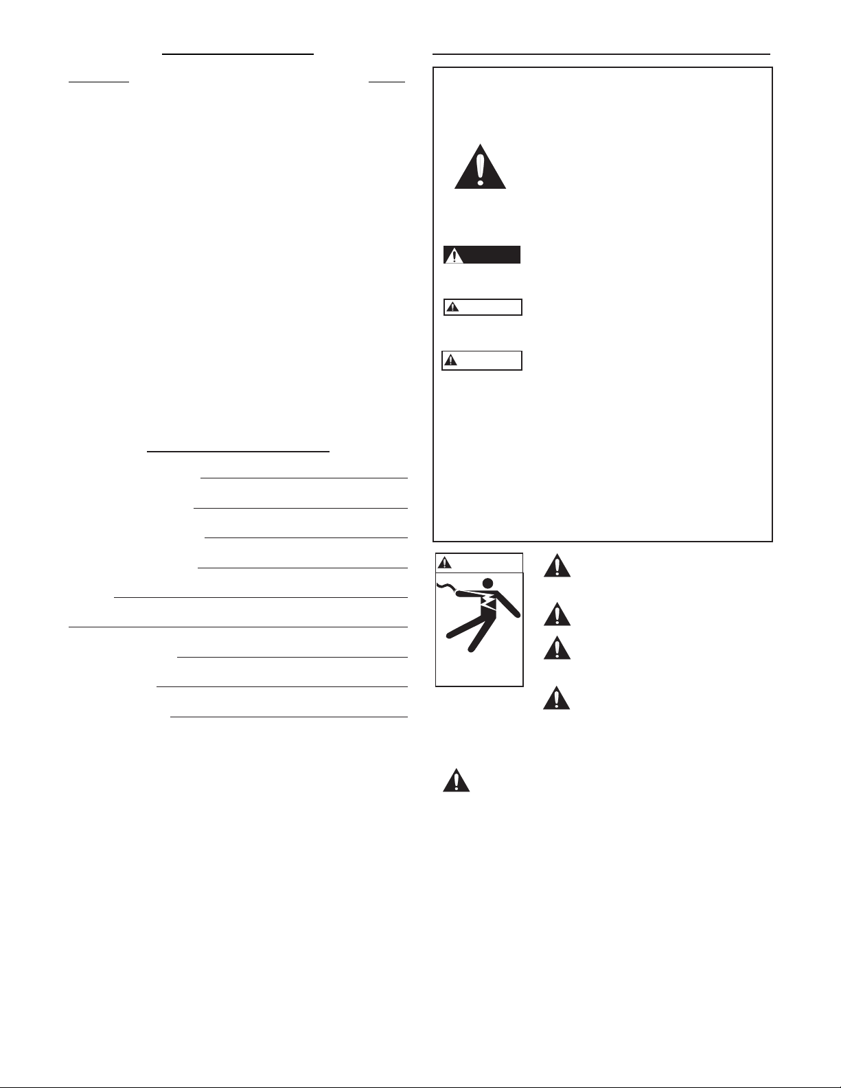
Hazardous voltage
can shock, burn or
cause death.
Table of Contents
Safety Instructions
SUBJECT PAGE
Data Plate Interpretation ....................................................3
Product Description ............................................................3
Dimensions .......................................................................3
Applications ......................................................................3
Technical Data .................................................................. 3
Installation ..........................................................................4
Electrical Connections ........................................................4
Level Switch Operation ...................................................4
Operation .......................................................................... 4
Care and Maintenance ...................................................... 5
Inspection .........................................................................5
Tightening and Lubricating Screws...................................5
Spare Parts ..........................................................................5
Limited Warranty ...............................................................6
Owner’s Information
Pump Model Number:
Pump Serial Number:
Motor Model Number:
TO AVOID SERIOUS OR FATAL PERSONAL INJURY
OR MAJOR PROPERTY DAMAGE, READ AND
FOLLOW ALL SAFETY INSTRUCTIONS IN THE
MANUAL AND ON THE PUMP.
This is a SAFETY ALERT SYMBOL.
When you see this symbol on the pump
or in the manual, look for one of the following signal words and be alert to the
potential for personal injury or property
damage.
Warns of hazards that WILL cause serious
personal injury, death or major property
damage.
Warns of hazards that CAN cause serious
personal injury, death or major property
damage.
Warns of hazards that CAN cause personal
injury or property damage.
NOTICE: INDICATES SPECIAL INSTRUCTIONS
WHICH ARE VERY IMPORTANT AND
MUST BE FOLLOWED.
THIS MANUAL IS INTENDED TO ASSIST IN THE
INSTALLATION AND OPERATION OF THIS UNIT.
THOROUGHLY REVIEW ALL INSTRUCTIONS
AND WARNINGS PRIOR TO PERFORMING ANY
WORK ON THIS PUMP.
MAINTAIN ALL SAFETY DECALS.
Motor Serial Number:
Dealer:
Dealer Telephone:
Purchase Date:
Installation Date:
Install, ground and wire according to local and National Electrical
Code Requirements.
Install an all leg disconnect switch
near the pump.
Disconnect and lockout electrical
power before installing or servicing
the pump.
Electrical supply must match
motor’s nameplate specifications.
Incorrect voltage can cause fire,
damage motor and void the warranty.
Single phase pump motors are equipped with an automatic thermal protector, which opens the motor’s
electrical circuit when an overload condition exists.
This can cause the pump to start unexpectedly.
2
Page 3
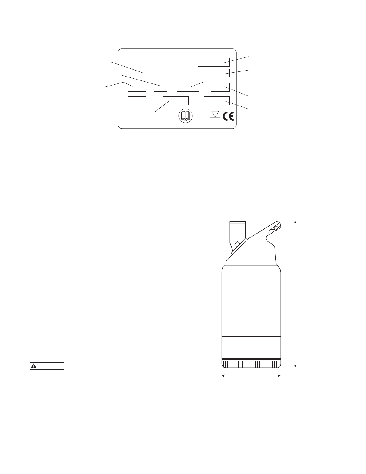
Data Plate Interpretation
WARNING
Model
Frequency
Rated voltage
Rated current
Ouput power
Made in Sweden
Type
U
IPA
IEC 335-2-41 Class F
561 71 00
VH
Hz
P/N
No.
Q
max
IP 68
max
5 m
Part number
Serial number
Weight
max
H
Qmax
Note: The Nameplate HP ratings on these dewatering pumps have been converted from the common European
Kw designation. This created a slight difference between the HP rating used in our literature versus the
pump’s nameplate HP. Therefore, when using this manual:
½ HP Model = a .6 nameplate rating
1 HP Model = 1.1 nameplate rating
Product Description
Dimensions
APPLICATIONS
Dewatering pumps are intended to be used for
pumping water which may contain abrasive particles.
The pumped liquid may contain particles up to a size
which corresponds to the openings in the strainer.
TECHNICAL DATA
Liquid temperature: 41- 95ºF (5-35ºC)
The pH of the pumped liquid: 3–8
Depth of immersion: max. 16.5 ft (5 m).
Discharge connection:
2" (50 mm) hose, 2"-11.5 NPSM or 2" NPT
Oil type:
Mobil Whiterex or Shell Ondina etc. with viscosity
class ISO VG 15 to 32. 0.17 liter.
The pump may not be used in an explosive
or flammable environment or for pumping
flammable liquids.
½ HP = 15.8"
1 HP = 17"
3
Page 4
WARNING
WARNING
Installation
Run the cables so that they do not have any sharp bends
and are not pinched.
Connect the motor cable to a grounded power supply.
See “Electrical connections”.
Connect a discharge hose to the threaded discharge
connection. The pump is now fitted with a discharge hub
which may be adjusted to provide either vertical (std.)
or horizontal discharge. Simply remove the (2) hex head
cap screws holding the discharge hub, turn the discharge
hub 180º and reinstall the (2) screws.
Lower the pump into the sump.
Place the pump on a base which will prevent it from
sinking into a soft sump bottom. Alternati vely, the pump
can be suspended by its handle just above the sump bottom.
NOTICE: WHERE REQUIRED BY LOCAL AUTHOR-
ITIES AN ACCEPTABLE MOTORCIRCUIT SWITCH OR OTHER DISCONNECTING DEVICE SHALL BE PROVIDED
AT THE TIME OF INSTALLATION.
NOTICE: AT CERTAIN INSTALLATIONS AND
OPERATION POINTS ON THE PUMP
CURVE THE NOISE LEVEL, 70 DB, CAN
BE EXCEEDED.
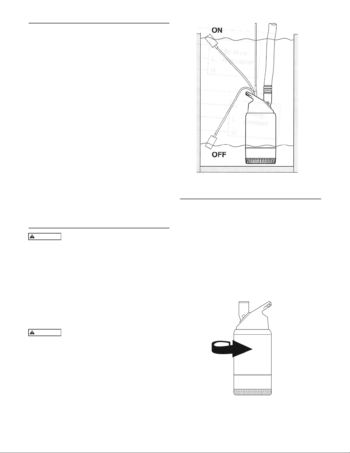
LEVEL SWITCH OPERATION
Pump control by use of level switch.
Operation
BEFORE STARTING
Electrical Connections
All electrical equipment must be grounded.
This applies to both pump equipment and
any monitoring equipment. Failure to heed this
warning may cause a lethal accident. Make sure that the
ground lead is correctly connected by testing it.
All electrical work shall be carried out under the supervision
of an authorized electrician.
Local codes and regulations shall be complied with.
Check that the main voltage and frequency agree with the
specifications on the pump data plate.
Make sure that the pump is correctly grounded.
If people are likely to come into
physical contact with the pump or pumped
media (liquid), e.g on construction sites or farms etc.,
the grounded socket must have an additional groundfault protection device (GFI) connected. When pumping
near a lake (Jetties, beaches, ponds and fountains etc.) a
safety-distance of at least 65 ft. (20 meters) between the
people and the pump is applicable. The pump must never
be placed directly into a swimming pool unless it is shut
down for maintenance. If used in connection with
swimming pools, special safety regulations apply.
Check the oil level in the oil casing.
Remove the fuses or open the circuit breaker and check
that the impeller can be rotated by hand.
Check that the monitoring equipment (if any) works.
Check the direction of rotation. The impeller shall
rotate clockwise, as viewed from above. When started,
the pump will jerk in the opposite direction to the
direction in which the impeller rotates. See the figure.
STARTING JERK
4
Page 5
WARNING
WARNING
CLEANING
WARNING
WARNING
If the pump has been running in very dirty water, let it
run for a while in clean water, or flush it through the
discharge connection. If clay, cement or other similar
dirt is left in the pump it may clog the impeller and seal,
preventing the pump from working.
During a long period out of operation, the pump must
be test run every other month to prevent the mechanical
seals from sticking together.
Watch out for the starting jerk, which can
be powerful.
Always lift the pump by its carrying handle
or lifting eyes, never by the motor cable or
the hose.
Care and Maintenance
Kit type ½ HP 1 HP
60Hz, Kit No. 60Hz, Kit No.
Impeller Kit 15K11 15K12
Diffuser Kit 15K13 15K13
Outer Seal Kit 15K14 15K14
Each Kit contains the following parts:
Impeller Kit Impeller, Impeller screw,
Protective plug, Washer,
Assembly instruction
Diffuser Kit Diffuser, Barrel nuts, Screws,
Washers, Assembly instruction
Outer seal Kit Mechanical face-seal unit,
Assembly instruction
Please contact your local distributor for further details
regarding spare parts etc.
INSPECTION
Regular inspection and preventive maintenance ensure
more reliable operation.
The pump should be inspected at least twice a year, more
frequently under severe operating conditions.
TIGHTENING SCREWS
During assembly or service of the pump we recommend
that the screws be tightened to approximately
4.5 - 6 ft lbs (6-8Nm).
This tightening torque ensures that the parts are correctly
fastened and that the pump will operate as intended.
NOTICE: Make sure that the oil-plug screw is not
tightened too hard.
Be sure to disconnect the power supply
before attempting inpection, as the pump
may start automatically.
LUBRICATING SCREWS
To maintain screw tightness use a little mineral oil on all
non-stainless screws (not synthetic lubricants!).
NOTICE: When using stainless steel screws on stainless
steel parts we recommend that ARAL DEGOL
GS 460 or National Chemseal THREAD-EZE
lubricants be used to prevent screws from
seizing or getting stuck.
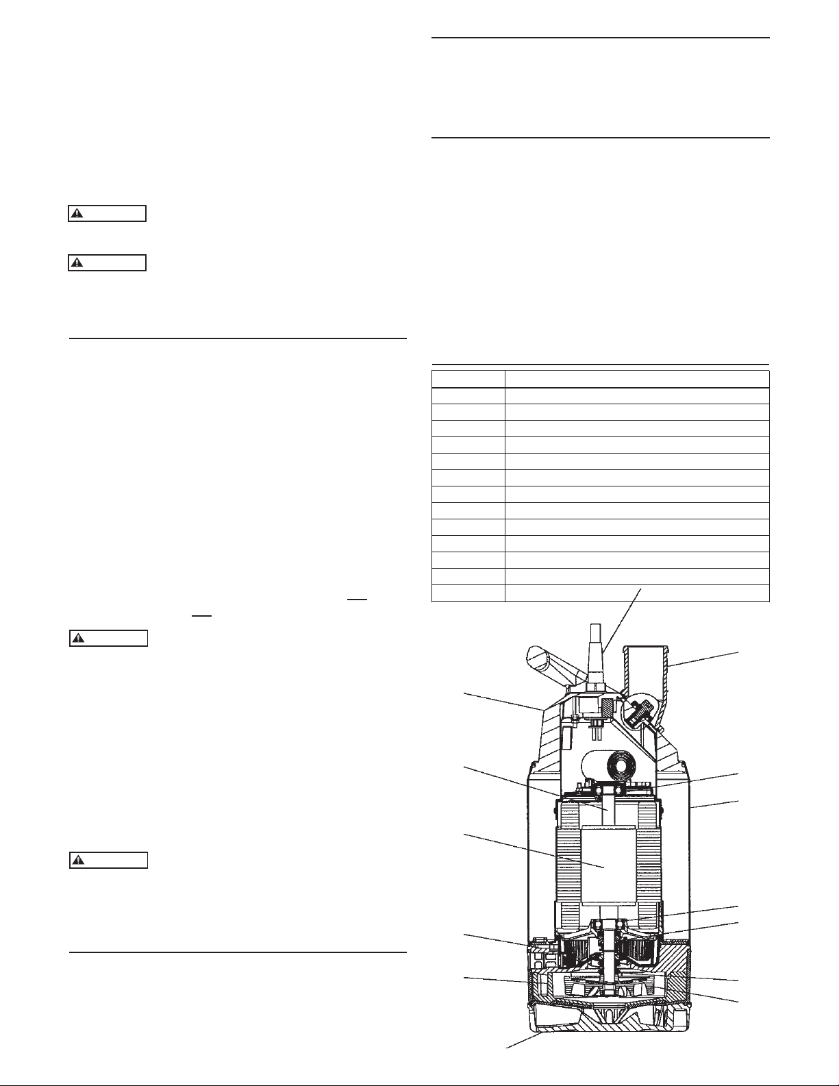
Main Parts
Item No. Description
1 Discharge
2 Power cord
3 Handle/cover
4 Support bearing
5 Pump casing
6 Main bearing
7 Inner mechanical seal
8 Outer mechanical seal
9 Impeller
10 Suction cover
11 Strainer
12 Oil plug
13, 14 Motor
3
14
13
2
1
4
5
If the motor cable on this pump is damaged
the cable may only be changed by a repair
shop authorized by the manufacturer. This is necessary as
special tools are required to change the cable.
Spare Parts
SPARE PART KITS
Spare parts for the dewatering pumps are available in
handy kits to make service and repair work easier. Each
kit contains an instruction sheet together with the
replacement parts.
6
12
10
11
7
8
9
5
Page 6

This warranty applies to all water systems pumps manufactured by Red Jacket Water Products.
Any part or parts found to be defective within the warranty period shall be replaced at no charge to the dealer during the warranty period. The war-
ranty period shall exist for a period of twelve (12) months from date of installation or eighteen (18) months from date of manufacture, whichever
period is shorter.
A dealer who believes that a warranty claim exists must contact the authorized Red Jacket Water Products distributor from whom the pump was
purchased and furnish complete details regarding the claim. The distributor is authorized to adjust any warranty claims utilizing the Red Jacket Water
Products Customer Service Department.
The warranty excludes:
(a) Labor, transportation and related costs incurred by the dealer;
(b) Reinstallation costs of repaired equipment;
(c) Reinstallation costs of replacement equipment;
(d) Consequential damages of any kind; and,
(e) Reimbursement for loss caused by interruption of service.
For purposes of this warranty, the following terms have these definitions:
(1) “Distributor” means any individual, partnership, corporation, association, or other legal relationship that stands between Red Jacket Water Products
and the dealer in purchases, consignments or contracts for sale of the subject pumps.
(2) “Dealer” means any individual, partnership, corporation, association, or other legal relationship which engages in the business of selling or leasing
pumps to customers.
(3) “Customer” means any entity who buys or leases the subject pumps from a dealer. The “customer” may mean an individual, partnership, corpora-
tion, limited liability company, association or other legal entity which may engage in any type of business.
THIS WARRANTY EXTENDS TO THE DEALER ONLY.
RED JACKET WATER PRODUCTS LIMITED WARRANTY
Xylem, Inc.
2881 East Bayard Street Ext., Suite A
Seneca Falls, NY 13148
Phone: (866) 325-4210
Fax: (888) 322-5877
www.xyleminc.com/brands/redjacketwaterproducts
Red Jacket Water Products is a trademark of Xylem Inc. or one of its subsidiaries.
© 2012 Xylem Inc. IM162 Revision Number 3 July 2012
Page 7

MANUAL DE INSTRUCCIÓN
IM162
Bomba de achique
Bomba de achique para empresas constructoras
INSTRUCCIONES PARA LA INSTALACIÓN, OPERACIÓN Y MANTENIMIENTO
Page 8

ADVERTENCIA
CUIDADO
ADVERTENCIA
Un voltaje peligroso puede
producir golpes el ctricos,
quemaduras o la muerte.
Índice
Instrucciones de seguridad
TEMA PÁGINA
Interpretación de los datos de la placa................................9
Descripción del producto ...................................................9
Aplicaciones ........................................................................9
Datos técnicos .....................................................................9
Dimensiones .......................................................................9
Instalación ....................................................................... 10
Conexiones eléctricas ...................................................... 10
Reguladores de nivel ........................................................ 10
Funcionamiento ............................................................... 10
Cuidado y mantenimiento ............................................... 11
Inspección ........................................................................ 11
Ajuste y lubricación de los tornillos ................................. 11
Piezas de repuesto ............................................................ 11
Garantía limitada ............................................................. 13
Información del propietario
Número de modelo de la bomba:
Número de serie de la bomba:
Número de modelo del motor:
Número de serie del motor:
Comerciante:
PARA EVITAR LESIONES GRAVES O FATALES Y
DAÑOS MATERIALES IMPORTANTES, LEA Y SIGA
TODAS LAS INSTRUCCIONES DE SEGURIDAD QUE
SE INCLUYEN ES ESTE MANUAL Y EN LA BOMBA.
Éste es un SÍMBOLO DE ALERTA DE
SEGURIDAD. Cuando vea este símbolo
en la bomba o en el manual, busque una de
las siguientes palabras de señal y esté alerta
ante la posibilidad de lesiones personales o
daños materiales.
PELIGRO
Advierte los peligros que CAUSARÁN
lesiones personales graves, la muerte o
daños materiales importantes.
Advierte los peligros que PUEDEN causar
lesiones personales graves, la muerte o
daños materiales importantes.
Advierte acerca de riesgos que PUEDEN
causar lesiones personales o daños
materiales.
AVISO: INDICA QUE EXISTEN INSTRUCCIONES
ESPECIALES QUE SE DEBEN SEGUIR YA
QUE SON MUY IMPORTANTES.
ESTE MANUAL PRETENDE AYUDAR EN LA INSTALACIÓN Y FUNCIONAMIENTO DE ESTA UNIDAD. EXAMINE MINUCIOSAMENTE TODAS LAS
INSTRUCCIONES Y ADVERTENCIAS ANTES DE
REALIZAR ALGÚN TRABAJO EN ESTA BOMBA.
MANTENGA TODAS LAS CALCOMANÍAS DE
SEGURIDAD.
Teléfono del comerciante:
Fecha de compra:
Fecha de instalación:
Instale, conecte a tierra y cablee de
acuerdo a los requisitos del Código
Nacional Eléctrico.
Instale un interruptor de
desconexión de todos los circuitos
cerca de la bomba.
Desconecte y bloquee la energía
eléctrica antes de instalar o realizar
servicios a la bomba.
El suministro eléctrico debe concordar con las
especificaciones de la placa de identificación del
motor. El voltaje incorrecto puede provocar incendio,
dañar el motor y anular la garantía.
Los motores monofásicos de la bomba se encuentran
equipados con un protector térmico automático, el
cual abre el circuito eléctrico del motor cuando existe
una sobrecarga. Este puede provocar que la bomba
arranque de manera inesperada.
8
Page 9

Interpretación de la placa de datos
ADVERTENCIA
Modelo
Frecuencia
Voltaje nominal
Corriente nominal
Potencia de salida
Made in Sweden
Type
U
IPA
IEC 335-2-41 Class F
561 71 00
VH
Hz
P/N
No.
Q
max
IP 68
max
5 m
Número de pieza
Número de serie
Peso
max
H
Qmax
Nota: Los índices de HP de la placa de identificación en estas bombas de achique han sido convertidos de
la designación europea común de Kw. Esto crea una pequeña diferencia entre el índice de HP utilizado en
nuestro material de literatura en oposición al HP que figura en la placa de identificación de la bomba. Además,
cuando utilice este manual tenga presente:
Modelo de ½ HP = un índice de 0,6 en la placa de identificación
Modelo de 1 HP = un índice de 1,1 en la placa de identificación
DimensionesDescripción del producto
APLICACIONES
Las bombas de achique están diseñadas para bombear
agua que pueda contener partículas abrasivas.
El líquido bombeado puede contener partículas hasta del
tamaño correspondiente a las aberturas en los filtros.
DATOS TÉCNICOS
Temperatura del líquido: 41 – 95 ºF (5-35 ºC)
pH del líquido bombeado: 3-8
Profundidad de inmersión: 16,5 pies (5 m) máx.
Conexión de descarga:
manguera de 2" (50 mm), 2"-11,5 NPSM o 2" NPT
Tipo de aceite:
Mobil Whiterex o Shell Ondina, etc. con clase de
viscosidad ISO VG 15 a 32. 0,17 litros.
La bomba no debe utilizarse en entornos
inflamables o donde puedan producirse
explosiones ni para bombear líquidos inflamables.
½ HP = 15.8"
1 HP = 17"
7.25"
9
Page 10

Instalación
ADVERTENCIA
ADVERTENCIA
Coloque los cables de manera que no presenten
acodamientos filosos o que queden apretados.
Conecte el cable del motor a un suministro eléctrico con
conexión a tierra. Vea “Conexiones eléctricas”.
Conecte una manguera de descarga a la conexión de
descarga roscada.
Descienda la bomba al sumidero.
Coloque la bomba sobre una base que evitará que
la bomba se hunda en el fondo blando del sumidero.
Alternativamente, la bomba puede estar suspendida
de la manija apenas por encima del fondo del sumidero.
AVISO: DONDE LAS AUTORIDADES LOCALES
ASÍ LO EXIJAN, DEBERÁ SUMINISTRAR
SE UN CONMUTADOR DE CIRCUITO
DE MOTOR U OTRO DISPOSITIVO DE
DESCONEXIÓN AL MOMENTO
DE LA INSTALACIÓN.
AVISO: EN CIERTAS INSTALACIONES Y PUNTOS
DE FUNCIONAMIENTO, LA CURVA DE
NIVEL DE RUIDO DE LA BOMBA PUEDE
EXCEDER LOS 70 DB.
REGULADORES DE NIVEL
Control de la bomba mediante el uso de interruptor de nivel.
Funcionamiento
Conexiones eléctricas
Todos los equipos eléctricos deben estar
conectados a tierra. Esto se aplica tanto al
equipo de la bomba como a los equipos de control. La
omisión de esta advertencia puede causar en accidente
mortal. Asegúrese de que el cable a tierra se encuentre
conectado correctamente realizando una prueba.
Todos los trabajos eléctricos deben realizarse bajo la
supervisión de un electricista autorizado.
Deben cumplirse los códigos y ordenanzas locales.
Controle que el voltaje principal y la frecuencia cumplan
con las especificaciones que figuran en la placa de datos
de la bomba.
Asegúrese de que la bomba se encuentre conectada a
tierra de manera correcta.
Si las personas estarán en contacto físico
con la bomba o con el medio bombeado
(líquido), es decir, en sitios de construcción o granjas, etc.,
el tomacorriente de la conexión a tierra debe tener conectado un dispositivo de protección de fuga a tierra adicional
(GFI). Cuando se bombee cerca de un lago (espigones,
playas, estanques o manantiales, etc.) corresponde que haya
una distancia de seguridad de 65 pies (20 metros) entre
las personas y la bomba. Nunca debe colocarse la bomba
directamente dentro de una piscina a menos que se encuentre cerrada por tareas de mantenimiento. Si se utiliza la
bomba en conexiones con piscinas, se aplican ordenanzas
de seguridad especiales.
ANTES DEL ARRANQUE
Controle el nivel de aceite en el depósito de aceite.
Extraiga los fusibles o abra el disyuntor y controle que
pueda rotar el impulsor con la mano.
Controle que el equipo de control (si existiera) funcione.
Controle la dirección de rotación. El impulsor debe rotar
en sentido horario, visto desde arriba. Cuando arranca, la
bomba experimenta un tirón en la dirección opuesta a la
dirección que rota el impulsor. Vea la figura.
TIRÓN DE ARRANQUE
10
Page 11

ADVERTENCIA
ADVERTENCIA
LIMPIEZA
ADVERTENCIA
ADVERTENCIA
Si la bomba ha estado funcionando en aguas muy sucias,
permita que funcione por un momento con agua limpia o
púrguela a través de la conexión de descarga. Si hubiera
quedado arcilla, cemento u otra suciedad similar en la
bomba es posible que se atasque el impulsor y el sello,
impidiendo que la bomba funcione.
Durante un largo período de inactividad, se debe probar la bomba cada dos meses para evitar que los sellos
mecánicos se peguen entre sí.
Ponga atención en las sacudidas de
arranque ya que pueden ser fuertes.
Siempre levante la bomba por el asa de
transporte o argollas de izada, nunca por
el cable del motor o la manguera.
Cuidado y Mantenimiento
INSPECCIÓN
Inspeccionar y realizar tareas de mantenimiento
regularmente aseguran un funcionamiento más confiable.
Se deberá inspeccionar la bomba al menos dos veces al año
y con más frecuencia si las condiciones de funcionamiento
son muy estrictas.
AJUSTE DE LOS TORNILLOS
Recomendamos ajustar los tornillos a aproximadamente
4,5 – 6 pies/lb (6-8 Nm) durante el montaje o servicio
de la bomba.
Piezas de repuesto
KITS DE REPUESTO
Las piezas de repuesto para las bombas de achique se
encuentran disponibles en kits para facilitar el servicio y la
reparación. Cada equipo contiene una hoja de instrucciones
junto con las piezas de recambio.
Tipo de kit ½ HP, 60 Hz 1 HP, 60 Hz
Equipo Nº Equipo Nº
Kit del impulsor 15K11 15K12
Kit del difusor 15K13 15K13
Kit del sello externo 15K14 15K14
Cada kit contiene las siguientes piezas:
Kit del impu lsor Impulsor, tornillo del impulsor,
tapón de protección, arandela,
instrucciones de montaje
Kit del difusor Difusor, tuercas cilíndricas,
tornillos, arandelas,
instrucciones de montaje
Kit del sello externo Unidad mecánica del sello
externo, instrucciones de
montaje
Comuníquese con su distribuidor local para conocer más
detalles con respecto a las piezas de repuesto, etc.
Esta torsión de ajuste asegura que las piezas estén
correctamente sujetas y que la bomba funcione
de la manera deseada.
AVISO: Asegúrese de que el tapón roscado del depósito de
aceite no se encuentre excesivamente ajustado.
Asegúrese de desconectar el suministro eléctrico antes de realizar la inspección ya que la
bomba puede arrancar automáticamente.
LUBRICACIÓN DE LOS TORNILLOS
Para conservar la hermeticidad de los tornillos, utilice un
poco de aceite mineral en todos los tornillos no-oxidables
(no utilizar lubricantes sintéticos).
AVISO: Cuando utilice tornillos de acero inoxidable
en piezas de acero inoxidable, recomendamos el uso de
lubricantes ARAL DEGOL GS 460 o National Chemseal
THREAD-EZE para evitar que los tornillos se agarroten o
se atasquen.
Si el cable del motor de esta bomba se daña,
solamente podrá repararlo un comercio de
reparaciones autorizado por el fabricante. Esto es necesario
ya que se requieren herramientas especiales para cambiar
el cable
11
Page 12

PIEZAS PRINCIPALES
Artículo Denominación
1 Conexión de descarga
2 Entrada del cable
3 Asa / cubierta
4 Cojinete de soporte
5 Carcasa de la bomba
6 Cojinete principal
7 Sello mecánico interno
8 Sello mecánico externo
9 Impulsor
10 Difusor
11 Filtro
12 Tapón del depósito de aceite
13 Motor
2
1
3
14
13
12
10
11
4
5
6
7
8
9
12
Page 13

GARANTÍA LIMITADA DE RED JACKET WATER PRODUCTS
Esta garantía es aplicable a todas las bombas para sistemas de agua fabricadas por Red Jacket Water Products.
Toda parte o partes que resultaren defectuosas dentro del período de garantía serán reemplazadas durante dicho período de garantía sin cargo para el
comerciante. Tal período de garantía se extiende por doce (12) meses a partir de la fecha de instalación, o dieciocho (18) meses a partir de la fecha de
fabricación, la que se cumpla primero.
El comerciante que considere que existe lugar a un reclamo de garantía deberá ponerse en contacto con el distribuidor autorizado de Red Jacket Water
Products del cual adquiriera la bomba y brindar información detallada con respecto al reclamo. El distribuidor está autorizado a liquidar todos los
reclamos por garantía a través del Departamento de Servicios a Clientes de Red Jacket Water Products.
La presente garantía excluye:
(a) La mano de obra, el transporte y los costos relacionados en los que incurra el comerciante;
(b) los costos de reinstalación del equipo reparado;
(c) los costos de reinstalación del equipo reemplazado;
(d) daños emergentes de cualquier naturaleza; y
(e) el reembolso de cualquier pérdida causada por la interrupción del servicio.
A los fines de esta garantía, los términos “Distribuidor”, “Comerciante” y “Cliente” se definen como sigue:
(1) “Distribuidor” es aquel individuo, sociedad, corporación, asociación u otra entidad jurídica que opera entre Red Jacket Water Products y el comer-
ciante para la compra, consignación o contratos de venta de las bombas en cuestión.
(2) “Comerciante” es todo individuo, sociedad, corporación asociación u otra entidad jurídica que realiza negocios de venta o alquiler-venta (leasing)
de bombas a los clientes.
(3) “Cliente” es toda entidad que compra o adquiere bajo la modalidad de leasing las bombas en cuestión de un comerciante. El término “cliente”
puede significar un individuo, sociedad, corporación, sociedad de responsabilidad limitada, asociación o cualquier otra entidad jurídica con actividades en cualquier tipo de negocios.
LA PRESENTE GARANTÍA SE EXTIENDE AL COMERCIANTE ÚNICAMENTE.
Xylem, Inc.
2881 East Bayard Street Ext., Suite A
Seneca Falls, NY 13148
Teléfono: (866) 325-4210
Fax: (888) 322-5877
www.xyleminc.com/brands/redjacketwaterproducts
Red Jacket Water Products son una marca registrada de Xylem Inc. o una de sus filiales.
© 2012 Xylem Inc. IM162 Revisión Número 3 Julio 2012
13
Page 14

MANUEL D'UTILISATION
IM162
Pompes d'assèchement
Pompe de chantier
DIRECTIVES D’INSTALLATION, D’UTILISATION ET D’ENTRETIEN
14
Page 15

DANGER
AVERTISSEMENT
ATTENTION
AVERTISSEMENT
Les tensions dangereuses
peuvent causer un choc
électrique, des brûlures et
la mort.
Table des matières
Consignes de sécurité
SUJET PAGE
Consignes de sécurité ........................................................15
Informations sur la plaque signalétique .............................16
Description du produit ......................................................16
Applications ...................................................................16
Données techniques générales .......................................16
Dimensions ....................................................................19
Installation .........................................................................17
Raccordement électrique ...................................................17
Régulateur de niveau .....................................................17
Utilisation ..........................................................................17
Entretien ............................................................................18
Inspection ......................................................................18
Serrage des vis ................................................................18
Lubrification des vis .......................................................18
Pièces de rechange .............................................................18
Garantie limitée .................................................................20
Informations pour le propriétaire
No de modèle de la pompe :
No de série de la pompe :
No de modèle du moteur :
No de série du moteur :
Détaillant :
No de téléphone du détaillant :
Date d’achat :
Date d’installation :
AFIN DE PRÉVENIR LES BLESSURES GRAVES OU
MORTELLES ET LES DOMMAGES MATÉRIELS
IMPORTANTS, LIRE ET SUIVRE TOUTES LES
CONSIGNES DE SÉCURITÉ FIGURANT DANS
LE MANUEL ET SUR LA POMPE.
Le symbole ci-contre est un SYMBOLE
DE SÉCURITÉ employé pour signaler
les mots-indicateurs dont on trouvera la
description ci-dessous. Sa présence sert à
attirer l’attention afin d’éviter les blessures
et les dommages matériels.
Prévient des risques qui VONT causer des
blessures graves, la mort ou des dommages
matériels importants.
Prévient des risques qui PEUVENT causer
des blessures graves, la mort ou des dommages matériels importants.
Prévient des risques qui PEUVENT causer
des blessures ou des dommages matériels.
AVIS : SERT À ÉNONCER LES DIRECTIVES
SPÉCIALES DE GRANDE IMPORTANCE
QUE L’ON DOIT SUIVRE.
LE PRÉSENT MANUEL A POUR BUT DE FACILITER L’INSTALLATION ET L’UTILISATION DE LA
POMPE. LIRE SOIGNEUSEMENT CHAQUE DIRECTIVE ET AVERTISSEMENT AVANT D’EFFECTUER
TOUT TRAVAIL SUR LA POMPE.
N’ENLEVER AUCUN AUTOCOLLANT DE
SÉCURITÉ.
Installer la pompe, la mettre à la
terre et la brancher suivant les
prescriptions du code provincial ou
national de l’électricité pertinent et
les règlements locaux.
Poser un sectionneur tout conducteur près de la pompe.
Verrouiller la source de courant en
position hors circuit avant de procéder à l’installation ou à l’entretien
de la pompe.
L’alimentation électrique DOIT être conforme aux
spécifications de la plaque signalétique de la pompe.
Une tension inappropriée peut causer un incendie ou
des dommages au moteur et annule la garantie.
Le protecteur thermique des moteurs de pompe monophasés coupe le courant lorsqu’il y a surcharge et le
rétablit automatiquement, redémarrant ainsi la pompe
inopinément.
15
Page 16

Informations sur la plaque signalétique
AVERTISSEMENT
Modèle
Fréquence
Made in Sweden
Type
P/N
No.
Numéro de pièce
Numéro de série
Poids
Tension nominale
Courant nominal
Puissance de sortie
U
IPA
IEC 335-2-41 Class F
561 71 00
VH
Hz
Q
max
IP 68
max
Hauteur de charge
maximale
Débit maximal
5 m
Nota : La puissance nominale en hp affichée sur la plaque signalétique des pompes de chantier (d’assèchement) en question a
été convertie à partir de la puissance en kW communément employée en Europe, d’où l’existence d’une légère
différence entre la puissance en hp figurant dans la documentation Red Jacket Water Products et celle de la plaque.
On utilisera donc le présent manuel en tenant compte des puissances comme qui suit :
½ hp = 0,6 x la puissance nominale figurant sur la plaque ;
1 hp = 1,1 x la puissance nominale inscrite sur la plaque.
Description du produit
Dimensions
APPLICATIONS
Les pompes de chantier (d’assèchement) sont conçues pour
pomper de l’eau pouvant contenir des particules abrasives,
mais dont la grosseur ne doit pas dépasser celle des trous de
la crépine des pompes.
DONNÉES TECHNIQUES GÉNÉRALES
Température du liquide pompé : 5 à 35 ºC (41 à 95 ºF)
pH du liquide pompé : 3 à 8
Profondeur d’immersion max. : 5 m (16,5 pi)
Raccords de refoulement :
50 mm (2 po) pour tuyau souple ; 2 po — 11.5, NPSM ;
ou 2 po, NPT
Quantité et type d’huile :
0,17 litre d’huile Mobil Whiterex, Shell Ondina, etc., de
viscosités ISO VG 15 à 32
La pompe ne peut être utilisée en milieu
inflammable ou déflagrant ni pour
les liquides inflammables.
½ HP = 15.8"
1 HP = 17"
7.25"
16
Page 17

Installation
AVERTISSEMENT
AVERTISSEMENT
RÉGULATEUR DE NIVEAU
Passer les câbles de façon à ce qu’ils ne soient ni pliés ni
pincés.
Connecter le câble de moteur à une source d’alimentation
mise à la terre (v. « Raccordement électrique »).
Fixer un tuyau souple au raccord de refoulement fileté
de la pompe.
Descendre la pompe dans le puisard.
Si le fond du puisard est vaseux, placer la pompe sur une base
pour ne pas qu’elle s’enfonce, ou bien la suspendre par sa
poignée juste au-dessus du fond du puisard.
AVIS : LES RÈGLEMENTS LOCAUX PEUVENT
EXIGER QUE L’ON POSE UN INTERRUPTEUR
OU UN AUTRE APPAREIL DE
SECTIONNEMENT ACCEPTABLES SUR LE
CIRCUIT D’ALIMENTATION DU MOTEUR
DE LA POMPE AU COURS DE
L’INSTALLATION DE CETTE DERNIÈRE.
AVIS : DANS CERTAINES INSTALLATIONS ET À
CERTAINS POINTS DE LA COURBE DE
PERFORMANCES DE LA POMPE, LE BRUIT
DE FONCTIONNEMENT PEUT DÉPASSER
70 dB.
Raccordement électrique
DÉMARRAGE
ARRÊT
La pompe est commandée par un contacteur de niveau.
Utilisation
Tout le matériel électrique doit être mis à la
terre, qu’il s’agisse de la pompe ou du matériel de contrôle. L’inobservation du présent avertissement
peut entraîner un accident mortel. Faire un essai de conductivité sur le fil de terre pour s’assurer qu’il est bien connecté.
L’installation de tout le matériel électrique doit être supervisée par un électricien.
On doit se conformer au code provincial ou national de
l’électricité pertinent et aux règlements locaux.
S’assurer que la tension et la fréquence du courant d’alimentation secteur conviennent à celles qui sont stipulées sur la
plaque signalétique de la pompe.
Voir à ce que la pompe soit mise à la terre correctement.
S’il y a risque de contact avec la pompe ou
le liquide pompé, comme cela peut être le
cas sur le chantier, la ferme, etc., on doit installer sur la prise
de courant, mise à la terre, une protection contre les défauts
à la terre. Quand la pompe est située près d’un lac, d’un
embarcadère, d’une plage, d’un bassin, d’une fon-taine, etc.,
il faut maintenir une distance de sécurité minimale de 20 m
(65 pi) entre la pompe et les gens. On ne doit jamais placer
la pompe dans une piscine, sauf si la piscine est hors d’usage
pour entretien. Des règlements de sécurité spéciaux s’appliquent quant à l’emploi de la pompe pour les piscines.
PRÉPARATIFS DE MISE EN SERVICE
Vérifier le niveau du réservoir d’huile.
À l’aide du disjoncteur ou des fusibles, mettre la pompe hors
circuit, puis vérifier si la roue de la pompe peut tourner à la
main.
S’assurer que le matériel de contrôle fonctionne s’il est
installé.
Vérifier le sens de rotation de la pompe. Vue du haut de la
pompe, la roue doit tourner en sens horaire. En pareil cas,
la pompe donnera une secousse en sens contraire (antihoraire) en démarrant (voir la figure ci-dessous).
SECOUSSE DE DÉMARRAGE
17
Page 18

NETTOYAGE
AVERTISSEMENT
AVERTISSEMENT
AVERTISSEMENT
AVERTISSEMENT
Si la pompe a servi à pomper de l’eau très sale, la faire
fonctionner pendant un certain temps dans de l’eau propre
ou la rincer par l’orifice de refoulement. L’argile, le ciment
et toute autre saleté laissés dans la pompe formeront un
dépôt, qui bloquera éventuellement la roue et les garnitures
mécaniques et empêchera la pompe de fonctionner.
Dans le cas des mises hors service de longue durée, on doit
procéder à un essai de fonctionnement de la pompe à tous
les deux mois pour prévenir le grippage des garnitures
mécaniques.
Prendre garde à la secousse de démarrage,
car elle peut être puissante.
Pièces de rechange
ENSEMBLES DE PIÈCES DE RECHANGE
Les pièces de rechange des pompes de chantier sont offertes
dans des ensembles pratiques pour faciliter les travaux d’entretien et de réparation. Chaque ensemble est accompagné
de directives d’assemblage.
Ensemble ½ hp, 60 Hz 1 hp, 60 Hz
No d’ensemble No d’ensemble
Roue 15K11 15K12
Diffuseur 15K13 15K13
Garniture méc. ext. 15K14 15K14
On doit toujours lever la pompe par la poignée ou les œilletons de levage, mais jamais
par le câble de moteur ou le tuyau souple.
Entretien
INSPECTION
L’inspection régulière et l’entretien préventif se traduisent
par une meilleure fiabilité de fonctionnement.
L’inspection de la pompe devrait se faire deux fois par
année, voire plus souvent si les conditions de service sont
difficiles.
SERRAGE DES VIS
Au cours de l’assemblage ou de l’entretien de la pompe,
il est recommandé de serrer les vis entre 6 et 8 N∙m
(4,5 et 6 lbf∙pi).
Le couple de serrage recommandé permet de fixer les pièces
correctement et de faire fonctionner la pompe tel que
prévu.
AVIS : S’assurer que le bouchon du réservoir d’huile n’est
pas vissé trop fort.
Les ensembles contiennent les pièces suivantes :
Roue Roue, vis de roue, bouchon
protecteur, rondelle, directives
d’assemblage
Diffuseur Diffuseur, écrous à portée
cylindrique, vis, rondelles, directives
d’assemblage
Garniture méc. ext. Éléments de garniture mécanique,
directives d’assemblage
S’adresser au distributeur pour avoir plus de détails, y
compris sur les pièces de rechange.
Veiller à couper le courant avant
d’inspecter la pompe, sinon elle pourrait
démarrer inopinément.
LUBRIFICATION DES VIS
Pour maintenir les vis non en inox bien serrées, les
enduire d’un peu d’huile minérale, mais pas de lubrifiant
synthétique !
AVIS : Quand on utilise des vis en inox pour des pièces
en inox, il est suggéré d’employer des
lubrifiants tels que le GS 460 (ARAL DEGOL)
ou le THREAD-EZE (National Chemseal) pour
prévenir le grippage des vis.
Si le câble du moteur de pompe est endom-
magé, il ne pourra être changé que dans un
atelier de réparation agréé par le fabricant, car cela requiert
des outils spéciaux.
18
Page 19

PRINCIPAUX COMPOSANTS
Article Nom
1 Raccord de refoulement
2 Câble de moteur
3 Couvercle à poignée
4 Palier d’appui
5 Corps de pompe
6 Palier principal
7 Garniture mécanique interne
8 Garniture mécanique externe
9 Roue
10 Diffuseur
11 Crépine
12 Bouchon du réservoir d’huile
13 Moteur
2
1
3
14
13
12
10
11
4
5
6
7
8
9
19
Page 20

GARANTIE LIMITÉE DE RED JACKET WATER PRODUCTS
La présente garantie s’applique à chaque pompe de système d’alimentation en eau fabriquée par Red Jacket Water Products.
Toute pièce se révélant défectueuse sera remplacée sans frais pour le détaillant durant la période de garantie suivante expirant la première : douze (12)
mois à compter de la date d’installation ou dix-huit (18) mois à partir de la date de fabrication.
Le détaillant qui, aux termes de cette garantie, désire effectuer une demande de règlement doit s’adresser au distributeur Red Jacket Water Products agréé
chez lequel la pompe a été achetée et fournir tous les détails à l’appui de sa demande. Le distributeur est autorisé à régler toute demande par le biais du
service à la clientèle de Red Jacket Water Products.
La garantie ne couvre pas :
a) les frais de main-d’œuvre ni de transport ni les frais connexes encourus par le détaillant ;
b) les frais de réinstallation de l’équipement réparé ;
c) les frais de réinstallation de l’équipement de remplacement ;
d) les dommages indirects de quelque nature que ce soit ;
e) ni les pertes découlant de la panne.
Aux fins de la présente garantie, les termes ci-dessous sont définis comme suit :
1) « Distributeur » signifie une personne, une société de personnes, une société de capitaux, une association ou autre entité juridique servant
d’intermédiaire entre Red Jacket Water Products et le détaillant pour les achats, les consignations ou les contrats de vente des pompes en question.
2) « Détaillant » veut dire une personne, une société de personnes, une société de capitaux, une association ou autre entité juridique dont les activités
commerciales sont la vente ou la location de pompes à des clients.
3) « Client » signifie une entité qui achète ou loue les pompes en question chez un détaillant. Le « client » peut être une personne, une société de personnes, une société de capitaux, une société à responsabilité limitée, une association ou autre entité juridique se livrant à quelque activité que ce soit.
CETTE GARANTIE SE RAPPORTE AU DÉTAILLANT SEULEMENT.
Xylem, Inc.
2881 East Bayard Street Ext., Suite A
Seneca Falls, NY 13148
Téléphone: (866) 325-4210
Télécopie: (888) 322-5877
www.xyleminc.com/brands/redjacketwaterproducts
Red Jacket Water Products est une marque déposée de Xylem Inc. ou d'une de ses filiales.
© 2012, Xylem Inc. IM162 Révision numéro 3 Juillet 2012
 Loading...