


Volkswagen Golf 2004 User Manual

P
r
o
t
e
c
t
e
d
b
y
c
o
p
y
r
i
g
h
t
.
C
o
p
y
i
n
g
f
o
r
p
r
i
v
a
t
e
o
r
c
o
m
m
e
r
c
i
a
l
p
u
r
p
o
s
e
s
,
i
n
p
a
r
t
o
r
i
n
w
h
o
l
e
,
i
s
n
o
t
p
e
r
m
i
t
t
e
d
u
n
l
e
s
s
a
u
t
h
o
r
i
s
e
d
b
y
V
o
l
k
s
w
a
g
e
n
A
G
.
V
o
l
k
s
w
a
g
e
n
A
G
d
o
e
s
n
o
t
g
u
a
r
a
n
t
e
e
o
r
a
c
c
e
p
t
a
n
y
l
i
a
b
i
l
i
t
y
w
i
t
h
r
e
s
p
e
c
t
t
o
t
h
e
c
o
r
r
e
c
t
n
e
s
s
o
f
i
n
f
o
r
m
a
t
i
o
n
i
n
t
h
i
s
d
o
c
u
m
e
n
t
.
C
o
p
y
r
i
g
h
t
b
y
V
o
l
k
s
w
a
g
e
n
A
G
.
Service
Workshop Manual
Golf 2004 ➤
Golf 2009 ➤
Auxiliary heater
Edition 09.2008
Service Department. Technical Information

P
r
o
t
e
c
t
e
d
b
y
c
o
p
y
r
i
g
h
t
.
C
o
p
y
i
n
g
f
o
r
p
r
i
v
a
t
e
o
r
c
o
m
m
e
r
c
i
a
l
p
u
r
p
o
s
e
s
,
i
n
p
a
r
t
o
r
i
n
w
h
o
l
e
,
i
s
n
o
t
p
e
r
m
i
t
t
e
d
u
n
l
e
s
s
a
u
t
h
o
r
i
s
e
d
b
y
V
o
l
k
s
w
a
g
e
n
A
G
.
V
o
l
k
s
w
a
g
e
n
A
G
d
o
e
s
n
o
t
g
u
a
r
a
n
t
e
e
o
r
a
c
c
e
p
t
a
n
y
l
i
a
b
i
l
i
t
y
w
i
t
h
r
e
s
p
e
c
t
t
o
t
h
e
c
o
r
r
e
c
t
n
e
s
s
o
f
i
n
f
o
r
m
a
t
i
o
n
i
n
t
h
i
s
d
o
c
u
m
e
n
t
.
C
o
p
y
r
i
g
h
t
b
y
V
o
l
k
s
w
a
g
e
n
A
G
.
Service
List of Workshop Manual Repair GroupsList of Workshop Manual
Repair GroupsList of Workshop Manual Repair Groups
Re pa ir G ro up
82 - Auxiliary heating
Technical information should always be available to the foremen and mechanics, because their
careful and constant adherence to the instructions is essential to ensure vehicle road-worthiness and
safety. In addition, the normal basic safety precautions for working on motor vehicles must, as a
matter of course, be observed.
All rights reserved.
No reproduction without prior agreement from publisher.
Copyright © 2010 Volkswagen AG, Wolfsburg K0058991320

P
r
o
t
e
c
t
e
d
b
y
c
o
p
y
r
i
g
h
t
.
C
o
p
y
i
n
g
f
o
r
p
r
i
v
a
t
e
o
r
c
o
m
m
e
r
c
i
a
l
p
u
r
p
o
s
e
s
,
i
n
p
a
r
t
o
r
i
n
w
h
o
l
e
,
i
s
n
o
t
p
e
r
m
i
t
t
e
d
u
n
l
e
s
s
a
u
t
h
o
r
i
s
e
d
b
y
V
o
l
k
s
w
a
g
e
n
A
G
.
V
o
l
k
s
w
a
g
e
n
A
G
d
o
e
s
n
o
t
g
u
a
r
a
n
t
e
e
o
r
a
c
c
e
p
t
a
n
y
l
i
a
b
i
l
i
t
y
w
i
t
h
r
e
s
p
e
c
t
t
o
t
h
e
c
o
r
r
e
c
t
n
e
s
s
o
f
i
n
f
o
r
m
a
t
i
o
n
i
n
t
h
i
s
d
o
c
u
m
e
n
t
.
C
o
p
y
r
i
g
h
t
b
y
V
o
l
k
s
w
a
g
e
n
A
G
.
Contents
Golf 2004 ➤ , Golf 2009 ➤
Auxiliary heater - Edition 09.2008
82 - Auxiliary heating . . . . . . . . . . . . . . . . . . . . . . . . . . . . . . . . . . . . . . . . . . . . . . . . . . 1
1 Auxiliary heater Thermo Top V . . . . . . . . . . . . . . . . . . . . . . . . . . . . . . . . . . . . . . . . . . . . . . 1
1.1 Safety measures for working on vehicles with auxiliary heaters . . . . . . . . . . . . . . . . . . . . 1
2 Notes on general repairs on vehicles with auxiliary heaters . . . . . . . . . . . . . . . . . . . . . . . . 2
2.1 Starting conditions for auxiliary heating (preheater) . . . . . . . . . . . . . . . . . . . . . . . . . . . . . . 2
2.2 Starting conditions for auxiliary heating . . . . . . . . . . . . . . . . . . . . . . . . . . . . . . . . . . . . . . . . 2
3 Rules for cleanliness when working on the auxiliary heater and the fuel system . . . . . . . . 3
4 Repairing auxiliary heater Thermo Top V . . . . . . . . . . . . . . . . . . . . . . . . . . . . . . . . . . . . . . 4
4.1 Removing and installing remote control receiver for auxiliary coolant heater R149 . . . . . . 8
5 Removing and installing auxiliary heater Thermo Top V . . . . . . . . . . . . . . . . . . . . . . . . . . 10
5.1 Components of auxiliary heater Thermo Top V . . . . . . . . . . . . . . . . . . . . . . . . . . . . . . . . . . 11
5.2 Removing auxiliary heater Thermo Top V . . . . . . . . . . . . . . . . . . . . . . . . . . . . . . . . . . . . . . 11
5.3 Installing auxiliary heater Thermo Top V . . . . . . . . . . . . . . . . . . . . . . . . . . . . . . . . . . . . . . 14
5.4 Removing ancillaries of auxiliary heater Thermo Top V . . . . . . . . . . . . . . . . . . . . . . . . . . . . 14
5.5 Dismantling and assembling auxiliary heater Thermo Top V . . . . . . . . . . . . . . . . . . . . . . . . 17
5.6 Inner components of auxiliary heater . . . . . . . . . . . . . . . . . . . . . . . . . . . . . . . . . . . . . . . . . . 19
5.7 Bleeding coolant circuit . . . . . . . . . . . . . . . . . . . . . . . . . . . . . . . . . . . . . . . . . . . . . . . . . . . . 22
6 Connecting auxiliary heater Thermo Top V to coolant circuit . . . . . . . . . . . . . . . . . . . . . . . . 24
6.1 Connection diagram for coolant hoses in vehicles with auxiliary heater, engine codes BKC,
BJB, BLS, BRV . . . . . . . . . . . . . . . . . . . . . . . . . . . . . . . . . . . . . . . . . . . . . . . . . . . . . . . . . . 24
6.2 Connection diagram for coolant hoses in vehicles with auxiliary heating, engine code BMM
. . . . . . . . . . . . . . . . . . . . . . . . . . . . . . . . . . . . . . . . . . . . . . . . . . . . . . . . . . . . . . . . . . . . . . . . 25
6.3 Connection diagram for coolant hoses in vehicles with auxiliary heating, engine codes BLG,
BMY . . . . . . . . . . . . . . . . . . . . . . . . . . . . . . . . . . . . . . . . . . . . . . . . . . . . . . . . . . . . . . . . . . 26
6.4 Connection diagram for coolant hoses in vehicles with auxiliary heating, engine codes AXX,
BPY, BWA . . . . . . . . . . . . . . . . . . . . . . . . . . . . . . . . . . . . . . . . . . . . . . . . . . . . . . . . . . . . . . 27
6.5 Connection diagram for coolant hoses in vehicles with auxiliary heating, engine codes AZV,
BKD, BMN . . . . . . . . . . . . . . . . . . . . . . . . . . . . . . . . . . . . . . . . . . . . . . . . . . . . . . . . . . . . . . 28
6.6 Connection diagram for coolant hoses in vehicles with auxiliary heating, engine codes BAG,
BKG, BLF, BLN, BLP . . . . . . . . . . . . . . . . . . . . . . . . . . . . . . . . . . . . . . . . . . . . . . . . . . . . . . 29
6.7 Connection diagram for coolant hoses in vehicles with auxiliary heating, engine codes BGU,
BSE, BSF and CHGA . . . . . . . . . . . . . . . . . . . . . . . . . . . . . . . . . . . . . . . . . . . . . . . . . . . . . . 30
6.8 Connection diagram for coolant hoses in vehicles with auxiliary heating, engine code BKD
. . . . . . . . . . . . . . . . . . . . . . . . . . . . . . . . . . . . . . . . . . . . . . . . . . . . . . . . . . . . . . . . . . . . . . . . 31
6.9 Connection diagram for coolant hoses in vehicles with auxiliary heating, engine codes AXW,
BLX, BLY, BLR . . . . . . . . . . . . . . . . . . . . . . . . . . . . . . . . . . . . . . . . . . . . . . . . . . . . . . . . . . 32
6.10 Connection diagram for coolant hoses in vehicles with auxiliary heating, engine codes BUB,
CBRA . . . . . . . . . . . . . . . . . . . . . . . . . . . . . . . . . . . . . . . . . . . . . . . . . . . . . . . . . . . . . . . . . . 33
6.11 Connection diagram for coolant hoses in vehicles with auxiliary heating, engine codes BVX,
BVY, BVZ . . . . . . . . . . . . . . . . . . . . . . . . . . . . . . . . . . . . . . . . . . . . . . . . . . . . . . . . . . . . . . 34
6.12 Connection diagram for coolant hoses in vehicles with auxiliary heating, engine code
CAVD . . . . . . . . . . . . . . . . . . . . . . . . . . . . . . . . . . . . . . . . . . . . . . . . . . . . . . . . . . . . . . . . . . 35
6.13 Connection diagram for coolant hoses in vehicles with auxiliary heating, engine code
CAXA . . . . . . . . . . . . . . . . . . . . . . . . . . . . . . . . . . . . . . . . . . . . . . . . . . . . . . . . . . . . . . . . . . 36
6.14 Connection diagram for coolant hoses in vehicles with auxiliary heating, engine code
CBAB . . . . . . . . . . . . . . . . . . . . . . . . . . . . . . . . . . . . . . . . . . . . . . . . . . . . . . . . . . . . . . . . . . 37
6.15 Connection diagram for coolant hoses in vehicles with auxiliary heating, engine codes BXE,
BXF, BXJ . . . . . . . . . . . . . . . . . . . . . . . . . . . . . . . . . . . . . . . . . . . . . . . . . . . . . . . . . . . . . . 38
6.16 Connection diagram for coolant hoses in vehicles with auxiliary heating, engine codes CAWB,
CBFA, CCTA . . . . . . . . . . . . . . . . . . . . . . . . . . . . . . . . . . . . . . . . . . . . . . . . . . . . . . . . . . . . 38
7 Fuel supply for auxiliary heater Thermo Top V . . . . . . . . . . . . . . . . . . . . . . . . . . . . . . . . . . 40
7.1 Rules for cleanliness . . . . . . . . . . . . . . . . . . . . . . . . . . . . . . . . . . . . . . . . . . . . . . . . . . . . . . 40
7.2 Fuel feed to Thermo Top V . . . . . . . . . . . . . . . . . . . . . . . . . . . . . . . . . . . . . . . . . . . . . . . . 40
7.3 Removing and installing metering pump V54 . . . . . . . . . . . . . . . . . . . . . . . . . . . . . . . . . . 42
7.4 Testing quantity of fuel delivered . . . . . . . . . . . . . . . . . . . . . . . . . . . . . . . . . . . . . . . . . . . . 43
Contents i

P
r
o
t
e
c
t
e
d
b
y
c
o
p
y
r
i
g
h
t
.
C
o
p
y
i
n
g
f
o
r
p
r
i
v
a
t
e
o
r
c
o
m
m
e
r
c
i
a
l
p
u
r
p
o
s
e
s
,
i
n
p
a
r
t
o
r
i
n
w
h
o
l
e
,
i
s
n
o
t
p
e
r
m
i
t
t
e
d
u
n
l
e
s
s
a
u
t
h
o
r
i
s
e
d
b
y
V
o
l
k
s
w
a
g
e
n
A
G
.
V
o
l
k
s
w
a
g
e
n
A
G
d
o
e
s
n
o
t
g
u
a
r
a
n
t
e
e
o
r
a
c
c
e
p
t
a
n
y
l
i
a
b
i
l
i
t
y
w
i
t
h
r
e
s
p
e
c
t
t
o
t
h
e
c
o
r
r
e
c
t
n
e
s
s
o
f
i
n
f
o
r
m
a
t
i
o
n
i
n
t
h
i
s
d
o
c
u
m
e
n
t
.
C
o
p
y
r
i
g
h
t
b
y
V
o
l
k
s
w
a
g
e
n
A
G
.
Golf 2004 ➤ , Golf 2009 ➤
Auxiliary heater - Edition 09.2008
8 Regulation of auxiliary heater Thermo Top V . . . . . . . . . . . . . . . . . . . . . . . . . . . . . . . . . . . . 46
8.1 Functional description of auxiliary heater Thermo Top V . . . . . . . . . . . . . . . . . . . . . . . . . . 46
8.2 Functional description of “big” remote control . . . . . . . . . . . . . . . . . . . . . . . . . . . . . . . . . . 48
8.3 Functional description of “small” remote control . . . . . . . . . . . . . . . . . . . . . . . . . . . . . . . . . . 50
9 Electric engine preheater, 230 V or 115 V . . . . . . . . . . . . . . . . . . . . . . . . . . . . . . . . . . . . . . 52
9.1 Safety measures for working on vehicles with engine preheater . . . . . . . . . . . . . . . . . . . . 52
10 Rules for cleanliness when working on engine preheater . . . . . . . . . . . . . . . . . . . . . . . . . . 53
11 Removing and installing connector for mains plug . . . . . . . . . . . . . . . . . . . . . . . . . . . . . . . . 54
11.1 Removing . . . . . . . . . . . . . . . . . . . . . . . . . . . . . . . . . . . . . . . . . . . . . . . . . . . . . . . . . . . . . . 54
11.2 Installing . . . . . . . . . . . . . . . . . . . . . . . . . . . . . . . . . . . . . . . . . . . . . . . . . . . . . . . . . . . . . . . . 54
12 Checking connector . . . . . . . . . . . . . . . . . . . . . . . . . . . . . . . . . . . . . . . . . . . . . . . . . . . . . . 55
13 Testing safety switch (optional) . . . . . . . . . . . . . . . . . . . . . . . . . . . . . . . . . . . . . . . . . . . . . . 56
14 Removing and installing engine preheater . . . . . . . . . . . . . . . . . . . . . . . . . . . . . . . . . . . . . . 57
14.1 Assembly overview - engine preheater . . . . . . . . . . . . . . . . . . . . . . . . . . . . . . . . . . . . . . . . 58
14.2 Removing . . . . . . . . . . . . . . . . . . . . . . . . . . . . . . . . . . . . . . . . . . . . . . . . . . . . . . . . . . . . . . 59
14.3 Installing . . . . . . . . . . . . . . . . . . . . . . . . . . . . . . . . . . . . . . . . . . . . . . . . . . . . . . . . . . . . . . . . 59
15 Connecting engine preheater into cooling circuit . . . . . . . . . . . . . . . . . . . . . . . . . . . . . . . . 60
15.1 2.0 l FSI . . . . . . . . . . . . . . . . . . . . . . . . . . . . . . . . . . . . . . . . . . . . . . . . . . . . . . . . . . . . . . . . 60
15.2 1.9 l TDI . . . . . . . . . . . . . . . . . . . . . . . . . . . . . . . . . . . . . . . . . . . . . . . . . . . . . . . . . . . . . . . . 60
15.3 1.6 l MPI . . . . . . . . . . . . . . . . . . . . . . . . . . . . . . . . . . . . . . . . . . . . . . . . . . . . . . . . . . . . . . . . 60
ii Contents

P
r
o
t
e
c
t
e
d
b
y
c
o
p
y
r
i
g
h
t
.
C
o
p
y
i
n
g
f
o
r
p
r
i
v
a
t
e
o
r
c
o
m
m
e
r
c
i
a
l
p
u
r
p
o
s
e
s
,
i
n
p
a
r
t
o
r
i
n
w
h
o
l
e
,
i
s
n
o
t
p
e
r
m
i
t
t
e
d
u
n
l
e
s
s
a
u
t
h
o
r
i
s
e
d
b
y
V
o
l
k
s
w
a
g
e
n
A
G
.
V
o
l
k
s
w
a
g
e
n
A
G
d
o
e
s
n
o
t
g
u
a
r
a
n
t
e
e
o
r
a
c
c
e
p
t
a
n
y
l
i
a
b
i
l
i
t
y
w
i
t
h
r
e
s
p
e
c
t
t
o
t
h
e
c
o
r
r
e
c
t
n
e
s
s
o
f
i
n
f
o
r
m
a
t
i
o
n
i
n
t
h
i
s
d
o
c
u
m
e
n
t
.
C
o
p
y
r
i
g
h
t
b
y
V
o
l
k
s
w
a
g
e
n
A
G
.
82 – Auxiliary heating
1 Auxiliary heater Thermo Top V
1.1 Safety measures for working on vehi‐
cles with auxiliary heaters
Golf 2004 ➤ , Golf 2009 ➤
Auxiliary heater - Edition 09.2008
♦ The auxiliary heater must not be in operation or switched on
in areas in which there is a risk of fire or explosion.
♦ The auxiliary heater must not be in operation or switched on
(including via a preset switch-on time) in closed rooms without
an exhaust extraction system.
♦ When working on a fuel system, always observe applicable
safety regulations and rules for cleanliness. ⇒ Rep. Gr. 20
♦ If fuel system components (e.g. metering pump, fuel lines, fuel
gauge sender) are removed or opened, the vehicle engine
must not be started.
♦ Before beginning repair work on the auxiliary heater:
Danger of scalding injuries.
The cooling system is pressurised. When the engine is warm,
the coolant temperature may be above 1000 C.
WARNING
If necessary, release pressure before carrying out repairs.
♦ After completing repair work on the auxiliary heater or the fuel
system, check the operation of the auxiliary heater.
♦ After carrying out repairs on the auxiliary heater, carry out the
self-diagnosis using vehicle diagnosis, testing and information
system -VAS 5051- or later models.
1. Auxiliary heater Thermo Top V 1

P
r
o
t
e
c
t
e
d
b
y
c
o
p
y
r
i
g
h
t
.
C
o
p
y
i
n
g
f
o
r
p
r
i
v
a
t
e
o
r
c
o
m
m
e
r
c
i
a
l
p
u
r
p
o
s
e
s
,
i
n
p
a
r
t
o
r
i
n
w
h
o
l
e
,
i
s
n
o
t
p
e
r
m
i
t
t
e
d
u
n
l
e
s
s
a
u
t
h
o
r
i
s
e
d
b
y
V
o
l
k
s
w
a
g
e
n
A
G
.
V
o
l
k
s
w
a
g
e
n
A
G
d
o
e
s
n
o
t
g
u
a
r
a
n
t
e
e
o
r
a
c
c
e
p
t
a
n
y
l
i
a
b
i
l
i
t
y
w
i
t
h
r
e
s
p
e
c
t
t
o
t
h
e
c
o
r
r
e
c
t
n
e
s
s
o
f
i
n
f
o
r
m
a
t
i
o
n
i
n
t
h
i
s
d
o
c
u
m
e
n
t
.
C
o
p
y
r
i
g
h
t
b
y
V
o
l
k
s
w
a
g
e
n
A
G
.
Golf 2004 ➤ , Golf 2009 ➤
Auxiliary heater - Edition 09.2008
2 Notes on general repairs on vehicles
with auxiliary heaters
Note
If the
ECON
button (depending on vehicle equipment) is pressed,
the auxiliary heater will not operate as a supplementary heater.
♦ Read self-diagnosis of auxiliary heater using vehicle diagno‐
sis, testing and information system -VAS 5051- or later mod‐
els.
♦ If parts of the fuel system were removed or renewed, ensure
that all components for fuel delivery to the auxiliary heater are
properly installed.
Following repair work in the vicinity of the auxiliary heater fuel line,
check:
♦ that the fuel line fits flush with the vehicle underbody and is
protected from mechanical damage.
♦ that the auxiliary heater fuel line is protected from heating
which might disturb operation.
♦ that the fuel line does not come in contact with vehicle parts
which heat up.
2.1 Starting conditions for auxiliary heating (preheater)
♦ Engine type OK (diesel/petrol)
♦ Terminal 15 (ignition) on
♦ Engine revs > 400 rpm.
♦ Coolant temperature < 69 °C
♦ On vehicles with ECON button. Button not pressed and tem‐
perature setting not on "cold"
♦ Ambient temperature < = 5° C
♦ Fuel gauge not in reserve range
♦ On-board network manager not active
♦ No crash switch-off
♦ No fault memory entries blocking start procedure
2.2 Starting conditions for auxiliary heating
Note
Every auxiliary heater also has a supplementary heating function
♦ Engine type OK (diesel/petrol)
♦ Auxiliary heater coded in Gateway
♦ No undervoltage shutdown
♦ Fuel gauge not in reserve range
♦ No crash switch-off
♦ No fault memory entries blocking start procedure
2 Rep. Gr.82 - Auxiliary heating

P
r
o
t
e
c
t
e
d
b
y
c
o
p
y
r
i
g
h
t
.
C
o
p
y
i
n
g
f
o
r
p
r
i
v
a
t
e
o
r
c
o
m
m
e
r
c
i
a
l
p
u
r
p
o
s
e
s
,
i
n
p
a
r
t
o
r
i
n
w
h
o
l
e
,
i
s
n
o
t
p
e
r
m
i
t
t
e
d
u
n
l
e
s
s
a
u
t
h
o
r
i
s
e
d
b
y
V
o
l
k
s
w
a
g
e
n
A
G
.
V
o
l
k
s
w
a
g
e
n
A
G
d
o
e
s
n
o
t
g
u
a
r
a
n
t
e
e
o
r
a
c
c
e
p
t
a
n
y
l
i
a
b
i
l
i
t
y
w
i
t
h
r
e
s
p
e
c
t
t
o
t
h
e
c
o
r
r
e
c
t
n
e
s
s
o
f
i
n
f
o
r
m
a
t
i
o
n
i
n
t
h
i
s
d
o
c
u
m
e
n
t
.
C
o
p
y
r
i
g
h
t
b
y
V
o
l
k
s
w
a
g
e
n
A
G
.
3 Rules for cleanliness when working
on the auxiliary heater and the fuel
system
♦ Thoroughly clean all connections and adjacent areas before
disconnecting.
♦ Place parts that have been removed on a clean surface (use
sheeting or paper, but no fluffy cloths) and cover.
♦ Carefully cover opened components or seal if the repair can‐
not be carried out immediately.
Install clean parts only:
♦ Remove genuine parts from their packages only immediately
before installing them.
♦ Do not use any parts which have not been stored in their pack‐
aging (e.g. in a tool box).
If fuel line has been opened:
♦ do not work with compressed air.
♦ do not move vehicle.
♦ do not start engine.
♦ Do not switch auxiliary heater on.
Golf 2004 ➤ , Golf 2009 ➤
Auxiliary heater - Edition 09.2008
3. Rules for cleanliness when working on the auxiliary heater and the fuel system 3

P
r
o
t
e
c
t
e
d
b
y
c
o
p
y
r
i
g
h
t
.
C
o
p
y
i
n
g
f
o
r
p
r
i
v
a
t
e
o
r
c
o
m
m
e
r
c
i
a
l
p
u
r
p
o
s
e
s
,
i
n
p
a
r
t
o
r
i
n
w
h
o
l
e
,
i
s
n
o
t
p
e
r
m
i
t
t
e
d
u
n
l
e
s
s
a
u
t
h
o
r
i
s
e
d
b
y
V
o
l
k
s
w
a
g
e
n
A
G
.
V
o
l
k
s
w
a
g
e
n
A
G
d
o
e
s
n
o
t
g
u
a
r
a
n
t
e
e
o
r
a
c
c
e
p
t
a
n
y
l
i
a
b
i
l
i
t
y
w
i
t
h
r
e
s
p
e
c
t
t
o
t
h
e
c
o
r
r
e
c
t
n
e
s
s
o
f
i
n
f
o
r
m
a
t
i
o
n
i
n
t
h
i
s
d
o
c
u
m
e
n
t
.
C
o
p
y
r
i
g
h
t
b
y
V
o
l
k
s
w
a
g
e
n
A
G
.
Golf 2004 ➤ , Golf 2009 ➤
Auxiliary heater - Edition 09.2008
4 Repairing auxiliary heater Thermo
Top V
Before beginning repair work, perform the following steps:
– Disconnect the battery ⇒ Rep. Gr. 27 .
Special tools and workshop equipment required
♦ Torque wrench -V.A.G 1410- (4…20 Nm)
♦ Hose clamps up to 25 mm Ø -3094-
Note
♦
The illustration shows the Golf V. The installation positions of
the auxiliary heater components on the Golf VI are identical.
♦
A manufacturer's plate is fitted on the auxiliary heater unit. This
manufacturer's plate provides information about which version
is installed in vehicle: diesel Thermo Top V ⇒ page 6 .
♦
The coolant circuit must be bled after it is opened
⇒ page 22 .
4 Rep. Gr.82 - Auxiliary heating

P
r
o
t
e
c
t
e
d
b
y
c
o
p
y
r
i
g
h
t
.
C
o
p
y
i
n
g
f
o
r
p
r
i
v
a
t
e
o
r
c
o
m
m
e
r
c
i
a
l
p
u
r
p
o
s
e
s
,
i
n
p
a
r
t
o
r
i
n
w
h
o
l
e
,
i
s
n
o
t
p
e
r
m
i
t
t
e
d
u
n
l
e
s
s
a
u
t
h
o
r
i
s
e
d
b
y
V
o
l
k
s
w
a
g
e
n
A
G
.
V
o
l
k
s
w
a
g
e
n
A
G
d
o
e
s
n
o
t
g
u
a
r
a
n
t
e
e
o
r
a
c
c
e
p
t
a
n
y
l
i
a
b
i
l
i
t
y
w
i
t
h
r
e
s
p
e
c
t
t
o
t
h
e
c
o
r
r
e
c
t
n
e
s
s
o
f
i
n
f
o
r
m
a
t
i
o
n
i
n
t
h
i
s
d
o
c
u
m
e
n
t
.
C
o
p
y
r
i
g
h
t
b
y
V
o
l
k
s
w
a
g
e
n
A
G
.
Golf 2004 ➤ , Golf 2009 ➤
Auxiliary heater - Edition 09.2008
1 - Fuel gauge sender -G-
❑ Installation location: un‐
der rear bench seat,
right.
❑ Removing and installing
⇒ Rep. Gr. 20
2 - Aerial for telephone, navi‐
gation system, auxiliary heat‐
ing -R66-
❑ For vehicles with auxili‐
ary heater and remote
control.
3 - Heater coolant shut-off
valve -N279- Golf ▸ 2008
Note
❑ Secured to engine com‐
partment bulkhead
❑ Removing and installing
⇒ page 21
4 - Fresh air blower relay -J13-
❑ Not in vehicles with Cli‐
matronic
❑ Location: relay and fuse
carrier below dash pan‐
el on left
❑ Checking ⇒ Current flow
diagrams, Electrical
fault finding and Fitting
locations
5 - Fuse carrier with auxiliary
heater operation relay -J485(only on vehicles with Clima‐
tronic)
❑ Location: under dash panel on left ⇒ Current flow diagrams, Electrical fault finding and Fitting locations
6 - Coolant temperature sender -G62-
❑ Location: on cylinder head connection
7 - Battery -A-
❑ Location: in engine compartment on left
8 - Ambient temperature sensor -G17-
❑ Checking: vehicle diagnosis, testing and information system -VAS 5051- or successor models
❑ Removing and installing ⇒ page 7
9 - Circulation pump -V55-
❑ Location on auxiliary heater
❑ Removing and installing ⇒ page 15
10 - Auxiliary heater Thermo Top V
❑ With auxiliary heating control unit -J364- .
❑ Location: below front bumper on right
❑ Removing and installing ⇒ page 10
11 - Exhaust system
❑ For auxiliary heating.
❑ Removing and installing ⇒ page 8
4. Repairing auxiliary heater Thermo Top V 5

P
r
o
t
e
c
t
e
d
b
y
c
o
p
y
r
i
g
h
t
.
C
o
p
y
i
n
g
f
o
r
p
r
i
v
a
t
e
o
r
c
o
m
m
e
r
c
i
a
l
p
u
r
p
o
s
e
s
,
i
n
p
a
r
t
o
r
i
n
w
h
o
l
e
,
i
s
n
o
t
p
e
r
m
i
t
t
e
d
u
n
l
e
s
s
a
u
t
h
o
r
i
s
e
d
b
y
V
o
l
k
s
w
a
g
e
n
A
G
.
V
o
l
k
s
w
a
g
e
n
A
G
d
o
e
s
n
o
t
g
u
a
r
a
n
t
e
e
o
r
a
c
c
e
p
t
a
n
y
l
i
a
b
i
l
i
t
y
w
i
t
h
r
e
s
p
e
c
t
t
o
t
h
e
c
o
r
r
e
c
t
n
e
s
s
o
f
i
n
f
o
r
m
a
t
i
o
n
i
n
t
h
i
s
d
o
c
u
m
e
n
t
.
C
o
p
y
r
i
g
h
t
b
y
V
o
l
k
s
w
a
g
e
n
A
G
.
Golf 2004 ➤ , Golf 2009 ➤
Auxiliary heater - Edition 09.2008
12 - Metering pump -V54-
❑ Location: right side of fuel tank.
❑ Fuel supply to auxiliary heater ⇒ page 40 .
❑ It is possible that the metering pump ticks audibly but still does not deliver fuel because there is air in the
intake. The control unit will then switch off permanently. Therefore, read fault memory using vehicle
diagnosis, testing and information system -VAS 5051- or later models, Self-diagnosis of auxiliary heater
Thermo Top V. Clear fault memory and carry out final control diagnosis of auxiliary heater Thermo Top
V.
❑ Removing and installing ⇒ page 42
❑ Testing quantity of fuel delivered ⇒ page 43
13 - Remote control receiver for auxiliary coolant heater -R149-
❑ Removing and installing ⇒ page 8
Manufacturer's plate on heater unit for Thermo Top V, diesel
Manufacturer's plate on heater unit for Thermo Top V, petrol
Manufacturer's plate on heater unit for Thermo Top V, diesel
(preheater without auxiliary heating function)
6 Rep. Gr.82 - Auxiliary heating

P
r
o
t
e
c
t
e
d
b
y
c
o
p
y
r
i
g
h
t
.
C
o
p
y
i
n
g
f
o
r
p
r
i
v
a
t
e
o
r
c
o
m
m
e
r
c
i
a
l
p
u
r
p
o
s
e
s
,
i
n
p
a
r
t
o
r
i
n
w
h
o
l
e
,
i
s
n
o
t
p
e
r
m
i
t
t
e
d
u
n
l
e
s
s
a
u
t
h
o
r
i
s
e
d
b
y
V
o
l
k
s
w
a
g
e
n
A
G
.
V
o
l
k
s
w
a
g
e
n
A
G
d
o
e
s
n
o
t
g
u
a
r
a
n
t
e
e
o
r
a
c
c
e
p
t
a
n
y
l
i
a
b
i
l
i
t
y
w
i
t
h
r
e
s
p
e
c
t
t
o
t
h
e
c
o
r
r
e
c
t
n
e
s
s
o
f
i
n
f
o
r
m
a
t
i
o
n
i
n
t
h
i
s
d
o
c
u
m
e
n
t
.
C
o
p
y
r
i
g
h
t
b
y
V
o
l
k
s
w
a
g
e
n
A
G
.
Golf 2004 ➤ , Golf 2009 ➤
Auxiliary heater - Edition 09.2008
Manufacturer's plate (duplicate) on lock carrier for Thermo Top V,
diesel
Manufacturer's plate (duplicate) for Thermo Top V, petrol
Manufacturer's plate (duplicate) on lock carrier for Thermo Top V,
diesel (preheater without auxiliary heating function)
Note
♦
The most important technical data are shown on upper part of
manufacturer's plate.
♦
The date of first use is entered on the lower part of manufac‐
turer's plate.
♦
The year the unit was first put into use must be entered on the
“Genuine part” manufacturer's plate. The heat exchanger of
the coolant heater does not need to be renewed after 10 years.
Legislation in Germany dictates only that air heaters must be
renewed.
Removing and installing ambient temperature sensor -G17-
– Remove centre grille ⇒ Rep. Gr. 63 .
– Unclip ambient temperature sensor -G17- -1- and separate
connector.
4. Repairing auxiliary heater Thermo Top V 7

P
r
o
t
e
c
t
e
d
b
y
c
o
p
y
r
i
g
h
t
.
C
o
p
y
i
n
g
f
o
r
p
r
i
v
a
t
e
o
r
c
o
m
m
e
r
c
i
a
l
p
u
r
p
o
s
e
s
,
i
n
p
a
r
t
o
r
i
n
w
h
o
l
e
,
i
s
n
o
t
p
e
r
m
i
t
t
e
d
u
n
l
e
s
s
a
u
t
h
o
r
i
s
e
d
b
y
V
o
l
k
s
w
a
g
e
n
A
G
.
V
o
l
k
s
w
a
g
e
n
A
G
d
o
e
s
n
o
t
g
u
a
r
a
n
t
e
e
o
r
a
c
c
e
p
t
a
n
y
l
i
a
b
i
l
i
t
y
w
i
t
h
r
e
s
p
e
c
t
t
o
t
h
e
c
o
r
r
e
c
t
n
e
s
s
o
f
i
n
f
o
r
m
a
t
i
o
n
i
n
t
h
i
s
d
o
c
u
m
e
n
t
.
C
o
p
y
r
i
g
h
t
b
y
V
o
l
k
s
w
a
g
e
n
A
G
.
Golf 2004 ➤ , Golf 2009 ➤
Auxiliary heater - Edition 09.2008
Removing and installing exhaust system
WARNING
Danger of burn injuries.
Silencer could be hot.
Before removing silencer, let it cool off.
– Remove front part of front right wheel housing liner ⇒ Rep.
Gr. 66 .
– Loosen securing clamp on exhaust pipe -1- and remove bolts
-2- and -3- (6 Nm).
– Remove exhaust system.
Caution
The exhaust system must be routed so that wiring harness
does not touch exhaust system (danger of short circuit).
4.1 Removing and installing remote control
receiver for auxiliary coolant heater R149-
Note
If the remote control receiver for auxiliary coolant heater -R149is renewed, the remote controls must be re-taught.
– Start “Basic settings” function using vehicle diagnosis, testing
and information system -VAS 5051- or later model and then
select channel 04.
4.1.1 Removing
– Remove rear right seat belt behind luggage compartment trim
⇒ Rep. Gr. 69 .
– Remove bolts -1- and -2- and pull out retaining plate with re‐
mote control for auxiliary water heater -R149- and aerial filter
-R87- .
8 Rep. Gr.82 - Auxiliary heating

P
r
o
t
e
c
t
e
d
b
y
c
o
p
y
r
i
g
h
t
.
C
o
p
y
i
n
g
f
o
r
p
r
i
v
a
t
e
o
r
c
o
m
m
e
r
c
i
a
l
p
u
r
p
o
s
e
s
,
i
n
p
a
r
t
o
r
i
n
w
h
o
l
e
,
i
s
n
o
t
p
e
r
m
i
t
t
e
d
u
n
l
e
s
s
a
u
t
h
o
r
i
s
e
d
b
y
V
o
l
k
s
w
a
g
e
n
A
G
.
V
o
l
k
s
w
a
g
e
n
A
G
d
o
e
s
n
o
t
g
u
a
r
a
n
t
e
e
o
r
a
c
c
e
p
t
a
n
y
l
i
a
b
i
l
i
t
y
w
i
t
h
r
e
s
p
e
c
t
t
o
t
h
e
c
o
r
r
e
c
t
n
e
s
s
o
f
i
n
f
o
r
m
a
t
i
o
n
i
n
t
h
i
s
d
o
c
u
m
e
n
t
.
C
o
p
y
r
i
g
h
t
b
y
V
o
l
k
s
w
a
g
e
n
A
G
.
– Pull off connectors -1- and -2-.
– Pry up retaining tab and pull out remote control receiver for
auxiliary coolant heater -R149- in -direction of arrow-.
4.1.2 Installing
Golf 2004 ➤ , Golf 2009 ➤
Auxiliary heater - Edition 09.2008
Note
Ensure that the connectors and retaining tab are properly seated.
4. Repairing auxiliary heater Thermo Top V 9

P
r
o
t
e
c
t
e
d
b
y
c
o
p
y
r
i
g
h
t
.
C
o
p
y
i
n
g
f
o
r
p
r
i
v
a
t
e
o
r
c
o
m
m
e
r
c
i
a
l
p
u
r
p
o
s
e
s
,
i
n
p
a
r
t
o
r
i
n
w
h
o
l
e
,
i
s
n
o
t
p
e
r
m
i
t
t
e
d
u
n
l
e
s
s
a
u
t
h
o
r
i
s
e
d
b
y
V
o
l
k
s
w
a
g
e
n
A
G
.
V
o
l
k
s
w
a
g
e
n
A
G
d
o
e
s
n
o
t
g
u
a
r
a
n
t
e
e
o
r
a
c
c
e
p
t
a
n
y
l
i
a
b
i
l
i
t
y
w
i
t
h
r
e
s
p
e
c
t
t
o
t
h
e
c
o
r
r
e
c
t
n
e
s
s
o
f
i
n
f
o
r
m
a
t
i
o
n
i
n
t
h
i
s
d
o
c
u
m
e
n
t
.
C
o
p
y
r
i
g
h
t
b
y
V
o
l
k
s
w
a
g
e
n
A
G
.
Golf 2004 ➤ , Golf 2009 ➤
Auxiliary heater - Edition 09.2008
5 Removing and installing auxiliary
heater Thermo Top V
Special tools and workshop equipment required
♦ Torque wrench -V.A.G 1410- (4…20 Nm)
♦ Hose clamps up to 25 mm Ø -3094-
♦ Vehicle diagnosis, testing and information system -VAS 5051-
or successor models.
Note
♦
A manufacturer's plate is fitted on the auxiliary heater unit. This
manufacturer's plate provides information about which version
is installed in vehicle, for example, diesel Thermo Top V
⇒ page 6 .
♦
♦
The coolant circuit must be bled after it is opened
⇒ page 22 .
Cooling system is pressurized when engine is warm. If nec‐
essary, release pressure before carrying out repairs.
10 Rep. Gr.82 - Auxiliary heating
P
r
o
t
e
c
t
e
d
b
y
c
o
p
y
r
i
g
h
t
.
C
o
p
y
i
n
g
f
o
r
p
r
i
v
a
t
e
o
r
c
o
m
m
e
r
c
i
a
l
p
u
r
p
o
s
e
s
,
i
n
p
a
r
t
o
r
i
n
w
h
o
l
e
,
i
s
n
o
t
p
e
r
m
i
t
t
e
d
u
n
l
e
s
s
a
u
t
h
o
r
i
s
e
d
b
y
V
o
l
k
s
w
a
g
e
n
A
G
.
V
o
l
k
s
w
a
g
e
n
A
G
d
o
e
s
n
o
t
g
u
a
r
a
n
t
e
e
o
r
a
c
c
e
p
t
a
n
y
l
i
a
b
i
l
i
t
y
w
i
t
h
r
e
s
p
e
c
t
t
o
t
h
e
c
o
r
r
e
c
t
n
e
s
s
o
f
i
n
f
o
r
m
a
t
i
o
n
i
n
t
h
i
s
d
o
c
u
m
e
n
t
.
C
o
p
y
r
i
g
h
t
b
y
V
o
l
k
s
w
a
g
e
n
A
G
.
Auxiliary heater - Edition 09.2008
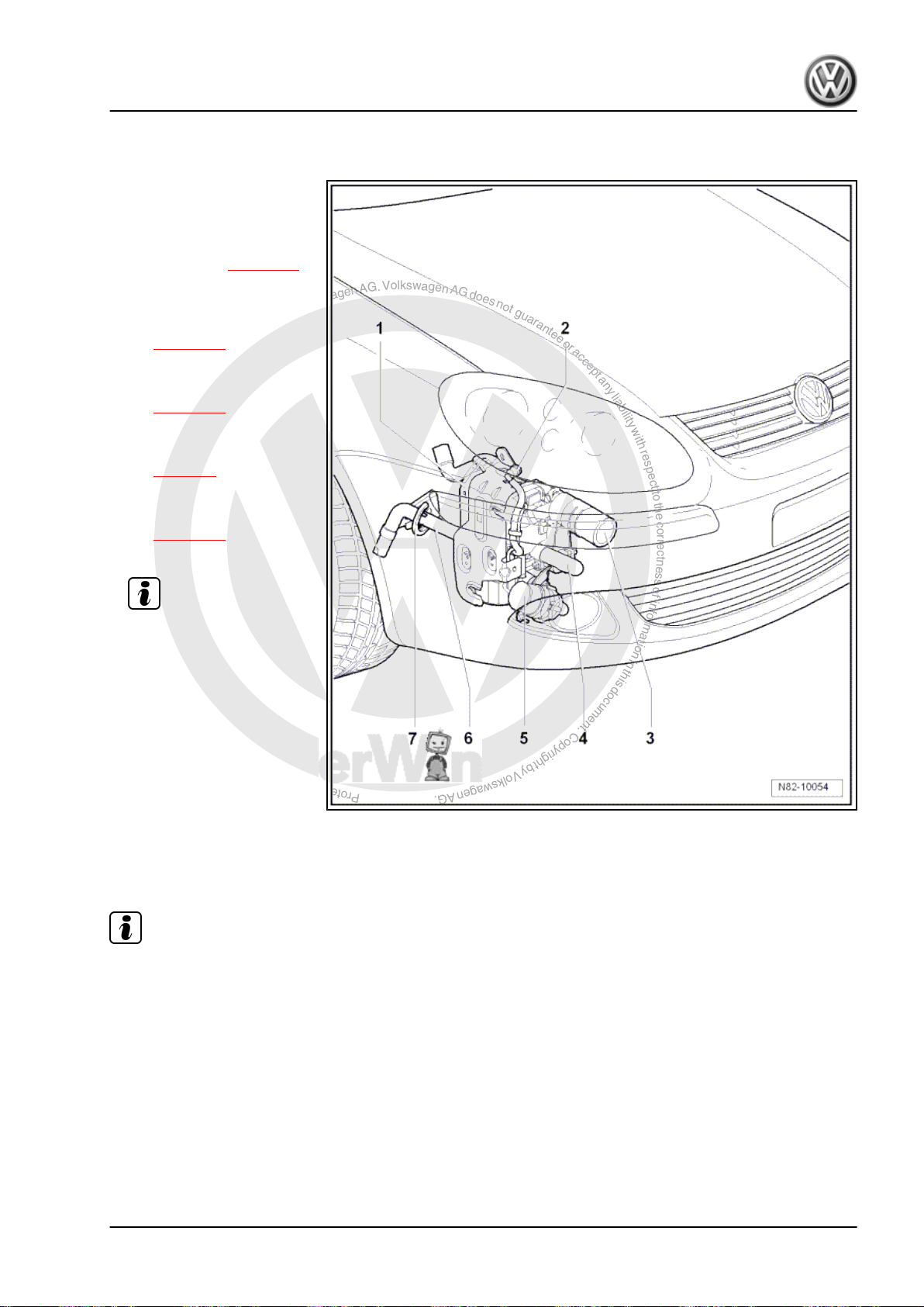
5.1 Components of auxiliary heater Thermo Top V
1 - Auxiliary heater Thermo
Top V
❑ With auxiliary heating
control unit -J364- .
❑ Removing ⇒ page 11
2 - Fuel line with quick-release
coupling
❑ Routing of fuel line
⇒ page 40 .
3 - Air intake silencer
❑ Removing and installing
4 - Exhaust system
❑ Removing and installing
5 - Circulation pump -V55-
❑ Removing and installing
6 - Exhaust pipe
7 - Chafing protection
⇒ page 14
⇒ page 8
⇒ page 15
Note
Golf 2004 ➤ , Golf 2009 ➤
5.2 Removing auxiliary heater Thermo Top V
Note
If the Thermo Top V is to be renewed, first connect vehicle diag‐
nosis, testing and information system -VAS 5051- (or later model)
and call up the “Renew heater” function under the guided func‐
tions.
Special tools and workshop equipment required
5. Removing and installing auxiliary heater Thermo Top V 11

P
r
o
t
e
c
t
e
d
b
y
c
o
p
y
r
i
g
h
t
.
C
o
p
y
i
n
g
f
o
r
p
r
i
v
a
t
e
o
r
c
o
m
m
e
r
c
i
a
l
p
u
r
p
o
s
e
s
,
i
n
p
a
r
t
o
r
i
n
w
h
o
l
e
,
i
s
n
o
t
p
e
r
m
i
t
t
e
d
u
n
l
e
s
s
a
u
t
h
o
r
i
s
e
d
b
y
V
o
l
k
s
w
a
g
e
n
A
G
.
V
o
l
k
s
w
a
g
e
n
A
G
d
o
e
s
n
o
t
g
u
a
r
a
n
t
e
e
o
r
a
c
c
e
p
t
a
n
y
l
i
a
b
i
l
i
t
y
w
i
t
h
r
e
s
p
e
c
t
t
o
t
h
e
c
o
r
r
e
c
t
n
e
s
s
o
f
i
n
f
o
r
m
a
t
i
o
n
i
n
t
h
i
s
d
o
c
u
m
e
n
t
.
C
o
p
y
r
i
g
h
t
b
y
V
o
l
k
s
w
a
g
e
n
A
G
.
Golf 2004 ➤ , Golf 2009 ➤
Auxiliary heater - Edition 09.2008
♦ Torque wrench -V.A.G 1410- (4…20 Nm)
♦ Hose clamps up to 25 mm Ø -3094-
♦ Vehicle diagnosis, testing and information system -VAS 5051-
or successor models.
Note
♦
The coolant circuit must be bled after it is opened
⇒ page 22 .
♦
After the auxiliary heater has been detached, it must be se‐
cured to the body with welding wire to prevent damage to the
coolant hoses.
– Remove lower front right wheel housing liner ⇒ Rep. Gr. 66 .
WARNING
Danger of burn injuries.
Parts of the exhaust system may be hot.
Before removing exhaust system, let it cool off.
12 Rep. Gr.82 - Auxiliary heating
P
r
o
t
e
c
t
e
d
b
y
c
o
p
y
r
i
g
h
t
.
C
o
p
y
i
n
g
f
o
r
p
r
i
v
a
t
e
o
r
c
o
m
m
e
r
c
i
a
l
p
u
r
p
o
s
e
s
,
i
n
p
a
r
t
o
r
i
n
w
h
o
l
e
,
i
s
n
o
t
p
e
r
m
i
t
t
e
d
u
n
l
e
s
s
a
u
t
h
o
r
i
s
e
d
b
y
V
o
l
k
s
w
a
g
e
n
A
G
.
V
o
l
k
s
w
a
g
e
n
A
G
d
o
e
s
n
o
t
g
u
a
r
a
n
t
e
e
o
r
a
c
c
e
p
t
a
n
y
l
i
a
b
i
l
i
t
y
w
i
t
h
r
e
s
p
e
c
t
t
o
t
h
e
c
o
r
r
e
c
t
n
e
s
s
o
f
i
n
f
o
r
m
a
t
i
o
n
i
n
t
h
i
s
d
o
c
u
m
e
n
t
.
C
o
p
y
r
i
g
h
t
b
y
V
o
l
k
s
w
a
g
e
n
A
G
.
– Remove exhaust pipe from silencer on auxiliary heater
⇒ page 15 .
WARNING
Danger of scalding injuries.
When the engine is warm, the coolant temperature may be
above 100 °C. The cooling system is pressurised.
If necessary, release pressure before carrying out repairs.
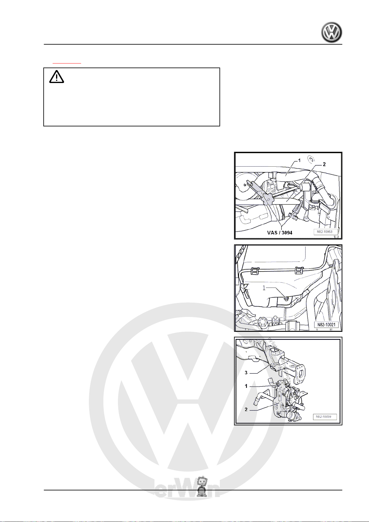
– Clamp off coolant hoses -1- and -2- using hose clamps up to
Ø 25 mm -3094- and pull coolant hoses off auxiliary heater.
Do not separate coolant hoses that are connected to each other.
– Remove fuel filter with bracket ⇒ Rep. Gr. 20 . On vehicles
with diesel engine.
Golf 2004 ➤ , Golf 2009 ➤
Auxiliary heater - Edition 09.2008
– Remove windscreen washer system reservoir ⇒ Rep. Gr. 92 .
– Remove securing bolt -1- (8 ± 0.8 Nm) below reservoir for
windscreen washer system.
– Remove securing nut -1- (8 ± 0.8 Nm) from auxiliary heater
-2- on right longitudinal member -3-.
5. Removing and installing auxiliary heater Thermo Top V 13

P
r
o
t
e
c
t
e
d
b
y
c
o
p
y
r
i
g
h
t
.
C
o
p
y
i
n
g
f
o
r
p
r
i
v
a
t
e
o
r
c
o
m
m
e
r
c
i
a
l
p
u
r
p
o
s
e
s
,
i
n
p
a
r
t
o
r
i
n
w
h
o
l
e
,
i
s
n
o
t
p
e
r
m
i
t
t
e
d
u
n
l
e
s
s
a
u
t
h
o
r
i
s
e
d
b
y
V
o
l
k
s
w
a
g
e
n
A
G
.
V
o
l
k
s
w
a
g
e
n
A
G
d
o
e
s
n
o
t
g
u
a
r
a
n
t
e
e
o
r
a
c
c
e
p
t
a
n
y
l
i
a
b
i
l
i
t
y
w
i
t
h
r
e
s
p
e
c
t
t
o
t
h
e
c
o
r
r
e
c
t
n
e
s
s
o
f
i
n
f
o
r
m
a
t
i
o
n
i
n
t
h
i
s
d
o
c
u
m
e
n
t
.
C
o
p
y
r
i
g
h
t
b
y
V
o
l
k
s
w
a
g
e
n
A
G
.
Golf 2004 ➤ , Golf 2009 ➤
Auxiliary heater - Edition 09.2008
– Remove securing nut -1- (15 ± 1.5 Nm) from auxiliary heater
-2- on right longitudinal member -3-.
WARNING
Danger of fuel escaping.
Fuel system is under pressure.
Before opening system, wrap a cloth around the connection.
Then release pressure by carefully loosening the connection.
– Disconnect fuel line at quick-release coupling and seal fuel
lines with appropriate plugs.
Caution
Auxiliary heater control unit -J364- could get damaged.
Overvoltages can occur at the connectors.
First pull out 8-pin connector.
– Unplug the other connectors at the auxiliary heater.
5.3 Installing auxiliary heater Thermo Top V
Note
If the Thermo Top V is not to be renewed, connect vehicle diag‐
nosis, testing and information system -VAS 5051- (or later model)
and call up the “Release heater” function under the guided func‐
tions.
Installation is carried out in the reverse order. When installing,
note the following:
– After installing auxiliary heater, bleed coolant circuit
⇒ page 22 .
– Then start the auxiliary heater.
5.4 Removing ancillaries of auxiliary heater Thermo Top V
5.4.1 Removing air intake silencer
– Unclip air intake silencer -1- from bracket -2- and pull off intake
pipe -3-.
14 Rep. Gr.82 - Auxiliary heating

P
r
o
t
e
c
t
e
d
b
y
c
o
p
y
r
i
g
h
t
.
C
o
p
y
i
n
g
f
o
r
p
r
i
v
a
t
e
o
r
c
o
m
m
e
r
c
i
a
l
p
u
r
p
o
s
e
s
,
i
n
p
a
r
t
o
r
i
n
w
h
o
l
e
,
i
s
n
o
t
p
e
r
m
i
t
t
e
d
u
n
l
e
s
s
a
u
t
h
o
r
i
s
e
d
b
y
V
o
l
k
s
w
a
g
e
n
A
G
.
V
o
l
k
s
w
a
g
e
n
A
G
d
o
e
s
n
o
t
g
u
a
r
a
n
t
e
e
o
r
a
c
c
e
p
t
a
n
y
l
i
a
b
i
l
i
t
y
w
i
t
h
r
e
s
p
e
c
t
t
o
t
h
e
c
o
r
r
e
c
t
n
e
s
s
o
f
i
n
f
o
r
m
a
t
i
o
n
i
n
t
h
i
s
d
o
c
u
m
e
n
t
.
C
o
p
y
r
i
g
h
t
b
y
V
o
l
k
s
w
a
g
e
n
A
G
.
5.4.2 Installing
– Push air intake silencer onto intake pipe -3- far enough that it
can be clipped into bracket -2-.
5.4.3 Removing circulation pump -V55-
Special tools and workshop equipment required
♦ Hose clamps up to 25 mm Ø -3094-
– Clamp off coolant hoses using hose clamps up to 25 mm Ø
-3094- .
– Loosen clip -1-.
Danger of scalding injuries.
When the engine is warm, the coolant temperature may be
above 100 °C. The cooling system is pressurised.
If necessary, release pressure before carrying out repairs.
– Pull coolant hoses off circulation pump -V55- .
– Pull connector off circulation pump -V55- .
– Remove bolt -2- and remove circulation pump -V55- .
WARNING
Golf 2004 ➤ , Golf 2009 ➤
Auxiliary heater - Edition 09.2008
5.4.4 Installing
Installation is carried out in the reverse order. When installing,
note the following:
– After installing circulation pump -V55- , bleed coolant circuit
⇒ page 22 .
5.4.5 Removing and installing exhaust pipe for auxiliary heater
Short exhaust pipe
WARNING
Danger of burn injuries.
Parts of the exhaust system may be hot.
Before removing exhaust system, let it cool off.
5. Removing and installing auxiliary heater Thermo Top V 15

P
r
o
t
e
c
t
e
d
b
y
c
o
p
y
r
i
g
h
t
.
C
o
p
y
i
n
g
f
o
r
p
r
i
v
a
t
e
o
r
c
o
m
m
e
r
c
i
a
l
p
u
r
p
o
s
e
s
,
i
n
p
a
r
t
o
r
i
n
w
h
o
l
e
,
i
s
n
o
t
p
e
r
m
i
t
t
e
d
u
n
l
e
s
s
a
u
t
h
o
r
i
s
e
d
b
y
V
o
l
k
s
w
a
g
e
n
A
G
.
V
o
l
k
s
w
a
g
e
n
A
G
d
o
e
s
n
o
t
g
u
a
r
a
n
t
e
e
o
r
a
c
c
e
p
t
a
n
y
l
i
a
b
i
l
i
t
y
w
i
t
h
r
e
s
p
e
c
t
t
o
t
h
e
c
o
r
r
e
c
t
n
e
s
s
o
f
i
n
f
o
r
m
a
t
i
o
n
i
n
t
h
i
s
d
o
c
u
m
e
n
t
.
C
o
p
y
r
i
g
h
t
b
y
V
o
l
k
s
w
a
g
e
n
A
G
.
Golf 2004 ➤ , Golf 2009 ➤
Auxiliary heater - Edition 09.2008
– Remove nut and bolt -1-. When installing, first tighten bolt (6
±0.6 Nm).
Long exhaust pipe
– Remove nuts and bolt -1-. When installing, first tighten bolt (6
±0.6 Nm).
– When installing exhaust system, first install this exhaust pipe.
Note
Observe drain hole -arrow-. It must be visible following installation
and also serves as an installation marking.
– Tighten bolts and nuts to 6 ±0.6 Nm and bolt -2- to 23 ±3.5
Nm. Tightening sequence of bolts and nuts is 1...4.
16 Rep. Gr.82 - Auxiliary heating
 Loading...