

Page 1
P
r
o
t
e
c
t
e
d
b
y
c
o
p
y
r
i
g
h
t
.
C
o
p
y
i
n
g
f
o
r
p
r
i
v
a
t
e
o
r
c
o
m
m
e
r
c
i
a
l
p
u
r
p
o
s
e
s
,
i
n
p
a
r
t
o
r
i
n
w
h
o
l
e
,
i
s
n
o
t
p
e
r
m
i
t
t
e
d
u
n
l
e
s
s
a
u
t
h
o
r
i
s
e
d
b
y
V
o
l
k
s
w
a
g
e
n
A
G
.
V
o
l
k
s
w
a
g
e
n
A
G
d
o
e
s
n
o
t
g
u
a
r
a
n
t
e
e
o
r
a
c
c
e
p
t
a
n
y
l
i
a
b
i
l
i
t
y
w
i
t
h
r
e
s
p
e
c
t
t
o
t
h
e
c
o
r
r
e
c
t
n
e
s
s
o
f
i
n
f
o
r
m
a
t
i
o
n
i
n
t
h
i
s
d
o
c
u
m
e
n
t
.
C
o
p
y
r
i
g
h
t
b
y
V
o
l
k
s
w
a
g
e
n
A
G
.
Service
Workshop Manual
Golf Variant 2007 ➤
Golf Variant 2010 ➤
Jetta 2005 ➤
Jetta 2011 ➤
Heating, air conditioning
Edition 04.2010
Service Department. Technical Information
Page 2

P
r
o
t
e
c
t
e
d
b
y
c
o
p
y
r
i
g
h
t
.
C
o
p
y
i
n
g
f
o
r
p
r
i
v
a
t
e
o
r
c
o
m
m
e
r
c
i
a
l
p
u
r
p
o
s
e
s
,
i
n
p
a
r
t
o
r
i
n
w
h
o
l
e
,
i
s
n
o
t
p
e
r
m
i
t
t
e
d
u
n
l
e
s
s
a
u
t
h
o
r
i
s
e
d
b
y
V
o
l
k
s
w
a
g
e
n
A
G
.
V
o
l
k
s
w
a
g
e
n
A
G
d
o
e
s
n
o
t
g
u
a
r
a
n
t
e
e
o
r
a
c
c
e
p
t
a
n
y
l
i
a
b
i
l
i
t
y
w
i
t
h
r
e
s
p
e
c
t
t
o
t
h
e
c
o
r
r
e
c
t
n
e
s
s
o
f
i
n
f
o
r
m
a
t
i
o
n
i
n
t
h
i
s
d
o
c
u
m
e
n
t
.
C
o
p
y
r
i
g
h
t
b
y
V
o
l
k
s
w
a
g
e
n
A
G
.
Service
List of Workshop Manual Repair GroupsList of Workshop Manual
Repair GroupsList of Workshop Manual Repair Groups
Re pa ir G ro up
80 - Heating
87 - Air conditioning system
Technical information should always be available to the foremen and mechanics, because their
careful and constant adherence to the instructions is essential to ensure vehicle road-worthiness and
safety. In addition, the normal basic safety precautions for working on motor vehicles must, as a
matter of course, be observed.
All rights reserved.
No reproduction without prior agreement from publisher.
Copyright © 2010 Volkswagen AG, Wolfsburg MEX5R006020
Page 3

P
r
o
t
e
c
t
e
d
b
y
c
o
p
y
r
i
g
h
t
.
C
o
p
y
i
n
g
f
o
r
p
r
i
v
a
t
e
o
r
c
o
m
m
e
r
c
i
a
l
p
u
r
p
o
s
e
s
,
i
n
p
a
r
t
o
r
i
n
w
h
o
l
e
,
i
s
n
o
t
p
e
r
m
i
t
t
e
d
u
n
l
e
s
s
a
u
t
h
o
r
i
s
e
d
b
y
V
o
l
k
s
w
a
g
e
n
A
G
.
V
o
l
k
s
w
a
g
e
n
A
G
d
o
e
s
n
o
t
g
u
a
r
a
n
t
e
e
o
r
a
c
c
e
p
t
a
n
y
l
i
a
b
i
l
i
t
y
w
i
t
h
r
e
s
p
e
c
t
t
o
t
h
e
c
o
r
r
e
c
t
n
e
s
s
o
f
i
n
f
o
r
m
a
t
i
o
n
i
n
t
h
i
s
d
o
c
u
m
e
n
t
.
C
o
p
y
r
i
g
h
t
b
y
V
o
l
k
s
w
a
g
e
n
A
G
.
Golf Variant 2007 ➤ , Golf Variant 2010 ➤ , Jetta 2005 ➤ , Jetta 2011 ➤
Heating, air conditioning - Edition 04.2010
Contents
80 - Heating . . . . . . . . . . . . . . . . . . . . . . . . . . . . . . . . . . . . . . . . . . . . . . . . . . . . . . . . . . 1
1 Repairing heating system . . . . . . . . . . . . . . . . . . . . . . . . . . . . . . . . . . . . . . . . . . . . . . . . . . 1
1.1 Heater - passenger compartment (Golf Variant 2007►, Golf Variant 2010► und Jetta
2005►) . . . . . . . . . . . . . . . . . . . . . . . . . . . . . . . . . . . . . . . . . . . . . . . . . . . . . . . . . . . . . . . . 1
1.2 Heater - passenger compartment (Jetta 2011►) . . . . . . . . . . . . . . . . . . . . . . . . . . . . . . . . 4
1.3 Removing fresh air blower V2 . . . . . . . . . . . . . . . . . . . . . . . . . . . . . . . . . . . . . . . . . . . . . . 5
1.4 Removing and installing fresh air blower series resistor with overheating fuse N24 . . . . . . 6
1.5 Removing and installing dust and pollen filter . . . . . . . . . . . . . . . . . . . . . . . . . . . . . . . . . . 6
1.6 Removing vent (Golf Variant 2007►, Golf Variant 2010► und Jetta 2005►) . . . . . . . . . . . . 7
1.7 Removing vent (Jetta 2011►) . . . . . . . . . . . . . . . . . . . . . . . . . . . . . . . . . . . . . . . . . . . . . . . . 10
1.8 Removing and installing controls for heated and fresh air . . . . . . . . . . . . . . . . . . . . . . . . . . 14
1.9 Connectors on controls for heated and fresh air (Golf Variant 2007►, Golf Variant 2010► und
Jetta 2005►) . . . . . . . . . . . . . . . . . . . . . . . . . . . . . . . . . . . . . . . . . . . . . . . . . . . . . . . . . . . . 15
1.10 Connectors on controls for heated and fresh air (Jetta 2011►) . . . . . . . . . . . . . . . . . . . . . . 16
1.11 Removing and installing flexible shaft for air distribution . . . . . . . . . . . . . . . . . . . . . . . . . . 17
1.12 Removing and installing Bowden cable for temperature flap . . . . . . . . . . . . . . . . . . . . . . . . 18
1.13 Removing and installing fresh air and air recirculation flap control motor V154 . . . . . . . . 19
1.14 Removing and installing heat exchanger (Golf Variant 2007►, Golf Variant 2010► und Jetta
2005►) . . . . . . . . . . . . . . . . . . . . . . . . . . . . . . . . . . . . . . . . . . . . . . . . . . . . . . . . . . . . . . . . 19
1.15 Removing and installing heat exchanger (Jetta 2010►) . . . . . . . . . . . . . . . . . . . . . . . . . . . . 23
1.16 Removing and installing auxiliary air heater element Z35 , vehicles ► 1K-7M 119 726 . . . . 26
1.17 Checking, removing and installing auxiliary air heater element Z35 , vehicles 1K-7M 119 727
► . . . . . . . . . . . . . . . . . . . . . . . . . . . . . . . . . . . . . . . . . . . . . . . . . . . . . . . . . . . . . . . . . . . . . . 27
1.18 Checking ventilation . . . . . . . . . . . . . . . . . . . . . . . . . . . . . . . . . . . . . . . . . . . . . . . . . . . . . . 29
1.19 Removing and installing air intake grille (Golf Variant 2007►, Golf Variant 2010► und Jetta
2005►) . . . . . . . . . . . . . . . . . . . . . . . . . . . . . . . . . . . . . . . . . . . . . . . . . . . . . . . . . . . . . . . . 30
1.20 Removing and installing air intake grille (Jetta 2010►) . . . . . . . . . . . . . . . . . . . . . . . . . . . . 30
1.21 Removing and installing heater unit . . . . . . . . . . . . . . . . . . . . . . . . . . . . . . . . . . . . . . . . . . 31
2 Dismantling and assembling heater unit . . . . . . . . . . . . . . . . . . . . . . . . . . . . . . . . . . . . . . 35
2.1 Dismantling and assembling heater unit . . . . . . . . . . . . . . . . . . . . . . . . . . . . . . . . . . . . . . 35
2.2 Removing and installing air distribution flap actuator . . . . . . . . . . . . . . . . . . . . . . . . . . . . . . 36
2.3 Removing and installing temperature flap actuator . . . . . . . . . . . . . . . . . . . . . . . . . . . . . . 36
87 - Air conditioning system . . . . . . . . . . . . . . . . . . . . . . . . . . . . . . . . . . . . . . . . . . . . 38
1 Notes on repair work to vehicles with air conditioning and on handling refrigerant . . . . . . 38
2 Air conditioning system with manual controls, Climatic . . . . . . . . . . . . . . . . . . . . . . . . . . . . 39
2.1 Air conditioning system and heater - passenger compartment (Golf Variant 2007►, Golf
Variant 2010► und Jetta 2005►) . . . . . . . . . . . . . . . . . . . . . . . . . . . . . . . . . . . . . . . . . . . . . . 39
2.2 Air conditioning system and heater - passenger compartment (Jetta 2011►) . . . . . . . . . . 41
2.3 Removing and installing heater and air conditioner unit (Climatic) . . . . . . . . . . . . . . . . . . 42
2.4 Dismantling and assembling heater and air conditioning unit (Climatic) . . . . . . . . . . . . . . 47
2.5 Removing and installing heating and air conditioning controls, Climatic . . . . . . . . . . . . . . 48
2.6 Connections on controls for heating and air conditioning, Climatic . . . . . . . . . . . . . . . . . . 49
2.7 Removing and installing flexible shaft . . . . . . . . . . . . . . . . . . . . . . . . . . . . . . . . . . . . . . . . 50
2.8 Checking condensation water drainage hose on heater and air conditioner unit . . . . . . . . 51
2.9 Removing and installing air recirculation flap control motor V113 . . . . . . . . . . . . . . . . . . . . 51
2.10 Removing and installing temperature flap control motor V68 . . . . . . . . . . . . . . . . . . . . . . 51
2.11 Removing and installing footwell vent temperature sender G192 . . . . . . . . . . . . . . . . . . . . 53
2.12 Removing and installing centre vent temperature sender G191 . . . . . . . . . . . . . . . . . . . . 54
3 Climatronic air conditioning with automatic regulation . . . . . . . . . . . . . . . . . . . . . . . . . . . . 55
3.1 Procedure for checking and adjusting components . . . . . . . . . . . . . . . . . . . . . . . . . . . . . . 55
3.2 Function of operating and display unit for Climatronic air conditioning system E87 (Golf
Variant 2007►, Golf Variant 2010► und Jetta 2005►) . . . . . . . . . . . . . . . . . . . . . . . . . . . . 56
Contents i
Page 4

P
r
o
t
e
c
t
e
d
b
y
c
o
p
y
r
i
g
h
t
.
C
o
p
y
i
n
g
f
o
r
p
r
i
v
a
t
e
o
r
c
o
m
m
e
r
c
i
a
l
p
u
r
p
o
s
e
s
,
i
n
p
a
r
t
o
r
i
n
w
h
o
l
e
,
i
s
n
o
t
p
e
r
m
i
t
t
e
d
u
n
l
e
s
s
a
u
t
h
o
r
i
s
e
d
b
y
V
o
l
k
s
w
a
g
e
n
A
G
.
V
o
l
k
s
w
a
g
e
n
A
G
d
o
e
s
n
o
t
g
u
a
r
a
n
t
e
e
o
r
a
c
c
e
p
t
a
n
y
l
i
a
b
i
l
i
t
y
w
i
t
h
r
e
s
p
e
c
t
t
o
t
h
e
c
o
r
r
e
c
t
n
e
s
s
o
f
i
n
f
o
r
m
a
t
i
o
n
i
n
t
h
i
s
d
o
c
u
m
e
n
t
.
C
o
p
y
r
i
g
h
t
b
y
V
o
l
k
s
w
a
g
e
n
A
G
.
Golf Variant 2007 ➤ , Golf Variant 2010 ➤ , Jetta 2005 ➤ , Jetta 2011 ➤
Heating, air conditioning - Edition 04.2010
3.3 Removing and installing operating and display unit for Climatronic air conditioning system
E87 with Climatronic control unit J255 (Golf Variant 2007►, Golf Variant 2010► und Jetta
2005►) . . . . . . . . . . . . . . . . . . . . . . . . . . . . . . . . . . . . . . . . . . . . . . . . . . . . . . . . . . . . . . . . 57
3.4 Function of operating and display unit for Climatronic air conditioning system E87 (Jetta
2011►) . . . . . . . . . . . . . . . . . . . . . . . . . . . . . . . . . . . . . . . . . . . . . . . . . . . . . . . . . . . . . . . . 57
3.5 Removing and installing operating and display unit for Climatronic air conditioning system
E87 with Climatronic control unit J255 (Jetta 2011►) . . . . . . . . . . . . . . . . . . . . . . . . . . . . . . 59
3.6 Connectors on Climatronic control unit J255 . . . . . . . . . . . . . . . . . . . . . . . . . . . . . . . . . . . . 59
3.7 Climatronic - passenger compartment (Golf Variant 2007►, Golf Variant 2010► und Jetta
3.8 Climatronic - passenger compartment (Jetta 2011►) . . . . . . . . . . . . . . . . . . . . . . . . . . . . . . 65
3.9 Removing and installing fresh air blower control unit J126 . . . . . . . . . . . . . . . . . . . . . . . . 67
3.10 Removing and installing heater and air conditioning unit (Climatronic) . . . . . . . . . . . . . . . . 68
3.11 Dismantling and assembling heater and air conditioning unit (Golf Variant 2007►, Golf Variant
3.12 Dismantling and assembling heater and air conditioning unit (Jetta 2011►) . . . . . . . . . . . . 73
3.13 Dismantling and assembling evaporator housing . . . . . . . . . . . . . . . . . . . . . . . . . . . . . . . . 75
3.14 Removing and installing left footwell vent temperature sender G261 . . . . . . . . . . . . . . . . 76
3.15 Removing and installing right footwell vent temperature sender G262 . . . . . . . . . . . . . . . . 77
3.16 Removing and installing evaporator temperature sensor G308 . . . . . . . . . . . . . . . . . . . . 77
3.17 Removing left vent temperature sender G150 and right vent temperature sender G151 . . 78
3.18 Removing sunlight penetration photosensor G107 or sunlight penetration photosensor 2
2005►) . . . . . . . . . . . . . . . . . . . . . . . . . . . . . . . . . . . . . . . . . . . . . . . . . . . . . . . . . . . . . . . . 61
2010► und Jetta 2005►) . . . . . . . . . . . . . . . . . . . . . . . . . . . . . . . . . . . . . . . . . . . . . . . . . . . . 71
G134 . . . . . . . . . . . . . . . . . . . . . . . . . . . . . . . . . . . . . . . . . . . . . . . . . . . . . . . . . . . . . . . . . . 78
3.19 Checking condensation water drainage hose on heater and air conditioner unit . . . . . . . . 79
3.20 Renewing control motors for air conditioning regulation . . . . . . . . . . . . . . . . . . . . . . . . . . 79
3.21 Removing and installing fresh air and air recirculation flap control motor V154 . . . . . . . . 79
3.22 Removing and installing air flow flap control motor V71 or fresh air/recirculated air, air flow
flap control motor V425 . . . . . . . . . . . . . . . . . . . . . . . . . . . . . . . . . . . . . . . . . . . . . . . . . . . . 79
3.23 Removing and installing defroster flap control motor V107 . . . . . . . . . . . . . . . . . . . . . . . . 80
3.24 Removing and installing left temperature flap control motor V158 . . . . . . . . . . . . . . . . . . 81
3.25 Removing and installing right temperature flap control motor V159 . . . . . . . . . . . . . . . . . . 82
3.26 Removing and installing central flap control motor V70 . . . . . . . . . . . . . . . . . . . . . . . . . . 83
4 Ancillary bracket for air conditioner compressor . . . . . . . . . . . . . . . . . . . . . . . . . . . . . . . . 84
4.1 Removing and installing ancillary bracket for air conditioner compressor (Jetta 2011►) . . 84
4.2 Removing and installing ancillary bracket for air conditioner compressor, engine codes BRM
and BXE . . . . . . . . . . . . . . . . . . . . . . . . . . . . . . . . . . . . . . . . . . . . . . . . . . . . . . . . . . . . . . . . 84
4.3 Removing and installing ancillary bracket for air conditioner compressor, engine codes BGP
and BGQ . . . . . . . . . . . . . . . . . . . . . . . . . . . . . . . . . . . . . . . . . . . . . . . . . . . . . . . . . . . . . . 86
4.4 Removing and installing ancillary bracket for air conditioner compressor, engine codes BPY,
BWA, BSE, BSF, BLR, BLY . . . . . . . . . . . . . . . . . . . . . . . . . . . . . . . . . . . . . . . . . . . . . . . . 88
5 Repair work on refrigerant circuit which may be performed only in appropriate workshops by
specially trained mechanics . . . . . . . . . . . . . . . . . . . . . . . . . . . . . . . . . . . . . . . . . . . . . . . . 91
5.1 Testing equipment and tools . . . . . . . . . . . . . . . . . . . . . . . . . . . . . . . . . . . . . . . . . . . . . . . . 91
5.2 Renewing refrigerant circuit components . . . . . . . . . . . . . . . . . . . . . . . . . . . . . . . . . . . . . . 92
5.3 Removing high-pressure sender G65 (Golf Variant 2007►, Golf Variant 2010► und Jetta
2005►) . . . . . . . . . . . . . . . . . . . . . . . . . . . . . . . . . . . . . . . . . . . . . . . . . . . . . . . . . . . . . . . . 94
5.4 Removing high-pressure sender G65 (Jetta 2011►) . . . . . . . . . . . . . . . . . . . . . . . . . . . . . . 95
5.5 Removing and installing receiver with dryer cartridge . . . . . . . . . . . . . . . . . . . . . . . . . . . . 95
5.6 Removing and installing air conditioner compressor . . . . . . . . . . . . . . . . . . . . . . . . . . . . . . 96
5.7 Checking high-pressure safety valve on air conditioner compressor . . . . . . . . . . . . . . . . . . 97
5.8 Expansion valve, function and removing . . . . . . . . . . . . . . . . . . . . . . . . . . . . . . . . . . . . . . 98
5.9 Removing and installing evaporator . . . . . . . . . . . . . . . . . . . . . . . . . . . . . . . . . . . . . . . . . . 99
5.10 Removing and installing condenser (Golf Variant 2007►, Golf Variant 2010► und Jetta
2005►) . . . . . . . . . . . . . . . . . . . . . . . . . . . . . . . . . . . . . . . . . . . . . . . . . . . . . . . . . . . . . . . . 100
5.11 Removing and installing condenser (Jetta 2010►) . . . . . . . . . . . . . . . . . . . . . . . . . . . . . . . . 102
5.12 Notes on installing air conditioner compressor . . . . . . . . . . . . . . . . . . . . . . . . . . . . . . . . . . 103
6 Capacities . . . . . . . . . . . . . . . . . . . . . . . . . . . . . . . . . . . . . . . . . . . . . . . . . . . . . . . . . . . . . . 105
6.1 Refrigerant R134a . . . . . . . . . . . . . . . . . . . . . . . . . . . . . . . . . . . . . . . . . . . . . . . . . . . . . . . . 105
ii Contents
Page 5

P
r
o
t
e
c
t
e
d
b
y
c
o
p
y
r
i
g
h
t
.
C
o
p
y
i
n
g
f
o
r
p
r
i
v
a
t
e
o
r
c
o
m
m
e
r
c
i
a
l
p
u
r
p
o
s
e
s
,
i
n
p
a
r
t
o
r
i
n
w
h
o
l
e
,
i
s
n
o
t
p
e
r
m
i
t
t
e
d
u
n
l
e
s
s
a
u
t
h
o
r
i
s
e
d
b
y
V
o
l
k
s
w
a
g
e
n
A
G
.
V
o
l
k
s
w
a
g
e
n
A
G
d
o
e
s
n
o
t
g
u
a
r
a
n
t
e
e
o
r
a
c
c
e
p
t
a
n
y
l
i
a
b
i
l
i
t
y
w
i
t
h
r
e
s
p
e
c
t
t
o
t
h
e
c
o
r
r
e
c
t
n
e
s
s
o
f
i
n
f
o
r
m
a
t
i
o
n
i
n
t
h
i
s
d
o
c
u
m
e
n
t
.
C
o
p
y
r
i
g
h
t
b
y
V
o
l
k
s
w
a
g
e
n
A
G
.
Golf Variant 2007 ➤ , Golf Variant 2010 ➤ , Jetta 2005 ➤ , Jetta 2011 ➤
Heating, air conditioning - Edition 04.2010
6.2 Refrigerant oil . . . . . . . . . . . . . . . . . . . . . . . . . . . . . . . . . . . . . . . . . . . . . . . . . . . . . . . . . . . . 105
Contents iii
Page 6

P
r
o
t
e
c
t
e
d
b
y
c
o
p
y
r
i
g
h
t
.
C
o
p
y
i
n
g
f
o
r
p
r
i
v
a
t
e
o
r
c
o
m
m
e
r
c
i
a
l
p
u
r
p
o
s
e
s
,
i
n
p
a
r
t
o
r
i
n
w
h
o
l
e
,
i
s
n
o
t
p
e
r
m
i
t
t
e
d
u
n
l
e
s
s
a
u
t
h
o
r
i
s
e
d
b
y
V
o
l
k
s
w
a
g
e
n
A
G
.
V
o
l
k
s
w
a
g
e
n
A
G
d
o
e
s
n
o
t
g
u
a
r
a
n
t
e
e
o
r
a
c
c
e
p
t
a
n
y
l
i
a
b
i
l
i
t
y
w
i
t
h
r
e
s
p
e
c
t
t
o
t
h
e
c
o
r
r
e
c
t
n
e
s
s
o
f
i
n
f
o
r
m
a
t
i
o
n
i
n
t
h
i
s
d
o
c
u
m
e
n
t
.
C
o
p
y
r
i
g
h
t
b
y
V
o
l
k
s
w
a
g
e
n
A
G
.
Golf Variant 2007 ➤ , Golf Variant 2010 ➤ , Jetta 2005 ➤ , Jetta 2011 ➤
Heating, air conditioning - Edition 04.2010
iv Contents
Page 7
P
r
o
t
e
c
t
e
d
b
y
c
o
p
y
r
i
g
h
t
.
C
o
p
y
i
n
g
f
o
r
p
r
i
v
a
t
e
o
r
c
o
m
m
e
r
c
i
a
l
p
u
r
p
o
s
e
s
,
i
n
p
a
r
t
o
r
i
n
w
h
o
l
e
,
i
s
n
o
t
p
e
r
m
i
t
t
e
d
u
n
l
e
s
s
a
u
t
h
o
r
i
s
e
d
b
y
V
o
l
k
s
w
a
g
e
n
A
G
.
V
o
l
k
s
w
a
g
e
n
A
G
d
o
e
s
n
o
t
g
u
a
r
a
n
t
e
e
o
r
a
c
c
e
p
t
a
n
y
l
i
a
b
i
l
i
t
y
w
i
t
h
r
e
s
p
e
c
t
t
o
t
h
e
c
o
r
r
e
c
t
n
e
s
s
o
f
i
n
f
o
r
m
a
t
i
o
n
i
n
t
h
i
s
d
o
c
u
m
e
n
t
.
C
o
p
y
r
i
g
h
t
b
y
V
o
l
k
s
w
a
g
e
n
A
G
.
Golf Variant 2007 ➤ , Golf Variant 2010 ➤ , Jetta 2005 ➤ , Jetta 2011 ➤
Heating, air conditioning - Edition 04.2010
80 – Heating
1 Repairing heating system
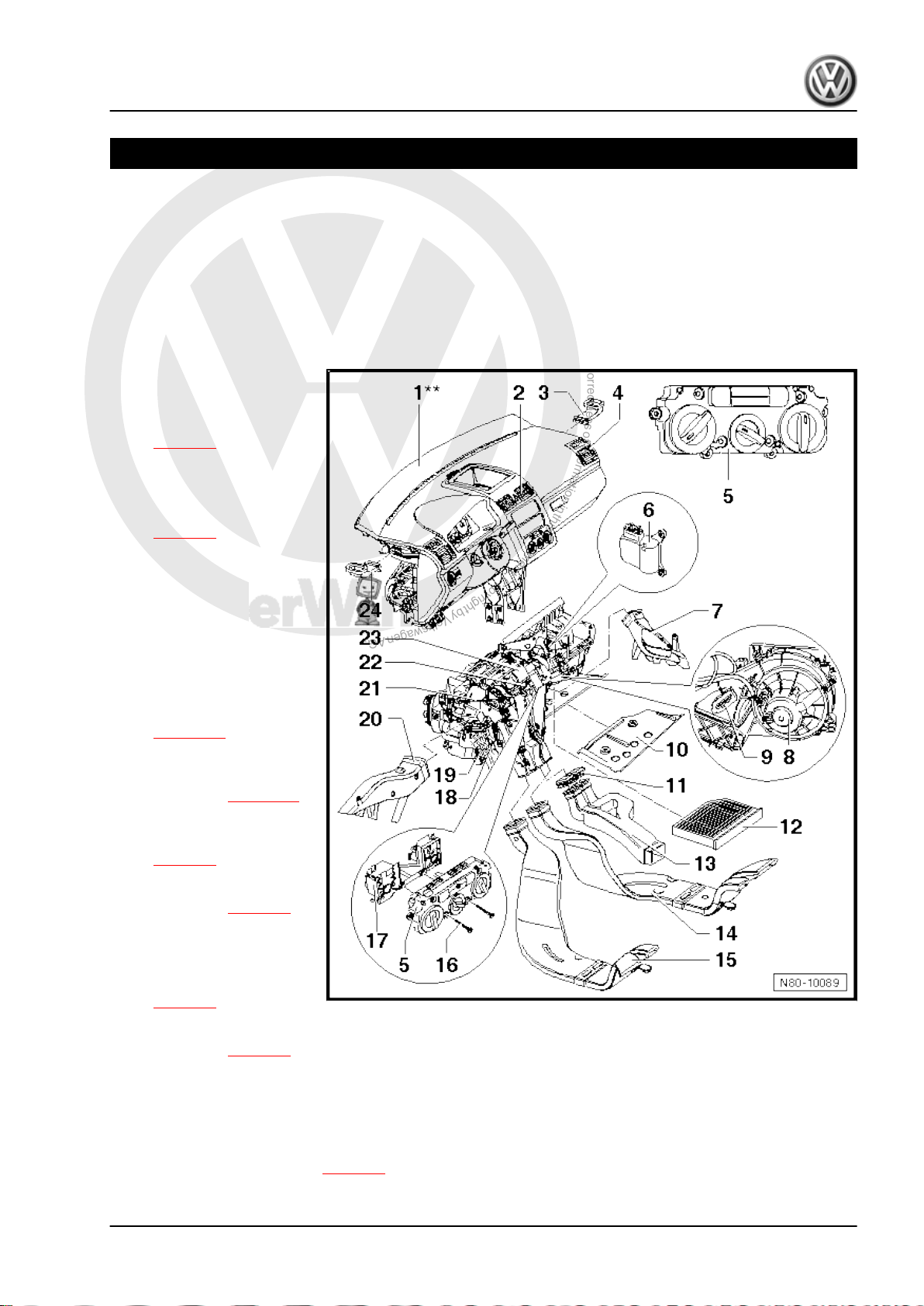
1.1 Heater - passenger compartment (Golf Variant 2007►, Golf Variant 2010►
Disconnect battery before removing components marked ** ⇒
Rep. gr. 27 .
1 - Dash panel**
2 - Centre vents
❑ Removing vent
⇒ page 7 .
3 - Right side vent
4 - Right vent
❑ Removing vent
⇒ page 8 .
5 - Controls for fresh and heat‐
ed air
❑ With fresh air and air re‐
circulation flap switch E159- .
und Jetta 2005►)
❑ For vehicles with sup‐
plementary heating hav‐
ing instant heating but‐
ton -E537- .
❑ Removing controls
⇒ page 14 .
6 - Fresh air and air recircula‐
tion flap control motor -V154-
❑ Removing ⇒ page 19
7 - Right footwell vent
❑ Removing and installing
⇒ page 9
8 - Fresh air blower -V2-
❑ Removing ⇒ page 5
9 - Fresh air blower series re‐
sistor with overheating fuse N24-
❑ Removing and installing
⇒ page 6
10 - Baffle plate for heater unit
❑ Removing ⇒ page 3
11 - Sealing cap
❑ Fitted only in vehicles without air duct to vent in rear centre console.
12 - Dust and pollen filter
❑ With activated charcoal filter
❑ Removing and installing ⇒ page 6
1. Repairing heating system 1
Page 8
P
r
o
t
e
c
t
e
d
b
y
c
o
p
y
r
i
g
h
t
.
C
o
p
y
i
n
g
f
o
r
p
r
i
v
a
t
e
o
r
c
o
m
m
e
r
c
i
a
l
p
u
r
p
o
s
e
s
,
i
n
p
a
r
t
o
r
i
n
w
h
o
l
e
,
i
s
n
o
t
p
e
r
m
i
t
t
e
d
u
n
l
e
s
s
a
u
t
h
o
r
i
s
e
d
b
y
V
o
l
k
s
w
a
g
e
n
A
G
.
V
o
l
k
s
w
a
g
e
n
A
G
d
o
e
s
n
o
t
g
u
a
r
a
n
t
e
e
o
r
a
c
c
e
p
t
a
n
y
l
i
a
b
i
l
i
t
y
w
i
t
h
r
e
s
p
e
c
t
t
o
t
h
e
c
o
r
r
e
c
t
n
e
s
s
o
f
i
n
f
o
r
m
a
t
i
o
n
i
n
t
h
i
s
d
o
c
u
m
e
n
t
.
C
o
p
y
r
i
g
h
t
b
y
V
o
l
k
s
w
a
g
e
n
A
G
.
Golf Variant 2007 ➤ , Golf Variant 2010 ➤ , Jetta 2005 ➤ , Jetta 2011 ➤
Heating, air conditioning - Edition 04.2010
13 - Connecting piece
❑ For centre console air duct.
❑ To remove, centre console must be removed ⇒ Rep. gr. 68 .
14 - Air duct for right rear footwell
❑ Removing and installing ⇒ page 8
15 - Air duct for left rear footwell
❑ Removing and installing ⇒ page 8
16 - Securing bolt
❑ Qty. 8
❑ Various lengths.
17 - Adapter for controls
❑ Removing and installing ⇒ page 18
18 - Auxiliary air heater element -Z35-
Vehicles ► 1K-7M 119 726
❑ With auxiliary air heater control unit -J604- .
❑ Checking: with vehicle diagnosis, testing and information system -VAS 5051- (or later model), under
Heating, ventilation, air conditioning; Systems capable of self-diagnosis; Auxiliary heating; Electrical
components.
❑ Removing and installing ⇒ page 26
Vehicles 1K-7M 119 726 ►
❑ A 3-speed auxiliary air heater element -Z35- is fitted here; it is controlled by the respective engine control
unit via relays.
❑ Installed only in vehicles with diesel engines without supplementary heater.
❑ Removing and installing ⇒ page 27
19 - Heat exchanger
❑ After renewing heat exchanger, renew coolant completely ⇒ Rep. gr. 19 .
❑ Removing and installing ⇒ page 19
20 - Left footwell vent
❑ Removing and installing ⇒ page 9
21 - Bowden cable for temperature flap
❑ Removing and installing ⇒ page 18
22 - Flexible shaft
❑ Removing and installing ⇒ page 17
23 - Heater unit
❑ Removing and installing ⇒ page 31
❑ Dismantling and assembling ⇒ page 35
24 - Left side vent
2 Rep. gr.80 - Heating
Page 9
P
r
o
t
e
c
t
e
d
b
y
c
o
p
y
r
i
g
h
t
.
C
o
p
y
i
n
g
f
o
r
p
r
i
v
a
t
e
o
r
c
o
m
m
e
r
c
i
a
l
p
u
r
p
o
s
e
s
,
i
n
p
a
r
t
o
r
i
n
w
h
o
l
e
,
i
s
n
o
t
p
e
r
m
i
t
t
e
d
u
n
l
e
s
s
a
u
t
h
o
r
i
s
e
d
b
y
V
o
l
k
s
w
a
g
e
n
A
G
.
V
o
l
k
s
w
a
g
e
n
A
G
d
o
e
s
n
o
t
g
u
a
r
a
n
t
e
e
o
r
a
c
c
e
p
t
a
n
y
l
i
a
b
i
l
i
t
y
w
i
t
h
r
e
s
p
e
c
t
t
o
t
h
e
c
o
r
r
e
c
t
n
e
s
s
o
f
i
n
f
o
r
m
a
t
i
o
n
i
n
t
h
i
s
d
o
c
u
m
e
n
t
.
C
o
p
y
r
i
g
h
t
b
y
V
o
l
k
s
w
a
g
e
n
A
G
.
Golf Variant 2007 ➤ , Golf Variant 2010 ➤ , Jetta 2005 ➤ , Jetta 2011 ➤
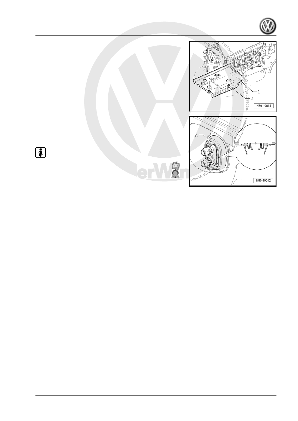
Removing heater unit baffle plate
– Remove plastic bolts -2- and remove baffle plate -1-.
Installation position of seal between heater unit and engine com‐
partment
– First insert seal between heater unit and engine compartment
-A- in bulkhead and then attach to heat exchanger.
Note
To prevent water from entering vehicle interior, installation posi‐
tion must be observed.
Heating, air conditioning - Edition 04.2010
1. Repairing heating system 3
Page 10
P
r
o
t
e
c
t
e
d
b
y
c
o
p
y
r
i
g
h
t
.
C
o
p
y
i
n
g
f
o
r
p
r
i
v
a
t
e
o
r
c
o
m
m
e
r
c
i
a
l
p
u
r
p
o
s
e
s
,
i
n
p
a
r
t
o
r
i
n
w
h
o
l
e
,
i
s
n
o
t
p
e
r
m
i
t
t
e
d
u
n
l
e
s
s
a
u
t
h
o
r
i
s
e
d
b
y
V
o
l
k
s
w
a
g
e
n
A
G
.
V
o
l
k
s
w
a
g
e
n
A
G
d
o
e
s
n
o
t
g
u
a
r
a
n
t
e
e
o
r
a
c
c
e
p
t
a
n
y
l
i
a
b
i
l
i
t
y
w
i
t
h
r
e
s
p
e
c
t
t
o
t
h
e
c
o
r
r
e
c
t
n
e
s
s
o
f
i
n
f
o
r
m
a
t
i
o
n
i
n
t
h
i
s
d
o
c
u
m
e
n
t
.
C
o
p
y
r
i
g
h
t
b
y
V
o
l
k
s
w
a
g
e
n
A
G
.
Golf Variant 2007 ➤ , Golf Variant 2010 ➤ , Jetta 2005 ➤ , Jetta 2011 ➤
Heating, air conditioning - Edition 04.2010
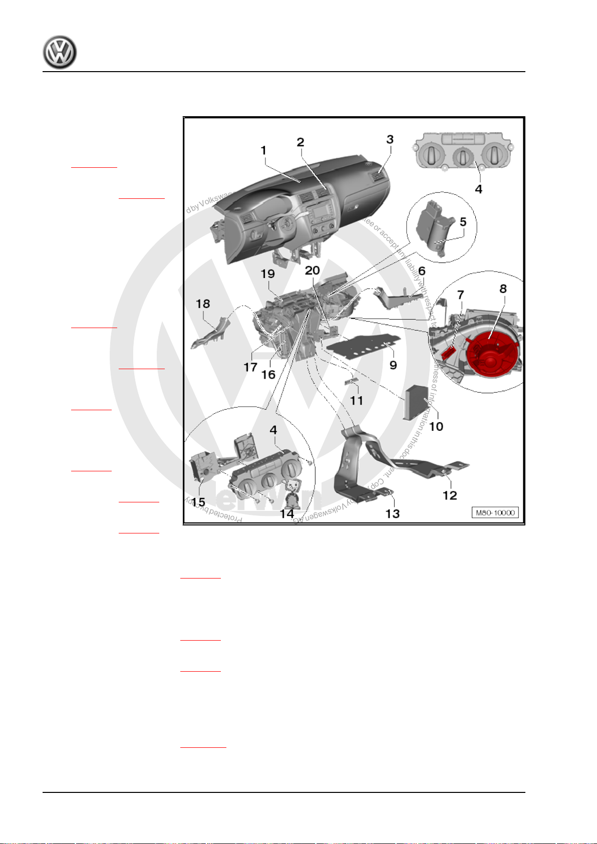
1.2 Heater - passenger compartment (Jetta 2011►)
1 - Dash panel
2 - Centre vents
❑ Removing vent
⇒ page 10 .
3 - Right side vent
❑ Removing ⇒ page 12
4 - Controls for fresh and heat‐
ed air
❑ With fresh air and air re‐
circulation flap switch -
E159- .
❑ For vehicles with sup‐
plementary heating hav‐
ing instant heating but‐
ton -E537- .
❑ Removing controls
⇒ page 14 .
5 - Fresh air and air recircula‐
tion flap control motor -V154-
❑ Removing ⇒ page 19
6 - Right footwell vent
❑ Removing and installing
⇒ page 9
7 - Fresh air blower series re‐
sistor with overheating fuse N24-
❑ Removing and installing
⇒ page 6
8 - Fresh air blower -V2-
❑ Removing ⇒ page 5
9 - Baffle plate for heater unit
❑ Removing ⇒ page 5
10 - Dust and pollen filter
❑ With activated charcoal filter
❑ Removing and installing ⇒ page 6
11 - Sealing cap
❑ Fitted only in vehicles without air duct to vent in rear centre console.
12 - Air duct for right rear footwell
❑ Removing and installing ⇒ page 8
13 - Air duct for left rear footwell
❑ Removing and installing ⇒ page 8
14 - Securing bolt
❑ Qty. 8
❑ Various lengths.
15 - Adapter for controls
❑ Removing and installing ⇒ page 18
16 - Heat exchanger
❑ After renewing heat exchanger, renew coolant completely ⇒ Rep. gr. 19 .
4 Rep. gr.80 - Heating
Page 11
P
r
o
t
e
c
t
e
d
b
y
c
o
p
y
r
i
g
h
t
.
C
o
p
y
i
n
g
f
o
r
p
r
i
v
a
t
e
o
r
c
o
m
m
e
r
c
i
a
l
p
u
r
p
o
s
e
s
,
i
n
p
a
r
t
o
r
i
n
w
h
o
l
e
,
i
s
n
o
t
p
e
r
m
i
t
t
e
d
u
n
l
e
s
s
a
u
t
h
o
r
i
s
e
d
b
y
V
o
l
k
s
w
a
g
e
n
A
G
.
V
o
l
k
s
w
a
g
e
n
A
G
d
o
e
s
n
o
t
g
u
a
r
a
n
t
e
e
o
r
a
c
c
e
p
t
a
n
y
l
i
a
b
i
l
i
t
y
w
i
t
h
r
e
s
p
e
c
t
t
o
t
h
e
c
o
r
r
e
c
t
n
e
s
s
o
f
i
n
f
o
r
m
a
t
i
o
n
i
n
t
h
i
s
d
o
c
u
m
e
n
t
.
C
o
p
y
r
i
g
h
t
b
y
V
o
l
k
s
w
a
g
e
n
A
G
.
Golf Variant 2007 ➤ , Golf Variant 2010 ➤ , Jetta 2005 ➤ , Jetta 2011 ➤
Heating, air conditioning - Edition 04.2010
❑ Removing and installing ⇒ page 23
17 - Bowden cable for temperature flap
❑ Removing and installing ⇒ page 18
18 - Left footwell vent
❑ Removing and installing ⇒ page 9
19 - Heater unit
❑ Removing and installing ⇒ page 31
❑ Dismantling and assembling ⇒ page 35
20 - Flexible shaft
❑ Removing and installing ⇒ page 17
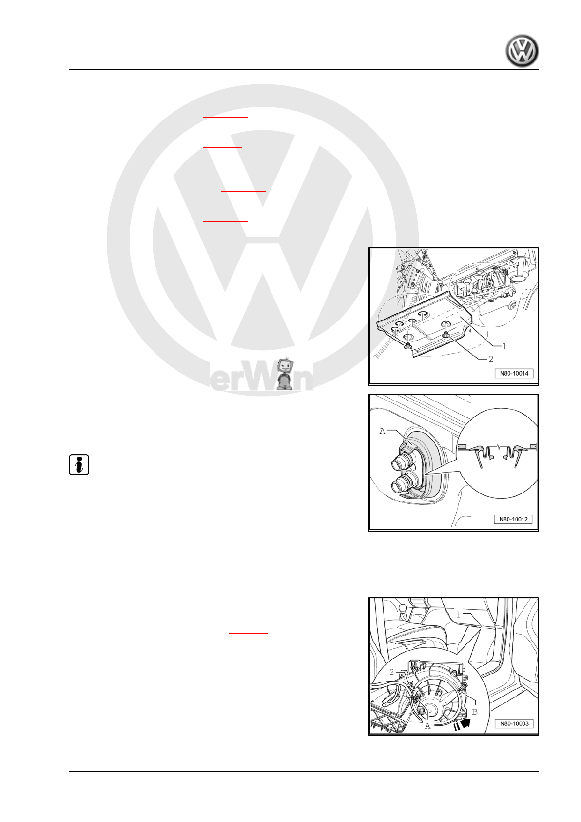
Removing heater unit baffle plate
– Remove plastic bolts -2- and remove baffle plate -1-.
Installation position of seal between heater unit and engine com‐
partment
– First insert seal between heater unit and engine compartment
-A- in bulkhead and then attach to heat exchanger.
Note
To prevent water from entering vehicle interior, installation posi‐
tion must be observed.
1.3 Removing fresh air blower -V2-
1.3.1 Removing
Fresh air blower -V2- is accessible from footwell on front passen‐
ger side.
– Removing heater unit baffle plate ⇒ page 3 .
– Pull connector -A- off fresh air blower -V2- .
– Remove bolt -B- for fresh air blower -V2- (1 Nm).
– Release catch -2-, turn fresh air blower -V2- in direction of
-arrow- and remove.
1. Repairing heating system 5
Page 12
P
r
o
t
e
c
t
e
d
b
y
c
o
p
y
r
i
g
h
t
.
C
o
p
y
i
n
g
f
o
r
p
r
i
v
a
t
e
o
r
c
o
m
m
e
r
c
i
a
l
p
u
r
p
o
s
e
s
,
i
n
p
a
r
t
o
r
i
n
w
h
o
l
e
,
i
s
n
o
t
p
e
r
m
i
t
t
e
d
u
n
l
e
s
s
a
u
t
h
o
r
i
s
e
d
b
y
V
o
l
k
s
w
a
g
e
n
A
G
.
V
o
l
k
s
w
a
g
e
n
A
G
d
o
e
s
n
o
t
g
u
a
r
a
n
t
e
e
o
r
a
c
c
e
p
t
a
n
y
l
i
a
b
i
l
i
t
y
w
i
t
h
r
e
s
p
e
c
t
t
o
t
h
e
c
o
r
r
e
c
t
n
e
s
s
o
f
i
n
f
o
r
m
a
t
i
o
n
i
n
t
h
i
s
d
o
c
u
m
e
n
t
.
C
o
p
y
r
i
g
h
t
b
y
V
o
l
k
s
w
a
g
e
n
A
G
.
Golf Variant 2007 ➤ , Golf Variant 2010 ➤ , Jetta 2005 ➤ , Jetta 2011 ➤
Heating, air conditioning - Edition 04.2010
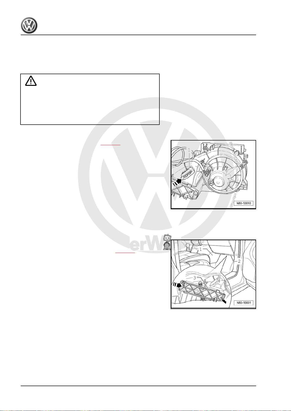
1.4 Removing and installing fresh air blower
series resistor with overheating fuse N24-
Removing
WARNING
Danger of burn injuries.
The fresh air blower series resistor with overheating fuse -N24can be hot.
Before removing fresh air blower series resistor with overheat‐
ing fuse -N24- , let it cool off.
First carry out the following work:
– Removing heater unit baffle plate ⇒ page 3 .
– Pull connector -1- off fresh air blower series resistor with over‐
heating fuse -N24- .
– Press catch in direction of -arrow- and remove fresh air blower
series resistor with overheating fuse -N24- from heater unit.
Installing
Install in reverse order.
1.5 Removing and installing dust and pollen filter
Removing
– Remove footwell cover -1- on front passenger side.
– Remove baffle plate -2- from heater unit ⇒ page 3 .
– Release cover -3- in direction of arrow.
– Remove dust and pollen filter from heater unit downwards.
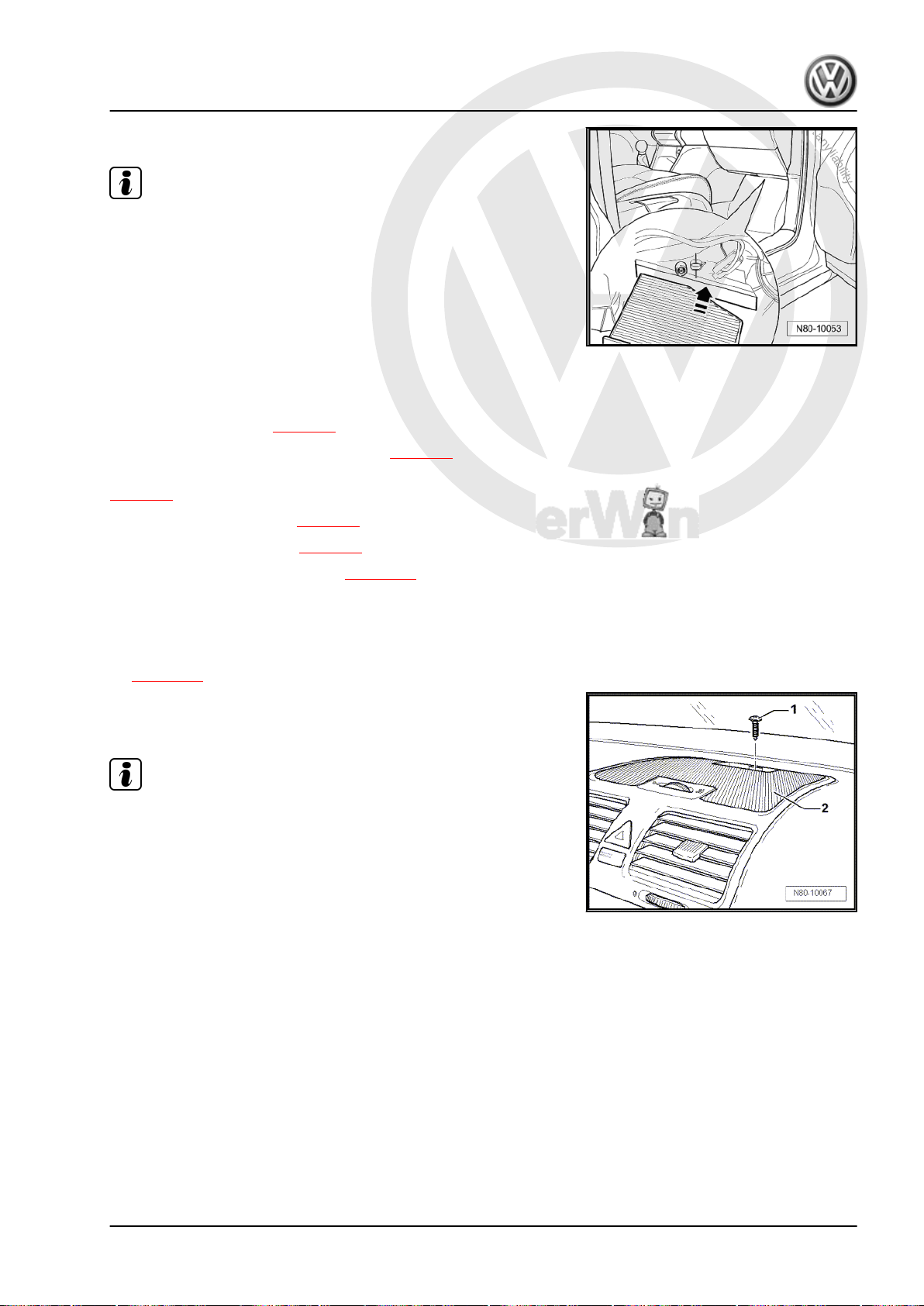
Installing
6 Rep. gr.80 - Heating
Page 13
P
r
o
t
e
c
t
e
d
b
y
c
o
p
y
r
i
g
h
t
.
C
o
p
y
i
n
g
f
o
r
p
r
i
v
a
t
e
o
r
c
o
m
m
e
r
c
i
a
l
p
u
r
p
o
s
e
s
,
i
n
p
a
r
t
o
r
i
n
w
h
o
l
e
,
i
s
n
o
t
p
e
r
m
i
t
t
e
d
u
n
l
e
s
s
a
u
t
h
o
r
i
s
e
d
b
y
V
o
l
k
s
w
a
g
e
n
A
G
.
V
o
l
k
s
w
a
g
e
n
A
G
d
o
e
s
n
o
t
g
u
a
r
a
n
t
e
e
o
r
a
c
c
e
p
t
a
n
y
l
i
a
b
i
l
i
t
y
w
i
t
h
r
e
s
p
e
c
t
t
o
t
h
e
c
o
r
r
e
c
t
n
e
s
s
o
f
i
n
f
o
r
m
a
t
i
o
n
i
n
t
h
i
s
d
o
c
u
m
e
n
t
.
C
o
p
y
r
i
g
h
t
b
y
V
o
l
k
s
w
a
g
e
n
A
G
.
Golf Variant 2007 ➤ , Golf Variant 2010 ➤ , Jetta 2005 ➤ , Jetta 2011 ➤
Install in reverse order.
Note
Observe installation position of dust and pollen filter.
1.6 Removing vent (Golf Variant 2007►, Golf Variant 2010► und Jetta 2005►)
Removing centre vents ⇒ page 7 .
Removing and installing left or right vent ⇒ page 8 .
Removing and installing right and left rear footwell air ducts
⇒ page 8 .
Remove right footwell vent ⇒ page 9 .
Removing left footwell vent ⇒ page 9 .
Removing and installing side vent ⇒ page 10 .
1.6.1 Removing and installing centre vent
Heating, air conditioning - Edition 04.2010
Removing
– Vehicles with Climatronic, photosensor must be removed
⇒ page 78 .
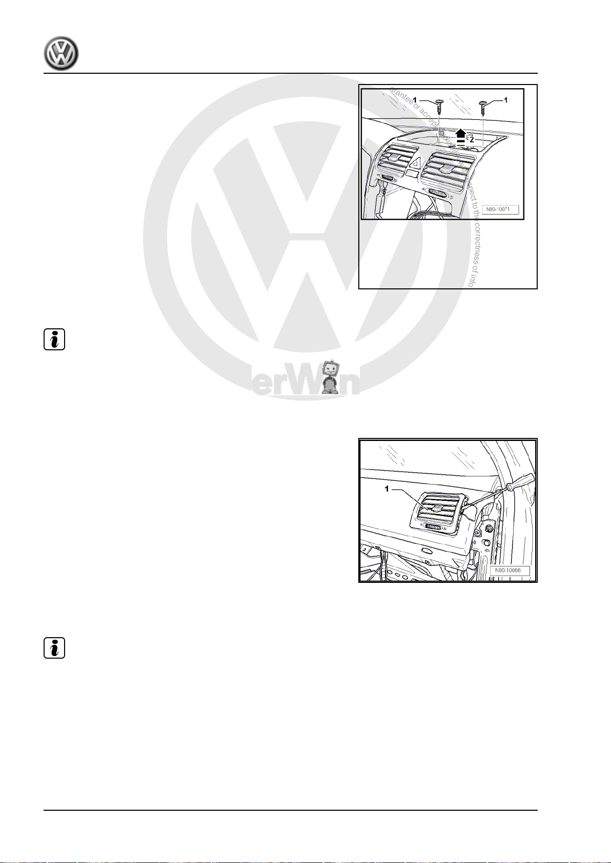
– Remove bolt -1-.
– Remove cover -2- (models with Climatronic only).
Note
For vehicles without Climatronic, bolts are beneath a trim mat.
1. Repairing heating system 7
Page 14
P
r
o
t
e
c
t
e
d
b
y
c
o
p
y
r
i
g
h
t
.
C
o
p
y
i
n
g
f
o
r
p
r
i
v
a
t
e
o
r
c
o
m
m
e
r
c
i
a
l
p
u
r
p
o
s
e
s
,
i
n
p
a
r
t
o
r
i
n
w
h
o
l
e
,
i
s
n
o
t
p
e
r
m
i
t
t
e
d
u
n
l
e
s
s
a
u
t
h
o
r
i
s
e
d
b
y
V
o
l
k
s
w
a
g
e
n
A
G
.
V
o
l
k
s
w
a
g
e
n
A
G
d
o
e
s
n
o
t
g
u
a
r
a
n
t
e
e
o
r
a
c
c
e
p
t
a
n
y
l
i
a
b
i
l
i
t
y
w
i
t
h
r
e
s
p
e
c
t
t
o
t
h
e
c
o
r
r
e
c
t
n
e
s
s
o
f
i
n
f
o
r
m
a
t
i
o
n
i
n
t
h
i
s
d
o
c
u
m
e
n
t
.
C
o
p
y
r
i
g
h
t
b
y
V
o
l
k
s
w
a
g
e
n
A
G
.
Golf Variant 2007 ➤ , Golf Variant 2010 ➤ , Jetta 2005 ➤ , Jetta 2011 ➤
Heating, air conditioning - Edition 04.2010
– Remove securing bolts -1-.
– Remove compartment from dash panel.
– Remove centre vent -2- upwards in direction of -arrow-.
– Disconnect connectors on centre vents.
Installing
Install in reverse order.
1.6.2 Removing and installing right or left vent
Note
♦
Removal of vents on both sides is identical, but one is a mirror
image of the other.
♦
To avoid damage to dash panel, use a pad when levering out
components.
Removing
– Using an appropriate tool, lever out vent -1-.
– Disconnect connector on vent.
Installing
Install in reverse order.
1.6.3 Removing and installing right and left rear footwell air ducts
Note
Removal of air ducts on both sides is identical, but one is a mirror
image of the other.
Removing
– Remove driver or front passenger seat ⇒ Rep. gr. 72 .
8 Rep. gr.80 - Heating
Page 15
P
r
o
t
e
c
t
e
d
b
y
c
o
p
y
r
i
g
h
t
.
C
o
p
y
i
n
g
f
o
r
p
r
i
v
a
t
e
o
r
c
o
m
m
e
r
c
i
a
l
p
u
r
p
o
s
e
s
,
i
n
p
a
r
t
o
r
i
n
w
h
o
l
e
,
i
s
n
o
t
p
e
r
m
i
t
t
e
d
u
n
l
e
s
s
a
u
t
h
o
r
i
s
e
d
b
y
V
o
l
k
s
w
a
g
e
n
A
G
.
V
o
l
k
s
w
a
g
e
n
A
G
d
o
e
s
n
o
t
g
u
a
r
a
n
t
e
e
o
r
a
c
c
e
p
t
a
n
y
l
i
a
b
i
l
i
t
y
w
i
t
h
r
e
s
p
e
c
t
t
o
t
h
e
c
o
r
r
e
c
t
n
e
s
s
o
f
i
n
f
o
r
m
a
t
i
o
n
i
n
t
h
i
s
d
o
c
u
m
e
n
t
.
C
o
p
y
r
i
g
h
t
b
y
V
o
l
k
s
w
a
g
e
n
A
G
.
Golf Variant 2007 ➤ , Golf Variant 2010 ➤ , Jetta 2005 ➤ , Jetta 2011 ➤
Heating, air conditioning - Edition 04.2010
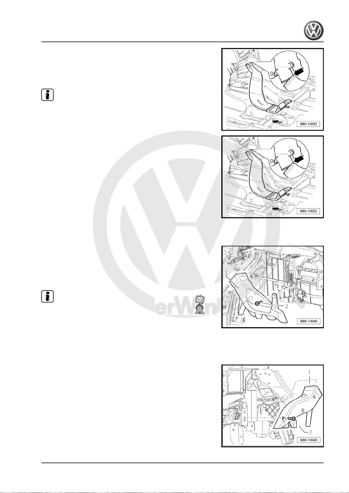
– Remove centre console ⇒ Rep. gr. 68 .
– Raise floor covering, unclip rear footwell air duct from under‐
body and pull off heater unit.
Installing
Note
When installing rear footwell air duct, ensure that it is first pushed
onto heater unit -arrow- and then clipped to underbody.
Install in reverse order.
1.6.4 Removing right footwell vent
Removing
– Remove glove compartment ⇒ Rep. gr. 68 .
– Remove securing bolt -2- and remove right footwell vent -1-.
Installing
Install in reverse order.
Note
If vehicle has glove compartment cooling, ensure that cooling
hose is properly seated.
1.6.5 Removing and installing left footwell vent
Removing
– Remove compartment on driver passenger side ⇒ Rep. gr.
68 .
– Remove securing bolt -2- and remove left footwell vent -1-.
Installing
Install in reverse order.
1. Repairing heating system 9
Page 16
P
r
o
t
e
c
t
e
d
b
y
c
o
p
y
r
i
g
h
t
.
C
o
p
y
i
n
g
f
o
r
p
r
i
v
a
t
e
o
r
c
o
m
m
e
r
c
i
a
l
p
u
r
p
o
s
e
s
,
i
n
p
a
r
t
o
r
i
n
w
h
o
l
e
,
i
s
n
o
t
p
e
r
m
i
t
t
e
d
u
n
l
e
s
s
a
u
t
h
o
r
i
s
e
d
b
y
V
o
l
k
s
w
a
g
e
n
A
G
.
V
o
l
k
s
w
a
g
e
n
A
G
d
o
e
s
n
o
t
g
u
a
r
a
n
t
e
e
o
r
a
c
c
e
p
t
a
n
y
l
i
a
b
i
l
i
t
y
w
i
t
h
r
e
s
p
e
c
t
t
o
t
h
e
c
o
r
r
e
c
t
n
e
s
s
o
f
i
n
f
o
r
m
a
t
i
o
n
i
n
t
h
i
s
d
o
c
u
m
e
n
t
.
C
o
p
y
r
i
g
h
t
b
y
V
o
l
k
s
w
a
g
e
n
A
G
.
Golf Variant 2007 ➤ , Golf Variant 2010 ➤ , Jetta 2005 ➤ , Jetta 2011 ➤
Heating, air conditioning - Edition 04.2010
1.6.6 Removing and installing side vents
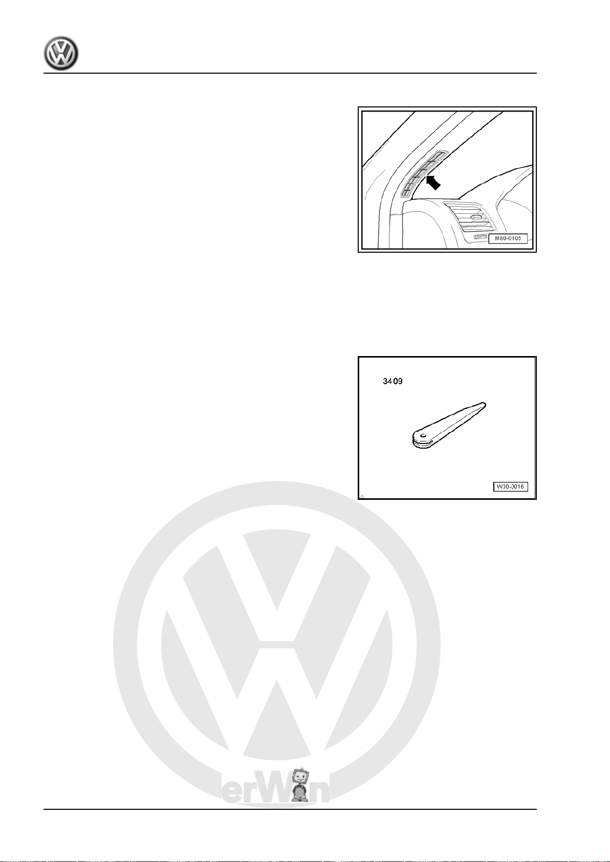
Side window vents -arrow- are installed in A-pillar trim.
– Remove left or right A-pillar trim, as appropriate ⇒ Rep. gr.
70 .
1.7 Removing vent (Jetta 2011►)
1.7.1 Removing and installing centre vent
Removing
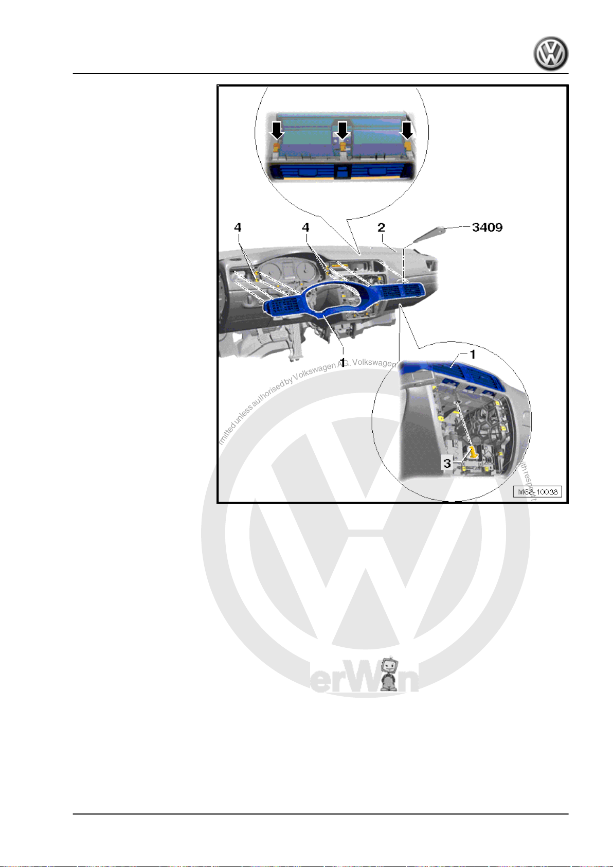
Special tools and workshop equipment required
♦ Removal wedge -3409-
– Switch off ignition.
– Remove centre trim of dash panel ⇒ General body repairs,
interior; Rep. gr. 68 ; Removing and installing centre trim of
dash panel .
– Remove Radio, if fitted ⇒ Communication; Rep. gr. 91 ; Re‐
moving and installing radio units and navigation systems .
Vehicles with radio navigation systems
– Remove radio navigation system ⇒ Communication; Rep. gr.
91 ; Removing and installing radio units and navigation sys‐
tems .
For all vehicles
– Height adjustment: move steering wheel to lowest position.
10 Rep. gr.80 - Heating
Page 17
P
r
o
t
e
c
t
e
d
b
y
c
o
p
y
r
i
g
h
t
.
C
o
p
y
i
n
g
f
o
r
p
r
i
v
a
t
e
o
r
c
o
m
m
e
r
c
i
a
l
p
u
r
p
o
s
e
s
,
i
n
p
a
r
t
o
r
i
n
w
h
o
l
e
,
i
s
n
o
t
p
e
r
m
i
t
t
e
d
u
n
l
e
s
s
a
u
t
h
o
r
i
s
e
d
b
y
V
o
l
k
s
w
a
g
e
n
A
G
.
V
o
l
k
s
w
a
g
e
n
A
G
d
o
e
s
n
o
t
g
u
a
r
a
n
t
e
e
o
r
a
c
c
e
p
t
a
n
y
l
i
a
b
i
l
i
t
y
w
i
t
h
r
e
s
p
e
c
t
t
o
t
h
e
c
o
r
r
e
c
t
n
e
s
s
o
f
i
n
f
o
r
m
a
t
i
o
n
i
n
t
h
i
s
d
o
c
u
m
e
n
t
.
C
o
p
y
r
i
g
h
t
b
y
V
o
l
k
s
w
a
g
e
n
A
G
.
Golf Variant 2007 ➤ , Golf Variant 2010 ➤ , Jetta 2005 ➤ , Jetta 2011 ➤
Heating, air conditioning - Edition 04.2010
– Reach adjustment: move steering wheel so that the steering
wheel is as far into the passenger compartment as possible.
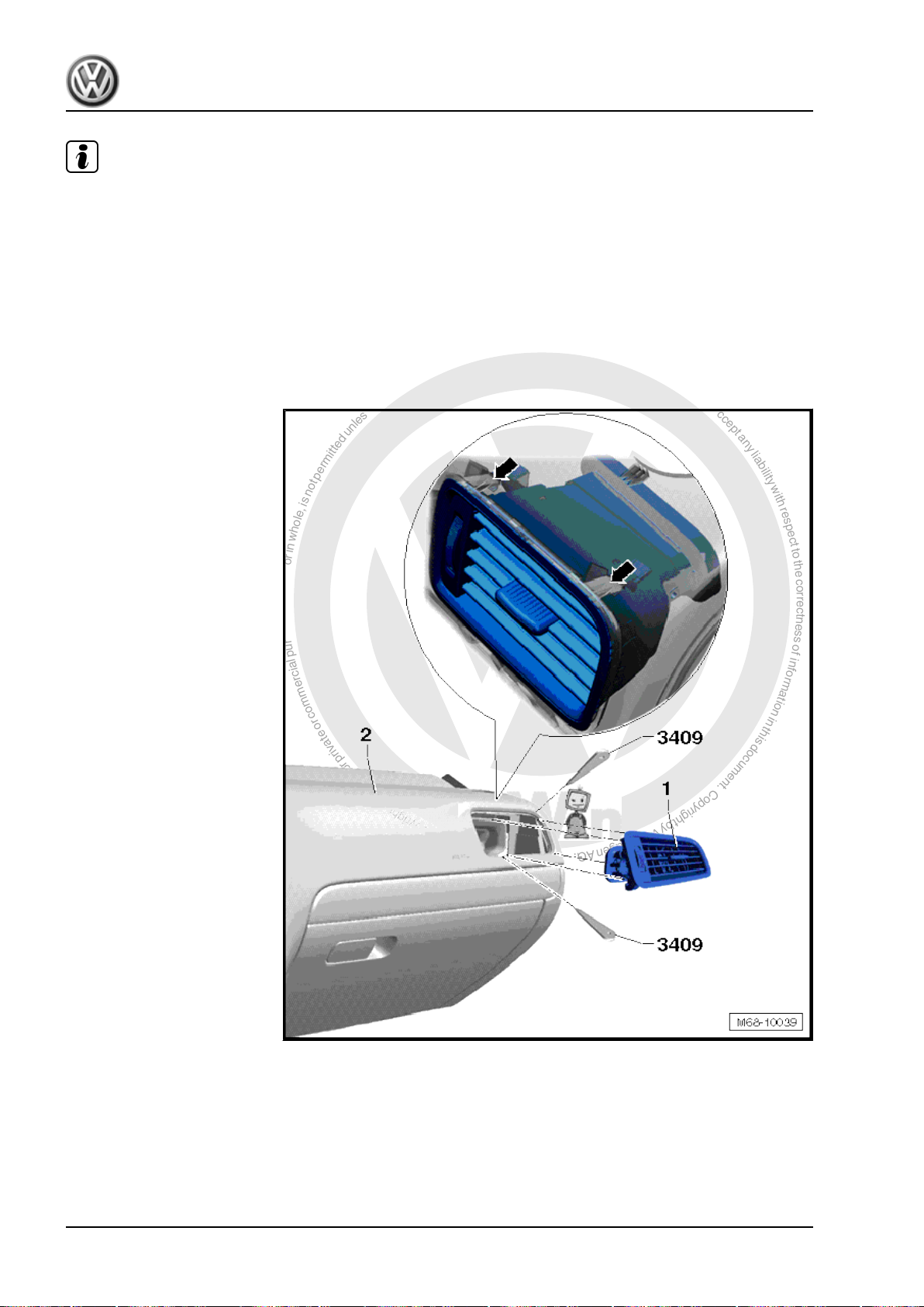
– Release gap cover from mounting in upper part of trim with
wedge -3409- . The complete steering column trim must not
be removed.
– Remove bolt -3- (1.5 Nm).
– Release clips of centre vent -arrows- using wedge -3409- and
pull out dash panel insert trim with centre vent -1- slightly.
– Release clips of left vent using wedge -3409- and pull out dash
panel insert trim with centre vent -1- slightly.
– Release fasteners -4- of dash panel insert trim -1- using wedge
-3409- and pull out slightly.
– Remove dash panel insert trim with centre and left vents -1-
from dash panel -2-, disconnect wiring harness to hazard
warning light switch -E3- when doing this.
Installing
Install in reverse order.
1. Repairing heating system 11
Page 18
P
r
o
t
e
c
t
e
d
b
y
c
o
p
y
r
i
g
h
t
.
C
o
p
y
i
n
g
f
o
r
p
r
i
v
a
t
e
o
r
c
o
m
m
e
r
c
i
a
l
p
u
r
p
o
s
e
s
,
i
n
p
a
r
t
o
r
i
n
w
h
o
l
e
,
i
s
n
o
t
p
e
r
m
i
t
t
e
d
u
n
l
e
s
s
a
u
t
h
o
r
i
s
e
d
b
y
V
o
l
k
s
w
a
g
e
n
A
G
.
V
o
l
k
s
w
a
g
e
n
A
G
d
o
e
s
n
o
t
g
u
a
r
a
n
t
e
e
o
r
a
c
c
e
p
t
a
n
y
l
i
a
b
i
l
i
t
y
w
i
t
h
r
e
s
p
e
c
t
t
o
t
h
e
c
o
r
r
e
c
t
n
e
s
s
o
f
i
n
f
o
r
m
a
t
i
o
n
i
n
t
h
i
s
d
o
c
u
m
e
n
t
.
C
o
p
y
r
i
g
h
t
b
y
V
o
l
k
s
w
a
g
e
n
A
G
.
Golf Variant 2007 ➤ , Golf Variant 2010 ➤ , Jetta 2005 ➤ , Jetta 2011 ➤
Heating, air conditioning - Edition 04.2010
Note
Before installing, check all securing elements for damage and re‐
place as necessary.
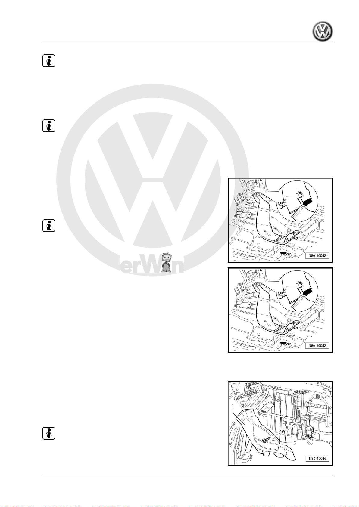
1.7.2 Removing and installing right dash pan‐
el vent
Removing
– Release upper and lower clips -arrows- of right vent using
wedge -3409- and pull vent out slightly.
– Remove right dash panel vent -1- from dash panel -2-.
Installing
– Installation is carried out in reverse order.
12 Rep. gr.80 - Heating
Page 19
P
r
o
t
e
c
t
e
d
b
y
c
o
p
y
r
i
g
h
t
.
C
o
p
y
i
n
g
f
o
r
p
r
i
v
a
t
e
o
r
c
o
m
m
e
r
c
i
a
l
p
u
r
p
o
s
e
s
,
i
n
p
a
r
t
o
r
i
n
w
h
o
l
e
,
i
s
n
o
t
p
e
r
m
i
t
t
e
d
u
n
l
e
s
s
a
u
t
h
o
r
i
s
e
d
b
y
V
o
l
k
s
w
a
g
e
n
A
G
.
V
o
l
k
s
w
a
g
e
n
A
G
d
o
e
s
n
o
t
g
u
a
r
a
n
t
e
e
o
r
a
c
c
e
p
t
a
n
y
l
i
a
b
i
l
i
t
y
w
i
t
h
r
e
s
p
e
c
t
t
o
t
h
e
c
o
r
r
e
c
t
n
e
s
s
o
f
i
n
f
o
r
m
a
t
i
o
n
i
n
t
h
i
s
d
o
c
u
m
e
n
t
.
C
o
p
y
r
i
g
h
t
b
y
V
o
l
k
s
w
a
g
e
n
A
G
.
Note
Golf Variant 2007 ➤ , Golf Variant 2010 ➤ , Jetta 2005 ➤ , Jetta 2011 ➤
Heating, air conditioning - Edition 04.2010
Before installing, check all securing elements for damage and re‐
place as necessary.
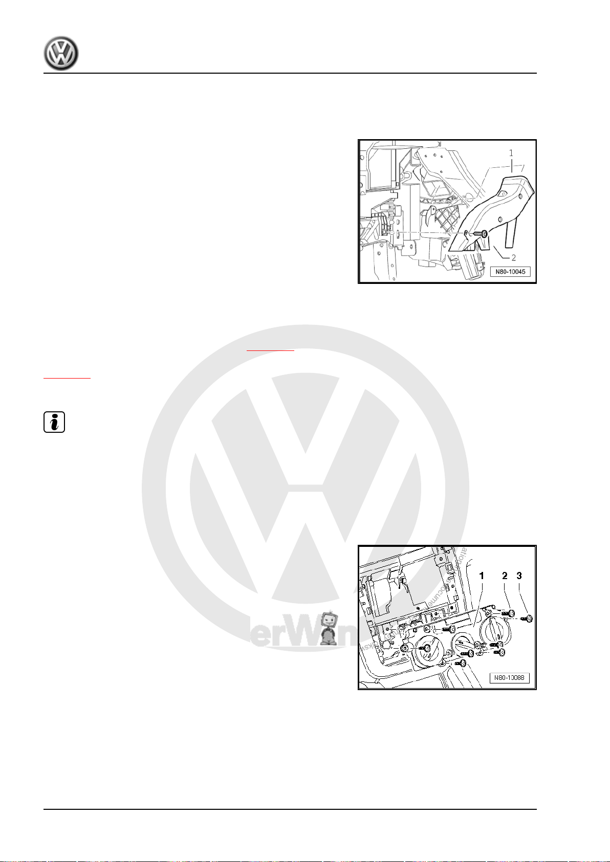
1.7.3 Removing and installing right and left rear footwell air ducts
Note
Removal of air ducts on both sides is identical, but one is a mirror
image of the other.
Removing
– Remove driver or front passenger seat ⇒ Rep. gr. 72 .
– Remove centre console ⇒ Rep. gr. 68 .
– Raise floor covering, unclip rear footwell air duct from under‐
Installing
When installing rear footwell air duct, ensure that it is first pushed
onto heater unit -arrow- and then clipped to underbody.
Install in reverse order.
body and pull off heater unit.
Note
1.7.4 Removing right footwell vent
Removing
– Remove glove compartment ⇒ Rep. gr. 68 .
– Remove securing bolt -2- and remove right footwell vent -1-.
Installing
Install in reverse order.
Note
If vehicle has glove compartment cooling, ensure that cooling
hose is properly seated.
1. Repairing heating system 13
Page 20
P
r
o
t
e
c
t
e
d
b
y
c
o
p
y
r
i
g
h
t
.
C
o
p
y
i
n
g
f
o
r
p
r
i
v
a
t
e
o
r
c
o
m
m
e
r
c
i
a
l
p
u
r
p
o
s
e
s
,
i
n
p
a
r
t
o
r
i
n
w
h
o
l
e
,
i
s
n
o
t
p
e
r
m
i
t
t
e
d
u
n
l
e
s
s
a
u
t
h
o
r
i
s
e
d
b
y
V
o
l
k
s
w
a
g
e
n
A
G
.
V
o
l
k
s
w
a
g
e
n
A
G
d
o
e
s
n
o
t
g
u
a
r
a
n
t
e
e
o
r
a
c
c
e
p
t
a
n
y
l
i
a
b
i
l
i
t
y
w
i
t
h
r
e
s
p
e
c
t
t
o
t
h
e
c
o
r
r
e
c
t
n
e
s
s
o
f
i
n
f
o
r
m
a
t
i
o
n
i
n
t
h
i
s
d
o
c
u
m
e
n
t
.
C
o
p
y
r
i
g
h
t
b
y
V
o
l
k
s
w
a
g
e
n
A
G
.
Golf Variant 2007 ➤ , Golf Variant 2010 ➤ , Jetta 2005 ➤ , Jetta 2011 ➤
Heating, air conditioning - Edition 04.2010
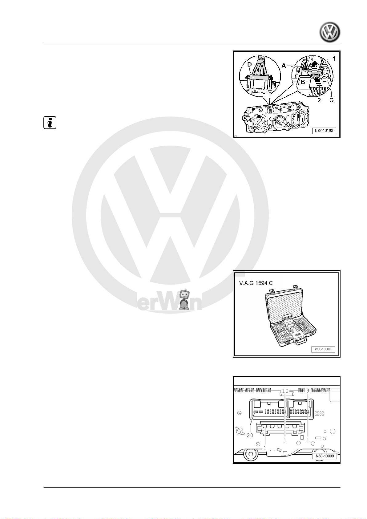
1.7.5 Removing and installing left footwell vent
Removing
– Remove compartment on driver passenger side ⇒ Rep. gr.
68 .
– Remove securing bolt -2- and remove left footwell vent -1-.
Installing
Install in reverse order.
1.8 Removing and installing controls for heated and fresh air
Connectors on controls for heated and fresh air (Golf Variant
2007►, Golf Variant 2010► und Jetta 2005►) ⇒ page 15
Connectors on controls for heated and fresh air (Jetta 2011►)
⇒ page 16
Removing
Note
♦
The control consists of 2 separable housings. Before removing
controls, set rotary knobs to the following positions:
♦
Heater control to „cold“
♦
Blower to „0“
♦
Vent direction to „footwell“
– Remove radio ⇒ Rep. gr. 91 .
– Models with no radio trim, removing centre part of dash panel
⇒ Rep. gr. 68 .
14 Rep. gr.80 - Heating
Page 21
P
r
o
t
e
c
t
e
d
b
y
c
o
p
y
r
i
g
h
t
.
C
o
p
y
i
n
g
f
o
r
p
r
i
v
a
t
e
o
r
c
o
m
m
e
r
c
i
a
l
p
u
r
p
o
s
e
s
,
i
n
p
a
r
t
o
r
i
n
w
h
o
l
e
,
i
s
n
o
t
p
e
r
m
i
t
t
e
d
u
n
l
e
s
s
a
u
t
h
o
r
i
s
e
d
b
y
V
o
l
k
s
w
a
g
e
n
A
G
.
V
o
l
k
s
w
a
g
e
n
A
G
d
o
e
s
n
o
t
g
u
a
r
a
n
t
e
e
o
r
a
c
c
e
p
t
a
n
y
l
i
a
b
i
l
i
t
y
w
i
t
h
r
e
s
p
e
c
t
t
o
t
h
e
c
o
r
r
e
c
t
n
e
s
s
o
f
i
n
f
o
r
m
a
t
i
o
n
i
n
t
h
i
s
d
o
c
u
m
e
n
t
.
C
o
p
y
r
i
g
h
t
b
y
V
o
l
k
s
w
a
g
e
n
A
G
.
Golf Variant 2007 ➤ , Golf Variant 2010 ➤ , Jetta 2005 ➤ , Jetta 2011 ➤
Heating, air conditioning - Edition 04.2010
– Remove bolts -2- (4.2 x 45) and -3- (4.2 x 16) and remove the
controls -1- from centre console.
– Release connector catch -A- by pulling it in direction of arrow
-1-.
– Push connector catch -B- towards connector -arrow 2- and
remove connector -C-.
– Release connector catch -D- and remove connector -D-.
Note
Figure shows Climatic version. The procedure for releasing con‐
nector is the same.
Installing
Install in reverse order. Note: the rotating knobs must be in the
same position as when removed.
1.9 Connectors on controls for heated and
1.9.1 Pin assignment for multi-pin connectors
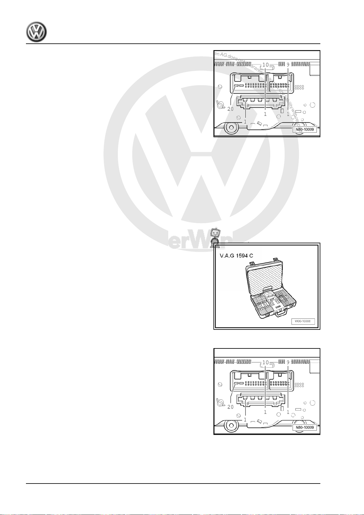
Special tools and workshop equipment required
♦ Auxiliary measuring set -V.A.G 1594 C-
fresh air (Golf Variant 2007►, Golf Var‐
iant 2010► und Jetta 2005►)
on back of controls for heated and fresh
air
16-pin connector is vacant.
5-pin connector, T5 in current flow diagram
1 - Blower 3rd speed
2 - Blower 2nd speed
3 - Blower 1st speed
4 - Bower 4th speed
5 - X terminal
1. Repairing heating system 15
Page 22
P
r
o
t
e
c
t
e
d
b
y
c
o
p
y
r
i
g
h
t
.
C
o
p
y
i
n
g
f
o
r
p
r
i
v
a
t
e
o
r
c
o
m
m
e
r
c
i
a
l
p
u
r
p
o
s
e
s
,
i
n
p
a
r
t
o
r
i
n
w
h
o
l
e
,
i
s
n
o
t
p
e
r
m
i
t
t
e
d
u
n
l
e
s
s
a
u
t
h
o
r
i
s
e
d
b
y
V
o
l
k
s
w
a
g
e
n
A
G
.
V
o
l
k
s
w
a
g
e
n
A
G
d
o
e
s
n
o
t
g
u
a
r
a
n
t
e
e
o
r
a
c
c
e
p
t
a
n
y
l
i
a
b
i
l
i
t
y
w
i
t
h
r
e
s
p
e
c
t
t
o
t
h
e
c
o
r
r
e
c
t
n
e
s
s
o
f
i
n
f
o
r
m
a
t
i
o
n
i
n
t
h
i
s
d
o
c
u
m
e
n
t
.
C
o
p
y
r
i
g
h
t
b
y
V
o
l
k
s
w
a
g
e
n
A
G
.
Golf Variant 2007 ➤ , Golf Variant 2010 ➤ , Jetta 2005 ➤ , Jetta 2011 ➤
Heating, air conditioning - Edition 04.2010
20-pin connector, T20c in current flow diagram
3 - Fresh air and air recirculation flap control motor -V154-
6 - Fresh air and air recirculation flap control motor -V154-
7 - With auxiliary air heater control unit -J604-
8 - Rear window
11 - Heated driver seat control unit -J131-
15 - Heated front passenger seat control unit -J132-
16 - Terminal 75, seat heating (optional)
18 - Terminal 30
19 - Terminal 15
20 - Terminal 31
1.10 Connectors on controls for heated and fresh air (Jetta 2011►)
1.10.1 Pin assignment for multi-pin connectors on back of controls for heated and fresh air
Special tools and workshop equipment required
♦ Auxiliary measuring set -V.A.G 1594 C-
16-pin connector is vacant.
5-pin connector, T5 in current flow diagram
1 - Blower 3rd speed
2 - Blower 2nd speed
3 - Blower 1st speed
4 - Bower 4th speed
5 - X terminal
16 Rep. gr.80 - Heating
Page 23
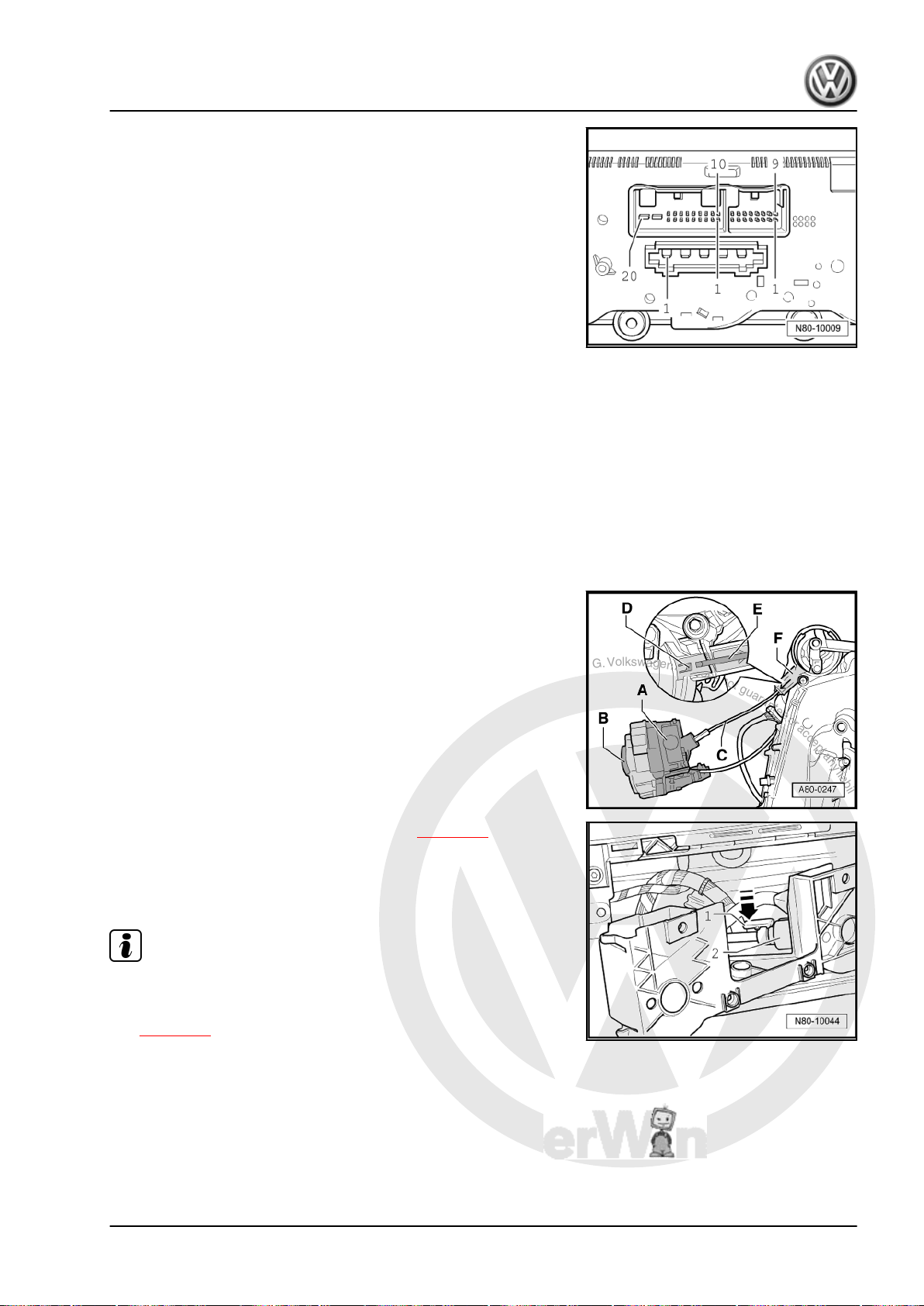
P
r
o
t
e
c
t
e
d
b
y
c
o
p
y
r
i
g
h
t
.
C
o
p
y
i
n
g
f
o
r
p
r
i
v
a
t
e
o
r
c
o
m
m
e
r
c
i
a
l
p
u
r
p
o
s
e
s
,
i
n
p
a
r
t
o
r
i
n
w
h
o
l
e
,
i
s
n
o
t
p
e
r
m
i
t
t
e
d
u
n
l
e
s
s
a
u
t
h
o
r
i
s
e
d
b
y
V
o
l
k
s
w
a
g
e
n
A
G
.
V
o
l
k
s
w
a
g
e
n
A
G
d
o
e
s
n
o
t
g
u
a
r
a
n
t
e
e
o
r
a
c
c
e
p
t
a
n
y
l
i
a
b
i
l
i
t
y
w
i
t
h
r
e
s
p
e
c
t
t
o
t
h
e
c
o
r
r
e
c
t
n
e
s
s
o
f
i
n
f
o
r
m
a
t
i
o
n
i
n
t
h
i
s
d
o
c
u
m
e
n
t
.
C
o
p
y
r
i
g
h
t
b
y
V
o
l
k
s
w
a
g
e
n
A
G
.
Golf Variant 2007 ➤ , Golf Variant 2010 ➤ , Jetta 2005 ➤ , Jetta 2011 ➤
Heating, air conditioning - Edition 04.2010
20-pin connector, T20c in current flow diagram
3 - Fresh air and air recirculation flap control motor -V154-
5 - Auxiliary heater (optional)
6 - Fresh air and air recirculation flap control motor -V154-
7 - With auxiliary air heater control unit -J604-
8 - Rear window
11 - Left seat heating (optional)
12 - LED for heated rear window
14 - LED for auxiliary heater
15 - Right seat heating (optional)
17 - Terminal 58d
18 - Terminal 30
19 - Terminal 15
20 - Terminal 31
1.11 Removing and installing flexible shaft for air distribution
Removing
– Remove glove compartment ⇒ Rep. gr. 68 .
– Move flexible shaft to following position:
– Turn rotary switch for air distribution -B- until catch in shaft
-D- is visible in gears -F-.
– Remove controls for fresh and heated air ⇒ page 14 .
– Reach into centre console and release locking lug -1- by
pressing in direction of -arrow-.
– Pull flexible shaft out of adapter -2-.
Note
When flexible shaft is installed, the adapter and the rotary knobs
of the controls for heated and fresh air must be aligned in a spe‐
cific position to one another. Otherwise the system will malfunc‐
tion ⇒ page 17 .
1.11.1 Checking
Flexible shaft for air distribution flap actuator:
– Run fresh air blower at highest speed. If air flows out of de‐
froster vent in the „defrost“ position, and no air flows out of
footwell vent, then the flexible shaft is correctly installed. Oth‐
erwise, remove flexible shaft from adapter. Position controls
for heated and fresh air on adapter and turn rotary knob for air
1. Repairing heating system 17
Page 24
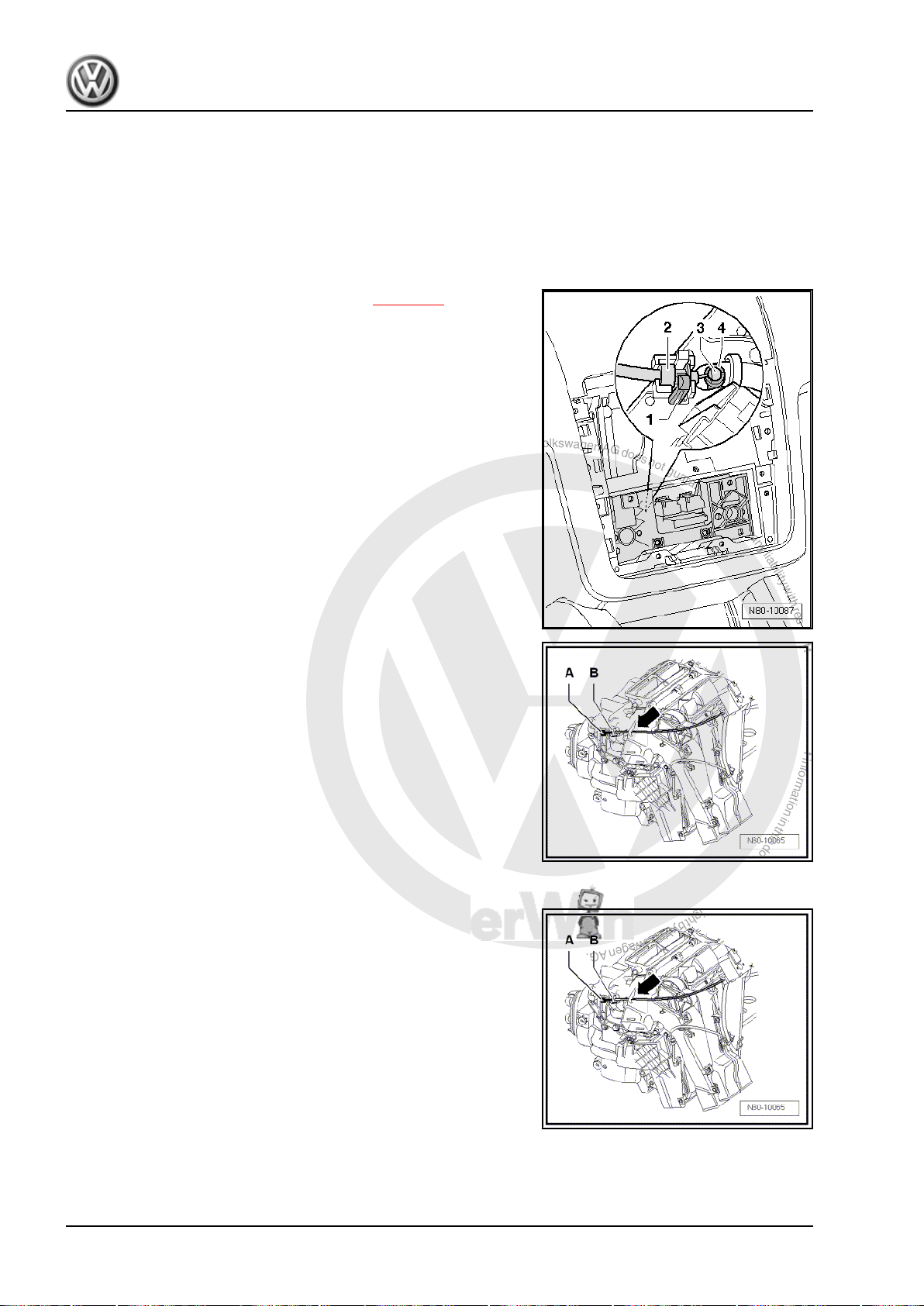
P
r
o
t
e
c
t
e
d
b
y
c
o
p
y
r
i
g
h
t
.
C
o
p
y
i
n
g
f
o
r
p
r
i
v
a
t
e
o
r
c
o
m
m
e
r
c
i
a
l
p
u
r
p
o
s
e
s
,
i
n
p
a
r
t
o
r
i
n
w
h
o
l
e
,
i
s
n
o
t
p
e
r
m
i
t
t
e
d
u
n
l
e
s
s
a
u
t
h
o
r
i
s
e
d
b
y
V
o
l
k
s
w
a
g
e
n
A
G
.
V
o
l
k
s
w
a
g
e
n
A
G
d
o
e
s
n
o
t
g
u
a
r
a
n
t
e
e
o
r
a
c
c
e
p
t
a
n
y
l
i
a
b
i
l
i
t
y
w
i
t
h
r
e
s
p
e
c
t
t
o
t
h
e
c
o
r
r
e
c
t
n
e
s
s
o
f
i
n
f
o
r
m
a
t
i
o
n
i
n
t
h
i
s
d
o
c
u
m
e
n
t
.
C
o
p
y
r
i
g
h
t
b
y
V
o
l
k
s
w
a
g
e
n
A
G
.
Golf Variant 2007 ➤ , Golf Variant 2010 ➤ , Jetta 2005 ➤ , Jetta 2011 ➤
Heating, air conditioning - Edition 04.2010
distribution 1/2 turn (180°). Then reconnect flexible shaft. Re‐
peat check.
1.12 Removing and installing Bowden cable for temperature flap
1.12.1 Removing
– Remove controls for fresh and heated air ⇒ page 14 .
– Reach into centre console and release locking lug -1- of Bow‐
den cable sleeve -2-. Take Bowden cable sleeve out of mount‐
ing.
– Release ball of Bowden cable -3- from operating lever.
– Remove driver side footwell trim ⇒ Rep. gr. 68 .
– Unclip Bowden cable from control unit for temperature flap
-A- and heater unit -B-.
1.12.2 Installing
Install in reverse order. Ensure that Bowden cable lies under hook
-arrow-.
– Check whether temperature knob can be easily turned from
„Cold“ to „Warm“.
18 Rep. gr.80 - Heating
Page 25
P
r
o
t
e
c
t
e
d
b
y
c
o
p
y
r
i
g
h
t
.
C
o
p
y
i
n
g
f
o
r
p
r
i
v
a
t
e
o
r
c
o
m
m
e
r
c
i
a
l
p
u
r
p
o
s
e
s
,
i
n
p
a
r
t
o
r
i
n
w
h
o
l
e
,
i
s
n
o
t
p
e
r
m
i
t
t
e
d
u
n
l
e
s
s
a
u
t
h
o
r
i
s
e
d
b
y
V
o
l
k
s
w
a
g
e
n
A
G
.
V
o
l
k
s
w
a
g
e
n
A
G
d
o
e
s
n
o
t
g
u
a
r
a
n
t
e
e
o
r
a
c
c
e
p
t
a
n
y
l
i
a
b
i
l
i
t
y
w
i
t
h
r
e
s
p
e
c
t
t
o
t
h
e
c
o
r
r
e
c
t
n
e
s
s
o
f
i
n
f
o
r
m
a
t
i
o
n
i
n
t
h
i
s
d
o
c
u
m
e
n
t
.
C
o
p
y
r
i
g
h
t
b
y
V
o
l
k
s
w
a
g
e
n
A
G
.
Golf Variant 2007 ➤ , Golf Variant 2010 ➤ , Jetta 2005 ➤ , Jetta 2011 ➤
Heating, air conditioning - Edition 04.2010
1.13 Removing and installing fresh air and air recirculation flap control motor -V154-
1.13.1 Removing
Note
The position of the air recirculation flap must not be changed.
– Remove glove compartment ⇒ Rep. gr. 68 .
– Remove cover -1-.
– Disconnect connector from fresh air and air recirculation flap
control motor -V154- -2-.
– Remove fresh air and air recirculation flap control motor -
V154- -2- from mounting.
1.13.2 Installing
Install in reverse order.
Note
After installing fresh air and air recirculation flap control motor V154- , check operation of air recirculation flap.
– Checking: ⇒ Vehicle diagnostic, testing and information sys‐
tem VAS 5051
– Renewing: initiate basic setting using vehicle diagnosis, test‐
ing and information system -VAS 5051B- ⇒ page 55 .
1.14 Removing and installing heat exchanger
Special tools and workshop equipment required
♦ Drip tray for workshop hoist -VAS 6208-
(Golf Variant 2007►, Golf Variant 2010►
und Jetta 2005►)
1. Repairing heating system 19
Page 26
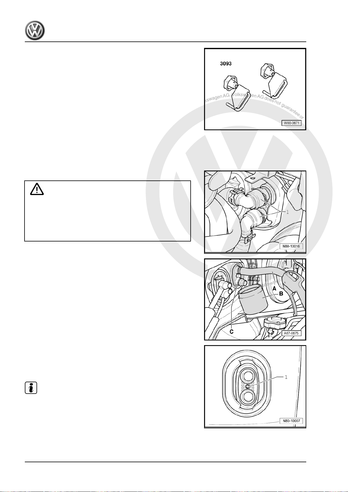
P
r
o
t
e
c
t
e
d
b
y
c
o
p
y
r
i
g
h
t
.
C
o
p
y
i
n
g
f
o
r
p
r
i
v
a
t
e
o
r
c
o
m
m
e
r
c
i
a
l
p
u
r
p
o
s
e
s
,
i
n
p
a
r
t
o
r
i
n
w
h
o
l
e
,
i
s
n
o
t
p
e
r
m
i
t
t
e
d
u
n
l
e
s
s
a
u
t
h
o
r
i
s
e
d
b
y
V
o
l
k
s
w
a
g
e
n
A
G
.
V
o
l
k
s
w
a
g
e
n
A
G
d
o
e
s
n
o
t
g
u
a
r
a
n
t
e
e
o
r
a
c
c
e
p
t
a
n
y
l
i
a
b
i
l
i
t
y
w
i
t
h
r
e
s
p
e
c
t
t
o
t
h
e
c
o
r
r
e
c
t
n
e
s
s
o
f
i
n
f
o
r
m
a
t
i
o
n
i
n
t
h
i
s
d
o
c
u
m
e
n
t
.
C
o
p
y
r
i
g
h
t
b
y
V
o
l
k
s
w
a
g
e
n
A
G
.
Golf Variant 2007 ➤ , Golf Variant 2010 ➤ , Jetta 2005 ➤ , Jetta 2011 ➤
Heating, air conditioning - Edition 04.2010
♦ Hose clamps up to 40 mm Ø -VAS 3093-
♦ Compressed air gun, commercially available
1.14.1 Removing
– Remove bulkhead in plenum chamber ⇒ Rep. gr. 50 .
– Place drip tray -VAS 6208- beneath engine.
WARNING
Danger of scalding injuries.
When the engine is warm, the coolant temperature may be
above 100 °C. The cooling system is pressurised.
If necessary, release pressure and reduce temperature before
carrying out repairs.
– Clamp off coolant hoses -1- with hose clamps up to 40 mm Ø
-VAS 3093- and disconnect coolant hoses to heat exchanger.
– Push a piece of hose -A- onto upper union of heat exchanger.
– Hold a container -B- under lower connection -C-.
– Using a compressed air pistol, carefully blow coolant out of
heat exchanger into container -B-.
– Undo bolt (6 mm hexagon socket head) -1- from union flange
between heat exchanger unions.
Note
This makes it possible to move the coolant pipes in order to re‐
move heat exchanger.
– Remove driver side footwell trim ⇒ Rep. gr. 68 .
20 Rep. gr.80 - Heating
Page 27
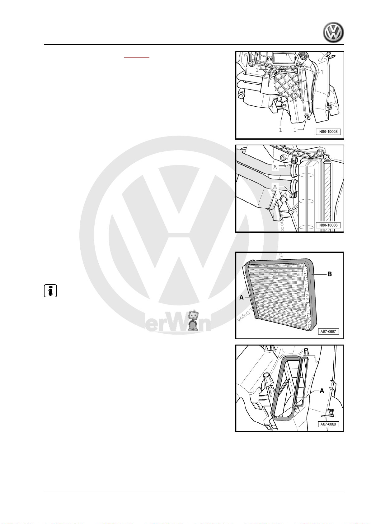
P
r
o
t
e
c
t
e
d
b
y
c
o
p
y
r
i
g
h
t
.
C
o
p
y
i
n
g
f
o
r
p
r
i
v
a
t
e
o
r
c
o
m
m
e
r
c
i
a
l
p
u
r
p
o
s
e
s
,
i
n
p
a
r
t
o
r
i
n
w
h
o
l
e
,
i
s
n
o
t
p
e
r
m
i
t
t
e
d
u
n
l
e
s
s
a
u
t
h
o
r
i
s
e
d
b
y
V
o
l
k
s
w
a
g
e
n
A
G
.
V
o
l
k
s
w
a
g
e
n
A
G
d
o
e
s
n
o
t
g
u
a
r
a
n
t
e
e
o
r
a
c
c
e
p
t
a
n
y
l
i
a
b
i
l
i
t
y
w
i
t
h
r
e
s
p
e
c
t
t
o
t
h
e
c
o
r
r
e
c
t
n
e
s
s
o
f
i
n
f
o
r
m
a
t
i
o
n
i
n
t
h
i
s
d
o
c
u
m
e
n
t
.
C
o
p
y
r
i
g
h
t
b
y
V
o
l
k
s
w
a
g
e
n
A
G
.
Golf Variant 2007 ➤ , Golf Variant 2010 ➤ , Jetta 2005 ➤ , Jetta 2011 ➤
Heating, air conditioning - Edition 04.2010
– Remove left footwell vent ⇒ page 9 .
– Remove bolts -1- and remove heat exchanger cladding.
– Cover carpet in area under heat exchanger with waterproof foil
and water absorbing paper.
– Open hose clips -A- and pull coolant pipes out of heat ex‐
changer.
– Take heat exchanger out of heater unit.
1.14.2 Installing
Install in reverse order. Note the following when doing this:
– Check seals attached to heat exchanger -A- and -B-. Install
heat exchanger only with undamaged seals.
Note
♦
An improperly bonded seal can roll up when heat exchanger
is pushed into heater unit.
♦
If seal is damaged or improperly attached, cold air can flow
past heat exchanger.
– Check heater unit for cleanliness through shaft -A- for heat
exchanger while heat exchanger is removed.
– If necessary, remove dirt or residue of leaked coolant from
heater unit, e.g. after removing a leaking heat exchanger.
– Slide heat exchanger into heater unit.
1. Repairing heating system 21
Page 28
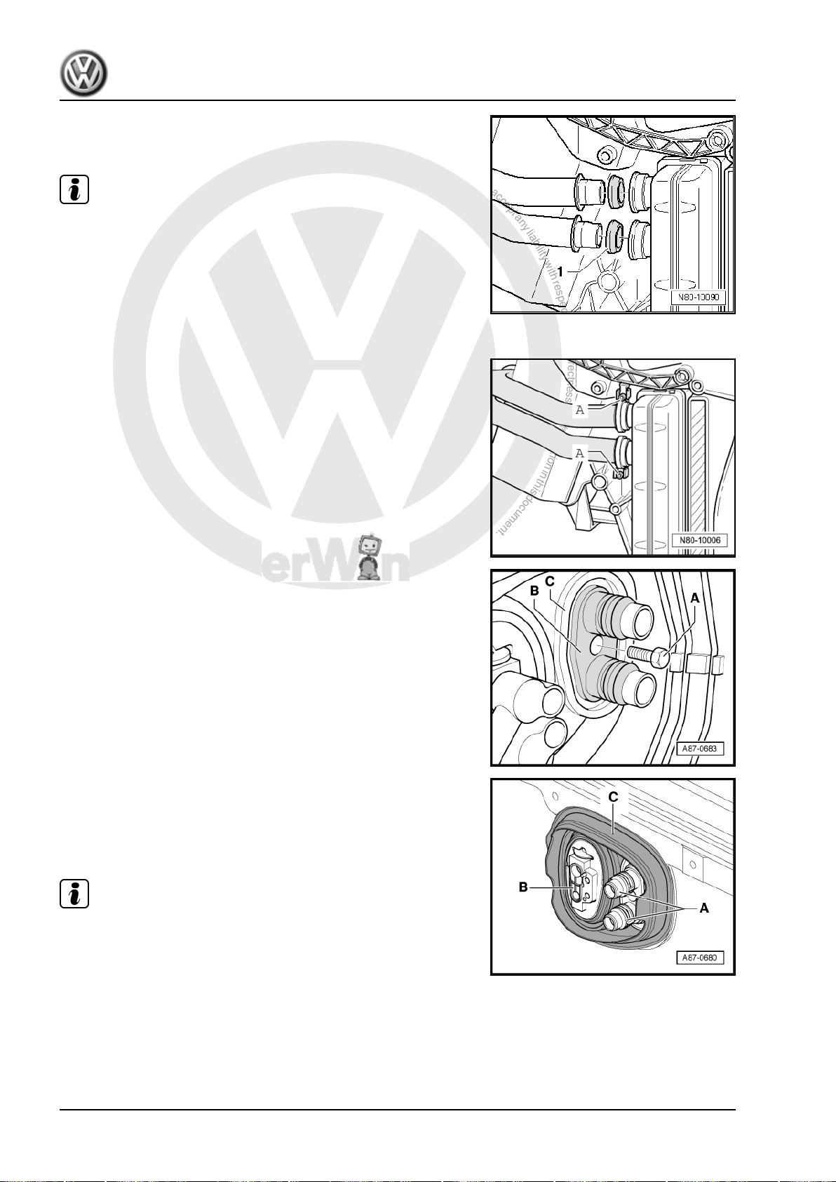
P
r
o
t
e
c
t
e
d
b
y
c
o
p
y
r
i
g
h
t
.
C
o
p
y
i
n
g
f
o
r
p
r
i
v
a
t
e
o
r
c
o
m
m
e
r
c
i
a
l
p
u
r
p
o
s
e
s
,
i
n
p
a
r
t
o
r
i
n
w
h
o
l
e
,
i
s
n
o
t
p
e
r
m
i
t
t
e
d
u
n
l
e
s
s
a
u
t
h
o
r
i
s
e
d
b
y
V
o
l
k
s
w
a
g
e
n
A
G
.
V
o
l
k
s
w
a
g
e
n
A
G
d
o
e
s
n
o
t
g
u
a
r
a
n
t
e
e
o
r
a
c
c
e
p
t
a
n
y
l
i
a
b
i
l
i
t
y
w
i
t
h
r
e
s
p
e
c
t
t
o
t
h
e
c
o
r
r
e
c
t
n
e
s
s
o
f
i
n
f
o
r
m
a
t
i
o
n
i
n
t
h
i
s
d
o
c
u
m
e
n
t
.
C
o
p
y
r
i
g
h
t
b
y
V
o
l
k
s
w
a
g
e
n
A
G
.
Golf Variant 2007 ➤ , Golf Variant 2010 ➤ , Jetta 2005 ➤ , Jetta 2011 ➤
Heating, air conditioning - Edition 04.2010
– Moisten seals -1- with coolant before installing.
– Seat seals -1- into unions on heat exchanger.
Note
♦
Ensure that seals are installed in the proper direction as shown
in figure.
♦
Renew deformed hose clips.
– Connect coolant pipes to heat exchanger.
– During assembly, hose clips -A- must turn easily on coolant
pipes.
– Hose clips -A- must be installed as shown in figure.
– Tighten hose clips -A- to 2.0 Nm.
– Check seating of both clips -A- after tightening screws. They
must fully enclose the flange on the heat exchanger and the
coolant pipe and they must not contact other components.
– Screw bolt -A- into union flange -B- ensuring that bolt actually
screws into intended securing point.
– Check grommet -C- is seating correctly in bulkhead.
– If necessary, seal flanges for coolant pipes to heat exchanger
-A- and for expansion valve (to evaporator, only vehicles with
air conditioning system) -B- at apertures in grommet -C- with
silicone adhesive sealant against water intrusion.
Note
♦
Always renew seals.
♦
Renew deformed hose clips.
♦
After renewing heat exchanger, renew coolant completely ⇒
Rep. gr. 19 .
♦
Check coolant circuit is not leaking. Pay particular attention to
unions/connections between coolant pipes and heat exchang‐
er.
22 Rep. gr.80 - Heating
Page 29
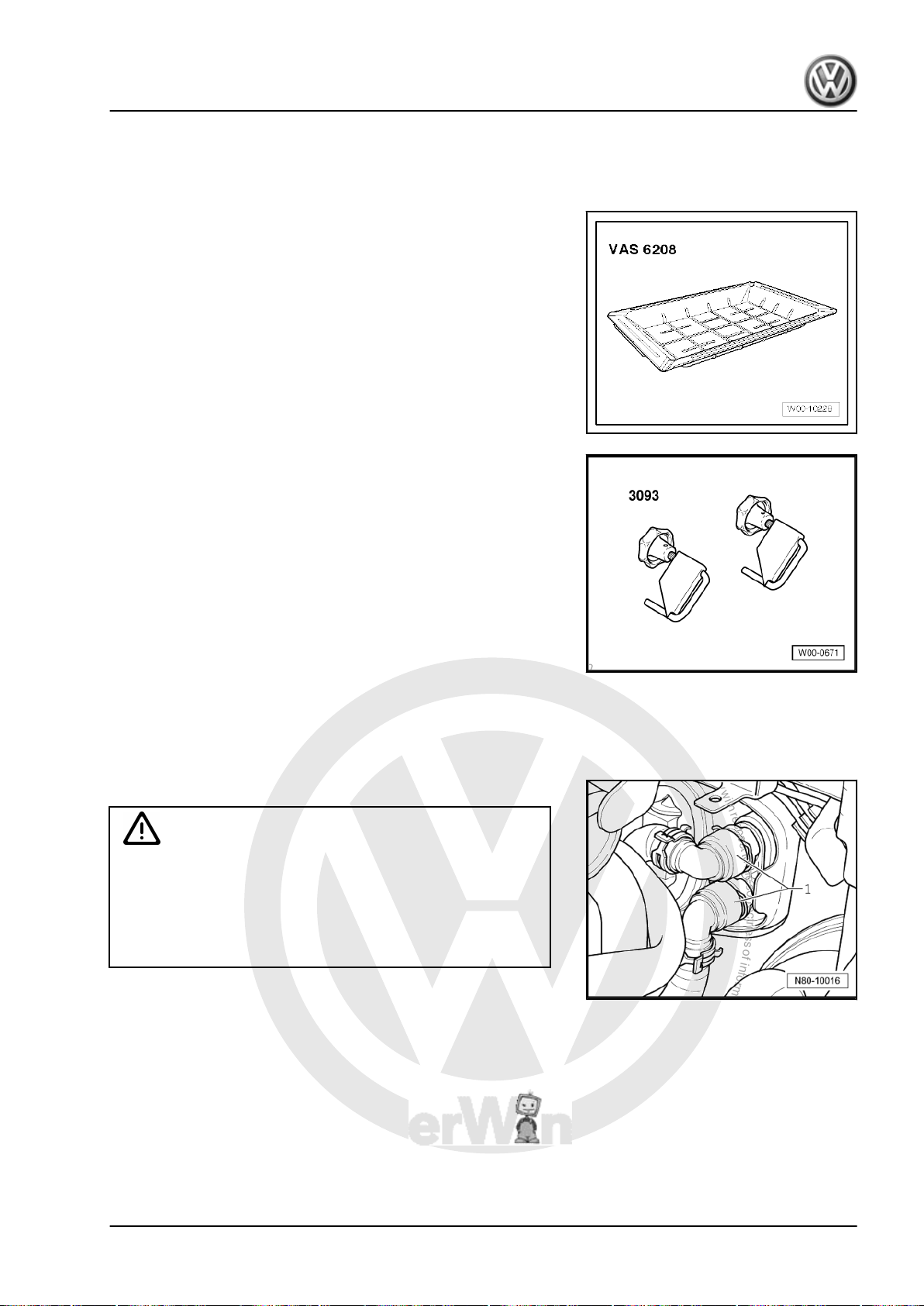
P
r
o
t
e
c
t
e
d
b
y
c
o
p
y
r
i
g
h
t
.
C
o
p
y
i
n
g
f
o
r
p
r
i
v
a
t
e
o
r
c
o
m
m
e
r
c
i
a
l
p
u
r
p
o
s
e
s
,
i
n
p
a
r
t
o
r
i
n
w
h
o
l
e
,
i
s
n
o
t
p
e
r
m
i
t
t
e
d
u
n
l
e
s
s
a
u
t
h
o
r
i
s
e
d
b
y
V
o
l
k
s
w
a
g
e
n
A
G
.
V
o
l
k
s
w
a
g
e
n
A
G
d
o
e
s
n
o
t
g
u
a
r
a
n
t
e
e
o
r
a
c
c
e
p
t
a
n
y
l
i
a
b
i
l
i
t
y
w
i
t
h
r
e
s
p
e
c
t
t
o
t
h
e
c
o
r
r
e
c
t
n
e
s
s
o
f
i
n
f
o
r
m
a
t
i
o
n
i
n
t
h
i
s
d
o
c
u
m
e
n
t
.
C
o
p
y
r
i
g
h
t
b
y
V
o
l
k
s
w
a
g
e
n
A
G
.
Golf Variant 2007 ➤ , Golf Variant 2010 ➤ , Jetta 2005 ➤ , Jetta 2011 ➤
Heating, air conditioning - Edition 04.2010
1.15 Removing and installing heat exchanger (Jetta 2010►)
Special tools and workshop equipment required
♦ Drip tray for workshop hoist -VAS 6208-
♦ Hose clamps up to 40 mm Ø -VAS 3093-
♦ Compressed air gun, commercially available
1.15.1 Removing
– Remove bulkhead in plenum chamber ⇒ Rep. gr. 50 .
– Place drip tray -VAS 6208- beneath engine.
WARNING
Danger of scalding injuries.
When the engine is warm, the coolant temperature may be
above 100 °C. The cooling system is pressurised.
If necessary, release pressure and reduce temperature before
carrying out repairs.
1. Repairing heating system 23
Page 30
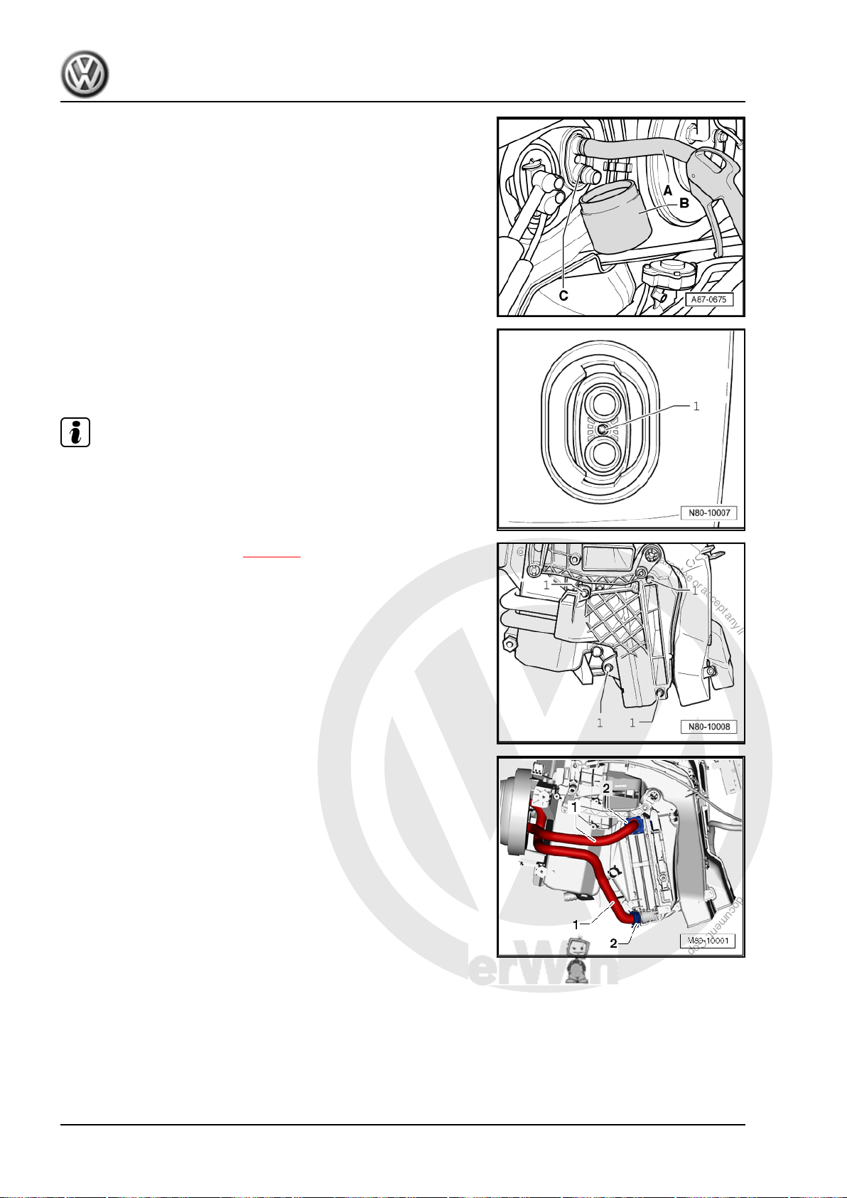
P
r
o
t
e
c
t
e
d
b
y
c
o
p
y
r
i
g
h
t
.
C
o
p
y
i
n
g
f
o
r
p
r
i
v
a
t
e
o
r
c
o
m
m
e
r
c
i
a
l
p
u
r
p
o
s
e
s
,
i
n
p
a
r
t
o
r
i
n
w
h
o
l
e
,
i
s
n
o
t
p
e
r
m
i
t
t
e
d
u
n
l
e
s
s
a
u
t
h
o
r
i
s
e
d
b
y
V
o
l
k
s
w
a
g
e
n
A
G
.
V
o
l
k
s
w
a
g
e
n
A
G
d
o
e
s
n
o
t
g
u
a
r
a
n
t
e
e
o
r
a
c
c
e
p
t
a
n
y
l
i
a
b
i
l
i
t
y
w
i
t
h
r
e
s
p
e
c
t
t
o
t
h
e
c
o
r
r
e
c
t
n
e
s
s
o
f
i
n
f
o
r
m
a
t
i
o
n
i
n
t
h
i
s
d
o
c
u
m
e
n
t
.
C
o
p
y
r
i
g
h
t
b
y
V
o
l
k
s
w
a
g
e
n
A
G
.
Golf Variant 2007 ➤ , Golf Variant 2010 ➤ , Jetta 2005 ➤ , Jetta 2011 ➤
Heating, air conditioning - Edition 04.2010
– Clamp off coolant hoses -1- with hose clamps up to 40 mm Ø
-VAS 3093- and disconnect coolant hoses to heat exchanger.
– Push a piece of hose -A- onto upper union of heat exchanger.
– Hold a container -B- under lower connection -C-.
– Using a compressed air pistol, carefully blow coolant out of
heat exchanger into container -B-.
– Undo bolt (6 mm hexagon socket head) -1- from union flange
between heat exchanger unions.
Note
This makes it possible to move the coolant pipes in order to re‐
move heat exchanger.
– Remove driver side footwell trim ⇒ Rep. gr. 68 .
– Remove left footwell vent ⇒ page 9 .
– Remove bolts -1- and remove heat exchanger cladding.
– Cover carpet in area under heat exchanger with waterproof foil
and water absorbing paper.
– Remove clips -2- and pull coolant pipes -1- out of heat ex‐
changer.
– Take heat exchanger out of heater unit.
24 Rep. gr.80 - Heating
Page 31
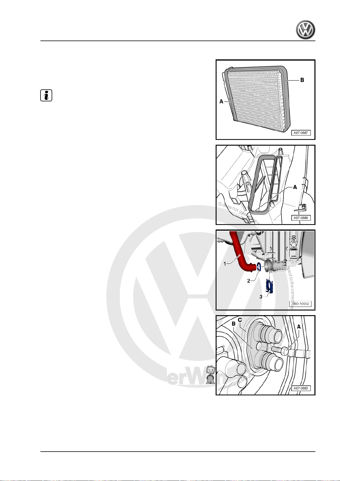
P
r
o
t
e
c
t
e
d
b
y
c
o
p
y
r
i
g
h
t
.
C
o
p
y
i
n
g
f
o
r
p
r
i
v
a
t
e
o
r
c
o
m
m
e
r
c
i
a
l
p
u
r
p
o
s
e
s
,
i
n
p
a
r
t
o
r
i
n
w
h
o
l
e
,
i
s
n
o
t
p
e
r
m
i
t
t
e
d
u
n
l
e
s
s
a
u
t
h
o
r
i
s
e
d
b
y
V
o
l
k
s
w
a
g
e
n
A
G
.
V
o
l
k
s
w
a
g
e
n
A
G
d
o
e
s
n
o
t
g
u
a
r
a
n
t
e
e
o
r
a
c
c
e
p
t
a
n
y
l
i
a
b
i
l
i
t
y
w
i
t
h
r
e
s
p
e
c
t
t
o
t
h
e
c
o
r
r
e
c
t
n
e
s
s
o
f
i
n
f
o
r
m
a
t
i
o
n
i
n
t
h
i
s
d
o
c
u
m
e
n
t
.
C
o
p
y
r
i
g
h
t
b
y
V
o
l
k
s
w
a
g
e
n
A
G
.
Golf Variant 2007 ➤ , Golf Variant 2010 ➤ , Jetta 2005 ➤ , Jetta 2011 ➤
Heating, air conditioning - Edition 04.2010
1.15.2 Installing
Install in reverse order. Note the following when doing this:
– Check seals attached to heat exchanger -A- and -B-. Install
heat exchanger only with undamaged seals.
Note
♦
An improperly bonded seal can roll up when heat exchanger
is pushed into heater unit.
♦
If seal is damaged or improperly attached, cold air can flow
past heat exchanger.
– Check heater unit for cleanliness through shaft -A- for heat
exchanger while heat exchanger is removed.
– If necessary, remove dirt or residue of leaked coolant from
heater unit, e.g. after removing a leaking heat exchanger.
– Slide heat exchanger into heater unit.
– Moisten seals -2- with coolant before installing.
– Seat seals -2- onto unions of coolant pipes -1-.
– Connect coolant pipes to heat exchanger.
– Install clips -3-.
– Screw bolt -A- into union flange -B- ensuring that bolt actually
screws into intended securing point.
1. Repairing heating system 25
Page 32
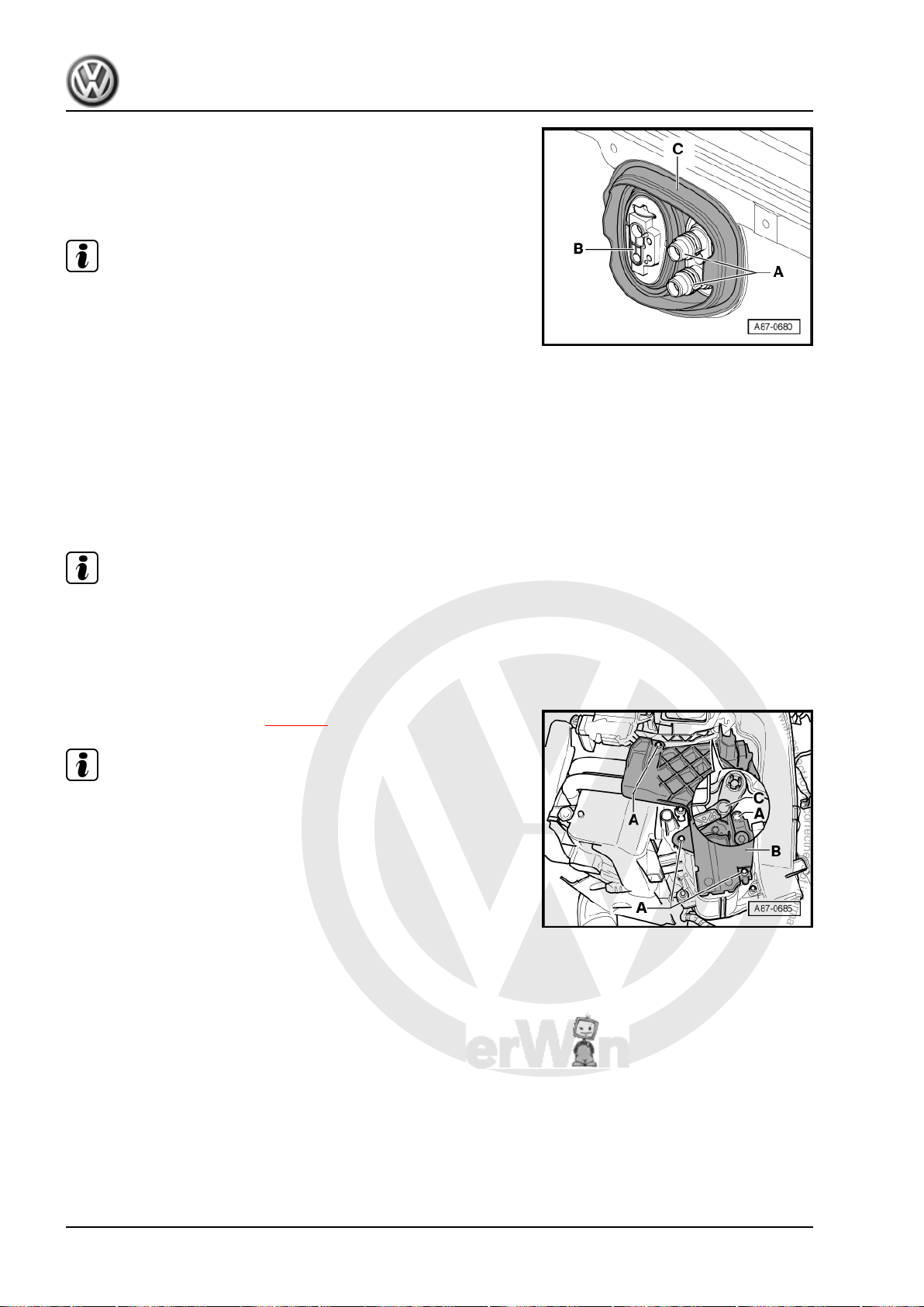
P
r
o
t
e
c
t
e
d
b
y
c
o
p
y
r
i
g
h
t
.
C
o
p
y
i
n
g
f
o
r
p
r
i
v
a
t
e
o
r
c
o
m
m
e
r
c
i
a
l
p
u
r
p
o
s
e
s
,
i
n
p
a
r
t
o
r
i
n
w
h
o
l
e
,
i
s
n
o
t
p
e
r
m
i
t
t
e
d
u
n
l
e
s
s
a
u
t
h
o
r
i
s
e
d
b
y
V
o
l
k
s
w
a
g
e
n
A
G
.
V
o
l
k
s
w
a
g
e
n
A
G
d
o
e
s
n
o
t
g
u
a
r
a
n
t
e
e
o
r
a
c
c
e
p
t
a
n
y
l
i
a
b
i
l
i
t
y
w
i
t
h
r
e
s
p
e
c
t
t
o
t
h
e
c
o
r
r
e
c
t
n
e
s
s
o
f
i
n
f
o
r
m
a
t
i
o
n
i
n
t
h
i
s
d
o
c
u
m
e
n
t
.
C
o
p
y
r
i
g
h
t
b
y
V
o
l
k
s
w
a
g
e
n
A
G
.
Golf Variant 2007 ➤ , Golf Variant 2010 ➤ , Jetta 2005 ➤ , Jetta 2011 ➤
Heating, air conditioning - Edition 04.2010
– Check grommet -C- is seating correctly in bulkhead.
– If necessary, seal flanges for coolant pipes to heat exchanger
-A- and for expansion valve (to evaporator, only vehicles with
air conditioning system) -B- at apertures in grommet -C- with
silicone adhesive sealant against water intrusion.
Note
♦
Always renew seals.
♦
Renew deformed hose clips.
♦
After renewing heat exchanger, renew coolant completely ⇒
Rep. gr. 19 .
♦
Check coolant circuit is not leaking. Pay particular attention to
unions/connections between coolant pipes and heat exchang‐
er.
1.16 Removing and installing auxiliary air heater element -Z35- , vehicles ► 1K-7M 119 726
Note
Installed only in vehicles with diesel engines without auxiliary
coolant heater.
1.16.1 Removing
– Remove driver side footwell trim ⇒ Rep. gr. 68 .
– Remove left footwell vent ⇒ page 9 .
Note
If the lever -C- to temperature flap is positioned so that the upper
bolt -A- is not accessible. Change position of temperature flap at
heater and fresh air controls. On vehicles with Climatronic, at
control and display unit e.g. setting „Hi“.
26 Rep. gr.80 - Heating
Page 33
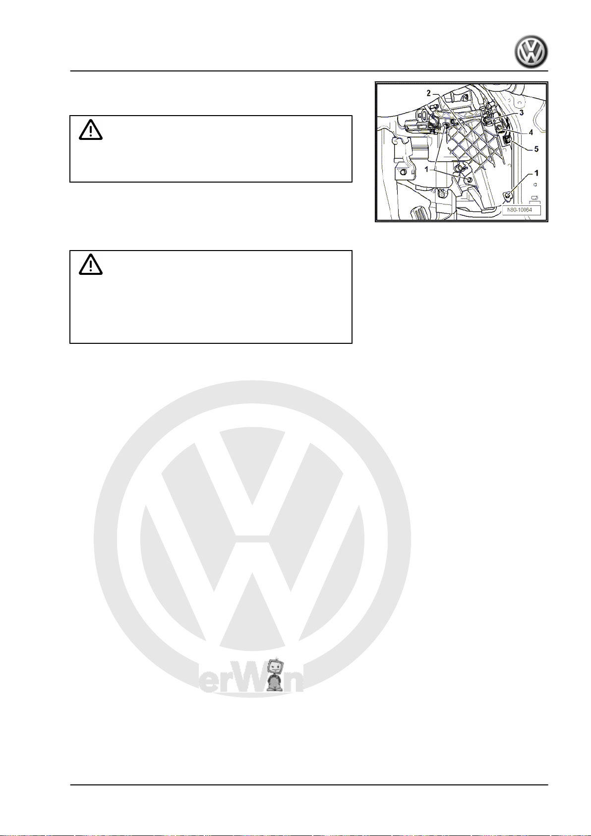
P
r
o
t
e
c
t
e
d
b
y
c
o
p
y
r
i
g
h
t
.
C
o
p
y
i
n
g
f
o
r
p
r
i
v
a
t
e
o
r
c
o
m
m
e
r
c
i
a
l
p
u
r
p
o
s
e
s
,
i
n
p
a
r
t
o
r
i
n
w
h
o
l
e
,
i
s
n
o
t
p
e
r
m
i
t
t
e
d
u
n
l
e
s
s
a
u
t
h
o
r
i
s
e
d
b
y
V
o
l
k
s
w
a
g
e
n
A
G
.
V
o
l
k
s
w
a
g
e
n
A
G
d
o
e
s
n
o
t
g
u
a
r
a
n
t
e
e
o
r
a
c
c
e
p
t
a
n
y
l
i
a
b
i
l
i
t
y
w
i
t
h
r
e
s
p
e
c
t
t
o
t
h
e
c
o
r
r
e
c
t
n
e
s
s
o
f
i
n
f
o
r
m
a
t
i
o
n
i
n
t
h
i
s
d
o
c
u
m
e
n
t
.
C
o
p
y
r
i
g
h
t
b
y
V
o
l
k
s
w
a
g
e
n
A
G
.
Golf Variant 2007 ➤ , Golf Variant 2010 ➤ , Jetta 2005 ➤ , Jetta 2011 ➤
Heating, air conditioning - Edition 04.2010
– Remove bolts -1- from cover -2-.
– Remove bolts -1- from cover -2-.
Caution
Danger of short circuit.
Disconnect battery before performing repair work.
– Remove securing nut for voltage supply -3- and earth con‐
nection -4- (6 ±1 Nm).
– Disconnect connector -5- from auxiliary air heater element -
Z35- .
WARNING
Danger of burn injuries.
The auxiliary air heater element -Z35- may be hot.
Before removing auxiliary air heater element -Z35- , allow it to
cool off.
– Pull auxiliary air heater element -Z35- out of heater unit.
1.16.2 Installing
Install in reverse order.
1.17 Checking, removing and installing aux‐
1.17.1 Checking auxiliary air heater element -
Auxiliary air heater element -Z35- with peripherals (load signal for
alternator terminal DF, low heat output relay -J359- , high heat
output relay -J360- , intake manifold temperature sender -G72- ,
coolant temperature sender -G62- ) can be read via the engine
control unit self-diagnosis.
1.17.2 Checking auxiliary air heater element -
Special tools and workshop equipment required
iliary air heater element -Z35- , vehicles
1K-7M 119 727 ►
Z35- with peripherals
Z35-
1. Repairing heating system 27
Page 34
P
r
o
t
e
c
t
e
d
b
y
c
o
p
y
r
i
g
h
t
.
C
o
p
y
i
n
g
f
o
r
p
r
i
v
a
t
e
o
r
c
o
m
m
e
r
c
i
a
l
p
u
r
p
o
s
e
s
,
i
n
p
a
r
t
o
r
i
n
w
h
o
l
e
,
i
s
n
o
t
p
e
r
m
i
t
t
e
d
u
n
l
e
s
s
a
u
t
h
o
r
i
s
e
d
b
y
V
o
l
k
s
w
a
g
e
n
A
G
.
V
o
l
k
s
w
a
g
e
n
A
G
d
o
e
s
n
o
t
g
u
a
r
a
n
t
e
e
o
r
a
c
c
e
p
t
a
n
y
l
i
a
b
i
l
i
t
y
w
i
t
h
r
e
s
p
e
c
t
t
o
t
h
e
c
o
r
r
e
c
t
n
e
s
s
o
f
i
n
f
o
r
m
a
t
i
o
n
i
n
t
h
i
s
d
o
c
u
m
e
n
t
.
C
o
p
y
r
i
g
h
t
b
y
V
o
l
k
s
w
a
g
e
n
A
G
.
Golf Variant 2007 ➤ , Golf Variant 2010 ➤ , Jetta 2005 ➤ , Jetta 2011 ➤
Heating, air conditioning - Edition 04.2010
♦ Vehicle diagnosis, testing and information system -VAS
5051B- with 100 A pick-up clamp -VAS 5051B/7-
1.17.3 Test conditions
• Intake temperature less than 19° C
• Coolant temperature less than 80° C
• Passenger compartment temperature about 20° C
• Battery voltage greater than 11 V
• Alternator load not greater than 50 % (terminal DF)
• Engine speed greater than 450 rpm
• Turn rotary knob for interior temperature to end position for
maximum temperature
1.17.4 Test procedure
– Remove left footwell vent ⇒ page 9 .
– Remove centre console trim from left footwell.
– Measure current consumption on earth wire -arrow- using ve‐
hicle diagnosis, testing and information system -VAS 5051Band 100 A pick-up clamp -VAS 5051B/7- .
Low heat output: ≈ 30 amps
Medium heat output: ≈ 60 amps
High heat output: ≈ 80 amps
1.17.5 Removing and installing
Removing
– Remove driver side footwell trim ⇒ Rep. gr. 68 .
28 Rep. gr.80 - Heating
Page 35
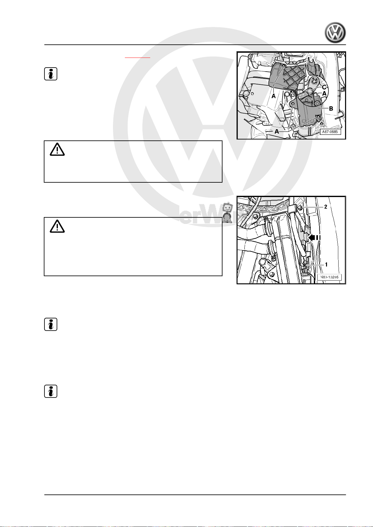
P
r
o
t
e
c
t
e
d
b
y
c
o
p
y
r
i
g
h
t
.
C
o
p
y
i
n
g
f
o
r
p
r
i
v
a
t
e
o
r
c
o
m
m
e
r
c
i
a
l
p
u
r
p
o
s
e
s
,
i
n
p
a
r
t
o
r
i
n
w
h
o
l
e
,
i
s
n
o
t
p
e
r
m
i
t
t
e
d
u
n
l
e
s
s
a
u
t
h
o
r
i
s
e
d
b
y
V
o
l
k
s
w
a
g
e
n
A
G
.
V
o
l
k
s
w
a
g
e
n
A
G
d
o
e
s
n
o
t
g
u
a
r
a
n
t
e
e
o
r
a
c
c
e
p
t
a
n
y
l
i
a
b
i
l
i
t
y
w
i
t
h
r
e
s
p
e
c
t
t
o
t
h
e
c
o
r
r
e
c
t
n
e
s
s
o
f
i
n
f
o
r
m
a
t
i
o
n
i
n
t
h
i
s
d
o
c
u
m
e
n
t
.
C
o
p
y
r
i
g
h
t
b
y
V
o
l
k
s
w
a
g
e
n
A
G
.
Golf Variant 2007 ➤ , Golf Variant 2010 ➤ , Jetta 2005 ➤ , Jetta 2011 ➤
– Remove left footwell vent ⇒ page 9 .
Note
If the lever -C- to temperature flap is positioned so that the upper
bolt -A- is not accessible. Change position of temperature flap at
heater and fresh air controls. On vehicles with Climatronic, at
control and display unit e.g. setting „Hi“.
– Disconnect battery ⇒ Rep. gr. 27 .
– Remove bolts -A- from cover -B-.
Caution
Danger of short circuit.
Disconnect battery before performing repair work.
– Remove nut -1- 9 ±1 Nm.
– Release locking device of connector strip -arrow-.
WARNING
Danger of burn injuries.
Heating, air conditioning - Edition 04.2010
The auxiliary air heater element -Z35- may be hot.
Before removing auxiliary air heater element -Z35- , allow it to
cool off.
– Undo bolt -2- 1.4 Nm and pull auxiliary air heater element -
Z35- out of blower box.
Installing
Note
Ensure that the earth wire is in proper position.
Install in reverse order.
1.18 Checking ventilation
Note
♦
The stale air escapes via ventilation openings in the luggage
compartment trim.
♦
If the ventilation is to function properly, the exhaust openings
must not be covered.
♦
The ventilation frames are located in the rear side panels be‐
hind the bumper.
1. Repairing heating system 29
Page 36
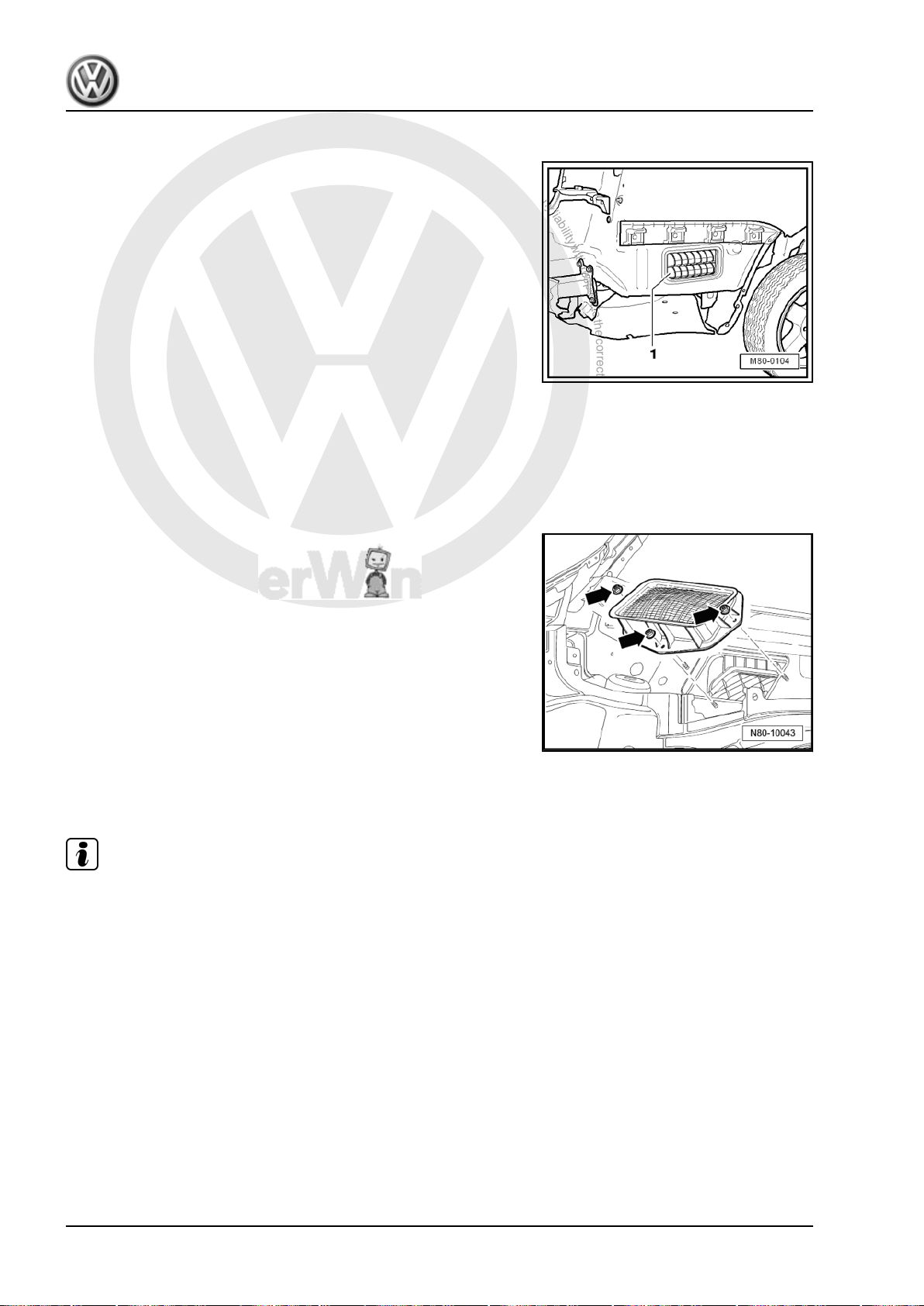
P
r
o
t
e
c
t
e
d
b
y
c
o
p
y
r
i
g
h
t
.
C
o
p
y
i
n
g
f
o
r
p
r
i
v
a
t
e
o
r
c
o
m
m
e
r
c
i
a
l
p
u
r
p
o
s
e
s
,
i
n
p
a
r
t
o
r
i
n
w
h
o
l
e
,
i
s
n
o
t
p
e
r
m
i
t
t
e
d
u
n
l
e
s
s
a
u
t
h
o
r
i
s
e
d
b
y
V
o
l
k
s
w
a
g
e
n
A
G
.
V
o
l
k
s
w
a
g
e
n
A
G
d
o
e
s
n
o
t
g
u
a
r
a
n
t
e
e
o
r
a
c
c
e
p
t
a
n
y
l
i
a
b
i
l
i
t
y
w
i
t
h
r
e
s
p
e
c
t
t
o
t
h
e
c
o
r
r
e
c
t
n
e
s
s
o
f
i
n
f
o
r
m
a
t
i
o
n
i
n
t
h
i
s
d
o
c
u
m
e
n
t
.
C
o
p
y
r
i
g
h
t
b
y
V
o
l
k
s
w
a
g
e
n
A
G
.
Golf Variant 2007 ➤ , Golf Variant 2010 ➤ , Jetta 2005 ➤ , Jetta 2011 ➤
Heating, air conditioning - Edition 04.2010
1.18.1 Checking
– Remove rear bumper ⇒ Rep. gr. 63 .
– Sealing lips -1- in ventilation frames on both sides of vehicle
must be free to move and close by themselves.
– Note installation position.
1.19 Removing and installing air intake grille
1.19.1 Removing
– Remove plenum chamber cover ⇒ Rep. gr. 64 .
– Remove securing nuts -arrows- and remove air intake grille
upwards.
(Golf Variant 2007►, Golf Variant 2010►
und Jetta 2005►)
1.19.2 Installing
Install in reverse order.
Note
Seal must seat properly on air intake grille.
1.20 Removing and installing air intake grille (Jetta 2010►)
1.20.1 Removing
– Remove plenum chamber cover ⇒ Rep. gr. 64 .
30 Rep. gr.80 - Heating
Page 37
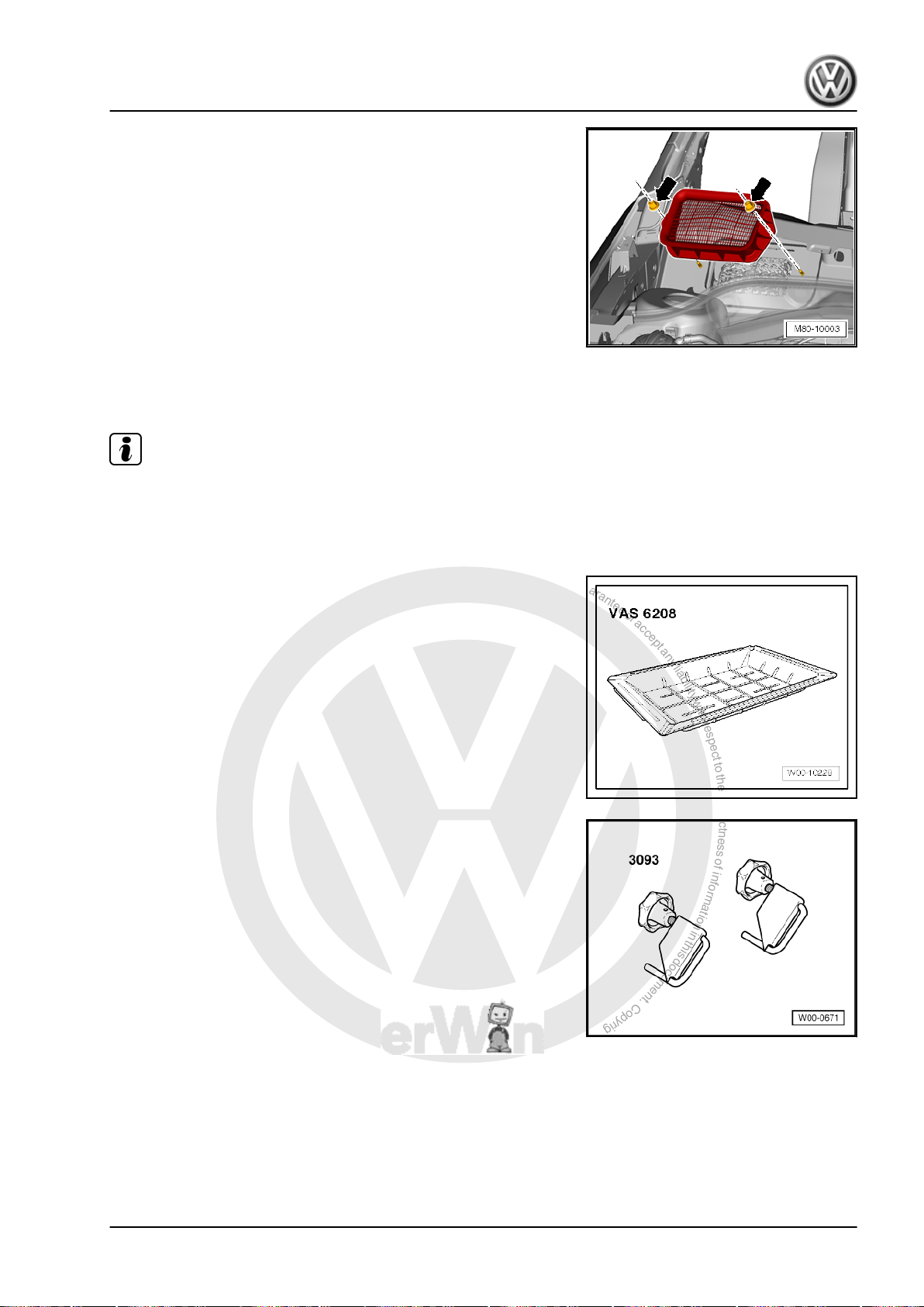
P
r
o
t
e
c
t
e
d
b
y
c
o
p
y
r
i
g
h
t
.
C
o
p
y
i
n
g
f
o
r
p
r
i
v
a
t
e
o
r
c
o
m
m
e
r
c
i
a
l
p
u
r
p
o
s
e
s
,
i
n
p
a
r
t
o
r
i
n
w
h
o
l
e
,
i
s
n
o
t
p
e
r
m
i
t
t
e
d
u
n
l
e
s
s
a
u
t
h
o
r
i
s
e
d
b
y
V
o
l
k
s
w
a
g
e
n
A
G
.
V
o
l
k
s
w
a
g
e
n
A
G
d
o
e
s
n
o
t
g
u
a
r
a
n
t
e
e
o
r
a
c
c
e
p
t
a
n
y
l
i
a
b
i
l
i
t
y
w
i
t
h
r
e
s
p
e
c
t
t
o
t
h
e
c
o
r
r
e
c
t
n
e
s
s
o
f
i
n
f
o
r
m
a
t
i
o
n
i
n
t
h
i
s
d
o
c
u
m
e
n
t
.
C
o
p
y
r
i
g
h
t
b
y
V
o
l
k
s
w
a
g
e
n
A
G
.
Golf Variant 2007 ➤ , Golf Variant 2010 ➤ , Jetta 2005 ➤ , Jetta 2011 ➤
Heating, air conditioning - Edition 04.2010
– Remove securing nuts -arrows- and remove air intake grille
upwards.
1.20.2 Installing
Install in reverse order.
Note
Seal must seat properly on air intake grille.
1.21 Removing and installing heater unit
Special tools and workshop equipment required
♦ Drip tray for workshop hoist -VAS 6208-
♦ Hose clamps up to 40 mm Ø -VAS 3093-
♦ Compressed air gun, commercially available
1. Repairing heating system 31
Page 38
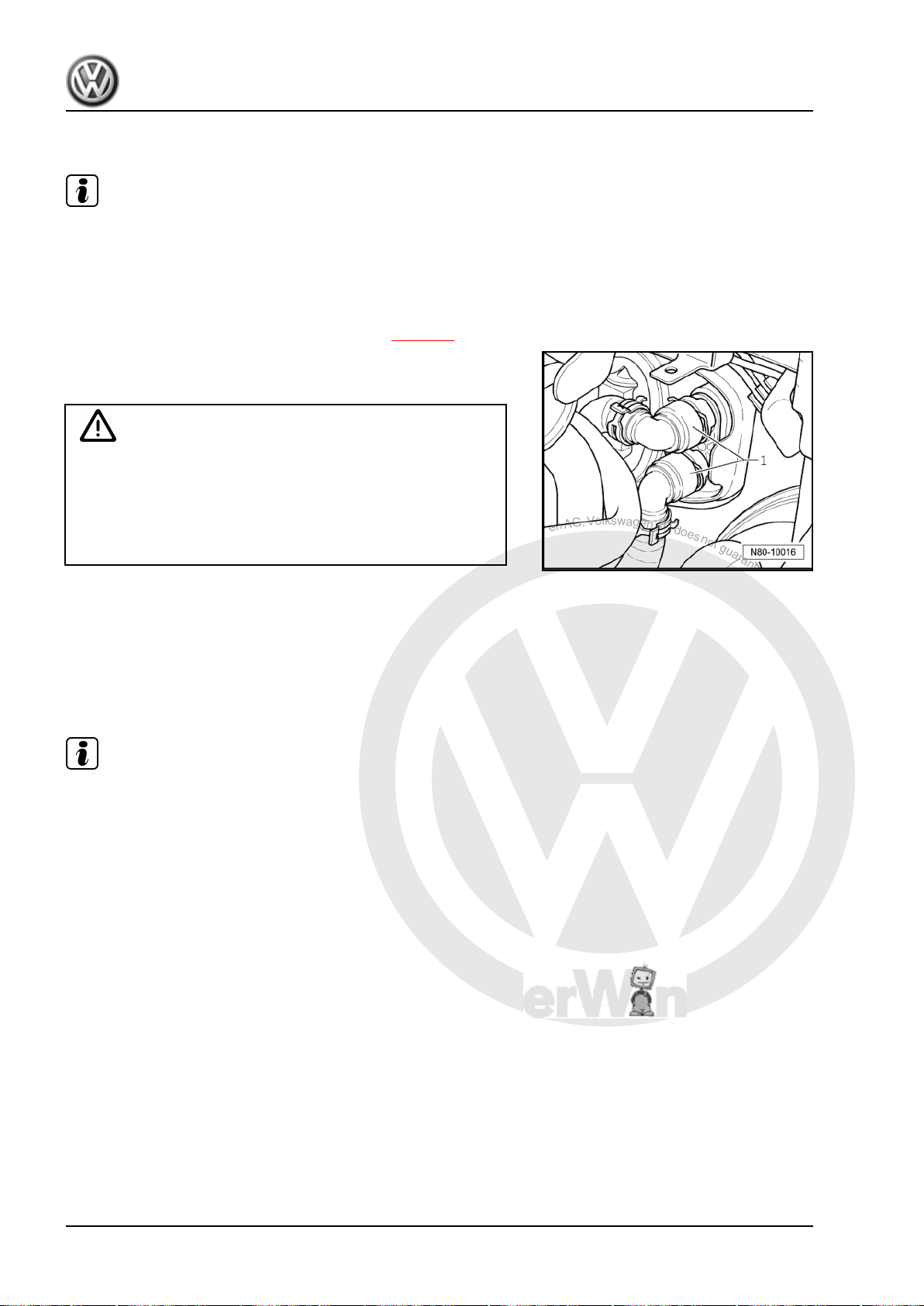
P
r
o
t
e
c
t
e
d
b
y
c
o
p
y
r
i
g
h
t
.
C
o
p
y
i
n
g
f
o
r
p
r
i
v
a
t
e
o
r
c
o
m
m
e
r
c
i
a
l
p
u
r
p
o
s
e
s
,
i
n
p
a
r
t
o
r
i
n
w
h
o
l
e
,
i
s
n
o
t
p
e
r
m
i
t
t
e
d
u
n
l
e
s
s
a
u
t
h
o
r
i
s
e
d
b
y
V
o
l
k
s
w
a
g
e
n
A
G
.
V
o
l
k
s
w
a
g
e
n
A
G
d
o
e
s
n
o
t
g
u
a
r
a
n
t
e
e
o
r
a
c
c
e
p
t
a
n
y
l
i
a
b
i
l
i
t
y
w
i
t
h
r
e
s
p
e
c
t
t
o
t
h
e
c
o
r
r
e
c
t
n
e
s
s
o
f
i
n
f
o
r
m
a
t
i
o
n
i
n
t
h
i
s
d
o
c
u
m
e
n
t
.
C
o
p
y
r
i
g
h
t
b
y
V
o
l
k
s
w
a
g
e
n
A
G
.
Golf Variant 2007 ➤ , Golf Variant 2010 ➤ , Jetta 2005 ➤ , Jetta 2011 ➤
Heating, air conditioning - Edition 04.2010
1.21.1 Removing
Note
To improve access, depending on engine version, additional com‐
ponents, e.g. engine cover must be removed ⇒ Rep. gr. 10 .
– Remove dash panel ⇒ Rep. gr. 70 .
– Remove bulkhead in plenum chamber ⇒ Rep. gr. 50 .
– Remove left and right rear footwell air ducts ⇒ page 8 .
– Place drip tray -VAS 6208- beneath engine.
– Mark coolant hoses -1-.
WARNING
Danger of scalding injuries.
When the engine is warm, the coolant temperature may be
above 100 °C. The cooling system is pressurised.
If necessary, release pressure and reduce temperature before
carrying out repairs.
– Clamp off coolant hoses -1- with hose clamps up to 40 mm Ø
-VAS 3093- and disconnect coolant hoses to heat exchanger.
– Carefully blow remaining coolant out through unions of heat
exchanger using a compressed air pistol.
– Cover carpet in interior of vehicle with a waterproof foil and
water absorbing paper.
Note
During removal, note lengths and locations of bolts for later installation.
32 Rep. gr.80 - Heating
Page 39
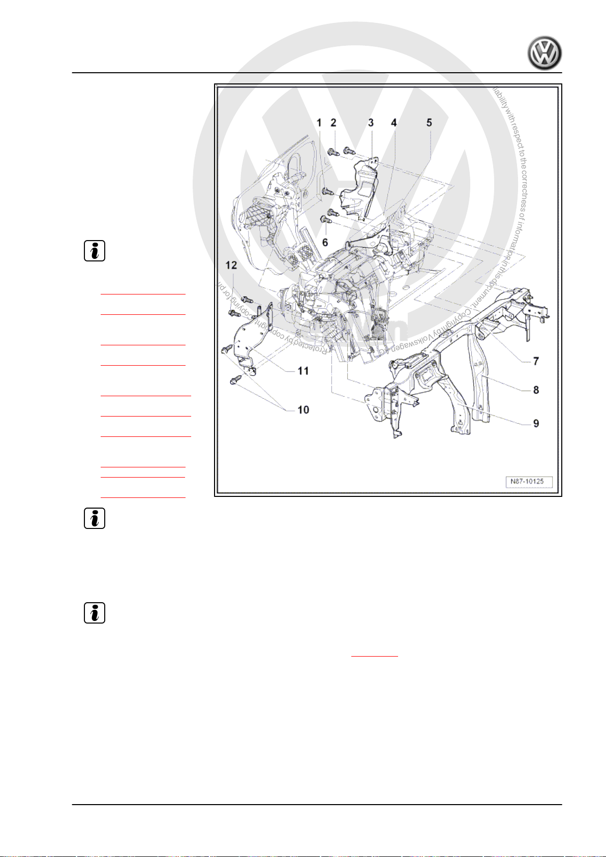
P
r
o
t
e
c
t
e
d
b
y
c
o
p
y
r
i
g
h
t
.
C
o
p
y
i
n
g
f
o
r
p
r
i
v
a
t
e
o
r
c
o
m
m
e
r
c
i
a
l
p
u
r
p
o
s
e
s
,
i
n
p
a
r
t
o
r
i
n
w
h
o
l
e
,
i
s
n
o
t
p
e
r
m
i
t
t
e
d
u
n
l
e
s
s
a
u
t
h
o
r
i
s
e
d
b
y
V
o
l
k
s
w
a
g
e
n
A
G
.
V
o
l
k
s
w
a
g
e
n
A
G
d
o
e
s
n
o
t
g
u
a
r
a
n
t
e
e
o
r
a
c
c
e
p
t
a
n
y
l
i
a
b
i
l
i
t
y
w
i
t
h
r
e
s
p
e
c
t
t
o
t
h
e
c
o
r
r
e
c
t
n
e
s
s
o
f
i
n
f
o
r
m
a
t
i
o
n
i
n
t
h
i
s
d
o
c
u
m
e
n
t
.
C
o
p
y
r
i
g
h
t
b
y
V
o
l
k
s
w
a
g
e
n
A
G
.
1 - Bolt
❑ 4 Nm
2 - Bolts
❑ Qty. 2
❑ 4 Nm
3 - Cable retainer
4 - Heater unit
❑ Removing:
– Disconnect connectors
on heater unit.
Note
– Undo bolts
⇒ Item 6 (page 33)
from bracket
⇒ Item 5 (page 33) .
– Remove supports
⇒ Item 8 (page 33)
and
⇒ Item 9 (page 33) .
– Remove bolts
⇒ Item 10 (page 33)
and
⇒ Item 12 (page 34)
and remove bracket
⇒ Item 11 (page 34) .
Golf Variant 2007 ➤ , Golf Variant 2010 ➤ , Jetta 2005 ➤ , Jetta 2011 ➤
Heating, air conditioning - Edition 04.2010
– Undo bolts
⇒ Item 1 (page 33) and
⇒ Item 2 (page 33) from
cable retainer
⇒ Item 3 (page 33) .
Note
– Remove heater unit.
Installing:
Install in reverse order. Note the following when doing this:
Note
Second mechanic must guide both coolant pipes though seal in engine compartment, from engine com‐
–
partment, to heat exchanger when installing heater unit ⇒ page 34 .
– Fill with coolant ⇒ Rep. gr. 19 .
5 - Bracket
6 - Bolts
❑ 8 Nm
7 - Assembly carrier
8 - Right support
9 - Left support
1. Repairing heating system 33
Page 40
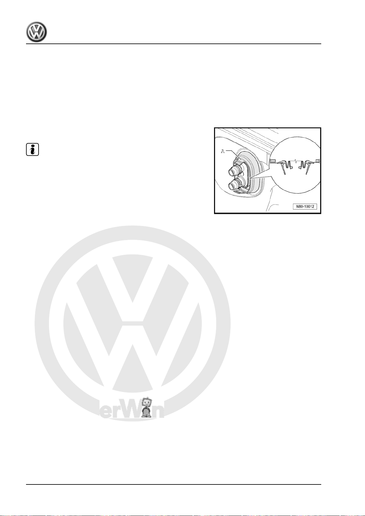
P
r
o
t
e
c
t
e
d
b
y
c
o
p
y
r
i
g
h
t
.
C
o
p
y
i
n
g
f
o
r
p
r
i
v
a
t
e
o
r
c
o
m
m
e
r
c
i
a
l
p
u
r
p
o
s
e
s
,
i
n
p
a
r
t
o
r
i
n
w
h
o
l
e
,
i
s
n
o
t
p
e
r
m
i
t
t
e
d
u
n
l
e
s
s
a
u
t
h
o
r
i
s
e
d
b
y
V
o
l
k
s
w
a
g
e
n
A
G
.
V
o
l
k
s
w
a
g
e
n
A
G
d
o
e
s
n
o
t
g
u
a
r
a
n
t
e
e
o
r
a
c
c
e
p
t
a
n
y
l
i
a
b
i
l
i
t
y
w
i
t
h
r
e
s
p
e
c
t
t
o
t
h
e
c
o
r
r
e
c
t
n
e
s
s
o
f
i
n
f
o
r
m
a
t
i
o
n
i
n
t
h
i
s
d
o
c
u
m
e
n
t
.
C
o
p
y
r
i
g
h
t
b
y
V
o
l
k
s
w
a
g
e
n
A
G
.
Golf Variant 2007 ➤ , Golf Variant 2010 ➤ , Jetta 2005 ➤ , Jetta 2011 ➤
Heating, air conditioning - Edition 04.2010
10 - Bolts
❑ Qty. 2
❑ 8 Nm
11 - Bracket
12 - Bolts
❑ Qty. 2
❑ 8 Nm
Seal between heater unit and engine compartment
Note
Observe position of seal -A- during installation.
34 Rep. gr.80 - Heating
Page 41
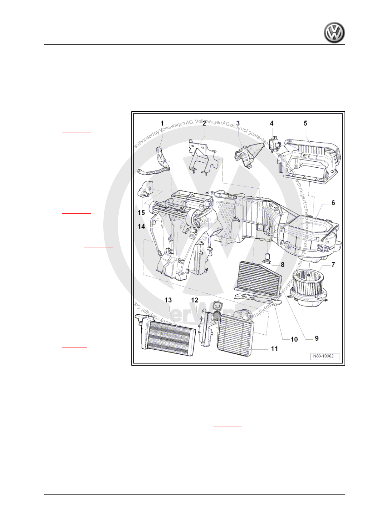
P
r
o
t
e
c
t
e
d
b
y
c
o
p
y
r
i
g
h
t
.
C
o
p
y
i
n
g
f
o
r
p
r
i
v
a
t
e
o
r
c
o
m
m
e
r
c
i
a
l
p
u
r
p
o
s
e
s
,
i
n
p
a
r
t
o
r
i
n
w
h
o
l
e
,
i
s
n
o
t
p
e
r
m
i
t
t
e
d
u
n
l
e
s
s
a
u
t
h
o
r
i
s
e
d
b
y
V
o
l
k
s
w
a
g
e
n
A
G
.
V
o
l
k
s
w
a
g
e
n
A
G
d
o
e
s
n
o
t
g
u
a
r
a
n
t
e
e
o
r
a
c
c
e
p
t
a
n
y
l
i
a
b
i
l
i
t
y
w
i
t
h
r
e
s
p
e
c
t
t
o
t
h
e
c
o
r
r
e
c
t
n
e
s
s
o
f
i
n
f
o
r
m
a
t
i
o
n
i
n
t
h
i
s
d
o
c
u
m
e
n
t
.
C
o
p
y
r
i
g
h
t
b
y
V
o
l
k
s
w
a
g
e
n
A
G
.
Golf Variant 2007 ➤ , Golf Variant 2010 ➤ , Jetta 2005 ➤ , Jetta 2011 ➤
Heating, air conditioning - Edition 04.2010
2 Dismantling and assembling heater
unit
2.1 Dismantling and assembling heater unit
1 - Temperature flap actuator
❑ Removing and installing
⇒ page 36
2 - Bracket
3 - Cover
4 - Fresh air and air recircula‐
tion flap control motor -V154-
❑ Checking: vehicle diag‐
nosis, testing and infor‐
mation system -VAS
5051B- .
❑ Removing and installing
⇒ page 79
❑ Renewing: initiate basic
setting using vehicle di‐
agnosis, testing and in‐
formation system -VAS
5051B- ⇒ page 55 .
5 - Air intake housing
❑ With air recirculation
flap
6 - Heater unit
7 - Fresh air blower -V2-
❑ Removing and installing
⇒ page 5
8 - Fresh air blower series re‐
sistor with overheating fuse N24-
❑ Removing and installing
⇒ page 6
9 - Dust and pollen filter
❑ Removing and installing
⇒ page 6
10 - Cover
❑ For dust and pollen filter.
11 - Heat exchanger
❑ Removing and installing heat exchanger (Golf Variant 2007►, Golf Variant 2010► und Jetta 2005►)
⇒ page 19 .
❑ Removing and installing heat exchanger (Jetta 2010►) ⇒ page 23 .
❑ After renewing heat exchanger, renew coolant completely ⇒ Rep. gr. 19 .
12 - Heat exchanger trim
13 - Auxiliary air heater element -Z35-
Vehicles ► 1K-7M 119 726
❑ With auxiliary air heater control unit -J604- .
2. Dismantling and assembling heater unit 35
Page 42
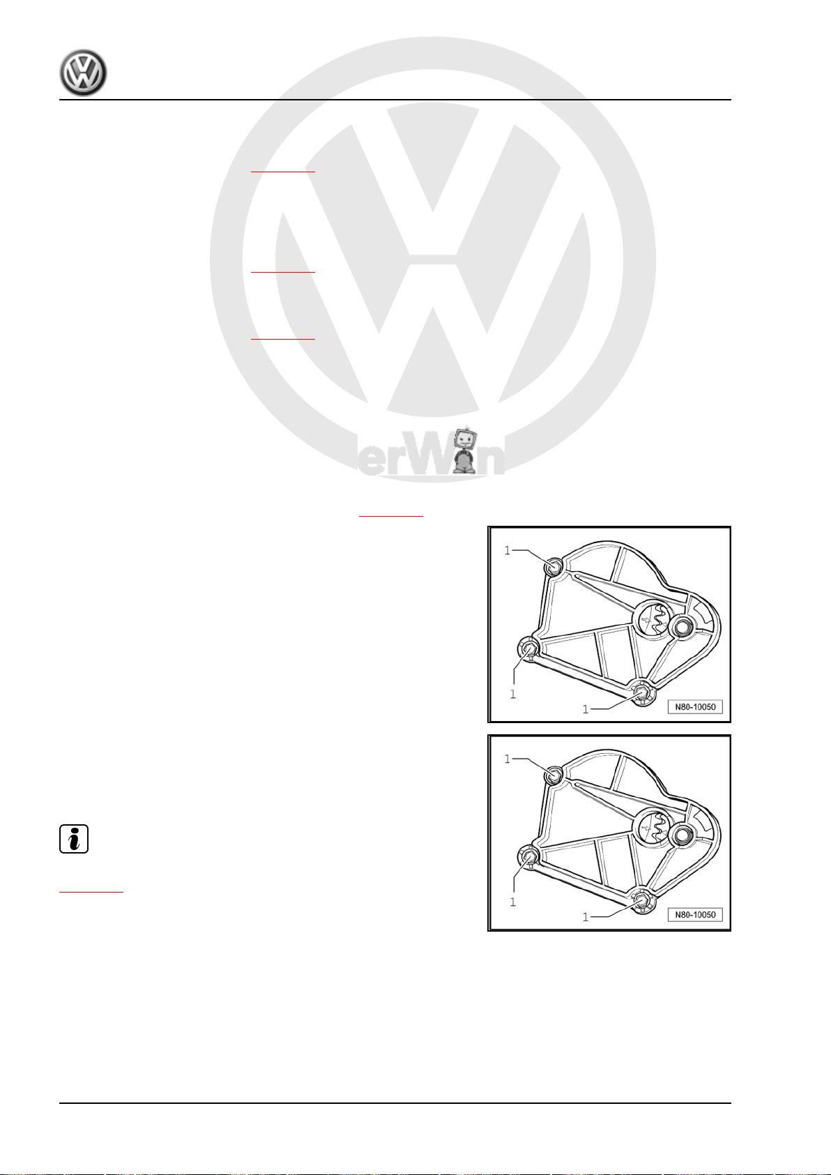
P
r
o
t
e
c
t
e
d
b
y
c
o
p
y
r
i
g
h
t
.
C
o
p
y
i
n
g
f
o
r
p
r
i
v
a
t
e
o
r
c
o
m
m
e
r
c
i
a
l
p
u
r
p
o
s
e
s
,
i
n
p
a
r
t
o
r
i
n
w
h
o
l
e
,
i
s
n
o
t
p
e
r
m
i
t
t
e
d
u
n
l
e
s
s
a
u
t
h
o
r
i
s
e
d
b
y
V
o
l
k
s
w
a
g
e
n
A
G
.
V
o
l
k
s
w
a
g
e
n
A
G
d
o
e
s
n
o
t
g
u
a
r
a
n
t
e
e
o
r
a
c
c
e
p
t
a
n
y
l
i
a
b
i
l
i
t
y
w
i
t
h
r
e
s
p
e
c
t
t
o
t
h
e
c
o
r
r
e
c
t
n
e
s
s
o
f
i
n
f
o
r
m
a
t
i
o
n
i
n
t
h
i
s
d
o
c
u
m
e
n
t
.
C
o
p
y
r
i
g
h
t
b
y
V
o
l
k
s
w
a
g
e
n
A
G
.
Golf Variant 2007 ➤ , Golf Variant 2010 ➤ , Jetta 2005 ➤ , Jetta 2011 ➤
Heating, air conditioning - Edition 04.2010
❑ Checking: with vehicle diagnosis, testing and information system -VAS 5051- (or later model), under
Heating, ventilation, air conditioning; Systems capable of self-diagnosis; Auxiliary heating; Electrical
components.
❑ Removing and installing ⇒ page 26
Vehicles 1K-7M 119 726 ►
❑ A three-level auxiliary air heater element -Z35- is fitted here; it is controlled by the respective engine
control unit via relays.
❑ Installed only in vehicles with diesel engines without supplementary heater.
❑ Removing and installing ⇒ page 27
14 - Air distribution housing
15 - Air distribution flap actuator
❑ Removing and installing ⇒ page 36
2.2 Removing and installing air distribution flap actuator
2.2.1 Removing
– Remove dash panel ⇒ Rep. gr. 70 .
– Unclip flexible shaft from adapter for controls ⇒ page 50 .
– Remove bolts -1- and remove air distribution flap actuator.
2.2.2 Installing
– Arrows on gears must align.
– Position air distribution flap actuator and tighten bolts -1-.
Note
After installation, check operation of air distribution flap
⇒ page 50 .
2.3 Removing and installing temperature flap actuator
2.3.1 Removing
– Remove driver side footwell trim ⇒ Rep. gr. 68 .
36 Rep. gr.80 - Heating
Page 43
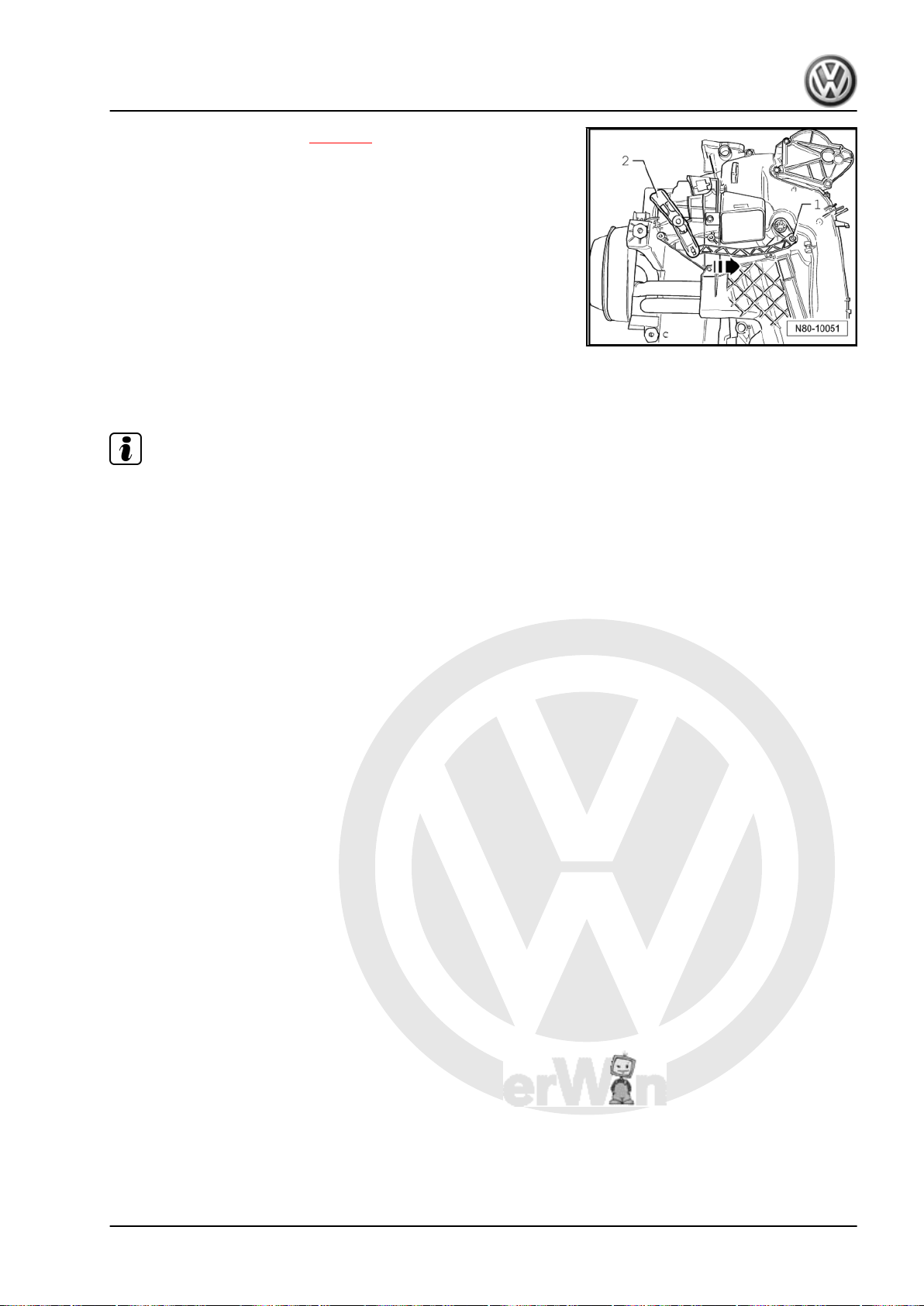
P
r
o
t
e
c
t
e
d
b
y
c
o
p
y
r
i
g
h
t
.
C
o
p
y
i
n
g
f
o
r
p
r
i
v
a
t
e
o
r
c
o
m
m
e
r
c
i
a
l
p
u
r
p
o
s
e
s
,
i
n
p
a
r
t
o
r
i
n
w
h
o
l
e
,
i
s
n
o
t
p
e
r
m
i
t
t
e
d
u
n
l
e
s
s
a
u
t
h
o
r
i
s
e
d
b
y
V
o
l
k
s
w
a
g
e
n
A
G
.
V
o
l
k
s
w
a
g
e
n
A
G
d
o
e
s
n
o
t
g
u
a
r
a
n
t
e
e
o
r
a
c
c
e
p
t
a
n
y
l
i
a
b
i
l
i
t
y
w
i
t
h
r
e
s
p
e
c
t
t
o
t
h
e
c
o
r
r
e
c
t
n
e
s
s
o
f
i
n
f
o
r
m
a
t
i
o
n
i
n
t
h
i
s
d
o
c
u
m
e
n
t
.
C
o
p
y
r
i
g
h
t
b
y
V
o
l
k
s
w
a
g
e
n
A
G
.
Golf Variant 2007 ➤ , Golf Variant 2010 ➤ , Jetta 2005 ➤ , Jetta 2011 ➤
Heating, air conditioning - Edition 04.2010
– Remove left footwell vent ⇒ page 9 .
– Unclip cable on temperature flap actuator -2-.
– Release catch -1- and press temperature flap actuator in
-direction of arrow- to stop.
– Pull off temperature flap actuator.
2.3.2 Installing
Install in reverse order.
Note
After installation, check operation of temperature flap. Tempera‐
ture knob of control for heated and fresh air must move freely and
without jerking from „cold“ position to „warm“ position.
2. Dismantling and assembling heater unit 37
Page 44

P
r
o
t
e
c
t
e
d
b
y
c
o
p
y
r
i
g
h
t
.
C
o
p
y
i
n
g
f
o
r
p
r
i
v
a
t
e
o
r
c
o
m
m
e
r
c
i
a
l
p
u
r
p
o
s
e
s
,
i
n
p
a
r
t
o
r
i
n
w
h
o
l
e
,
i
s
n
o
t
p
e
r
m
i
t
t
e
d
u
n
l
e
s
s
a
u
t
h
o
r
i
s
e
d
b
y
V
o
l
k
s
w
a
g
e
n
A
G
.
V
o
l
k
s
w
a
g
e
n
A
G
d
o
e
s
n
o
t
g
u
a
r
a
n
t
e
e
o
r
a
c
c
e
p
t
a
n
y
l
i
a
b
i
l
i
t
y
w
i
t
h
r
e
s
p
e
c
t
t
o
t
h
e
c
o
r
r
e
c
t
n
e
s
s
o
f
i
n
f
o
r
m
a
t
i
o
n
i
n
t
h
i
s
d
o
c
u
m
e
n
t
.
C
o
p
y
r
i
g
h
t
b
y
V
o
l
k
s
w
a
g
e
n
A
G
.
Golf Variant 2007 ➤ , Golf Variant 2010 ➤ , Jetta 2005 ➤ , Jetta 2011 ➤
Heating, air conditioning - Edition 04.2010
87 – Air conditioning system
1 Notes on repair work to vehicles with
air conditioning and on handling re‐
frigerant
Note
♦
Notes on repair work to vehicles with air conditioning and on
handling refrigerant can be found in ELSA under repair group
⇒ Rep. gr. 00 ; Technical information "Air conditioning system
- with refrigerant R134a VW" .
♦
Notes on tools for repairs to vehicles with air conditioning and
on handling refrigerant can be found in ELSA under repair
group ⇒ Rep. gr. 00 ; Technical information "Air conditioning
system - with refrigerant R134a VW" .
♦
The version in ELSA under the Internet button is no longer
valid.
Additional information:
♦ ⇒ Current flow diagrams, Electrical fault finding and Fitting lo‐
cations
♦ Repairs to evacuated refrigerant circuit that can only be car‐
ried out by specially trained mechanics at specialist service
stations ⇒ Service Organisation Handbook (SOH) Volume 1a;
Chapter 6.4 Workshop Equipment; Tools .
38 Rep. gr.87 - Air conditioning system
Page 45
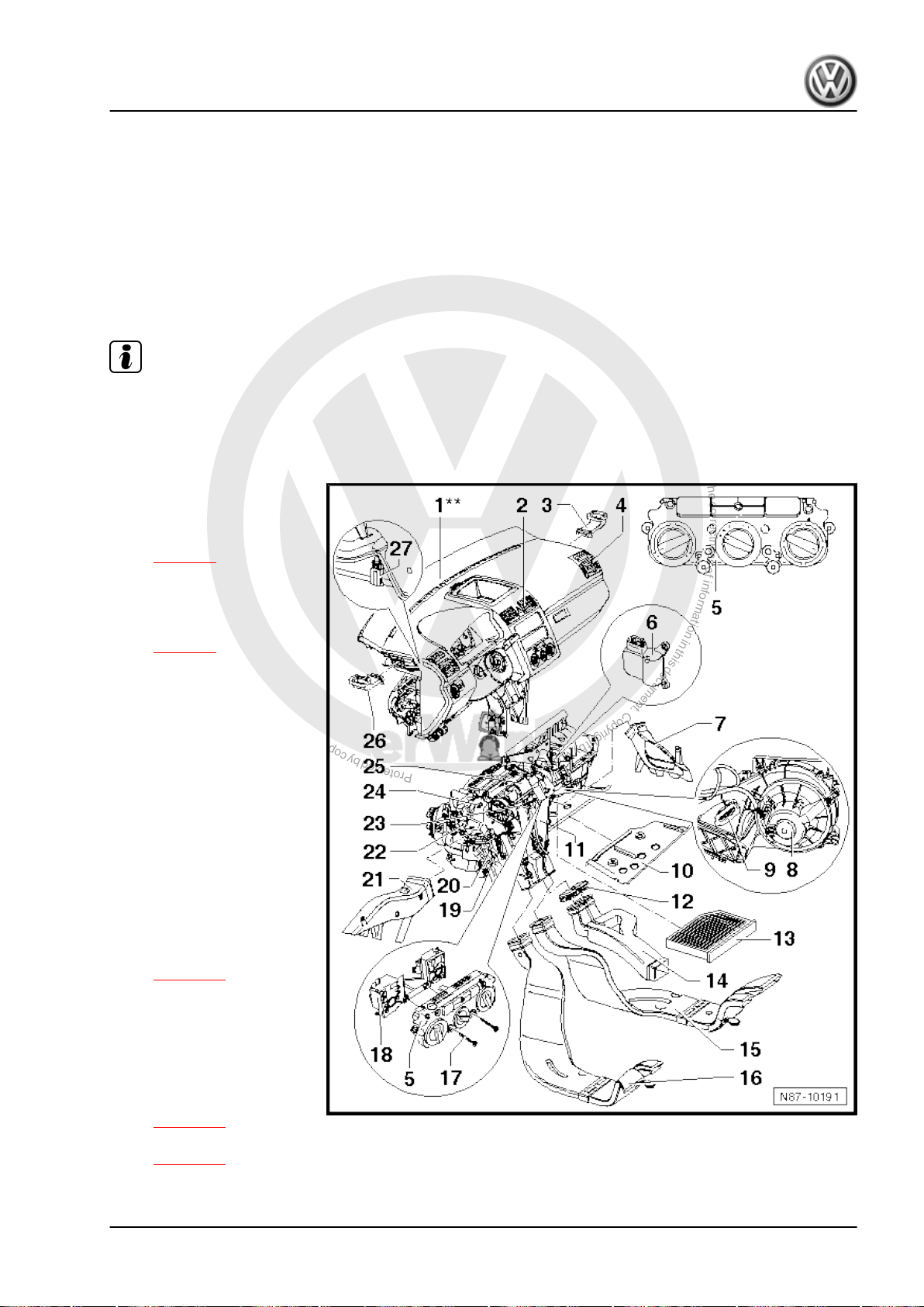
P
r
o
t
e
c
t
e
d
b
y
c
o
p
y
r
i
g
h
t
.
C
o
p
y
i
n
g
f
o
r
p
r
i
v
a
t
e
o
r
c
o
m
m
e
r
c
i
a
l
p
u
r
p
o
s
e
s
,
i
n
p
a
r
t
o
r
i
n
w
h
o
l
e
,
i
s
n
o
t
p
e
r
m
i
t
t
e
d
u
n
l
e
s
s
a
u
t
h
o
r
i
s
e
d
b
y
V
o
l
k
s
w
a
g
e
n
A
G
.
V
o
l
k
s
w
a
g
e
n
A
G
d
o
e
s
n
o
t
g
u
a
r
a
n
t
e
e
o
r
a
c
c
e
p
t
a
n
y
l
i
a
b
i
l
i
t
y
w
i
t
h
r
e
s
p
e
c
t
t
o
t
h
e
c
o
r
r
e
c
t
n
e
s
s
o
f
i
n
f
o
r
m
a
t
i
o
n
i
n
t
h
i
s
d
o
c
u
m
e
n
t
.
C
o
p
y
r
i
g
h
t
b
y
V
o
l
k
s
w
a
g
e
n
A
G
.
Golf Variant 2007 ➤ , Golf Variant 2010 ➤ , Jetta 2005 ➤ , Jetta 2011 ➤
Heating, air conditioning - Edition 04.2010
2 Air conditioning system with manual
controls, Climatic
2.1 Air conditioning system and heater passenger compartment (Golf Variant
2007►, Golf Variant 2010► und Jetta
2005►)
Note
♦
Disconnect battery before removing components marked ** ⇒
Rep. gr. 27 .
♦
A label indicates the type and quantity of refrigerant used.
1 - Dash panel**
2 - Centre vents
❑ Removing and installing
⇒ page 7
3 - Right side vent
4 - Right vent
❑ Removing and installing
⇒ page 8
5 - Heating and air conditioning
controls, Climatic
❑ With fresh air and air re‐
circulation flap switch E159- .
❑ With heated rear win‐
dow button -E230- .
❑ With fresh air blower
switch -E9-
❑ With air conditioning
system control unit J301- .
❑ For vehicles with sup‐
plementary heating hav‐
ing instant heating but‐
ton -E537- .
❑ Removing and installing
⇒ page 48
6 - Air recirculation flap control
motor -V113-
❑ Checking: vehicle diag‐
nosis, testing and infor‐
mation system -VAS
5051B- .
❑ Removing and installing
⇒ page 51
❑ Renewing: initiate basic setting using vehicle diagnosis, testing and information system -VAS 5051B-
⇒ page 55 .
2. Air conditioning system with manual controls, Climatic 39
Page 46

P
r
o
t
e
c
t
e
d
b
y
c
o
p
y
r
i
g
h
t
.
C
o
p
y
i
n
g
f
o
r
p
r
i
v
a
t
e
o
r
c
o
m
m
e
r
c
i
a
l
p
u
r
p
o
s
e
s
,
i
n
p
a
r
t
o
r
i
n
w
h
o
l
e
,
i
s
n
o
t
p
e
r
m
i
t
t
e
d
u
n
l
e
s
s
a
u
t
h
o
r
i
s
e
d
b
y
V
o
l
k
s
w
a
g
e
n
A
G
.
V
o
l
k
s
w
a
g
e
n
A
G
d
o
e
s
n
o
t
g
u
a
r
a
n
t
e
e
o
r
a
c
c
e
p
t
a
n
y
l
i
a
b
i
l
i
t
y
w
i
t
h
r
e
s
p
e
c
t
t
o
t
h
e
c
o
r
r
e
c
t
n
e
s
s
o
f
i
n
f
o
r
m
a
t
i
o
n
i
n
t
h
i
s
d
o
c
u
m
e
n
t
.
C
o
p
y
r
i
g
h
t
b
y
V
o
l
k
s
w
a
g
e
n
A
G
.
Golf Variant 2007 ➤ , Golf Variant 2010 ➤ , Jetta 2005 ➤ , Jetta 2011 ➤
Heating, air conditioning - Edition 04.2010
7 - Right footwell vent
❑ Removing and installing ⇒ page 9
8 - Fresh air blower -V2-
❑ Removing and installing ⇒ page 5
9 - Fresh air blower series resistor with overheating fuse -N24-
❑ Removing and installing ⇒ page 6
10 - Baffle plate for heater unit
❑ Removing ⇒ page 3
11 - Evaporator temperature sensor -G308-
❑ Removing and installing ⇒ page 77
12 - Sealing cap
❑ Fitted only in vehicles without air duct to vent in rear centre console.
13 - Dust and pollen filter
❑ With activated charcoal filter
❑ Removing and installing ⇒ page 6
14 - Connecting piece
❑ For centre console air duct.
❑ To remove, centre console must be removed ⇒ Rep. gr. 68 .
15 - Air duct for right rear footwell
❑ Removing and installing ⇒ page 8
16 - Air duct for left rear footwell
❑ Removing and installing ⇒ page 8
17 - Securing bolt
❑ Qty. 8
18 - Adapter for controls
19 - Auxiliary air heater element -Z35-
❑ Only in vehicles with diesel engines without auxiliary coolant heater.
❑ Removing and installing ⇒ page 26
20 - Heat exchanger
❑ Removing and installing heat exchanger (Golf Variant 2007►, Golf Variant 2010► und Jetta 2005►)
⇒ page 19 .
❑ After renewing heat exchanger, renew coolant completely ⇒ Rep. gr. 19 .
21 - Left footwell vent
❑ Removing and installing ⇒ page 9
22 - Temperature flap control motor -V68-
❑ Checking: vehicle diagnosis, testing and information system -VAS 5051B- .
❑ Removing and installing ⇒ page 51
❑ Renewing: initiate basic setting using vehicle diagnosis, testing and information system -VAS 5051B-
⇒ page 55 .
23 - Flexible shaft
❑ Removing and installing ⇒ page 50 .
24 - Footwell vent temperature sender -G192-
❑ Removing and installing ⇒ page 53
25 - Heater and air conditioning unit
❑ Removing and installing ⇒ page 42
❑ Dismantling and assembling ⇒ page 47
40 Rep. gr.87 - Air conditioning system
Page 47
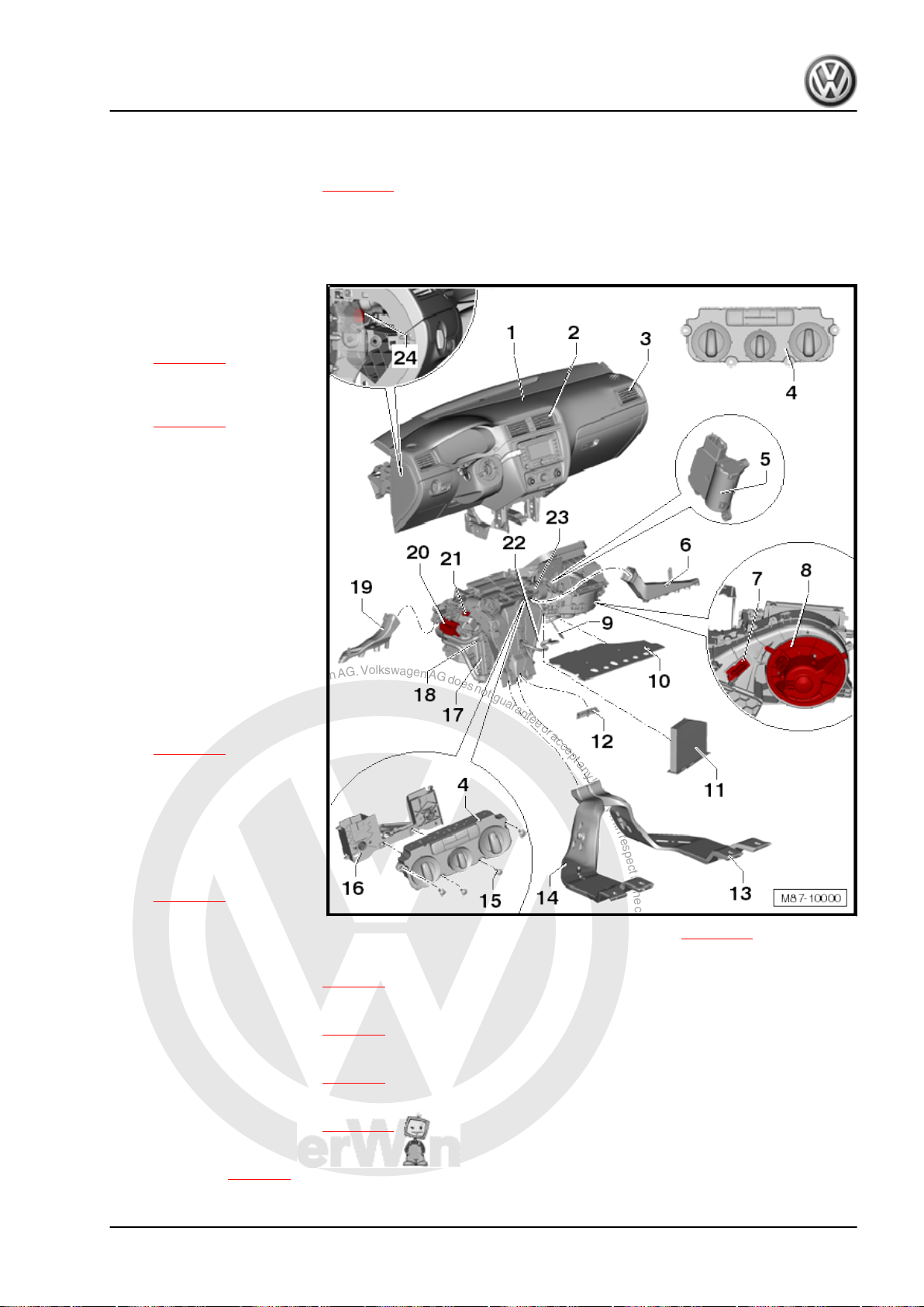
P
r
o
t
e
c
t
e
d
b
y
c
o
p
y
r
i
g
h
t
.
C
o
p
y
i
n
g
f
o
r
p
r
i
v
a
t
e
o
r
c
o
m
m
e
r
c
i
a
l
p
u
r
p
o
s
e
s
,
i
n
p
a
r
t
o
r
i
n
w
h
o
l
e
,
i
s
n
o
t
p
e
r
m
i
t
t
e
d
u
n
l
e
s
s
a
u
t
h
o
r
i
s
e
d
b
y
V
o
l
k
s
w
a
g
e
n
A
G
.
V
o
l
k
s
w
a
g
e
n
A
G
d
o
e
s
n
o
t
g
u
a
r
a
n
t
e
e
o
r
a
c
c
e
p
t
a
n
y
l
i
a
b
i
l
i
t
y
w
i
t
h
r
e
s
p
e
c
t
t
o
t
h
e
c
o
r
r
e
c
t
n
e
s
s
o
f
i
n
f
o
r
m
a
t
i
o
n
i
n
t
h
i
s
d
o
c
u
m
e
n
t
.
C
o
p
y
r
i
g
h
t
b
y
V
o
l
k
s
w
a
g
e
n
A
G
.
Golf Variant 2007 ➤ , Golf Variant 2010 ➤ , Jetta 2005 ➤ , Jetta 2011 ➤
Heating, air conditioning - Edition 04.2010
26 - Left side vent
27 - Centre vent temperature sender -G191-
❑ Removing and installing ⇒ page 54
2.2 Air conditioning system and heater - passenger compartment (Jetta 2011►)
1 - Dash panel
2 - Centre vents
❑ Removing and installing
⇒ page 10
3 - Right vent
❑ Removing and installing
⇒ page 12
4 - Heating and air conditioning
controls, Climatic
❑ With fresh air and air re‐
circulation flap switch E159- .
❑ With heated rear win‐
dow button -E230- .
❑ With fresh air blower
switch -E9-
❑ With air conditioning
system control unit J301- .
❑ For vehicles with sup‐
plementary heating hav‐
ing instant heating but‐
ton -E537- .
❑ Removing and installing
⇒ page 48
5 - Air recirculation flap control
motor -V113-
❑ Checking: vehicle diag‐
❑ Removing and installing
❑ Renewing: initiate basic
6 - Right footwell vent
❑ Removing and installing ⇒ page 9
7 - Fresh air blower series resistor with overheating fuse -N24-
❑ Removing and installing ⇒ page 6
8 - Fresh air blower -V2-
❑ Removing and installing ⇒ page 5
nosis, testing and infor‐
mation system -VAS
5051B- .
⇒ page 51
setting using vehicle diagnosis, testing and information system -VAS 5051B- ⇒ page 55 .
9 - Flexible shaft
❑ Removing and installing ⇒ page 50 .
10 - Baffle plate for heater unit
❑ Removing ⇒ page 3
2. Air conditioning system with manual controls, Climatic 41
Page 48

P
r
o
t
e
c
t
e
d
b
y
c
o
p
y
r
i
g
h
t
.
C
o
p
y
i
n
g
f
o
r
p
r
i
v
a
t
e
o
r
c
o
m
m
e
r
c
i
a
l
p
u
r
p
o
s
e
s
,
i
n
p
a
r
t
o
r
i
n
w
h
o
l
e
,
i
s
n
o
t
p
e
r
m
i
t
t
e
d
u
n
l
e
s
s
a
u
t
h
o
r
i
s
e
d
b
y
V
o
l
k
s
w
a
g
e
n
A
G
.
V
o
l
k
s
w
a
g
e
n
A
G
d
o
e
s
n
o
t
g
u
a
r
a
n
t
e
e
o
r
a
c
c
e
p
t
a
n
y
l
i
a
b
i
l
i
t
y
w
i
t
h
r
e
s
p
e
c
t
t
o
t
h
e
c
o
r
r
e
c
t
n
e
s
s
o
f
i
n
f
o
r
m
a
t
i
o
n
i
n
t
h
i
s
d
o
c
u
m
e
n
t
.
C
o
p
y
r
i
g
h
t
b
y
V
o
l
k
s
w
a
g
e
n
A
G
.
Golf Variant 2007 ➤ , Golf Variant 2010 ➤ , Jetta 2005 ➤ , Jetta 2011 ➤
Heating, air conditioning - Edition 04.2010
11 - Dust and pollen filter
❑ With activated charcoal filter
❑ Removing and installing ⇒ page 6
12 - Sealing cap
❑ Fitted only in vehicles without air duct to vent in rear centre console.
13 - Air duct for right rear footwell
❑ Removing and installing ⇒ page 8
14 - Air duct for left rear footwell
❑ Removing and installing ⇒ page 8
15 - Securing bolt
❑ Qty. 8
16 - Adapter for controls
17 - Auxiliary air heater element -Z35-
❑ Only in vehicles with diesel engines without auxiliary coolant heater.
❑ Removing and installing ⇒ page 26
18 - Heat exchanger
❑ Removing and installing ⇒ page 23
❑ After renewing heat exchanger, renew coolant completely ⇒ Rep. gr. 19 .
19 - Left footwell vent
❑ Removing and installing ⇒ page 9
20 - Temperature flap control motor -V68-
❑ Checking: vehicle diagnosis, testing and information system -VAS 5051B- .
❑ Removing and installing ⇒ page 51
❑ Renewing: initiate basic setting using vehicle diagnosis, testing and information system -VAS 5051B-
⇒ page 55 .
21 - Footwell vent temperature sender -G192-
❑ Removing and installing ⇒ page 53
22 - Evaporator temperature sensor -G308-
❑ Removing and installing ⇒ page 77
23 - Heater and air conditioning unit
❑ Removing and installing ⇒ page 42
❑ Dismantling and assembling ⇒ page 47
24 - Centre vent temperature sender -G191-
❑ Removing and installing ⇒ page 54
2.3 Removing and installing heater and air conditioner unit (Climatic)
Special tools and workshop equipment required
42 Rep. gr.87 - Air conditioning system
Page 49
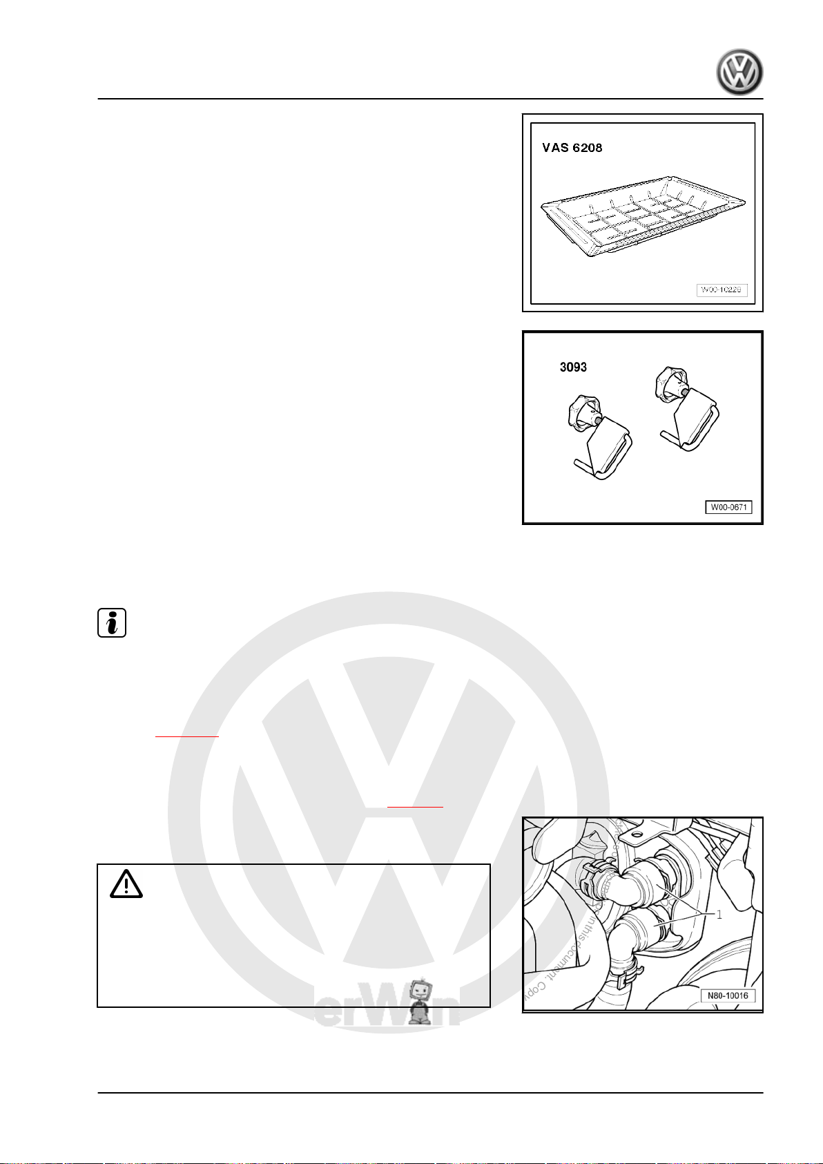
P
r
o
t
e
c
t
e
d
b
y
c
o
p
y
r
i
g
h
t
.
C
o
p
y
i
n
g
f
o
r
p
r
i
v
a
t
e
o
r
c
o
m
m
e
r
c
i
a
l
p
u
r
p
o
s
e
s
,
i
n
p
a
r
t
o
r
i
n
w
h
o
l
e
,
i
s
n
o
t
p
e
r
m
i
t
t
e
d
u
n
l
e
s
s
a
u
t
h
o
r
i
s
e
d
b
y
V
o
l
k
s
w
a
g
e
n
A
G
.
V
o
l
k
s
w
a
g
e
n
A
G
d
o
e
s
n
o
t
g
u
a
r
a
n
t
e
e
o
r
a
c
c
e
p
t
a
n
y
l
i
a
b
i
l
i
t
y
w
i
t
h
r
e
s
p
e
c
t
t
o
t
h
e
c
o
r
r
e
c
t
n
e
s
s
o
f
i
n
f
o
r
m
a
t
i
o
n
i
n
t
h
i
s
d
o
c
u
m
e
n
t
.
C
o
p
y
r
i
g
h
t
b
y
V
o
l
k
s
w
a
g
e
n
A
G
.
Golf Variant 2007 ➤ , Golf Variant 2010 ➤ , Jetta 2005 ➤ , Jetta 2011 ➤
♦ Drip tray for workshop hoist -VAS 6208-
♦ Hose clamps up to 40 mm Ø -VAS 3093-
Heating, air conditioning - Edition 04.2010
♦ Compressed air gun, commercially available
2.3.1 Removing
Note
To improve access, depending on engine version, additional com‐
ponents, e.g. engine cover must be removed ⇒ Rep. gr. 10 .
– Extract refrigerant, e.g. with air conditioner service station -
VAS 6007A- before opening refrigerant circuit. Comply with
notes ⇒ page 38 .
– Remove dash panel ⇒ Rep. gr. 70 .
– Remove bulkhead in plenum chamber ⇒ Rep. gr. 50 .
– Remove left and right rear footwell air ducts ⇒ page 8 .
– Place drip tray -VAS 6208- beneath engine.
– Mark coolant hoses -1-.
WARNING
Danger of scalding injuries.
When the engine is warm, the coolant temperature may be
above 100 °C. The cooling system is pressurised.
If necessary, release pressure and reduce temperature before
carrying out repairs.
2. Air conditioning system with manual controls, Climatic 43
Page 50
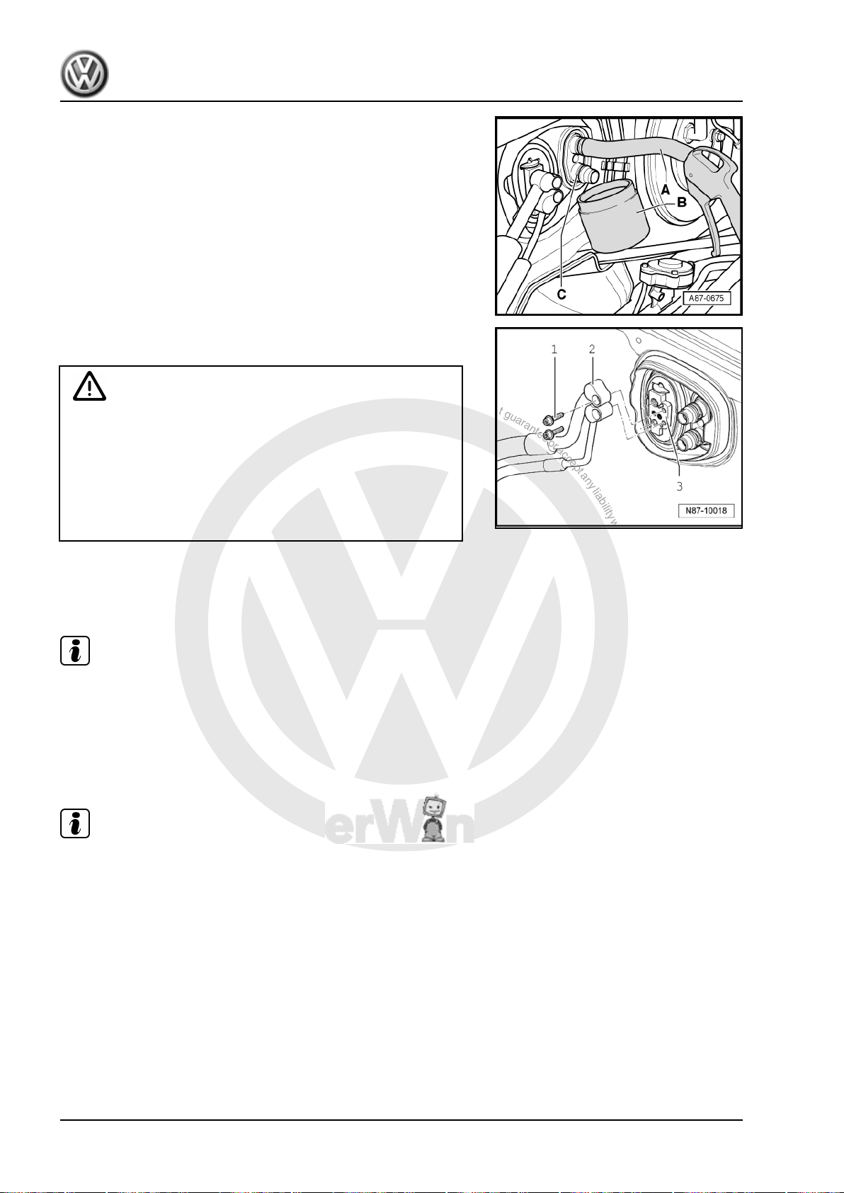
P
r
o
t
e
c
t
e
d
b
y
c
o
p
y
r
i
g
h
t
.
C
o
p
y
i
n
g
f
o
r
p
r
i
v
a
t
e
o
r
c
o
m
m
e
r
c
i
a
l
p
u
r
p
o
s
e
s
,
i
n
p
a
r
t
o
r
i
n
w
h
o
l
e
,
i
s
n
o
t
p
e
r
m
i
t
t
e
d
u
n
l
e
s
s
a
u
t
h
o
r
i
s
e
d
b
y
V
o
l
k
s
w
a
g
e
n
A
G
.
V
o
l
k
s
w
a
g
e
n
A
G
d
o
e
s
n
o
t
g
u
a
r
a
n
t
e
e
o
r
a
c
c
e
p
t
a
n
y
l
i
a
b
i
l
i
t
y
w
i
t
h
r
e
s
p
e
c
t
t
o
t
h
e
c
o
r
r
e
c
t
n
e
s
s
o
f
i
n
f
o
r
m
a
t
i
o
n
i
n
t
h
i
s
d
o
c
u
m
e
n
t
.
C
o
p
y
r
i
g
h
t
b
y
V
o
l
k
s
w
a
g
e
n
A
G
.
Golf Variant 2007 ➤ , Golf Variant 2010 ➤ , Jetta 2005 ➤ , Jetta 2011 ➤
Heating, air conditioning - Edition 04.2010
– Clamp off coolant hoses -1- with hose clamps up to 40 mm Ø
-VAS 3093- and disconnect coolant hoses to heat exchanger.
– Push a piece of hose -A- onto upper union.
– Hold a container -B- under lower connection -C-.
– Carefully blow remaining coolant out through unions of heat
exchanger using a compressed air pistol.
WARNING
Danger of freezing injuries.
If refrigerant circuit has not been evacuated, refrigerant will
escape.
Extract refrigerant before opening refrigerant circuit. If the re‐
frigerant circuit is not opened within 10 minutes after it has
been evacuated, pressure may develop in coolant circuit due
to re-evaporation. Extract refrigerant again.
– From engine compartment, undo bolts (12 Nm) -1- for refrig‐
erant lines -2-.
– Take refrigerant lines out of expansion valve -3-.
Note
♦
Seal open connections for lines.
♦
To seal open connections of expansion valve, use, for exam‐
ple, sealing cap of a spare expansion valve.
– Cover carpet in interior of vehicle with a waterproof foil and
water absorbing paper.
Note
During removal, note lengths and locations of bolts for later installation.
44 Rep. gr.87 - Air conditioning system
Page 51
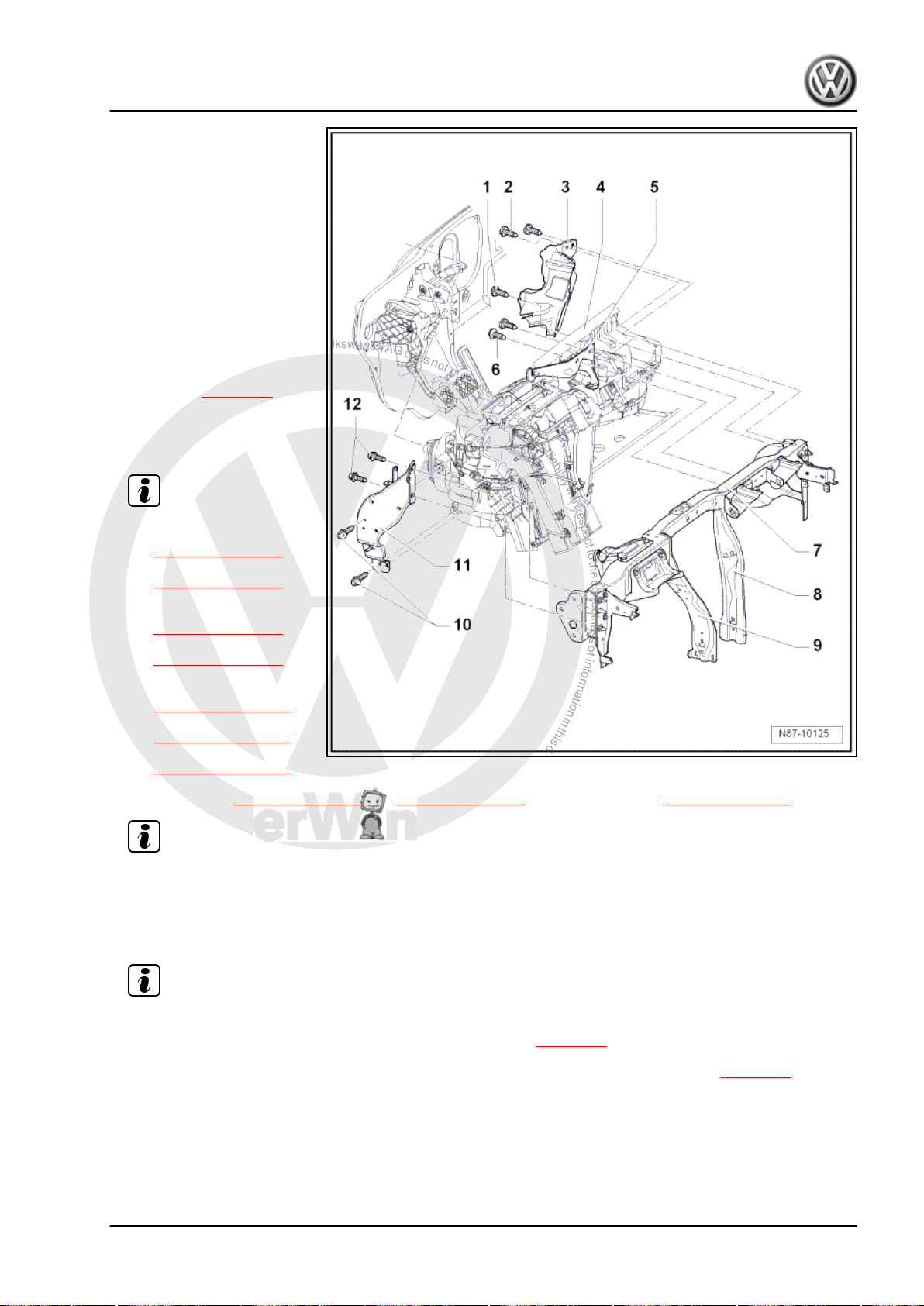
P
r
o
t
e
c
t
e
d
b
y
c
o
p
y
r
i
g
h
t
.
C
o
p
y
i
n
g
f
o
r
p
r
i
v
a
t
e
o
r
c
o
m
m
e
r
c
i
a
l
p
u
r
p
o
s
e
s
,
i
n
p
a
r
t
o
r
i
n
w
h
o
l
e
,
i
s
n
o
t
p
e
r
m
i
t
t
e
d
u
n
l
e
s
s
a
u
t
h
o
r
i
s
e
d
b
y
V
o
l
k
s
w
a
g
e
n
A
G
.
V
o
l
k
s
w
a
g
e
n
A
G
d
o
e
s
n
o
t
g
u
a
r
a
n
t
e
e
o
r
a
c
c
e
p
t
a
n
y
l
i
a
b
i
l
i
t
y
w
i
t
h
r
e
s
p
e
c
t
t
o
t
h
e
c
o
r
r
e
c
t
n
e
s
s
o
f
i
n
f
o
r
m
a
t
i
o
n
i
n
t
h
i
s
d
o
c
u
m
e
n
t
.
C
o
p
y
r
i
g
h
t
b
y
V
o
l
k
s
w
a
g
e
n
A
G
.
Golf Variant 2007 ➤ , Golf Variant 2010 ➤ , Jetta 2005 ➤ , Jetta 2011 ➤
Heating, air conditioning - Edition 04.2010
1 - Bolt
❑ 4 Nm
2 - Bolts
❑ Qty. 2
❑ 4 Nm
3 - Cable retainer
4 - Heater and air conditioning
unit
❑ Removing:
– Take condensation wa‐
ter drainage hose off
Note
heater and air condition‐
er unit ⇒ page 79 .
– Disconnect connectors
from heater and air con‐
ditioner unit.
– Undo bolts
⇒ Item 6 (page 45)
from bracket
⇒ Item 5 (page 45) .
– Remove supports
⇒ Item 8 (page 46)
and
⇒ Item 9 (page 46) .
– Remove bolts
⇒ Item 10 (page 46)
and
⇒ Item 12 (page 46)
and remove bracket
⇒ Item 11 (page 46) .
– Undo bolts ⇒ Item 2 (page 45) and ⇒ Item 1 (page 45) from cable retainer ⇒ Item 3 (page 45) .
Note
– Remove heater and air conditioning unit.
Installing:
Install in reverse order. Note the following when doing this:
Note
– Second mechanic must guide both coolant pipes though seal in engine compartment, from engine com‐
partment, to heat exchanger when installing heater unit ⇒ page 46 .
– When installing, ensure that condensation water drainage hose is correctly seated ⇒ page 79 .
– Fill with coolant ⇒ Rep. gr. 19 .
5 - Bracket
6 - Bolts
❑ 8 Nm
2. Air conditioning system with manual controls, Climatic 45
Page 52
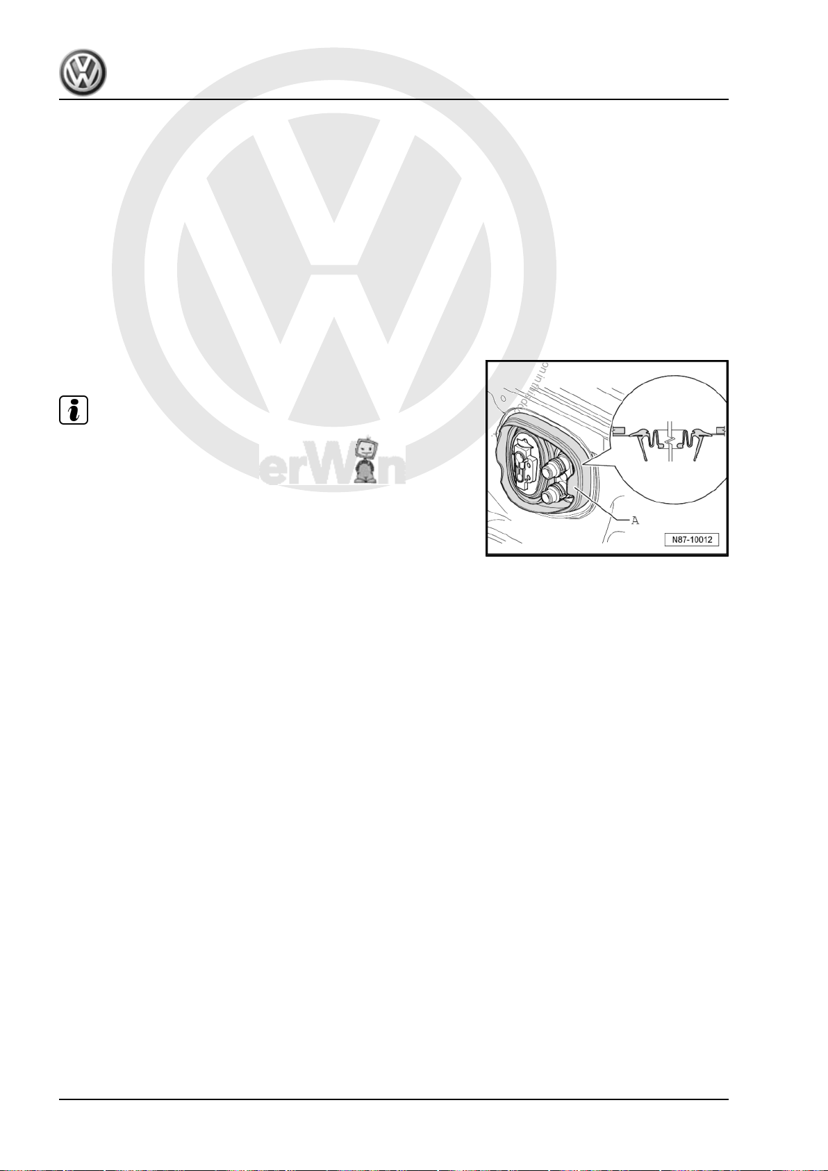
P
r
o
t
e
c
t
e
d
b
y
c
o
p
y
r
i
g
h
t
.
C
o
p
y
i
n
g
f
o
r
p
r
i
v
a
t
e
o
r
c
o
m
m
e
r
c
i
a
l
p
u
r
p
o
s
e
s
,
i
n
p
a
r
t
o
r
i
n
w
h
o
l
e
,
i
s
n
o
t
p
e
r
m
i
t
t
e
d
u
n
l
e
s
s
a
u
t
h
o
r
i
s
e
d
b
y
V
o
l
k
s
w
a
g
e
n
A
G
.
V
o
l
k
s
w
a
g
e
n
A
G
d
o
e
s
n
o
t
g
u
a
r
a
n
t
e
e
o
r
a
c
c
e
p
t
a
n
y
l
i
a
b
i
l
i
t
y
w
i
t
h
r
e
s
p
e
c
t
t
o
t
h
e
c
o
r
r
e
c
t
n
e
s
s
o
f
i
n
f
o
r
m
a
t
i
o
n
i
n
t
h
i
s
d
o
c
u
m
e
n
t
.
C
o
p
y
r
i
g
h
t
b
y
V
o
l
k
s
w
a
g
e
n
A
G
.
Golf Variant 2007 ➤ , Golf Variant 2010 ➤ , Jetta 2005 ➤ , Jetta 2011 ➤
Heating, air conditioning - Edition 04.2010
7 - Assembly carrier
8 - Right support
9 - Left support
10 - Bolts
❑ Qty. 2
❑ 8 Nm
11 - Bracket
12 - Bolts
❑ Qty. 2
❑ 8 Nm
Heater and air conditioning unit/engine compartment seal
Note
Observe position of seal -A- during installation.
46 Rep. gr.87 - Air conditioning system
Page 53
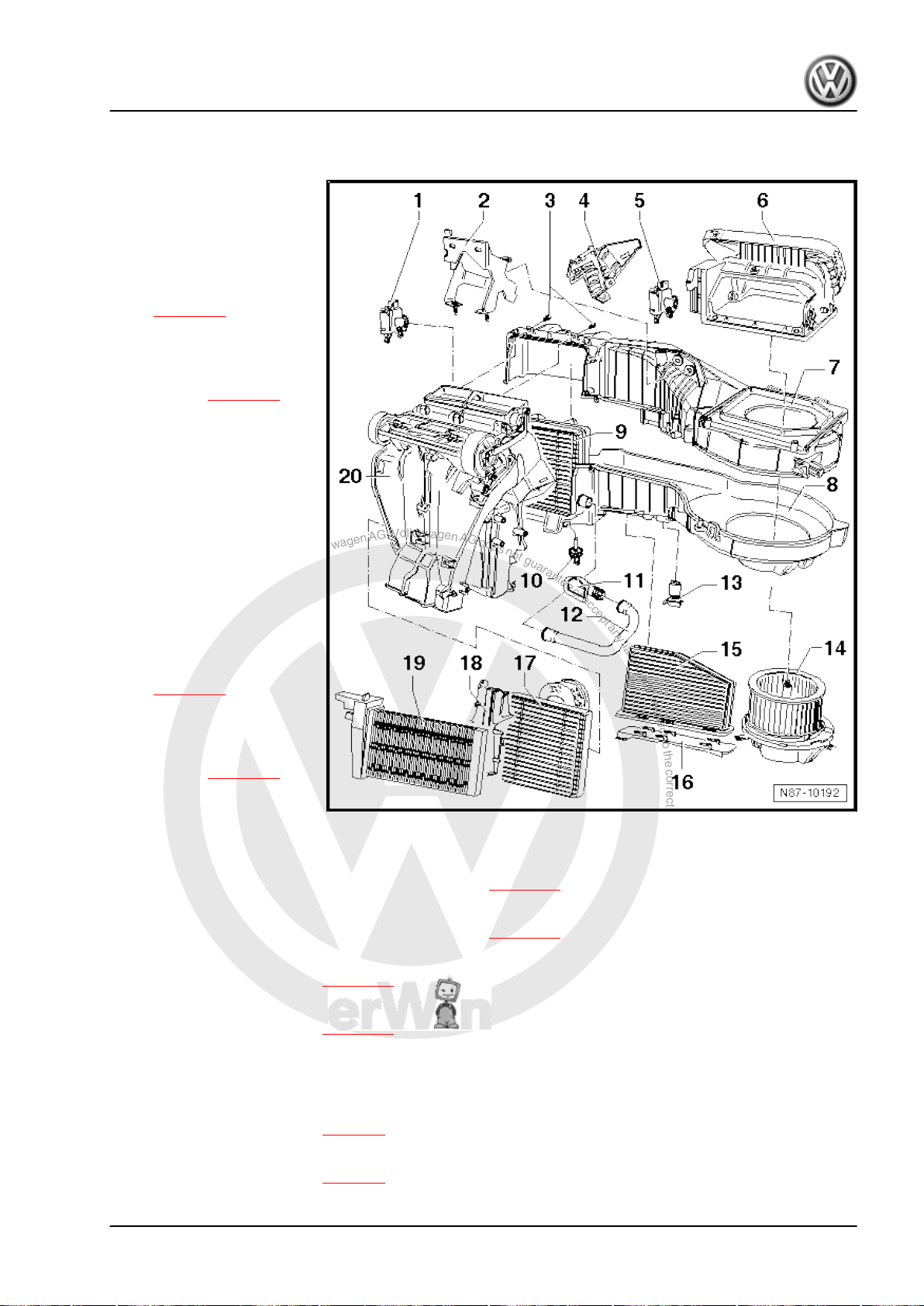
P
r
o
t
e
c
t
e
d
b
y
c
o
p
y
r
i
g
h
t
.
C
o
p
y
i
n
g
f
o
r
p
r
i
v
a
t
e
o
r
c
o
m
m
e
r
c
i
a
l
p
u
r
p
o
s
e
s
,
i
n
p
a
r
t
o
r
i
n
w
h
o
l
e
,
i
s
n
o
t
p
e
r
m
i
t
t
e
d
u
n
l
e
s
s
a
u
t
h
o
r
i
s
e
d
b
y
V
o
l
k
s
w
a
g
e
n
A
G
.
V
o
l
k
s
w
a
g
e
n
A
G
d
o
e
s
n
o
t
g
u
a
r
a
n
t
e
e
o
r
a
c
c
e
p
t
a
n
y
l
i
a
b
i
l
i
t
y
w
i
t
h
r
e
s
p
e
c
t
t
o
t
h
e
c
o
r
r
e
c
t
n
e
s
s
o
f
i
n
f
o
r
m
a
t
i
o
n
i
n
t
h
i
s
d
o
c
u
m
e
n
t
.
C
o
p
y
r
i
g
h
t
b
y
V
o
l
k
s
w
a
g
e
n
A
G
.
Golf Variant 2007 ➤ , Golf Variant 2010 ➤ , Jetta 2005 ➤ , Jetta 2011 ➤
Heating, air conditioning - Edition 04.2010
2.4 Dismantling and assembling heater and air conditioning unit (Climatic)
1 - Temperature flap control
motor -V68-
❑ Checking: vehicle diag‐
nosis, testing and infor‐
mation system -VAS
5051B- .
❑ Removing and installing
⇒ page 51
❑ Renewing: initiate basic
setting using vehicle di‐
agnosis, testing and in‐
formation system -VAS
5051B- ⇒ page 55 .
2 - Bracket
3 - Bolts
❑ Bolts must be removed
to separate air distribu‐
tion housing from evap‐
orator housing.
4 - Cover
5 - Air recirculation flap control
motor -V113-
❑ Checking: vehicle diag‐
nosis, testing and infor‐
mation system -VAS
5051B- .
❑ Removing and installing
❑ Renewing: initiate basic
6 - Air intake housing
❑ With air recirculation
7 - Evaporator housing - upper part
❑ Dismantling and assembling evaporator housing ⇒ page 75
8 - Evaporator housing - lower part
⇒ page 51
setting using vehicle di‐
agnosis, testing and in‐
formation system -VAS
5051B- ⇒ page 55 .
flap
❑ Dismantling and assembling evaporator housing ⇒ page 75
9 - Evaporator
❑ Removing and installing ⇒ page 99
10 - Evaporator temperature sensor -G308-
❑ Removing and installing ⇒ page 77
11 - Connection for glove compartment cooling
12 - Cooling hose for glove compartment
13 - Fresh air blower series resistor with overheating fuse -N24-
❑ Removing and installing ⇒ page 6
14 - Fresh air blower -V2-
❑ Removing and installing ⇒ page 5
2. Air conditioning system with manual controls, Climatic 47
Page 54
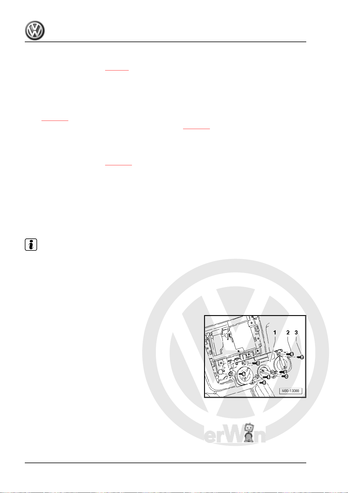
P
r
o
t
e
c
t
e
d
b
y
c
o
p
y
r
i
g
h
t
.
C
o
p
y
i
n
g
f
o
r
p
r
i
v
a
t
e
o
r
c
o
m
m
e
r
c
i
a
l
p
u
r
p
o
s
e
s
,
i
n
p
a
r
t
o
r
i
n
w
h
o
l
e
,
i
s
n
o
t
p
e
r
m
i
t
t
e
d
u
n
l
e
s
s
a
u
t
h
o
r
i
s
e
d
b
y
V
o
l
k
s
w
a
g
e
n
A
G
.
V
o
l
k
s
w
a
g
e
n
A
G
d
o
e
s
n
o
t
g
u
a
r
a
n
t
e
e
o
r
a
c
c
e
p
t
a
n
y
l
i
a
b
i
l
i
t
y
w
i
t
h
r
e
s
p
e
c
t
t
o
t
h
e
c
o
r
r
e
c
t
n
e
s
s
o
f
i
n
f
o
r
m
a
t
i
o
n
i
n
t
h
i
s
d
o
c
u
m
e
n
t
.
C
o
p
y
r
i
g
h
t
b
y
V
o
l
k
s
w
a
g
e
n
A
G
.
Golf Variant 2007 ➤ , Golf Variant 2010 ➤ , Jetta 2005 ➤ , Jetta 2011 ➤
Heating, air conditioning - Edition 04.2010
15 - Dust and pollen filter
❑ With activated charcoal filter
❑ Removing and installing ⇒ page 6
16 - Cover
❑ For dust and pollen filter.
17 - Heat exchanger
❑ After renewing heat exchanger, renew coolant completely ⇒ Rep. gr. 19 .
❑ Removing and installing heat exchanger (Golf Variant 2007►, Golf Variant 2010► und Jetta 2005►)
⇒ page 19 .
❑ Removing and installing heat exchanger (Jetta 2010►) ⇒ page 23 .
18 - Heat exchanger cladding
19 - Auxiliary air heater element -Z35-
❑ Only in vehicles with diesel engines without supplementary heater.
❑ Removing and installing ⇒ page 26
20 - Air distribution housing
2.5 Removing and installing heating and air conditioning controls, Climatic
2.5.1 Removing
Note
♦
The control consists of 2 separable housings. Before removing
controls, set rotary knobs to the following positions:
♦
Heater control to „cold“
♦
Blower to „0“
♦
Vent direction to „footwell“
– Remove radio ⇒ Rep. gr. 91 .
– Models with no radio trim, removing centre part of dash panel .
⇒ Rep. gr. 68
48 Rep. gr.87 - Air conditioning system
Page 55
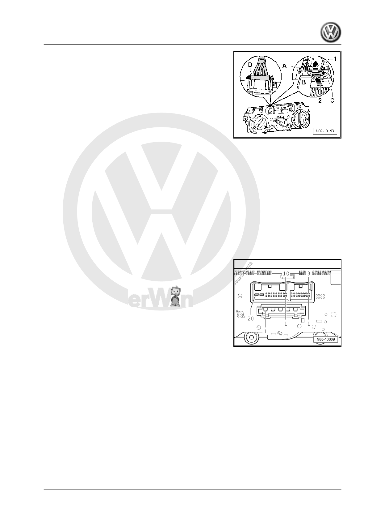
P
r
o
t
e
c
t
e
d
b
y
c
o
p
y
r
i
g
h
t
.
C
o
p
y
i
n
g
f
o
r
p
r
i
v
a
t
e
o
r
c
o
m
m
e
r
c
i
a
l
p
u
r
p
o
s
e
s
,
i
n
p
a
r
t
o
r
i
n
w
h
o
l
e
,
i
s
n
o
t
p
e
r
m
i
t
t
e
d
u
n
l
e
s
s
a
u
t
h
o
r
i
s
e
d
b
y
V
o
l
k
s
w
a
g
e
n
A
G
.
V
o
l
k
s
w
a
g
e
n
A
G
d
o
e
s
n
o
t
g
u
a
r
a
n
t
e
e
o
r
a
c
c
e
p
t
a
n
y
l
i
a
b
i
l
i
t
y
w
i
t
h
r
e
s
p
e
c
t
t
o
t
h
e
c
o
r
r
e
c
t
n
e
s
s
o
f
i
n
f
o
r
m
a
t
i
o
n
i
n
t
h
i
s
d
o
c
u
m
e
n
t
.
C
o
p
y
r
i
g
h
t
b
y
V
o
l
k
s
w
a
g
e
n
A
G
.
Golf Variant 2007 ➤ , Golf Variant 2010 ➤ , Jetta 2005 ➤ , Jetta 2011 ➤
Heating, air conditioning - Edition 04.2010
– Remove bolts -2- (4.2 x 45) and -3- (4.2 x 16) and remove the
controls -1- from centre console.
– Release connector catch -A- by pulling it in direction of arrow
-1-.
– Push connector catch -B- towards connector -arrow 2- and
remove connector -C-.
– Release connector catch -D- and remove connector -D-.
2.5.2 Installing
Install in reverse order. Note: the rotating knobs must be in the
same position as when removed.
2.6 Connections on controls for heating and
2.6.1 Pin assignment for multi-pin connectors
Special tools and workshop equipment required
♦ Test adapter -V.A.G 1598/47-
20-pin connector, T20c in current flow diagram
3 - Centre vent temperature sender -G191-
5 - High-pressure sender -G65-
7 - CAN, low
8 - CAN, high
air conditioning, Climatic
on back of controls for heating and air
conditioning, Climatic
12 - Right seat heating (optional)
13 - Left seat heating (optional)
15 - Terminal 75, seat heating (optional)
16 - Air conditioning system compressor regulating valve -N280-
19 - Terminal 30A
20 - Terminal 31
2. Air conditioning system with manual controls, Climatic 49
Page 56
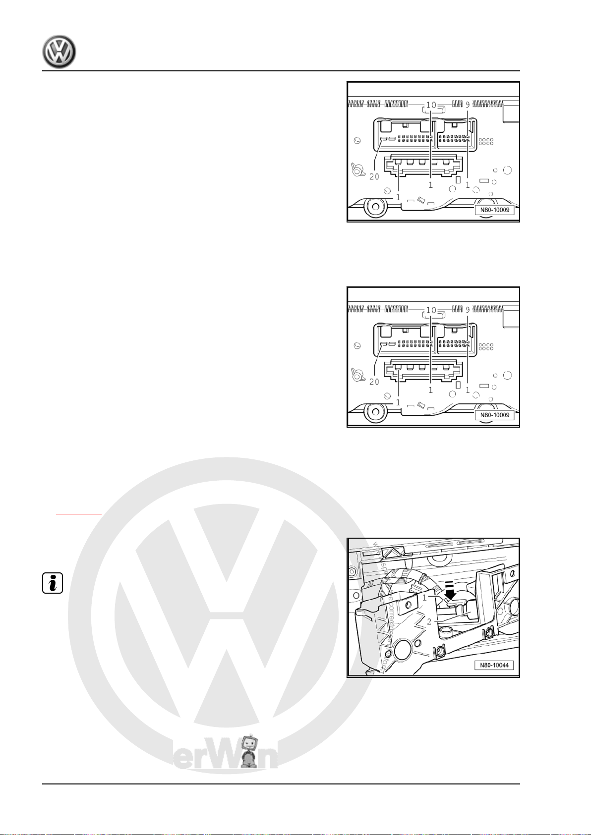
P
r
o
t
e
c
t
e
d
b
y
c
o
p
y
r
i
g
h
t
.
C
o
p
y
i
n
g
f
o
r
p
r
i
v
a
t
e
o
r
c
o
m
m
e
r
c
i
a
l
p
u
r
p
o
s
e
s
,
i
n
p
a
r
t
o
r
i
n
w
h
o
l
e
,
i
s
n
o
t
p
e
r
m
i
t
t
e
d
u
n
l
e
s
s
a
u
t
h
o
r
i
s
e
d
b
y
V
o
l
k
s
w
a
g
e
n
A
G
.
V
o
l
k
s
w
a
g
e
n
A
G
d
o
e
s
n
o
t
g
u
a
r
a
n
t
e
e
o
r
a
c
c
e
p
t
a
n
y
l
i
a
b
i
l
i
t
y
w
i
t
h
r
e
s
p
e
c
t
t
o
t
h
e
c
o
r
r
e
c
t
n
e
s
s
o
f
i
n
f
o
r
m
a
t
i
o
n
i
n
t
h
i
s
d
o
c
u
m
e
n
t
.
C
o
p
y
r
i
g
h
t
b
y
V
o
l
k
s
w
a
g
e
n
A
G
.
Golf Variant 2007 ➤ , Golf Variant 2010 ➤ , Jetta 2005 ➤ , Jetta 2011 ➤
Heating, air conditioning - Edition 04.2010
16-pin connector, T16e in current flow diagram
1 - Temperature flap control motor -V68- , warm
2 - Evaporator output temperature sender -G263-
4 - Footwell vent temperature sender -G192-
5 - Temperature flap control motor potentiometer -G92-
7 - + 5 V for temperature flap control motor potentiometer -G92-
8 - Ground for temperature flap control motor potentiometer G92- , centre vent temperature sender -G191- , footwell vent
temperature sender -G192- and evaporator output temperature
sensor -G263-
9 - Air recirculation flap control motor -V113- , open
10 - Air recirculation flap control motor -V113- , closed
11 - Temperature flap control motor -V68- , cold
5-pin connector, T5 in current flow diagram
1 - Blower 3rd speed
2 - Blower 2nd speed
3 - Blower 1st speed
4 - Bower 4th speed
5 - X terminal
2.7 Removing and installing flexible shaft
2.7.1 Removing
– Remove heating and air conditioning controls, Climatic
⇒ page 48 .
– Carefully pull out adapter for controls.
– Press in locking lug -arrow- of flexible shaft and pull out flexible
shaft.
Note
When flexible shaft is installed, the adapter and the rotary knobs
of the controls for heater and air conditioning system (Climatic)
must be aligned in a specific position to one another. Otherwise
the system will malfunction.
2.7.2 Checking
Flexible shaft for air distribution flap actuator:
– Run fresh air blower at highest speed. If air flows out of de‐
froster vent in the „defrost“ position, and no air flows out of
footwell vent, then the flexible shaft is correctly installed. Oth‐
erwise, remove flexible shaft from adapter. Position controls
for Climatic heating and air conditioning system on adapter
50 Rep. gr.87 - Air conditioning system
Page 57
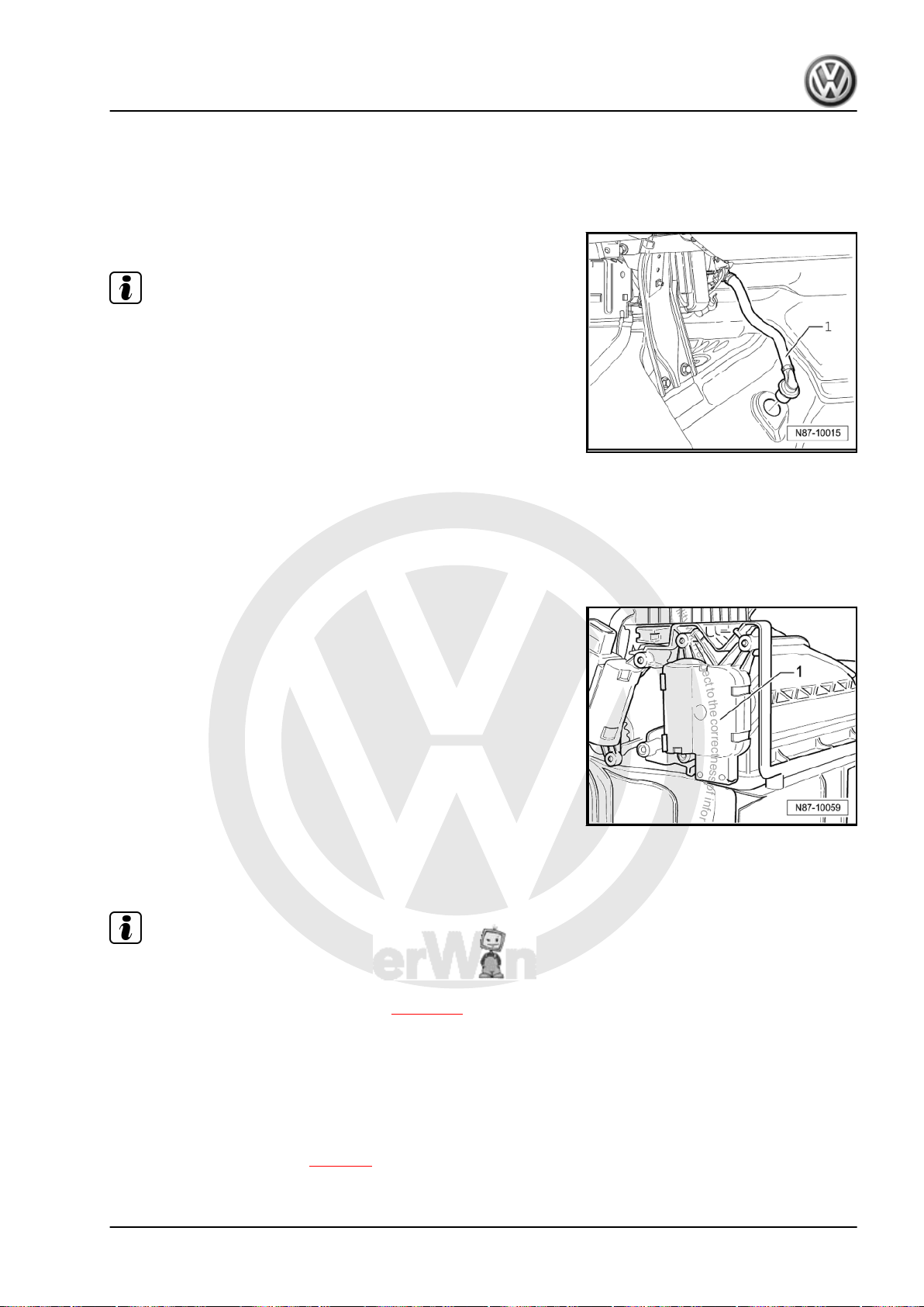
P
r
o
t
e
c
t
e
d
b
y
c
o
p
y
r
i
g
h
t
.
C
o
p
y
i
n
g
f
o
r
p
r
i
v
a
t
e
o
r
c
o
m
m
e
r
c
i
a
l
p
u
r
p
o
s
e
s
,
i
n
p
a
r
t
o
r
i
n
w
h
o
l
e
,
i
s
n
o
t
p
e
r
m
i
t
t
e
d
u
n
l
e
s
s
a
u
t
h
o
r
i
s
e
d
b
y
V
o
l
k
s
w
a
g
e
n
A
G
.
V
o
l
k
s
w
a
g
e
n
A
G
d
o
e
s
n
o
t
g
u
a
r
a
n
t
e
e
o
r
a
c
c
e
p
t
a
n
y
l
i
a
b
i
l
i
t
y
w
i
t
h
r
e
s
p
e
c
t
t
o
t
h
e
c
o
r
r
e
c
t
n
e
s
s
o
f
i
n
f
o
r
m
a
t
i
o
n
i
n
t
h
i
s
d
o
c
u
m
e
n
t
.
C
o
p
y
r
i
g
h
t
b
y
V
o
l
k
s
w
a
g
e
n
A
G
.
Golf Variant 2007 ➤ , Golf Variant 2010 ➤ , Jetta 2005 ➤ , Jetta 2011 ➤
Heating, air conditioning - Edition 04.2010
and turn rotary knob for air distribution 1/2 turn (180°). Then
reconnect flexible shaft. Repeat check.
2.8 Checking condensation water drainage hose on heater and air conditioner unit
– Remove footwell cover on front passenger side .
Note
♦
It must be possible to push condensation drain hose -1- onto
the heater and air conditioning unit connection without tension.
♦
The condensation drain hose must be fitted securely to the
connection for condensation drainage of the heater and air
conditioner unit.
2.9 Removing and installing air recirculation flap control motor -V113-
2.9.1 Removing
– Remove glove compartment ⇒ Rep. gr. 68 .
– Remove cover for control motors.
– Disconnect connector on air recirculation flap control motor -
V113- -1-.
– Pull off air recirculation flap control motor -V113- -1-.
2.9.2 Installing
Install in reverse order.
Note
♦
After installation, check operation of air recirculation flap.
♦
Initiate „basic setting“ function using vehicle diagnosis, testing
and information system -VAS 5051B- ⇒ page 55 .
2.10 Removing and installing temperature flap control motor -V68-
2.10.1 Removing
– Remove left footwell vent ⇒ page 9 .
– Remove left trim panel in footwell ⇒ Rep. gr. 68 .
2. Air conditioning system with manual controls, Climatic 51
Page 58
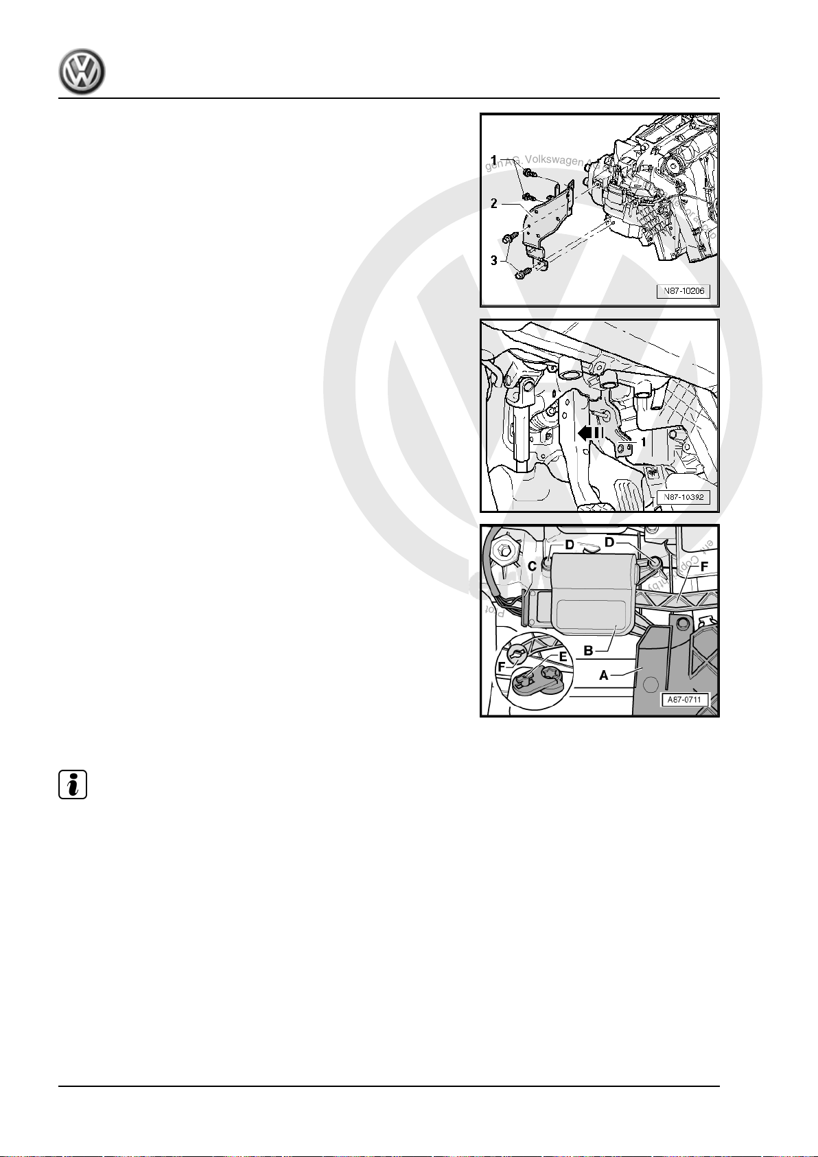
P
r
o
t
e
c
t
e
d
b
y
c
o
p
y
r
i
g
h
t
.
C
o
p
y
i
n
g
f
o
r
p
r
i
v
a
t
e
o
r
c
o
m
m
e
r
c
i
a
l
p
u
r
p
o
s
e
s
,
i
n
p
a
r
t
o
r
i
n
w
h
o
l
e
,
i
s
n
o
t
p
e
r
m
i
t
t
e
d
u
n
l
e
s
s
a
u
t
h
o
r
i
s
e
d
b
y
V
o
l
k
s
w
a
g
e
n
A
G
.
V
o
l
k
s
w
a
g
e
n
A
G
d
o
e
s
n
o
t
g
u
a
r
a
n
t
e
e
o
r
a
c
c
e
p
t
a
n
y
l
i
a
b
i
l
i
t
y
w
i
t
h
r
e
s
p
e
c
t
t
o
t
h
e
c
o
r
r
e
c
t
n
e
s
s
o
f
i
n
f
o
r
m
a
t
i
o
n
i
n
t
h
i
s
d
o
c
u
m
e
n
t
.
C
o
p
y
r
i
g
h
t
b
y
V
o
l
k
s
w
a
g
e
n
A
G
.
Golf Variant 2007 ➤ , Golf Variant 2010 ➤ , Jetta 2005 ➤ , Jetta 2011 ➤
Heating, air conditioning - Edition 04.2010
– Remove data bus diagnosis interface -J533- ⇒ Rep. gr. 97 .
– Remove bolts -3- (9 ± 1.3 Nm).
Do not remove bolts -1-.
– Do not remove bracket -2-.
– Press bracket -1- in direction of brake pedal -arrow- and se‐
cure it there with a cable tie.
– Mark connector -C- to control motor (danger of interchanging
with other connectors of same construction).
– Disconnect connector -C- on temperature flap control motor -
V68- .
– Remove cover -A-.
– Remove securing bolts -D- (1.4 Nm) and remove temperature
flap control motor -V68- -B-.
– Release control motor lever -E- from connecting rod -F-.
2.10.2 Installing
Note
Optimised control motors are marked with an „X“.
To ease assembly, use a ≈ 2 mm shorter oval-head bolt -N 103
254 01- .
52 Rep. gr.87 - Air conditioning system
Page 59
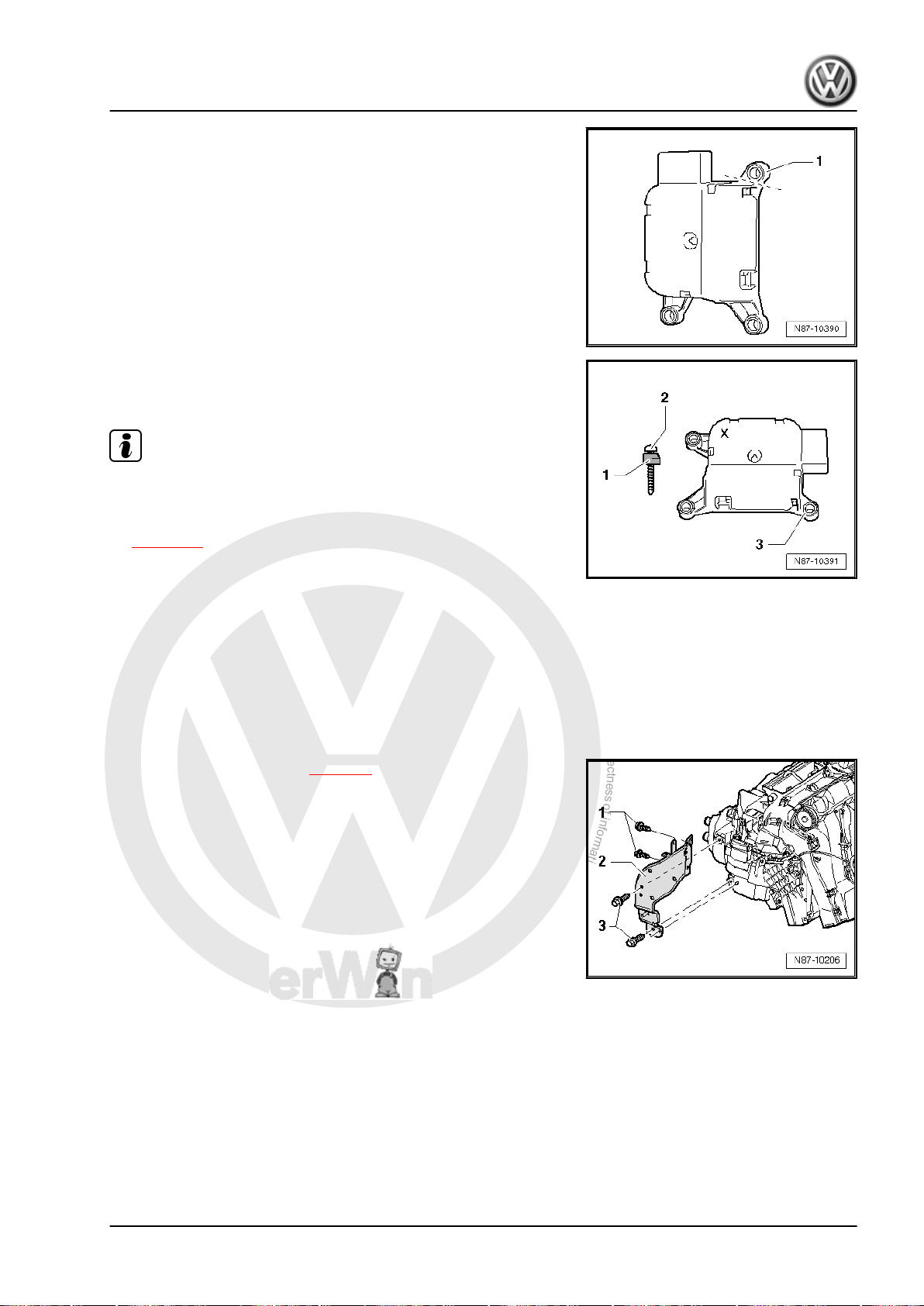
P
r
o
t
e
c
t
e
d
b
y
c
o
p
y
r
i
g
h
t
.
C
o
p
y
i
n
g
f
o
r
p
r
i
v
a
t
e
o
r
c
o
m
m
e
r
c
i
a
l
p
u
r
p
o
s
e
s
,
i
n
p
a
r
t
o
r
i
n
w
h
o
l
e
,
i
s
n
o
t
p
e
r
m
i
t
t
e
d
u
n
l
e
s
s
a
u
t
h
o
r
i
s
e
d
b
y
V
o
l
k
s
w
a
g
e
n
A
G
.
V
o
l
k
s
w
a
g
e
n
A
G
d
o
e
s
n
o
t
g
u
a
r
a
n
t
e
e
o
r
a
c
c
e
p
t
a
n
y
l
i
a
b
i
l
i
t
y
w
i
t
h
r
e
s
p
e
c
t
t
o
t
h
e
c
o
r
r
e
c
t
n
e
s
s
o
f
i
n
f
o
r
m
a
t
i
o
n
i
n
t
h
i
s
d
o
c
u
m
e
n
t
.
C
o
p
y
r
i
g
h
t
b
y
V
o
l
k
s
w
a
g
e
n
A
G
.
Golf Variant 2007 ➤ , Golf Variant 2010 ➤ , Jetta 2005 ➤ , Jetta 2011 ➤
Heating, air conditioning - Edition 04.2010
– Separate bracket -1- from old temperature flap control motor
-V68- , e.g. using side cutting pliers.
– Position new temperature flap control motor -V68- , marked
with an „X“, with shortened oval-head screw -2- and cut-off
bracket -1- on bracket -3- on blower box.
Note
♦
After installation, check operation of left temperature flap.
♦
Initiate „basic settings“ function using vehicle diagnosis, test‐
ing and information system -VAS 5051- or successor model
⇒ page 55 .
2.11 Removing and installing footwell vent
2.11.1 Removing
– Remove dash panel ⇒ Rep. gr. 70 .
– Remove data bus diagnosis interface -J533- ⇒ Rep. gr. 97 .
– Remove left footwell vent ⇒ page 9 .
– Remove bolts -1- and -3- (9 ± 1.3 Nm).
temperature sender -G192-
2. Air conditioning system with manual controls, Climatic 53
Page 60
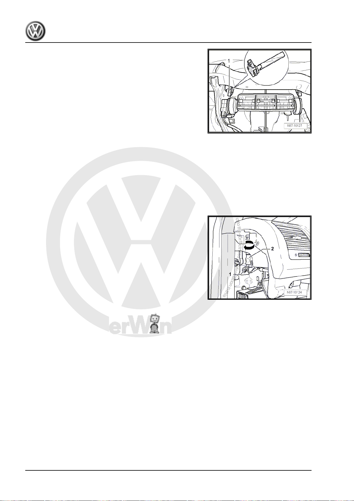
P
r
o
t
e
c
t
e
d
b
y
c
o
p
y
r
i
g
h
t
.
C
o
p
y
i
n
g
f
o
r
p
r
i
v
a
t
e
o
r
c
o
m
m
e
r
c
i
a
l
p
u
r
p
o
s
e
s
,
i
n
p
a
r
t
o
r
i
n
w
h
o
l
e
,
i
s
n
o
t
p
e
r
m
i
t
t
e
d
u
n
l
e
s
s
a
u
t
h
o
r
i
s
e
d
b
y
V
o
l
k
s
w
a
g
e
n
A
G
.
V
o
l
k
s
w
a
g
e
n
A
G
d
o
e
s
n
o
t
g
u
a
r
a
n
t
e
e
o
r
a
c
c
e
p
t
a
n
y
l
i
a
b
i
l
i
t
y
w
i
t
h
r
e
s
p
e
c
t
t
o
t
h
e
c
o
r
r
e
c
t
n
e
s
s
o
f
i
n
f
o
r
m
a
t
i
o
n
i
n
t
h
i
s
d
o
c
u
m
e
n
t
.
C
o
p
y
r
i
g
h
t
b
y
V
o
l
k
s
w
a
g
e
n
A
G
.
Golf Variant 2007 ➤ , Golf Variant 2010 ➤ , Jetta 2005 ➤ , Jetta 2011 ➤
Heating, air conditioning - Edition 04.2010
– Remove bracket -2-.
– Pull connector off footwell vent temperature sender -G192-
-1-.
– Turn footwell vent temperature sender -G192- 90° and remove
it from housing.
2.11.2 Installing
Install in reverse order.
2.12 Removing and installing centre vent
2.12.1 Removing
– Remove cover on left of dash panel ⇒ Rep. gr. 70 .
– Pull connector off centre vent temperature sender -G191-
-1-.
– Turn centre vent temperature sender -G191- -2- 90° in direc‐
tion of -arrow- and remove from dash panel.
2.12.2 Installing
temperature sender -G191-
Install in reverse order.
54 Rep. gr.87 - Air conditioning system
Page 61

P
r
o
t
e
c
t
e
d
b
y
c
o
p
y
r
i
g
h
t
.
C
o
p
y
i
n
g
f
o
r
p
r
i
v
a
t
e
o
r
c
o
m
m
e
r
c
i
a
l
p
u
r
p
o
s
e
s
,
i
n
p
a
r
t
o
r
i
n
w
h
o
l
e
,
i
s
n
o
t
p
e
r
m
i
t
t
e
d
u
n
l
e
s
s
a
u
t
h
o
r
i
s
e
d
b
y
V
o
l
k
s
w
a
g
e
n
A
G
.
V
o
l
k
s
w
a
g
e
n
A
G
d
o
e
s
n
o
t
g
u
a
r
a
n
t
e
e
o
r
a
c
c
e
p
t
a
n
y
l
i
a
b
i
l
i
t
y
w
i
t
h
r
e
s
p
e
c
t
t
o
t
h
e
c
o
r
r
e
c
t
n
e
s
s
o
f
i
n
f
o
r
m
a
t
i
o
n
i
n
t
h
i
s
d
o
c
u
m
e
n
t
.
C
o
p
y
r
i
g
h
t
b
y
V
o
l
k
s
w
a
g
e
n
A
G
.
Golf Variant 2007 ➤ , Golf Variant 2010 ➤ , Jetta 2005 ➤ , Jetta 2011 ➤
Heating, air conditioning - Edition 04.2010
3 Climatronic air conditioning with au‐
tomatic regulation
Note
♦
Pressing the
from automatic operation.
♦
Deviations from automatic operation ⇒ relevant Owner's Man‐
ual.
♦
In „ECON“ operation, only the air conditioner compressor is
switched to almost zero delivery. The heating and ventilation
operations continue to be controlled electronically.
3.1 Procedure for checking and adjusting
Select „guided fault finding“ on the vehicle diagnosis, testing and
information system -VAS 5051B- .
After all control units have been read:
87)“.
– Press „GoTo“ button.
– Select „Function/component selection“.
– Select „Body“.
– „Heating, ventilation, air conditioning (Repair group 01; 80…
– Select „01-On Board Diagnostic (OBD) capable systems“.
– Select „Climatronic“ or „Climatic“.
– Select „Functions“.
– „Basic setting“
– „Coding Climatronic control unit“.
– „Check cooling output.“
– „Read measured value block“
AUTO
components
button will cancel all settings which deviate
3. Climatronic air conditioning with automatic regulation 55
Page 62
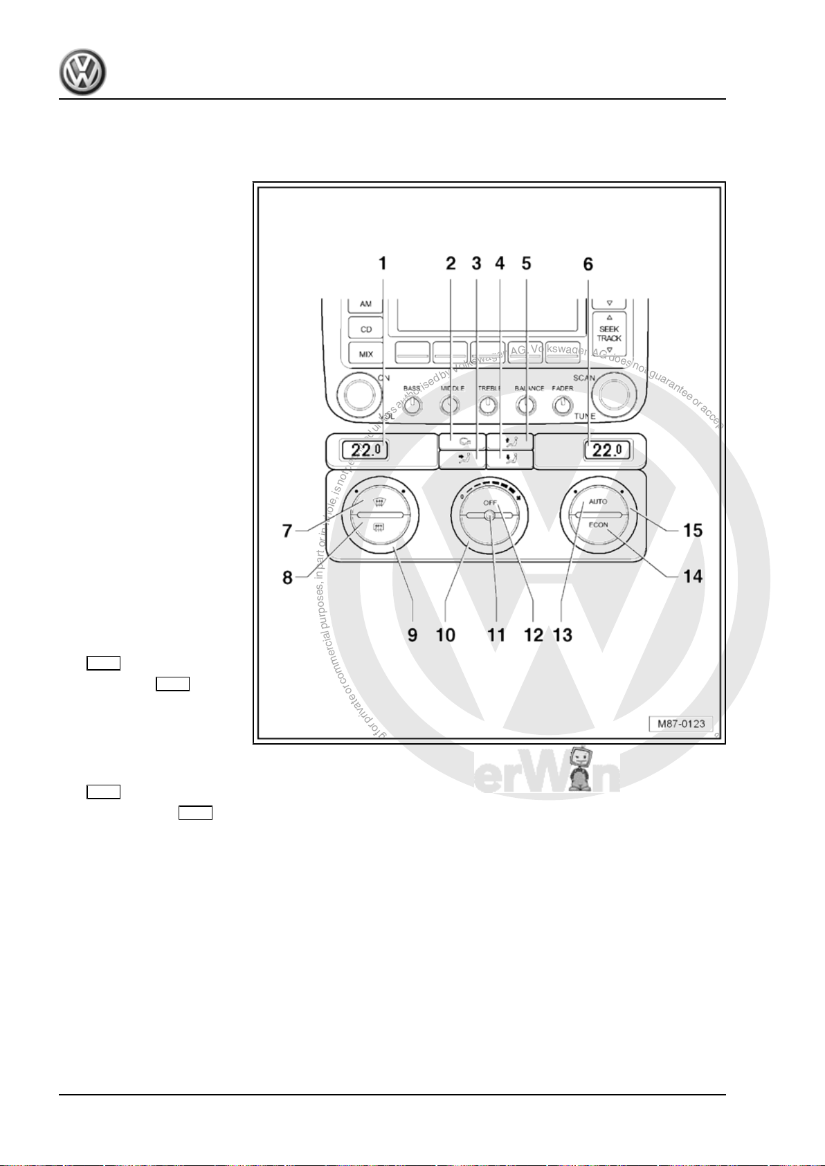
P
r
o
t
e
c
t
e
d
b
y
c
o
p
y
r
i
g
h
t
.
C
o
p
y
i
n
g
f
o
r
p
r
i
v
a
t
e
o
r
c
o
m
m
e
r
c
i
a
l
p
u
r
p
o
s
e
s
,
i
n
p
a
r
t
o
r
i
n
w
h
o
l
e
,
i
s
n
o
t
p
e
r
m
i
t
t
e
d
u
n
l
e
s
s
a
u
t
h
o
r
i
s
e
d
b
y
V
o
l
k
s
w
a
g
e
n
A
G
.
V
o
l
k
s
w
a
g
e
n
A
G
d
o
e
s
n
o
t
g
u
a
r
a
n
t
e
e
o
r
a
c
c
e
p
t
a
n
y
l
i
a
b
i
l
i
t
y
w
i
t
h
r
e
s
p
e
c
t
t
o
t
h
e
c
o
r
r
e
c
t
n
e
s
s
o
f
i
n
f
o
r
m
a
t
i
o
n
i
n
t
h
i
s
d
o
c
u
m
e
n
t
.
C
o
p
y
r
i
g
h
t
b
y
V
o
l
k
s
w
a
g
e
n
A
G
.
Golf Variant 2007 ➤ , Golf Variant 2010 ➤ , Jetta 2005 ➤ , Jetta 2011 ➤
Heating, air conditioning - Edition 04.2010
3.2 Function of operating and display unit for Climatronic air conditioning sys‐
tem -E87- (Golf Variant 2007►, Golf Variant 2010► und Jetta 2005►)
1 - Display for selected left in‐
terior temperature
2 - Air recirculation button
❑ Pressing the air recircu‐
lation button will prevent
polluted air from enter‐
ing the interior.
3 - Centre air distribution but‐
ton
4 - Lower air distribution button
5 - Upper air distribution button
6 - Display for selected right in‐
terior temperature
7 - Windscreen defrost button
8 - Rear window heating button
9 - Rotary knob for interior tem‐
perature, left
10 - Blower regulator
❑ Turn to change blower
speed.
11 - Interior temperature sen‐
sor
12 - Off button for heating, ven‐
tilation and air conditioning op‐
eration
13 - AUTO button
❑ Pressing AUTO
causes the Climatronic
button
to maintain the selected
interior temperature
completely automatical‐
ly. With this setting, the vent air temperature, the blower speed and the air distribution are controlled
automatically.
14 - ECON button
❑ Pressing the ECON button will set the air conditioner compressor to near-zero delivery. The heating and
ventilation operations continue to be controlled electronically.
15 - Rotary knob for interior temperature, right
56 Rep. gr.87 - Air conditioning system
Page 63
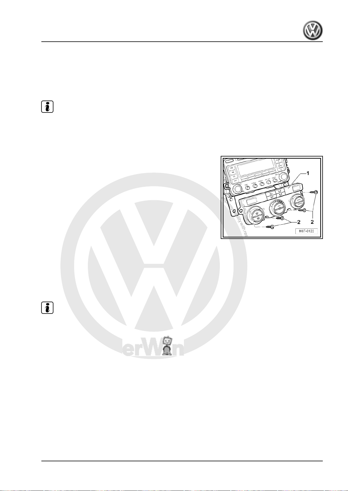
P
r
o
t
e
c
t
e
d
b
y
c
o
p
y
r
i
g
h
t
.
C
o
p
y
i
n
g
f
o
r
p
r
i
v
a
t
e
o
r
c
o
m
m
e
r
c
i
a
l
p
u
r
p
o
s
e
s
,
i
n
p
a
r
t
o
r
i
n
w
h
o
l
e
,
i
s
n
o
t
p
e
r
m
i
t
t
e
d
u
n
l
e
s
s
a
u
t
h
o
r
i
s
e
d
b
y
V
o
l
k
s
w
a
g
e
n
A
G
.
V
o
l
k
s
w
a
g
e
n
A
G
d
o
e
s
n
o
t
g
u
a
r
a
n
t
e
e
o
r
a
c
c
e
p
t
a
n
y
l
i
a
b
i
l
i
t
y
w
i
t
h
r
e
s
p
e
c
t
t
o
t
h
e
c
o
r
r
e
c
t
n
e
s
s
o
f
i
n
f
o
r
m
a
t
i
o
n
i
n
t
h
i
s
d
o
c
u
m
e
n
t
.
C
o
p
y
r
i
g
h
t
b
y
V
o
l
k
s
w
a
g
e
n
A
G
.
Golf Variant 2007 ➤ , Golf Variant 2010 ➤ , Jetta 2005 ➤ , Jetta 2011 ➤
Heating, air conditioning - Edition 04.2010
3.3 Removing and installing operating and
display unit for Climatronic air condition‐
ing system -E87- with Climatronic con‐
trol unit -J255- (Golf Variant 2007►, Golf
Variant 2010► und Jetta 2005►)
Note
The Climatronic control unit -J255- and the operating and display
unit for Climatronic air conditioning system -E87- are a single
component which cannot be dismantled.
3.3.1 Removing
– Remove dash panel centre trim ⇒ Rep. gr. 68 ; .
– Undo bolts -2- and remove operating and display unit for Cli‐
matronic air conditioning system -E87- -1- from dash panel.
– Disconnect connectors on operating and display unit for Cli‐
matronic air conditioning system -E87- .
3.3.2 Installing
Install in reverse order.
3.4 Function of operating and display unit
♦
for Climatronic air conditioning system E87- (Jetta 2011►)
Note
A warning lamp in the instrument panel controls will indicate
that the selected function is active. In addition, the display of
the radio or of the radio navigation system will indicate the
selected function for a short period when a button is pressed
or a regulator is operated.
♦
You can switch between °C and °F in the radio or radio navi‐
gation system display via the main menu in the dash panel
insert. Press rocker switch in windscreen wiper lever (or in
multifunction steering wheel) to call up main menu. Then se‐
lect Settings, Units and Temperature.
♦
If a new operating and display unit for Climatronic air condi‐
tioning system -E87- with Climatronic control unit -J255- is
installed, the basic setting and an adaptation („Compressor
first run“) must be carried out in the Guided Fault Finding or in
the Guided Functions.
3. Climatronic air conditioning with automatic regulation 57
Page 64
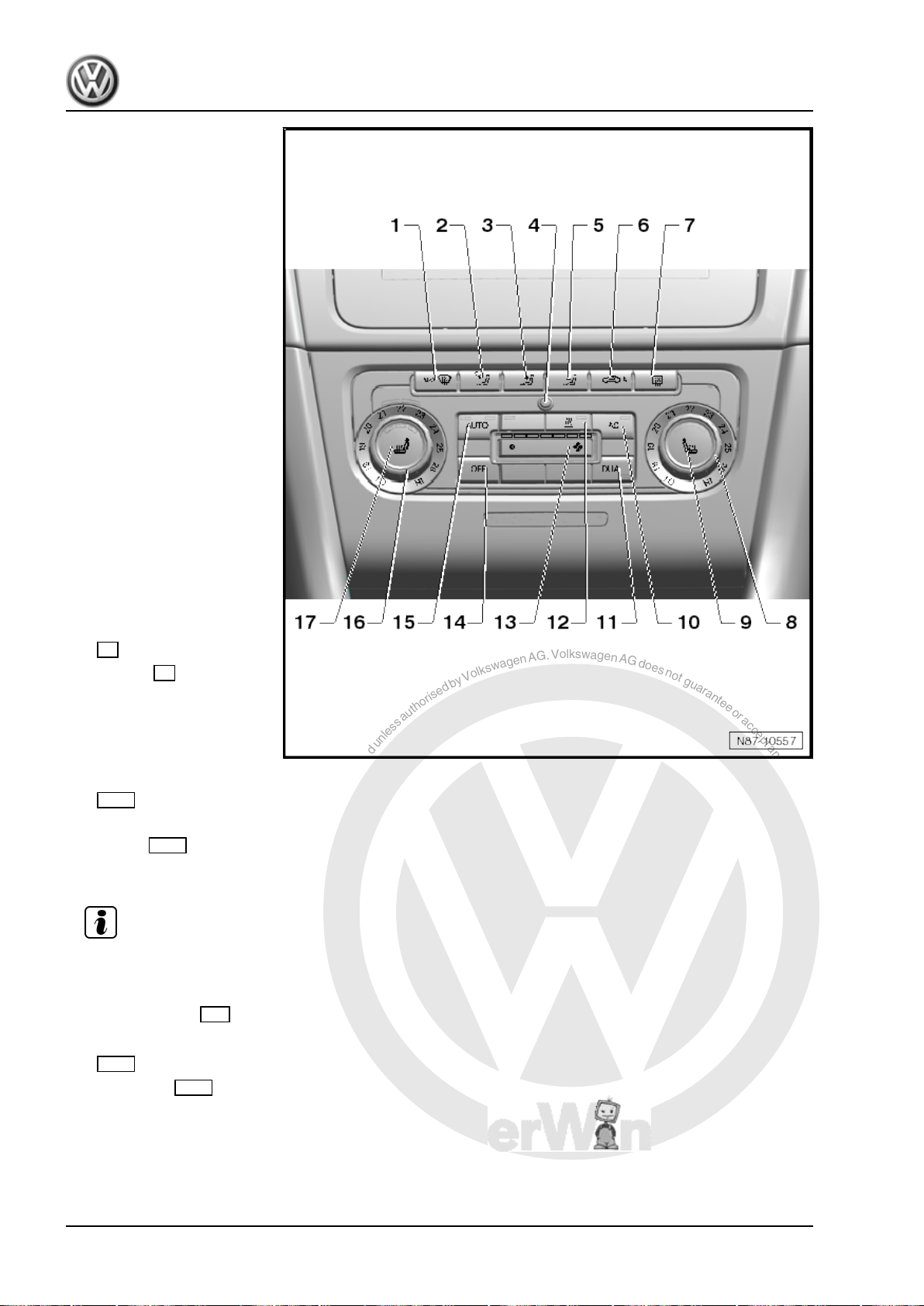
P
r
o
t
e
c
t
e
d
b
y
c
o
p
y
r
i
g
h
t
.
C
o
p
y
i
n
g
f
o
r
p
r
i
v
a
t
e
o
r
c
o
m
m
e
r
c
i
a
l
p
u
r
p
o
s
e
s
,
i
n
p
a
r
t
o
r
i
n
w
h
o
l
e
,
i
s
n
o
t
p
e
r
m
i
t
t
e
d
u
n
l
e
s
s
a
u
t
h
o
r
i
s
e
d
b
y
V
o
l
k
s
w
a
g
e
n
A
G
.
V
o
l
k
s
w
a
g
e
n
A
G
d
o
e
s
n
o
t
g
u
a
r
a
n
t
e
e
o
r
a
c
c
e
p
t
a
n
y
l
i
a
b
i
l
i
t
y
w
i
t
h
r
e
s
p
e
c
t
t
o
t
h
e
c
o
r
r
e
c
t
n
e
s
s
o
f
i
n
f
o
r
m
a
t
i
o
n
i
n
t
h
i
s
d
o
c
u
m
e
n
t
.
C
o
p
y
r
i
g
h
t
b
y
V
o
l
k
s
w
a
g
e
n
A
G
.
Golf Variant 2007 ➤ , Golf Variant 2010 ➤ , Jetta 2005 ➤ , Jetta 2011 ➤
Heating, air conditioning - Edition 04.2010
1 - Defrost function button for
windscreen
2 - Upper air distribution button
3 - Centre air distribution but‐
ton
4 - Interior temperature sensor
5 - Lower air distribution button
6 - Button for air recirculation
mode or for automatic recircu‐
lation mode
❑ Pressing the button for
air recirculation mode
will switch on the air re‐
circulation mode and
prevent polluted air from
entering the interior.
❑ Pressing the air recircu‐
lation mode button
again will activate the
automatic recirculation
mode.
7 - Rear window heating button
8 - Rotary knob for interior tem‐
perature, right
9 - Button for right seat heating
(optional)
10 - AC button
❑ Press AC
switch cooling on and
off.
❑ The warning lamp in the
button lights up when
the air conditioner com‐
pressor is switched on.
11 - DUAL button
❑ If the lamp in the button is on, the left and right temperatures may be adjusted independently.
❑ If the Dual button is pressed (the warning lamp goes out), the passenger side will assume the temper‐
ature setting for the driver side.
12 - Instant heating button -E537-
Note
13 - Blower regulator
❑ Press briefly to change blower speed.
14 - Air conditioner OFF
❑ Switches Climatronic on or off
15 - AUTO button
❑ Pressing AUTO button causes the Climatronic to maintain the selected interior temperature completely
automatically. With this setting, the vent air temperature, the blower speed and the air distribution are
controlled automatically.
16 - Rotary knob for interior temperature
button to
button
17 - Button for seat heating (optional)
58 Rep. gr.87 - Air conditioning system
Page 65
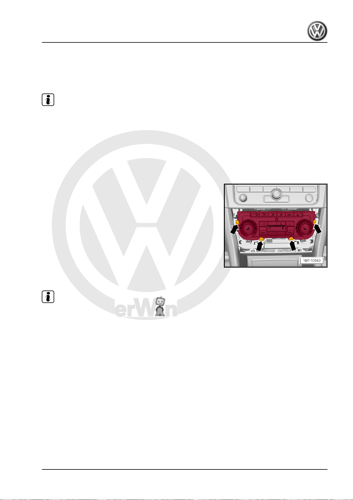
P
r
o
t
e
c
t
e
d
b
y
c
o
p
y
r
i
g
h
t
.
C
o
p
y
i
n
g
f
o
r
p
r
i
v
a
t
e
o
r
c
o
m
m
e
r
c
i
a
l
p
u
r
p
o
s
e
s
,
i
n
p
a
r
t
o
r
i
n
w
h
o
l
e
,
i
s
n
o
t
p
e
r
m
i
t
t
e
d
u
n
l
e
s
s
a
u
t
h
o
r
i
s
e
d
b
y
V
o
l
k
s
w
a
g
e
n
A
G
.
V
o
l
k
s
w
a
g
e
n
A
G
d
o
e
s
n
o
t
g
u
a
r
a
n
t
e
e
o
r
a
c
c
e
p
t
a
n
y
l
i
a
b
i
l
i
t
y
w
i
t
h
r
e
s
p
e
c
t
t
o
t
h
e
c
o
r
r
e
c
t
n
e
s
s
o
f
i
n
f
o
r
m
a
t
i
o
n
i
n
t
h
i
s
d
o
c
u
m
e
n
t
.
C
o
p
y
r
i
g
h
t
b
y
V
o
l
k
s
w
a
g
e
n
A
G
.
Golf Variant 2007 ➤ , Golf Variant 2010 ➤ , Jetta 2005 ➤ , Jetta 2011 ➤
Heating, air conditioning - Edition 04.2010
3.5 Removing and installing operating and
display unit for Climatronic air condition‐
ing system -E87- with Climatronic con‐
trol unit -J255- (Jetta 2011►)
Note
♦
The Climatronic control unit -J255- and the operating and dis‐
play unit for Climatronic air conditioning system -E87- are a
single component which cannot be dismantled.
♦
If a new operating and display unit for Climatronic air condi‐
tioning system -E87- with Climatronic control unit -J255- is
installed, the basic setting and an adaptation („Compressor
first run“) must be carried out in the Guided Fault Finding or in
the Guided Functions.
3.5.1 Removing
– Remove air conditioning system/heater control panel trim ⇒
– Undo bolts -arrows- (1.5 ± 0.2 Nm) and remove operating and
– Disconnect connectors on operating and display unit for Cli‐
3.5.2 Installing
Rep. gr. 68 .
display unit for Climatronic air conditioning system -E87- from
dash panel.
matronic air conditioning system -E87- .
Note
If a new operating and display unit for Climatronic air conditioning
system -E87- with Climatronic control unit -J255- is installed, the
basic setting and an adaptation („Compressor first run“) must be
carried out in the Guided Fault Finding or in the Guided Functions.
Install in reverse order. Observe specified toque for bolts (1.5 ±
0.2 Nm).
3.6 Connectors on Climatronic control unit J255-
3.6.1 Pin assignment for multi-pin connectors
A, B and C on back of Climatronic con‐
trol unit -J255-
Special tools and workshop equipment required
♦ Test adapter -V.A.G 1598/47-
3. Climatronic air conditioning with automatic regulation 59
Page 66
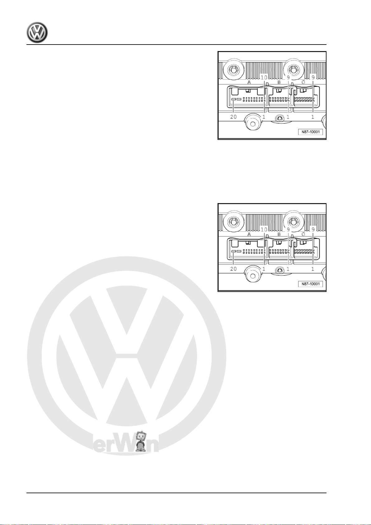
P
r
o
t
e
c
t
e
d
b
y
c
o
p
y
r
i
g
h
t
.
C
o
p
y
i
n
g
f
o
r
p
r
i
v
a
t
e
o
r
c
o
m
m
e
r
c
i
a
l
p
u
r
p
o
s
e
s
,
i
n
p
a
r
t
o
r
i
n
w
h
o
l
e
,
i
s
n
o
t
p
e
r
m
i
t
t
e
d
u
n
l
e
s
s
a
u
t
h
o
r
i
s
e
d
b
y
V
o
l
k
s
w
a
g
e
n
A
G
.
V
o
l
k
s
w
a
g
e
n
A
G
d
o
e
s
n
o
t
g
u
a
r
a
n
t
e
e
o
r
a
c
c
e
p
t
a
n
y
l
i
a
b
i
l
i
t
y
w
i
t
h
r
e
s
p
e
c
t
t
o
t
h
e
c
o
r
r
e
c
t
n
e
s
s
o
f
i
n
f
o
r
m
a
t
i
o
n
i
n
t
h
i
s
d
o
c
u
m
e
n
t
.
C
o
p
y
r
i
g
h
t
b
y
V
o
l
k
s
w
a
g
e
n
A
G
.
Golf Variant 2007 ➤ , Golf Variant 2010 ➤ , Jetta 2005 ➤ , Jetta 2011 ➤
Heating, air conditioning - Edition 04.2010
20-pin connector, T20c in current flow diagram -A-
1 - Sunlight penetration photosensor 2 -G134- or sunlight pene‐
tration photosensor -G107- , signal
2 - High-pressure sender -G65-
3 - Sunlight penetration photosensor 2 -G134- or sunlight pene‐
tration photosensor -G107- , signal
5 - CAN, high
6 - CAN, low
9 - + 5 V for sunlight penetration photosensor 2 -G134- or sunlight
penetration photosensor -G107-
16 - Positive connection (15a) for vehicles with supplementary
heating.
17 - Signal earth for sensors
18 - Air conditioning system compressor regulating valve -N280-
20 - Positive connection (15a) or positive connection (30a) for
vehicles with auxiliary heater
16-pin connector, T16g in current flow diagram -B-
1 - + 5V for control motors
2 - Potentiometer for left temperature flap control motor -G220-
3 - Potentiometer for right temperature flap control motor -G221-
4 - Potentiometer for defroster flap control motor -G135-
5 - Potentiometer for centre flap control motor -G112-
6 - Air recirculation flap control motor potentiometer -G143-
7 - Potentiometer for air flow flap control motor -G113-
8 - Left footwell vent temperature sender -G261-
9 - Right footwell vent temperature sender -G262-
10 - Fresh air intake duct temperature sensor -G89-
11 - Evaporator temperature sensor -G308-
14 - Signal earth, potentiometer
15 - Left vent temperature sender -G150-
16 - Right vent temperature sender -G151-
60 Rep. gr.87 - Air conditioning system
Page 67
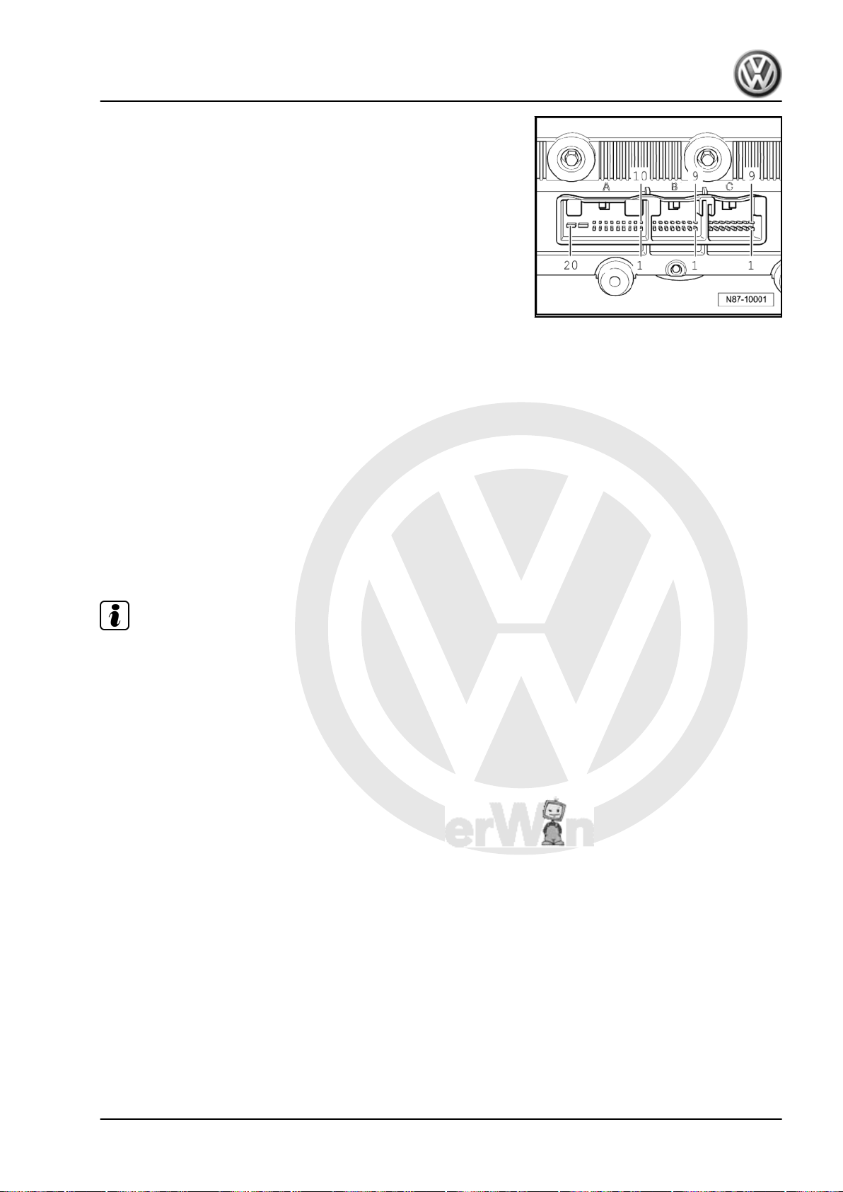
P
r
o
t
e
c
t
e
d
b
y
c
o
p
y
r
i
g
h
t
.
C
o
p
y
i
n
g
f
o
r
p
r
i
v
a
t
e
o
r
c
o
m
m
e
r
c
i
a
l
p
u
r
p
o
s
e
s
,
i
n
p
a
r
t
o
r
i
n
w
h
o
l
e
,
i
s
n
o
t
p
e
r
m
i
t
t
e
d
u
n
l
e
s
s
a
u
t
h
o
r
i
s
e
d
b
y
V
o
l
k
s
w
a
g
e
n
A
G
.
V
o
l
k
s
w
a
g
e
n
A
G
d
o
e
s
n
o
t
g
u
a
r
a
n
t
e
e
o
r
a
c
c
e
p
t
a
n
y
l
i
a
b
i
l
i
t
y
w
i
t
h
r
e
s
p
e
c
t
t
o
t
h
e
c
o
r
r
e
c
t
n
e
s
s
o
f
i
n
f
o
r
m
a
t
i
o
n
i
n
t
h
i
s
d
o
c
u
m
e
n
t
.
C
o
p
y
r
i
g
h
t
b
y
V
o
l
k
s
w
a
g
e
n
A
G
.
Golf Variant 2007 ➤ , Golf Variant 2010 ➤ , Jetta 2005 ➤ , Jetta 2011 ➤
Heating, air conditioning - Edition 04.2010
16-pin connector, T16f in current flow diagram -C-
1 - Left temperature flap control motor -V158- , cold
2 - Left temperature flap control motor -V158- , warm
3 - Defroster flap control motor -V107- , closed
4 - Defroster flap control motor -V107- , open
5 - Central flap control motor -V70- , chest
6 - Central flap control motor -V70- , footwell
7 - Fresh air and air recirculation flap control motor -V154- , re‐
circulated air activation
8 - Fresh air and air recirculation flap control motor -V154- , fresh
air activation
9 - Air flow flap control motor -V71- , open
10 - Air flow flap control motor -V71- , closed
11 - Right temperature flap control motor -V159- , cold
12 - Right temperature flap control motor -V159- , warm
15 - Fresh air blower -V2- (PWM actuated)
16 - Fresh air blower -V2- , feedback signal
3.7 Climatronic - passenger compartment
Note
♦
Disconnect battery before removing components marked ** ⇒
Rep. gr. 27 .
♦
A label indicates the type and quantity of refrigerant used.
(Golf Variant 2007►, Golf Variant 2010►
und Jetta 2005►)
3. Climatronic air conditioning with automatic regulation 61
Page 68
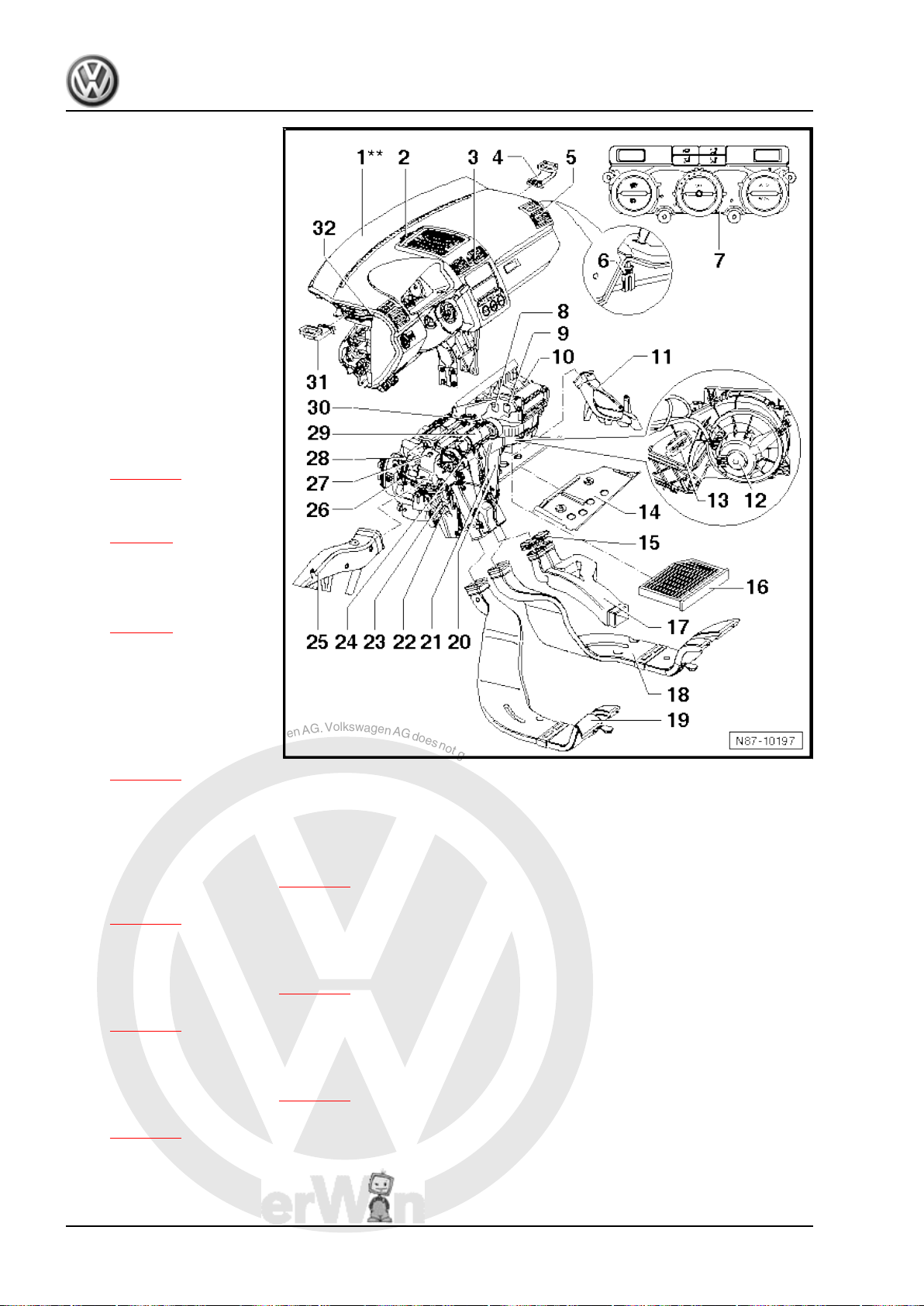
P
r
o
t
e
c
t
e
d
b
y
c
o
p
y
r
i
g
h
t
.
C
o
p
y
i
n
g
f
o
r
p
r
i
v
a
t
e
o
r
c
o
m
m
e
r
c
i
a
l
p
u
r
p
o
s
e
s
,
i
n
p
a
r
t
o
r
i
n
w
h
o
l
e
,
i
s
n
o
t
p
e
r
m
i
t
t
e
d
u
n
l
e
s
s
a
u
t
h
o
r
i
s
e
d
b
y
V
o
l
k
s
w
a
g
e
n
A
G
.
V
o
l
k
s
w
a
g
e
n
A
G
d
o
e
s
n
o
t
g
u
a
r
a
n
t
e
e
o
r
a
c
c
e
p
t
a
n
y
l
i
a
b
i
l
i
t
y
w
i
t
h
r
e
s
p
e
c
t
t
o
t
h
e
c
o
r
r
e
c
t
n
e
s
s
o
f
i
n
f
o
r
m
a
t
i
o
n
i
n
t
h
i
s
d
o
c
u
m
e
n
t
.
C
o
p
y
r
i
g
h
t
b
y
V
o
l
k
s
w
a
g
e
n
A
G
.
Golf Variant 2007 ➤ , Golf Variant 2010 ➤ , Jetta 2005 ➤ , Jetta 2011 ➤
Heating, air conditioning - Edition 04.2010
1 - Dash panel**
❑ Removing and installing
⇒ Rep. gr. 70
2 - Sunlight penetration photo‐
sensor -G107- or sunlight pen‐
etration photosensor 2 -G134-
❑ Checking: vehicle diag‐
nosis, testing and infor‐
mation system -VAS
5051B- .
❑ Function: controls tem‐
perature flap and fresh
air blower depending on
light intensity
❑ Emergency running in
event of failure: Clima‐
tronic control unit -J255assumes fixed value
❑ Removing and installing
⇒ page 78
3 - Centre vents
❑ Removing and installing
⇒ page 7
4 - Right side vent
5 - Vent
❑ Removing and installing
⇒ page 8
6 - Right vent temperature
sender -G151-
❑ Checking: vehicle diag‐
nosis, testing and infor‐
mation system -VAS
5051B- .
❑ Removing and installing
⇒ page 78
7 - Climatronic control unit -J255-
❑ The Climatronic control unit -J255- and the operating and display unit for Climatronic air conditioning
❑ Checking: vehicle diagnosis, testing and information system -VAS 5051B- .
❑ Removing and installing ⇒ page 57
❑ Renewing: initiate basic setting using vehicle diagnosis, testing and information system -VAS 5051B-
8 - Air flow flap control motor -V71-
❑ Checking: vehicle diagnosis, testing and information system -VAS 5051B- .
❑ Removing and installing ⇒ page 79
❑ Renewing: initiate basic setting using vehicle diagnosis, testing and information system -VAS 5051B-
9 - Fresh air and air recirculation flap control motor -V154-
❑ Checking: vehicle diagnosis, testing and information system -VAS 5051B- .
❑ Removing and installing ⇒ page 79
❑ Renewing: initiate basic setting using vehicle diagnosis, testing and information system -VAS 5051B-
system -E87- are a single component which cannot be dismantled.
⇒ page 55 .
⇒ page 55 .
⇒ page 55 .
10 - Fresh air intake duct temperature sensor -G89-
❑ Checking: vehicle diagnosis, testing and information system -VAS 5051B- .
❑ Function: temperature sensor controls temperature flap and fresh air blower, depending on temperature.
62 Rep. gr.87 - Air conditioning system
Page 69

P
r
o
t
e
c
t
e
d
b
y
c
o
p
y
r
i
g
h
t
.
C
o
p
y
i
n
g
f
o
r
p
r
i
v
a
t
e
o
r
c
o
m
m
e
r
c
i
a
l
p
u
r
p
o
s
e
s
,
i
n
p
a
r
t
o
r
i
n
w
h
o
l
e
,
i
s
n
o
t
p
e
r
m
i
t
t
e
d
u
n
l
e
s
s
a
u
t
h
o
r
i
s
e
d
b
y
V
o
l
k
s
w
a
g
e
n
A
G
.
V
o
l
k
s
w
a
g
e
n
A
G
d
o
e
s
n
o
t
g
u
a
r
a
n
t
e
e
o
r
a
c
c
e
p
t
a
n
y
l
i
a
b
i
l
i
t
y
w
i
t
h
r
e
s
p
e
c
t
t
o
t
h
e
c
o
r
r
e
c
t
n
e
s
s
o
f
i
n
f
o
r
m
a
t
i
o
n
i
n
t
h
i
s
d
o
c
u
m
e
n
t
.
C
o
p
y
r
i
g
h
t
b
y
V
o
l
k
s
w
a
g
e
n
A
G
.
Golf Variant 2007 ➤ , Golf Variant 2010 ➤ , Jetta 2005 ➤ , Jetta 2011 ➤
❑ Dash panel must be removed to remove and install the fresh air intake duct temperature sensor -G89-
⇒ Rep. gr. 70 .
11 - Right footwell vent
❑ Removing and installing ⇒ page 9
12 - Fresh air blower -V2- with fresh air blower control unit -J126-
❑ Checking: vehicle diagnosis, testing and information system -VAS 5051B- .
❑ Removing and installing ⇒ page 5
13 - Connector
14 - Baffle plate for heater unit
❑ Removing ⇒ page 3
15 - Sealing cap
❑ Fitted only in vehicles without air duct to vent in rear centre console.
16 - Dust and pollen filter
❑ With activated charcoal filter
❑ Removing and installing ⇒ page 6
17 - Connecting piece
❑ For centre console air duct.
❑ To remove, centre console must be removed ⇒ Rep. gr. 68 .
18 - Air duct for right rear footwell
❑ Removing and installing ⇒ page 8
19 - Air duct for left rear footwell
❑ Removing and installing ⇒ page 8
20 - Evaporator temperature sensor -G308-
❑ Checking: vehicle diagnosis, testing and information system -VAS 5051B- .
❑ Removing and installing ⇒ page 77
21 - Right temperature flap control motor -V159-
❑ Checking: vehicle diagnosis, testing and information system -VAS 5051B- .
❑ Removing and installing ⇒ page 82
❑ Renewing: initiate basic setting using vehicle diagnosis, testing and information system -VAS 5051B-
⇒ page 55 .
22 - Auxiliary air heater element -Z35-
❑ Installed only in vehicles with diesel engines without auxiliary coolant heater.
❑ Removing and installing ⇒ page 26
23 - Heat exchanger
❑ After renewing heat exchanger, renew coolant completely ⇒ Rep. gr. 19 .
❑ Removing and installing heat exchanger (Golf Variant 2007►, Golf Variant 2010► und Jetta 2005►)
⇒ page 19 .
24 - Central flap control motor -V70-
❑ Checking: vehicle diagnosis, testing and information system -VAS 5051B- .
❑ Removing and installing ⇒ page 83
❑ Renewing: initiate basic setting using vehicle diagnosis, testing and information system -VAS 5051B-
⇒ page 55 .
25 - Left footwell vent
❑ Removing and installing ⇒ page 9
26 - Left temperature flap control motor -V158-
❑ Checking: vehicle diagnosis, testing and information system -VAS 5051B- .
❑ Removing and installing ⇒ page 81
Heating, air conditioning - Edition 04.2010
3. Climatronic air conditioning with automatic regulation 63
Page 70

P
r
o
t
e
c
t
e
d
b
y
c
o
p
y
r
i
g
h
t
.
C
o
p
y
i
n
g
f
o
r
p
r
i
v
a
t
e
o
r
c
o
m
m
e
r
c
i
a
l
p
u
r
p
o
s
e
s
,
i
n
p
a
r
t
o
r
i
n
w
h
o
l
e
,
i
s
n
o
t
p
e
r
m
i
t
t
e
d
u
n
l
e
s
s
a
u
t
h
o
r
i
s
e
d
b
y
V
o
l
k
s
w
a
g
e
n
A
G
.
V
o
l
k
s
w
a
g
e
n
A
G
d
o
e
s
n
o
t
g
u
a
r
a
n
t
e
e
o
r
a
c
c
e
p
t
a
n
y
l
i
a
b
i
l
i
t
y
w
i
t
h
r
e
s
p
e
c
t
t
o
t
h
e
c
o
r
r
e
c
t
n
e
s
s
o
f
i
n
f
o
r
m
a
t
i
o
n
i
n
t
h
i
s
d
o
c
u
m
e
n
t
.
C
o
p
y
r
i
g
h
t
b
y
V
o
l
k
s
w
a
g
e
n
A
G
.
Golf Variant 2007 ➤ , Golf Variant 2010 ➤ , Jetta 2005 ➤ , Jetta 2011 ➤
Heating, air conditioning - Edition 04.2010
❑ Renewing: initiate basic setting using vehicle diagnosis, testing and information system -VAS 5051B-
⇒ page 55 .
27 - Left footwell vent temperature sender -G261-
❑ Checking: vehicle diagnosis, testing and information system -VAS 5051B- .
❑ Removing ⇒ page 76
28 - Defroster flap control motor -V107-
❑ Checking: vehicle diagnosis, testing and information system -VAS 5051B- .
❑ Removing and installing ⇒ page 80
❑ Renewing: initiate basic setting using vehicle diagnosis, testing and information system -VAS 5051B-
⇒ page 55 .
29 - Heater and air conditioning unit
❑ Removing and installing ⇒ page 68
❑ Dismantling and assembling ⇒ page 71
30 - Right footwell vent temperature sender -G262-
❑ Checking: vehicle diagnosis, testing and information system -VAS 5051B- .
❑ Removing ⇒ page 77
31 - Left side vent
32 - Left vent temperature sender -G150-
❑ Checking: vehicle diagnosis, testing and information system -VAS 5051B- .
❑ Removing and installing ⇒ page 78
64 Rep. gr.87 - Air conditioning system
Page 71
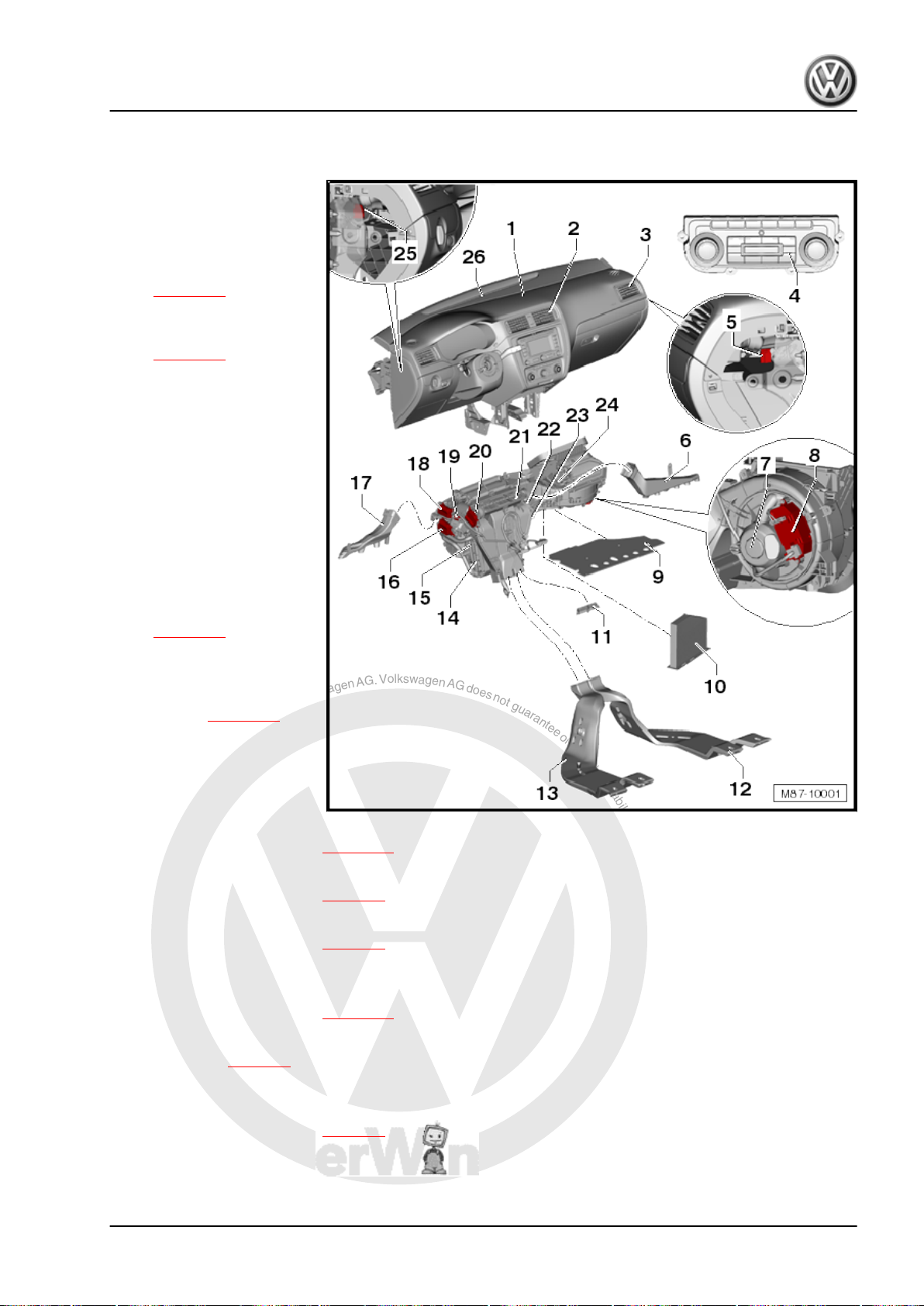
P
r
o
t
e
c
t
e
d
b
y
c
o
p
y
r
i
g
h
t
.
C
o
p
y
i
n
g
f
o
r
p
r
i
v
a
t
e
o
r
c
o
m
m
e
r
c
i
a
l
p
u
r
p
o
s
e
s
,
i
n
p
a
r
t
o
r
i
n
w
h
o
l
e
,
i
s
n
o
t
p
e
r
m
i
t
t
e
d
u
n
l
e
s
s
a
u
t
h
o
r
i
s
e
d
b
y
V
o
l
k
s
w
a
g
e
n
A
G
.
V
o
l
k
s
w
a
g
e
n
A
G
d
o
e
s
n
o
t
g
u
a
r
a
n
t
e
e
o
r
a
c
c
e
p
t
a
n
y
l
i
a
b
i
l
i
t
y
w
i
t
h
r
e
s
p
e
c
t
t
o
t
h
e
c
o
r
r
e
c
t
n
e
s
s
o
f
i
n
f
o
r
m
a
t
i
o
n
i
n
t
h
i
s
d
o
c
u
m
e
n
t
.
C
o
p
y
r
i
g
h
t
b
y
V
o
l
k
s
w
a
g
e
n
A
G
.
Golf Variant 2007 ➤ , Golf Variant 2010 ➤ , Jetta 2005 ➤ , Jetta 2011 ➤
Heating, air conditioning - Edition 04.2010
3.8 Climatronic - passenger compartment (Jetta 2011►)
1 - Dash panel
❑ Removing and installing
⇒ Rep. gr. 70
2 - Centre vents
❑ Removing and installing
⇒ page 10
3 - Vent
❑ Removing and installing
⇒ page 10
4 - Climatronic control unit J255-
❑ The Climatronic control
unit -J255- and the op‐
erating and display unit
for Climatronic air con‐
ditioning system -E87are a single component
which cannot be dis‐
mantled.
❑ Checking: vehicle diag‐
nosis, testing and infor‐
mation system -VAS
5051B- .
❑ Removing and installing
⇒ page 59
❑ Renewing: initiate basic
setting using vehicle di‐
agnosis, testing and in‐
formation system -VAS
5051B- ⇒ page 55 .
5 - Right vent temperature
sender -G151-
❑ Checking: vehicle diag‐
nosis, testing and infor‐
mation system -VAS
5051B- .
❑ Removing and installing ⇒ page 78
6 - Right footwell vent
❑ Removing and installing ⇒ page 9
7 - Fresh air blower -V2-
❑ Removing and installing ⇒ page 5 .
8 - Fresh air blower control unit -J126-
❑ Checking: vehicle diagnosis, testing and information system -VAS 5051B- .
❑ Removing and installing ⇒ page 67
9 - Baffle plate for heater unit
❑ Removing ⇒ page 3
10 - Dust and pollen filter
❑ With activated charcoal filter
❑ Removing and installing ⇒ page 6
11 - Sealing cap
❑ Fitted only in vehicles without air duct to vent in rear centre console.
3. Climatronic air conditioning with automatic regulation 65
Page 72

P
r
o
t
e
c
t
e
d
b
y
c
o
p
y
r
i
g
h
t
.
C
o
p
y
i
n
g
f
o
r
p
r
i
v
a
t
e
o
r
c
o
m
m
e
r
c
i
a
l
p
u
r
p
o
s
e
s
,
i
n
p
a
r
t
o
r
i
n
w
h
o
l
e
,
i
s
n
o
t
p
e
r
m
i
t
t
e
d
u
n
l
e
s
s
a
u
t
h
o
r
i
s
e
d
b
y
V
o
l
k
s
w
a
g
e
n
A
G
.
V
o
l
k
s
w
a
g
e
n
A
G
d
o
e
s
n
o
t
g
u
a
r
a
n
t
e
e
o
r
a
c
c
e
p
t
a
n
y
l
i
a
b
i
l
i
t
y
w
i
t
h
r
e
s
p
e
c
t
t
o
t
h
e
c
o
r
r
e
c
t
n
e
s
s
o
f
i
n
f
o
r
m
a
t
i
o
n
i
n
t
h
i
s
d
o
c
u
m
e
n
t
.
C
o
p
y
r
i
g
h
t
b
y
V
o
l
k
s
w
a
g
e
n
A
G
.
Golf Variant 2007 ➤ , Golf Variant 2010 ➤ , Jetta 2005 ➤ , Jetta 2011 ➤
Heating, air conditioning - Edition 04.2010
12 - Air duct for right rear footwell
❑ Removing and installing ⇒ page 8
13 - Air duct for left rear footwell
❑ Removing and installing ⇒ page 8
14 - Heat exchanger
❑ After renewing heat exchanger, renew coolant completely ⇒ Rep. gr. 19 .
❑ Removing and installing heat exchanger (Jetta 2010►) ⇒ page 23 .
15 - Auxiliary air heater element -Z35-
❑ Only in vehicles with diesel engines without auxiliary coolant heater.
❑ Removing and installing ⇒ page 26
16 - Left temperature flap control motor -V158-
❑ Checking: vehicle diagnosis, testing and information system -VAS 5051B- .
❑ Removing and installing ⇒ page 81
❑ Renewing: initiate basic setting using vehicle diagnosis, testing and information system -VAS 5051B-
⇒ page 55 .
17 - Left footwell vent
❑ Removing and installing ⇒ page 9
18 - Defroster flap control motor -V107-
❑ Checking: vehicle diagnosis, testing and information system -VAS 5051B- .
❑ Removing and installing ⇒ page 80
❑ Renewing: initiate basic setting using vehicle diagnosis, testing and information system -VAS 5051B-
⇒ page 55 .
19 - Central flap control motor -V70-
❑ Checking: vehicle diagnosis, testing and information system -VAS 5051B- .
❑ Removing and installing ⇒ page 83
❑ Renewing: initiate basic setting using vehicle diagnosis, testing and information system -VAS 5051B-
⇒ page 55 .
20 - Right temperature flap control motor -V159-
❑ Checking: vehicle diagnosis, testing and information system -VAS 5051B- .
❑ Removing and installing ⇒ page 82
❑ Renewing: initiate basic setting using vehicle diagnosis, testing and information system -VAS 5051B-
⇒ page 55 .
21 - Air flow flap control motor -V71-
❑ Checking: vehicle diagnosis, testing and information system -VAS 5051B- .
❑ Removing and installing ⇒ page 79
❑ Renewing: initiate basic setting using vehicle diagnosis, testing and information system -VAS 5051B-
⇒ page 55 .
22 - Evaporator temperature sensor -G308-
❑ Checking: vehicle diagnosis, testing and information system -VAS 5051B- .
❑ Removing and installing ⇒ page 77
23 - Fresh air and air recirculation flap control motor -V154-
❑ Checking: vehicle diagnosis, testing and information system -VAS 5051B- .
❑ Removing and installing ⇒ page 79
❑ Renewing: initiate basic setting using vehicle diagnosis, testing and information system -VAS 5051B-
⇒ page 55 .
24 - Fresh air intake duct temperature sensor -G89-
❑ Checking: vehicle diagnosis, testing and information system -VAS 5051B- .
❑ Function: temperature sensor controls temperature flap and fresh air blower, depending on temperature.
66 Rep. gr.87 - Air conditioning system
Page 73
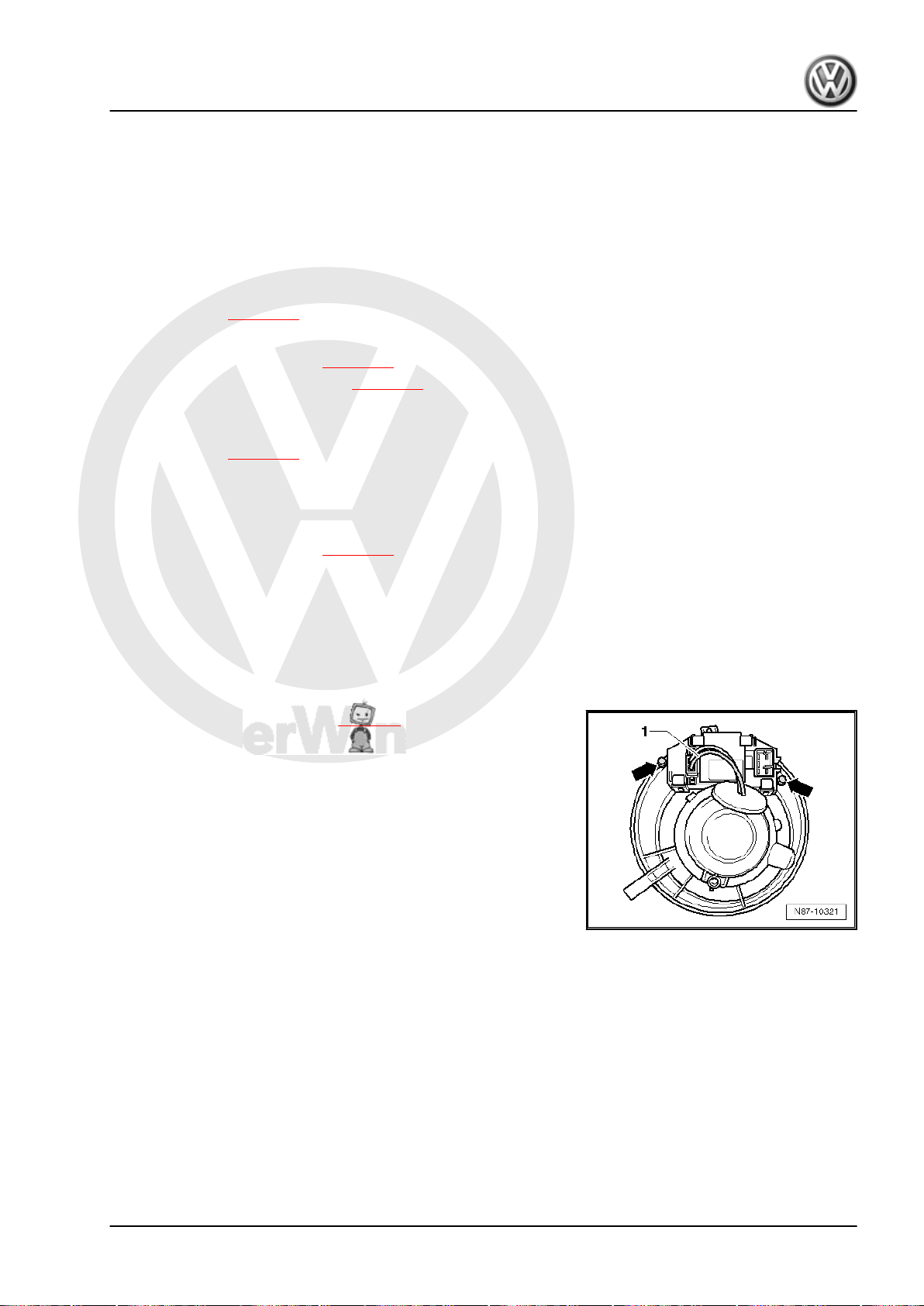
P
r
o
t
e
c
t
e
d
b
y
c
o
p
y
r
i
g
h
t
.
C
o
p
y
i
n
g
f
o
r
p
r
i
v
a
t
e
o
r
c
o
m
m
e
r
c
i
a
l
p
u
r
p
o
s
e
s
,
i
n
p
a
r
t
o
r
i
n
w
h
o
l
e
,
i
s
n
o
t
p
e
r
m
i
t
t
e
d
u
n
l
e
s
s
a
u
t
h
o
r
i
s
e
d
b
y
V
o
l
k
s
w
a
g
e
n
A
G
.
V
o
l
k
s
w
a
g
e
n
A
G
d
o
e
s
n
o
t
g
u
a
r
a
n
t
e
e
o
r
a
c
c
e
p
t
a
n
y
l
i
a
b
i
l
i
t
y
w
i
t
h
r
e
s
p
e
c
t
t
o
t
h
e
c
o
r
r
e
c
t
n
e
s
s
o
f
i
n
f
o
r
m
a
t
i
o
n
i
n
t
h
i
s
d
o
c
u
m
e
n
t
.
C
o
p
y
r
i
g
h
t
b
y
V
o
l
k
s
w
a
g
e
n
A
G
.
Golf Variant 2007 ➤ , Golf Variant 2010 ➤ , Jetta 2005 ➤ , Jetta 2011 ➤
❑ Dash panel must be removed to remove and install the fresh air intake duct temperature sensor -G89-
⇒ Rep. gr. 70 .
25 - Connector
26 - Connecting piece
❑ For centre console air duct.
❑ To remove, centre console must be removed ⇒ Rep. gr. 68 .
27 - Left footwell vent temperature sender -G261-
❑ Checking: vehicle diagnosis, testing and information system -VAS 5051B- .
❑ Removing ⇒ page 76
28 - Heater and air conditioning unit
❑ Removing and installing ⇒ page 68
❑ Dismantling and assembling ⇒ page 71
29 - Right footwell vent temperature sender -G262-
❑ Checking: vehicle diagnosis, testing and information system -VAS 5051B- .
❑ Removing ⇒ page 77
30 - Left side vent
31 - Left vent temperature sender -G150-
❑ Checking: vehicle diagnosis, testing and information system -VAS 5051B- .
❑ Removing and installing ⇒ page 78
3.9 Removing and installing fresh air blower
3.9.1 Removing
– Remove fresh air blower -V2- ⇒ page 5 .
control unit -J126-
– Disconnect connector -1- to fresh air blower -V2- .
– Undo bolts -arrows-.
Heating, air conditioning - Edition 04.2010
3.9.2 Installing
Install in reverse order.
3. Climatronic air conditioning with automatic regulation 67
Page 74
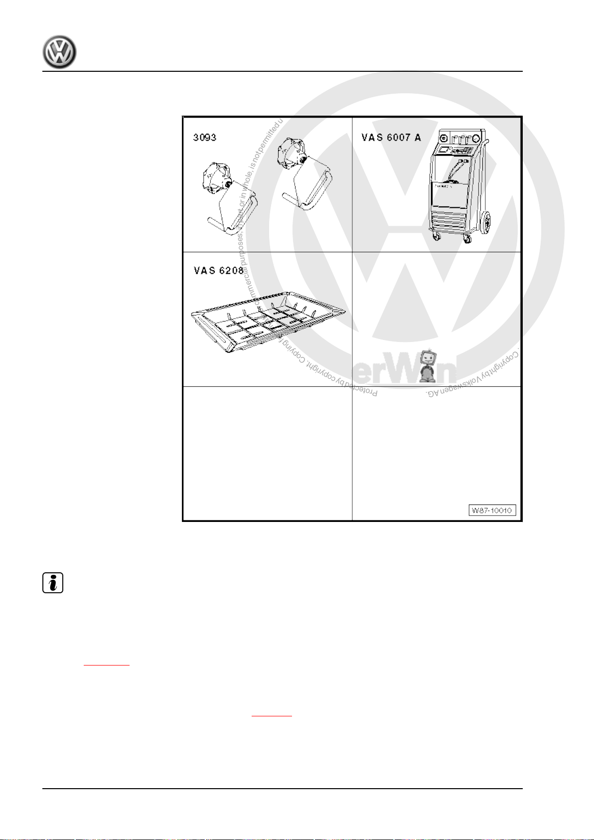
P
r
o
t
e
c
t
e
d
b
y
c
o
p
y
r
i
g
h
t
.
C
o
p
y
i
n
g
f
o
r
p
r
i
v
a
t
e
o
r
c
o
m
m
e
r
c
i
a
l
p
u
r
p
o
s
e
s
,
i
n
p
a
r
t
o
r
i
n
w
h
o
l
e
,
i
s
n
o
t
p
e
r
m
i
t
t
e
d
u
n
l
e
s
s
a
u
t
h
o
r
i
s
e
d
b
y
V
o
l
k
s
w
a
g
e
n
A
G
.
V
o
l
k
s
w
a
g
e
n
A
G
d
o
e
s
n
o
t
g
u
a
r
a
n
t
e
e
o
r
a
c
c
e
p
t
a
n
y
l
i
a
b
i
l
i
t
y
w
i
t
h
r
e
s
p
e
c
t
t
o
t
h
e
c
o
r
r
e
c
t
n
e
s
s
o
f
i
n
f
o
r
m
a
t
i
o
n
i
n
t
h
i
s
d
o
c
u
m
e
n
t
.
C
o
p
y
r
i
g
h
t
b
y
V
o
l
k
s
w
a
g
e
n
A
G
.
Golf Variant 2007 ➤ , Golf Variant 2010 ➤ , Jetta 2005 ➤ , Jetta 2011 ➤
Heating, air conditioning - Edition 04.2010
3.10 Removing and installing heater and air conditioning unit (Climatronic)
Special tools and workshop
equipment required
♦ Hose clamps up to 40 mm
-3093-
♦ E.g. air conditioner service
station -VAS 6007A- or lat‐
er model
♦ Drip tray for workshop hoist
-VAS 6208-
3.10.1 Removing
Note
To improve access, depending on engine version, additional com‐
ponents, e.g. engine cover must be removed ⇒ Rep. gr. 10 .
– Extract refrigerant, e.g. with air conditioner service station -
VAS 6007A- before opening refrigerant circuit. Comply with
notes ⇒ page 38 .
– Remove dash panel ⇒ Rep. gr. 70 .
– Remove bulkhead in plenum chamber ⇒ Rep. gr. 50 .
– Remove left and right rear footwell air ducts ⇒ page 8 .
68 Rep. gr.87 - Air conditioning system
Page 75
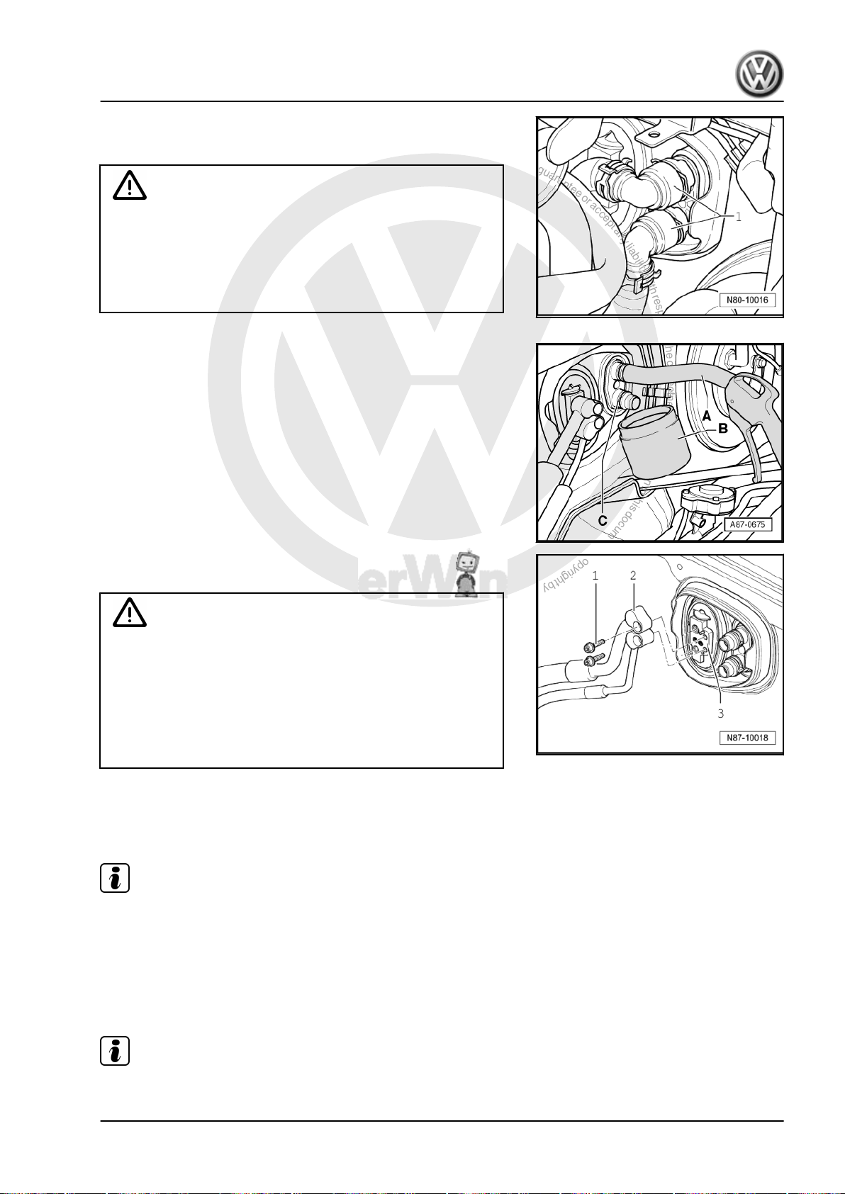
P
r
o
t
e
c
t
e
d
b
y
c
o
p
y
r
i
g
h
t
.
C
o
p
y
i
n
g
f
o
r
p
r
i
v
a
t
e
o
r
c
o
m
m
e
r
c
i
a
l
p
u
r
p
o
s
e
s
,
i
n
p
a
r
t
o
r
i
n
w
h
o
l
e
,
i
s
n
o
t
p
e
r
m
i
t
t
e
d
u
n
l
e
s
s
a
u
t
h
o
r
i
s
e
d
b
y
V
o
l
k
s
w
a
g
e
n
A
G
.
V
o
l
k
s
w
a
g
e
n
A
G
d
o
e
s
n
o
t
g
u
a
r
a
n
t
e
e
o
r
a
c
c
e
p
t
a
n
y
l
i
a
b
i
l
i
t
y
w
i
t
h
r
e
s
p
e
c
t
t
o
t
h
e
c
o
r
r
e
c
t
n
e
s
s
o
f
i
n
f
o
r
m
a
t
i
o
n
i
n
t
h
i
s
d
o
c
u
m
e
n
t
.
C
o
p
y
r
i
g
h
t
b
y
V
o
l
k
s
w
a
g
e
n
A
G
.
Golf Variant 2007 ➤ , Golf Variant 2010 ➤ , Jetta 2005 ➤ , Jetta 2011 ➤
Heating, air conditioning - Edition 04.2010
– Place drip tray -VAS 6208- beneath engine.
– Mark coolant hoses -1-.
WARNING
Danger of scalding injuries.
When the engine is warm, the coolant temperature may be
above 100 °C. The cooling system is pressurised.
If necessary, release pressure and reduce temperature before
carrying out repairs.
– Clamp off coolant hoses -1- with hose clamps up to 40 mm Ø
-VAS 3093- and disconnect coolant hoses to heat exchanger.
– Push a piece of hose -A- onto upper union.
– Hold a container -B- under lower connection -C-.
– Carefully blow remaining coolant out through unions of heat
exchanger using a compressed air pistol.
WARNING
Danger of freezing injuries.
If refrigerant circuit has not been evacuated, refrigerant will
escape.
Extract refrigerant before opening refrigerant circuit. If the re‐
frigerant circuit is not opened within 10 minutes after it has
been evacuated, pressure may develop in coolant circuit due
to re-evaporation. Extract refrigerant again.
– From engine compartment, undo bolts -1- for refrigerant lines
-2-.
– Take refrigerant lines out of expansion valve -3-.
Note
♦
Seal open connections for lines.
♦
To seal open connections of expansion valve, use, for exam‐
ple, sealing cap of a spare expansion valve.
– Cover carpet in interior of vehicle with a waterproof foil and
water absorbing paper.
Note
During removal, note lengths and locations of bolts for later installation.
3. Climatronic air conditioning with automatic regulation 69
Page 76
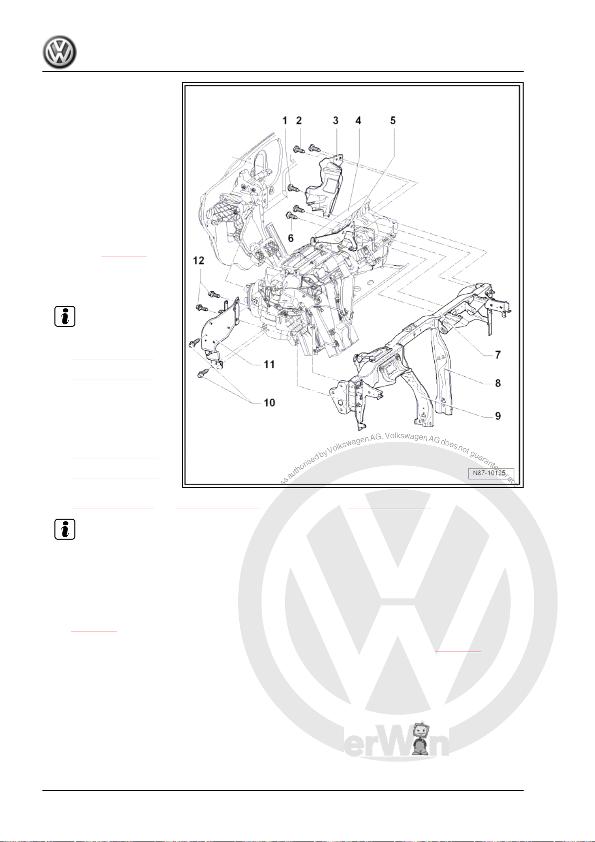
P
r
o
t
e
c
t
e
d
b
y
c
o
p
y
r
i
g
h
t
.
C
o
p
y
i
n
g
f
o
r
p
r
i
v
a
t
e
o
r
c
o
m
m
e
r
c
i
a
l
p
u
r
p
o
s
e
s
,
i
n
p
a
r
t
o
r
i
n
w
h
o
l
e
,
i
s
n
o
t
p
e
r
m
i
t
t
e
d
u
n
l
e
s
s
a
u
t
h
o
r
i
s
e
d
b
y
V
o
l
k
s
w
a
g
e
n
A
G
.
V
o
l
k
s
w
a
g
e
n
A
G
d
o
e
s
n
o
t
g
u
a
r
a
n
t
e
e
o
r
a
c
c
e
p
t
a
n
y
l
i
a
b
i
l
i
t
y
w
i
t
h
r
e
s
p
e
c
t
t
o
t
h
e
c
o
r
r
e
c
t
n
e
s
s
o
f
i
n
f
o
r
m
a
t
i
o
n
i
n
t
h
i
s
d
o
c
u
m
e
n
t
.
C
o
p
y
r
i
g
h
t
b
y
V
o
l
k
s
w
a
g
e
n
A
G
.
Golf Variant 2007 ➤ , Golf Variant 2010 ➤ , Jetta 2005 ➤ , Jetta 2011 ➤
Heating, air conditioning - Edition 04.2010
1 - Bolt
❑ 4 Nm
2 - Bolts
❑ Qty. 2
❑ 4 Nm
3 - Cable retainer
4 - Heater and air conditioning
unit
❑ Removing:
– Take condensation wa‐
ter drainage hose off
heater and air condition‐
er unit ⇒ page 79 .
– Disconnect connectors
from heater and air con‐
ditioner unit.
Note
– Undo bolts
⇒ Item 6 (page 70)
from bracket
⇒ Item 5 (page 70) .
– Remove support
⇒ Item 8 (page 70) .
– Remove bolts
⇒ Item 10 (page 70)
and
⇒ Item 12 (page 71)
and remove bracket
⇒ Item 11 (page 71) .
– Undo bolts
⇒ Item 2 (page 70) and ⇒ Item 1 (page 70) from cable retainer ⇒ Item 3 (page 70) .
Note
– Remove heater and air conditioning unit.
Installing:
Install in reverse order. Note the following when doing this:
– During installation, observe position of heating and air conditioner unit/engine compartment seal
⇒ page 71 .
– When installing, ensure that condensation water drainage hose is correctly seated ⇒ page 79 .
– Fill with coolant ⇒ Rep. gr. 19 .
5 - Bracket
6 - Bolts
❑ 8 Nm
7 - Assembly carrier
8 - Right support
9 - Left support
70 Rep. gr.87 - Air conditioning system
Page 77
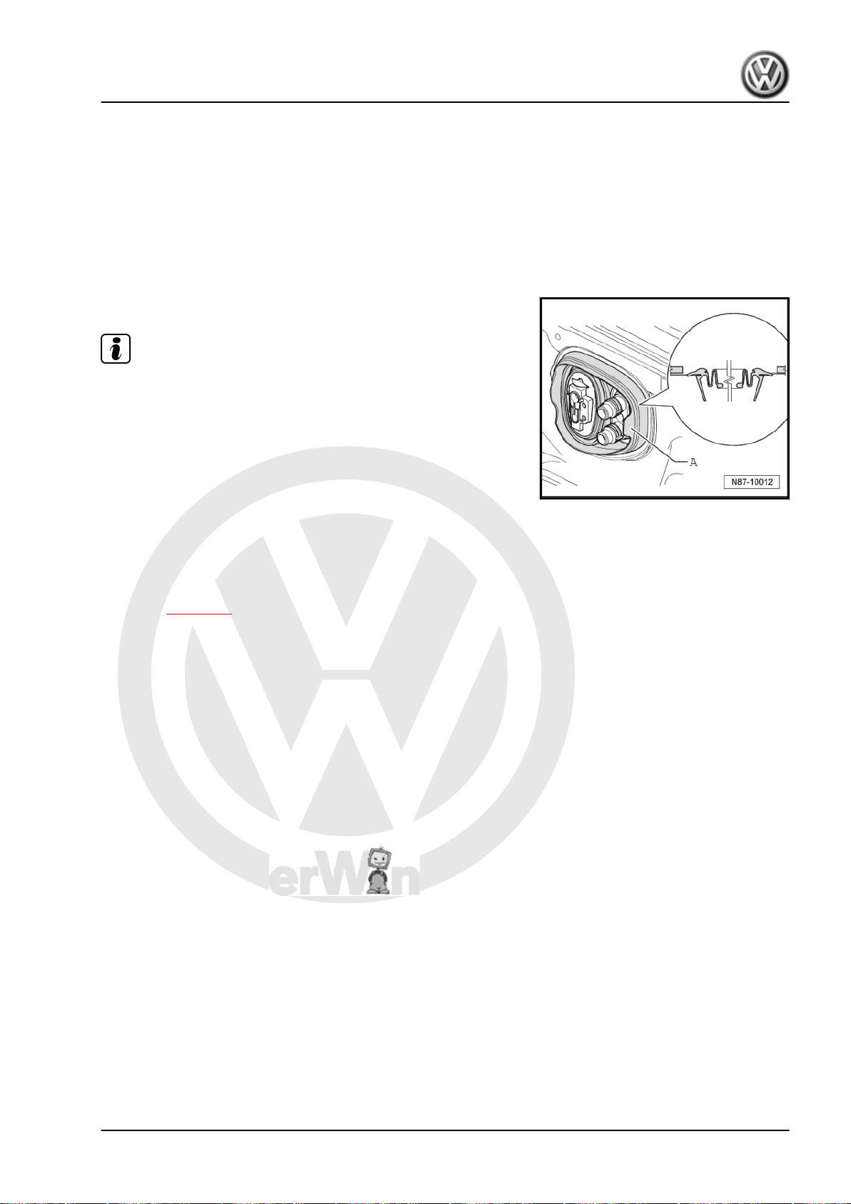
P
r
o
t
e
c
t
e
d
b
y
c
o
p
y
r
i
g
h
t
.
C
o
p
y
i
n
g
f
o
r
p
r
i
v
a
t
e
o
r
c
o
m
m
e
r
c
i
a
l
p
u
r
p
o
s
e
s
,
i
n
p
a
r
t
o
r
i
n
w
h
o
l
e
,
i
s
n
o
t
p
e
r
m
i
t
t
e
d
u
n
l
e
s
s
a
u
t
h
o
r
i
s
e
d
b
y
V
o
l
k
s
w
a
g
e
n
A
G
.
V
o
l
k
s
w
a
g
e
n
A
G
d
o
e
s
n
o
t
g
u
a
r
a
n
t
e
e
o
r
a
c
c
e
p
t
a
n
y
l
i
a
b
i
l
i
t
y
w
i
t
h
r
e
s
p
e
c
t
t
o
t
h
e
c
o
r
r
e
c
t
n
e
s
s
o
f
i
n
f
o
r
m
a
t
i
o
n
i
n
t
h
i
s
d
o
c
u
m
e
n
t
.
C
o
p
y
r
i
g
h
t
b
y
V
o
l
k
s
w
a
g
e
n
A
G
.
Golf Variant 2007 ➤ , Golf Variant 2010 ➤ , Jetta 2005 ➤ , Jetta 2011 ➤
Heating, air conditioning - Edition 04.2010
10 - Bolts
❑ Qty. 2
❑ 8 Nm
11 - Bracket
12 - Bolts
❑ Qty. 2
❑ 8 Nm
Heater and air conditioning unit/engine compartment seal
Note
Observe position of seal -A- during installation.
3.11 Dismantling and assembling heater and
Dismantling and assembling heater and air conditioning unit (Jet‐
ta 2011►) ⇒ page 73 .
air conditioning unit (Golf Variant 2007►,
Golf Variant 2010► und Jetta 2005►)
3. Climatronic air conditioning with automatic regulation 71
Page 78
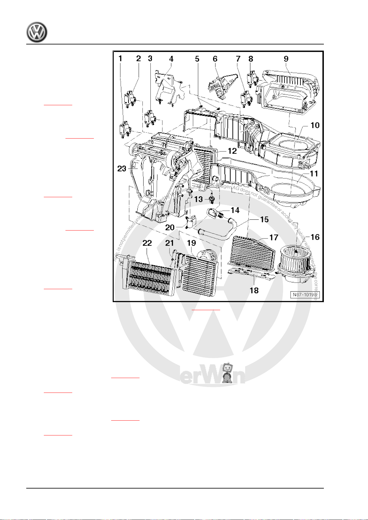
P
r
o
t
e
c
t
e
d
b
y
c
o
p
y
r
i
g
h
t
.
C
o
p
y
i
n
g
f
o
r
p
r
i
v
a
t
e
o
r
c
o
m
m
e
r
c
i
a
l
p
u
r
p
o
s
e
s
,
i
n
p
a
r
t
o
r
i
n
w
h
o
l
e
,
i
s
n
o
t
p
e
r
m
i
t
t
e
d
u
n
l
e
s
s
a
u
t
h
o
r
i
s
e
d
b
y
V
o
l
k
s
w
a
g
e
n
A
G
.
V
o
l
k
s
w
a
g
e
n
A
G
d
o
e
s
n
o
t
g
u
a
r
a
n
t
e
e
o
r
a
c
c
e
p
t
a
n
y
l
i
a
b
i
l
i
t
y
w
i
t
h
r
e
s
p
e
c
t
t
o
t
h
e
c
o
r
r
e
c
t
n
e
s
s
o
f
i
n
f
o
r
m
a
t
i
o
n
i
n
t
h
i
s
d
o
c
u
m
e
n
t
.
C
o
p
y
r
i
g
h
t
b
y
V
o
l
k
s
w
a
g
e
n
A
G
.
Golf Variant 2007 ➤ , Golf Variant 2010 ➤ , Jetta 2005 ➤ , Jetta 2011 ➤
Heating, air conditioning - Edition 04.2010
1 - Central flap control motor V70-
❑ Checking: vehicle diag‐
nosis, testing and infor‐
mation system -VAS
5051B- .
❑ Removing and installing
⇒ page 83
❑ Renewing: initiate basic
setting using vehicle di‐
agnosis, testing and in‐
formation system -VAS
5051B- ⇒ page 55 .
2 - Left temperature flap con‐
trol motor -V158-
❑ Checking: vehicle diag‐
nosis, testing and infor‐
mation system -VAS
5051B- .
❑ Removing and installing
⇒ page 81
❑ Renewing: initiate basic
setting using vehicle di‐
agnosis, testing and in‐
formation system -VAS
5051B- ⇒ page 55 .
3 - Defroster flap control motor
-V107❑ Checking: vehicle diag‐
nosis, testing and infor‐
mation system -VAS
5051B- .
❑ Removing and installing
⇒ page 80
❑ Renewing: initiate basic
setting using vehicle di‐
agnosis, testing and information system -VAS 5051B- ⇒ page 55 .
4 - Bracket
5 - Bolts
❑ Bolts must be removed to separate air distribution housing from evaporator housing.
6 - Cover
7 - Fresh air and air recirculation flap control motor -V154-
❑ Checking: vehicle diagnosis, testing and information system -VAS 5051B- .
❑ Removing and installing ⇒ page 79
❑ Renewing: initiate basic setting using vehicle diagnosis, testing and information system -VAS 5051B-
⇒ page 55 .
8 - Air flow flap control motor -V71-
❑ Checking: vehicle diagnosis, testing and information system -VAS 5051B- .
❑ Removing and installing ⇒ page 79
❑ Renewing: initiate basic setting using vehicle diagnosis, testing and information system -VAS 5051B-
⇒ page 55 .
9 - Air intake housing
❑ With air recirculation flap
❑ With air flow flap (Climatronic).
72 Rep. gr.87 - Air conditioning system
Page 79

P
r
o
t
e
c
t
e
d
b
y
c
o
p
y
r
i
g
h
t
.
C
o
p
y
i
n
g
f
o
r
p
r
i
v
a
t
e
o
r
c
o
m
m
e
r
c
i
a
l
p
u
r
p
o
s
e
s
,
i
n
p
a
r
t
o
r
i
n
w
h
o
l
e
,
i
s
n
o
t
p
e
r
m
i
t
t
e
d
u
n
l
e
s
s
a
u
t
h
o
r
i
s
e
d
b
y
V
o
l
k
s
w
a
g
e
n
A
G
.
V
o
l
k
s
w
a
g
e
n
A
G
d
o
e
s
n
o
t
g
u
a
r
a
n
t
e
e
o
r
a
c
c
e
p
t
a
n
y
l
i
a
b
i
l
i
t
y
w
i
t
h
r
e
s
p
e
c
t
t
o
t
h
e
c
o
r
r
e
c
t
n
e
s
s
o
f
i
n
f
o
r
m
a
t
i
o
n
i
n
t
h
i
s
d
o
c
u
m
e
n
t
.
C
o
p
y
r
i
g
h
t
b
y
V
o
l
k
s
w
a
g
e
n
A
G
.
Golf Variant 2007 ➤ , Golf Variant 2010 ➤ , Jetta 2005 ➤ , Jetta 2011 ➤
Heating, air conditioning - Edition 04.2010
10 - Evaporator housing - upper part
❑ Dismantling and assembling evaporator housing ⇒ page 75
11 - Evaporator housing - lower part
❑ Dismantling and assembling evaporator housing ⇒ page 75
12 - Evaporator
❑ Removing and installing ⇒ page 99
13 - Evaporator temperature sensor -G308-
❑ Checking: vehicle diagnosis, testing and information system -VAS 5051B- .
❑ Removing and installing ⇒ page 77
14 - Connection for glove compartment cooling
15 - Cooling hose for glove compartment
16 - Fresh air blower -V2- with fresh air blower series resistor with overheating fuse -N24-
17 - Dust and pollen filter
18 - Cover
19 - Heat exchanger
❑ Checking: vehicle diagnosis, testing and information system -VAS 5051B- .
❑ Removing and installing ⇒ page 5
❑ With activated charcoal filter
❑ Removing and installing ⇒ page 5
❑ For dust and pollen filter.
❑ After renewing heat exchanger, renew coolant completely ⇒ Rep. gr. 19 .
❑ Removing and installing heat exchanger (Golf Variant 2007►, Golf Variant 2010► und Jetta 2005►)
⇒ page 19 .
20 - Right temperature flap control motor -V159-
❑ Checking: vehicle diagnosis, testing and information system -VAS 5051B- .
❑ Removing and installing ⇒ page 82
❑ Renewing: initiate basic setting using vehicle diagnosis, testing and information system -VAS 5051B-
⇒ page 55 .
21 - Heat exchanger cladding
22 - Auxiliary air heater element -Z35-
❑ Installed only in vehicles with diesel engines without auxiliary coolant heater.
❑ Removing and installing ⇒ page 26 .
23 - Air distribution housing
3.12 Dismantling and assembling heater and air conditioning unit (Jetta 2011►)
Dismantling and assembling heater and air conditioning unit (Golf
Variant 2007►, Golf Variant 2010► und Jetta 2005►) ⇒ page 71 .
3. Climatronic air conditioning with automatic regulation 73
Page 80
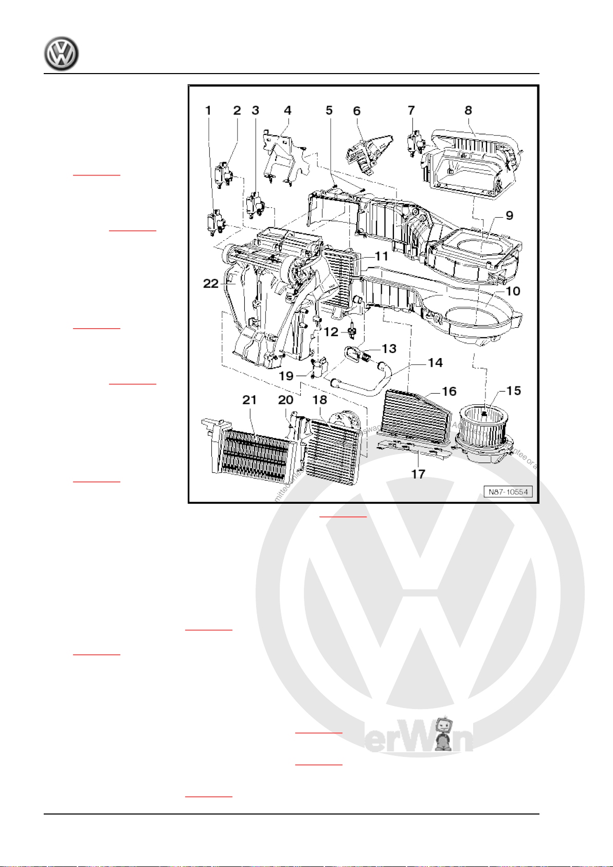
P
r
o
t
e
c
t
e
d
b
y
c
o
p
y
r
i
g
h
t
.
C
o
p
y
i
n
g
f
o
r
p
r
i
v
a
t
e
o
r
c
o
m
m
e
r
c
i
a
l
p
u
r
p
o
s
e
s
,
i
n
p
a
r
t
o
r
i
n
w
h
o
l
e
,
i
s
n
o
t
p
e
r
m
i
t
t
e
d
u
n
l
e
s
s
a
u
t
h
o
r
i
s
e
d
b
y
V
o
l
k
s
w
a
g
e
n
A
G
.
V
o
l
k
s
w
a
g
e
n
A
G
d
o
e
s
n
o
t
g
u
a
r
a
n
t
e
e
o
r
a
c
c
e
p
t
a
n
y
l
i
a
b
i
l
i
t
y
w
i
t
h
r
e
s
p
e
c
t
t
o
t
h
e
c
o
r
r
e
c
t
n
e
s
s
o
f
i
n
f
o
r
m
a
t
i
o
n
i
n
t
h
i
s
d
o
c
u
m
e
n
t
.
C
o
p
y
r
i
g
h
t
b
y
V
o
l
k
s
w
a
g
e
n
A
G
.
Golf Variant 2007 ➤ , Golf Variant 2010 ➤ , Jetta 2005 ➤ , Jetta 2011 ➤
Heating, air conditioning - Edition 04.2010
1 - Central flap control motor V70-
❑ Checking: vehicle diag‐
nosis, testing and infor‐
mation system -VAS
5051B- .
❑ Removing and installing
⇒ page 83
❑ Renewing: initiate basic
setting using vehicle di‐
agnosis, testing and in‐
formation system -VAS
5051B- ⇒ page 55 .
2 - Left temperature flap con‐
trol motor -V158-
❑ Checking: vehicle diag‐
nosis, testing and infor‐
mation system -VAS
5051B- .
❑ Removing and installing
⇒ page 81
❑ Renewing: initiate basic
setting using vehicle di‐
agnosis, testing and in‐
formation system -VAS
5051B- ⇒ page 55 .
3 - Defroster flap control motor
-V107❑ Checking: vehicle diag‐
nosis, testing and infor‐
mation system -VAS
5051B- .
❑ Removing and installing
⇒ page 80
❑ Renewing: initiate basic
setting using vehicle di‐
agnosis, testing and information system -VAS 5051B- ⇒ page 55 .
4 - Bracket
5 - Bolts
❑ Bolts must be removed to separate air distribution housing from evaporator housing.
6 - Cover
7 - Control motor for fresh air and air recirculation flap and air flow flap -V425-
❑ Checking: vehicle diagnosis, testing and information system -VAS 5051B- .
❑ Removing and installing ⇒ page 79
❑ Renewing: initiate basic setting using vehicle diagnosis, testing and information system -VAS 5051B-
⇒ page 55 .
8 - Air intake housing
❑ With air recirculation flap
❑ With air flow flap (Climatronic).
9 - Evaporator housing - upper part
❑ Dismantling and assembling evaporator housing ⇒ page 75
10 - Evaporator housing - lower part
❑ Dismantling and assembling evaporator housing ⇒ page 75
11 - Evaporator
❑ Removing and installing ⇒ page 99
74 Rep. gr.87 - Air conditioning system
Page 81
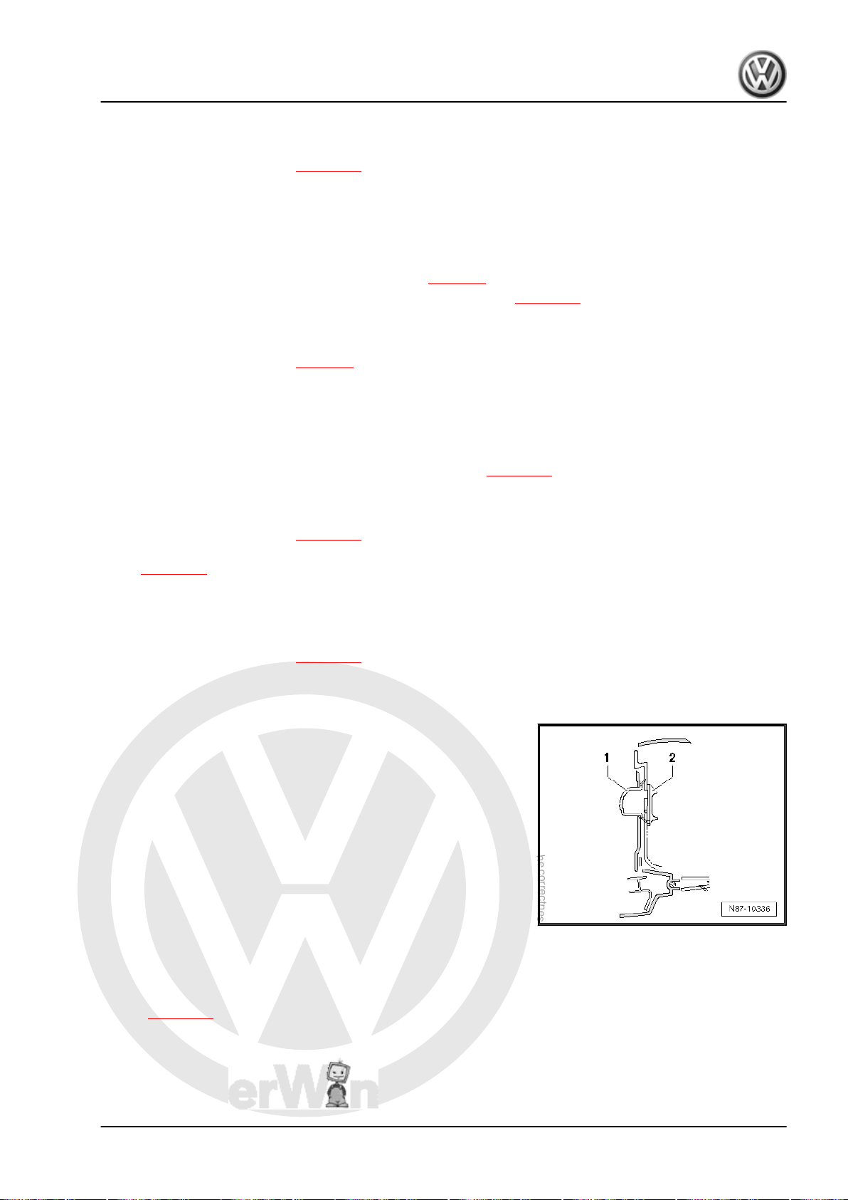
P
r
o
t
e
c
t
e
d
b
y
c
o
p
y
r
i
g
h
t
.
C
o
p
y
i
n
g
f
o
r
p
r
i
v
a
t
e
o
r
c
o
m
m
e
r
c
i
a
l
p
u
r
p
o
s
e
s
,
i
n
p
a
r
t
o
r
i
n
w
h
o
l
e
,
i
s
n
o
t
p
e
r
m
i
t
t
e
d
u
n
l
e
s
s
a
u
t
h
o
r
i
s
e
d
b
y
V
o
l
k
s
w
a
g
e
n
A
G
.
V
o
l
k
s
w
a
g
e
n
A
G
d
o
e
s
n
o
t
g
u
a
r
a
n
t
e
e
o
r
a
c
c
e
p
t
a
n
y
l
i
a
b
i
l
i
t
y
w
i
t
h
r
e
s
p
e
c
t
t
o
t
h
e
c
o
r
r
e
c
t
n
e
s
s
o
f
i
n
f
o
r
m
a
t
i
o
n
i
n
t
h
i
s
d
o
c
u
m
e
n
t
.
C
o
p
y
r
i
g
h
t
b
y
V
o
l
k
s
w
a
g
e
n
A
G
.
Golf Variant 2007 ➤ , Golf Variant 2010 ➤ , Jetta 2005 ➤ , Jetta 2011 ➤
12 - Evaporator temperature sensor -G308-
❑ Checking: vehicle diagnosis, testing and information system -VAS 5051B- .
❑ Removing and installing ⇒ page 77
13 - Connection for glove compartment cooling
14 - Cooling hose for glove compartment
15 - Fresh air blower -V2- with fresh air blower control unit -J126-
❑ Checking: vehicle diagnosis, testing and information system -VAS 5051B- .
❑ Removing and installing fresh air blower -V2- ⇒ page 5
❑ Removing and installing fresh air blower control unit -J126- ⇒ page 67
16 - Dust and pollen filter
❑ With activated charcoal filter
❑ Removing and installing ⇒ page 6
17 - Cover
❑ For dust and pollen filter.
18 - Heat exchanger
❑ After renewing heat exchanger, renew coolant completely ⇒ Rep. gr. 19 .
❑ Removing and installing heat exchanger (Jetta 2010►) ⇒ page 23 .
19 - Right temperature flap control motor -V159-
❑ Checking: vehicle diagnosis, testing and information system -VAS 5051B- .
❑ Removing and installing ⇒ page 82
❑ Renewing: initiate basic setting using vehicle diagnosis, testing and information system -VAS 5051B-
⇒ page 55 .
20 - Heat exchanger cladding
21 - Auxiliary air heater element -Z35-
❑ Installed only in vehicles with diesel engines without auxiliary coolant heater.
❑ Removing and installing ⇒ page 26 .
22 - Air distribution housing
Installation position of connections for glove compartment cooling
1 - Connecting piece
2 - Valve
3.13 Dismantling and assembling evaporator
– Separate evaporator housing from heater and air conditioner
unit ⇒ page 71 .
– Disconnect connectors from heater and air conditioner unit.
housing
Heating, air conditioning - Edition 04.2010
3. Climatronic air conditioning with automatic regulation 75
Page 82
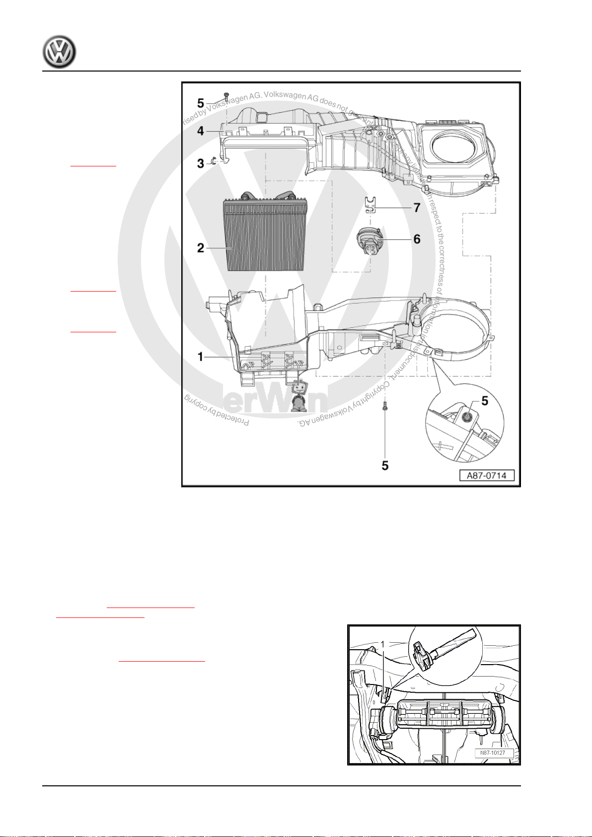
P
r
o
t
e
c
t
e
d
b
y
c
o
p
y
r
i
g
h
t
.
C
o
p
y
i
n
g
f
o
r
p
r
i
v
a
t
e
o
r
c
o
m
m
e
r
c
i
a
l
p
u
r
p
o
s
e
s
,
i
n
p
a
r
t
o
r
i
n
w
h
o
l
e
,
i
s
n
o
t
p
e
r
m
i
t
t
e
d
u
n
l
e
s
s
a
u
t
h
o
r
i
s
e
d
b
y
V
o
l
k
s
w
a
g
e
n
A
G
.
V
o
l
k
s
w
a
g
e
n
A
G
d
o
e
s
n
o
t
g
u
a
r
a
n
t
e
e
o
r
a
c
c
e
p
t
a
n
y
l
i
a
b
i
l
i
t
y
w
i
t
h
r
e
s
p
e
c
t
t
o
t
h
e
c
o
r
r
e
c
t
n
e
s
s
o
f
i
n
f
o
r
m
a
t
i
o
n
i
n
t
h
i
s
d
o
c
u
m
e
n
t
.
C
o
p
y
r
i
g
h
t
b
y
V
o
l
k
s
w
a
g
e
n
A
G
.
Golf Variant 2007 ➤ , Golf Variant 2010 ➤ , Jetta 2005 ➤ , Jetta 2011 ➤
Heating, air conditioning - Edition 04.2010
1 - Evaporator housing - lower
part
2 - Evaporator
❑ Check insulation. It
must be complete.
❑ Removing and installing
⇒ page 99
3 - Clip
4 - Evaporator housing - upper
part
5 - Bolt
6 - Sealing and insulation
❑ Heat insulation for ex‐
pansion valve.
❑ Removing and installing
⇒ page 46
7 - Bracket
❑ Removing and installing
⇒ page 98
3.14 Removing and installing left footwell
vent temperature sender -G261-
3.14.1 Removing
– Remove dash panel ⇒ Rep. gr. 70
– Undo bolts ⇒ Item 10 (page 70) from bracket
⇒ Item 11 (page 71) .
– Pull connector off left footwell vent temperature sender -G261-
-1-.
– Press bracket ⇒ Item 11 (page 71) slightly to left, turn left foot‐
well vent temperature sender -G261- -1- 90° and remove it
from housing.
76 Rep. gr.87 - Air conditioning system
Page 83
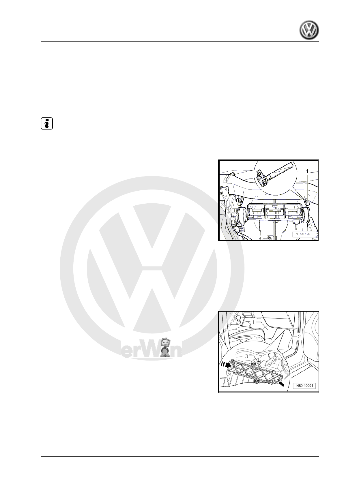
P
r
o
t
e
c
t
e
d
b
y
c
o
p
y
r
i
g
h
t
.
C
o
p
y
i
n
g
f
o
r
p
r
i
v
a
t
e
o
r
c
o
m
m
e
r
c
i
a
l
p
u
r
p
o
s
e
s
,
i
n
p
a
r
t
o
r
i
n
w
h
o
l
e
,
i
s
n
o
t
p
e
r
m
i
t
t
e
d
u
n
l
e
s
s
a
u
t
h
o
r
i
s
e
d
b
y
V
o
l
k
s
w
a
g
e
n
A
G
.
V
o
l
k
s
w
a
g
e
n
A
G
d
o
e
s
n
o
t
g
u
a
r
a
n
t
e
e
o
r
a
c
c
e
p
t
a
n
y
l
i
a
b
i
l
i
t
y
w
i
t
h
r
e
s
p
e
c
t
t
o
t
h
e
c
o
r
r
e
c
t
n
e
s
s
o
f
i
n
f
o
r
m
a
t
i
o
n
i
n
t
h
i
s
d
o
c
u
m
e
n
t
.
C
o
p
y
r
i
g
h
t
b
y
V
o
l
k
s
w
a
g
e
n
A
G
.
Golf Variant 2007 ➤ , Golf Variant 2010 ➤ , Jetta 2005 ➤ , Jetta 2011 ➤
Heating, air conditioning - Edition 04.2010
3.14.2 Installing
Install in reverse order.
3.15 Removing and installing right footwell vent temperature sender -G262-
3.15.1 Removing
Note
For better illustration, right footwell vent temperature sender G262- is shown with dash panel removed. The dash panel need
not be removed.
– Remove glove compartment ⇒ Rep. gr. 68 .
– Pull connector off right footwell vent temperature sender -
G262- -1-.
– Turn right vent temperature sender -G262- -1- 90° and remove
it from housing.
3.15.2 Installing
Install in reverse order.
3.16 Removing and installing evaporator
3.16.1 Removing
– Remove cover -1- in front passenger footwell.
temperature sensor -G308-
3. Climatronic air conditioning with automatic regulation 77
Page 84
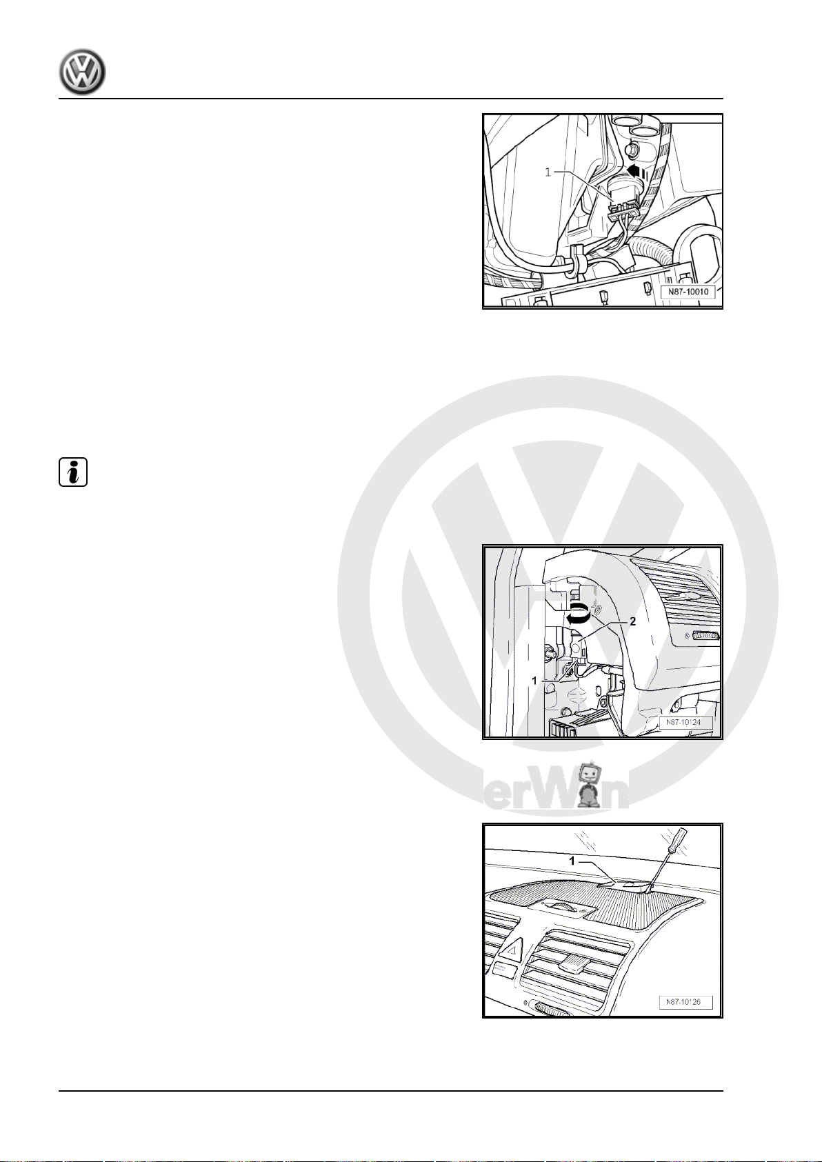
P
r
o
t
e
c
t
e
d
b
y
c
o
p
y
r
i
g
h
t
.
C
o
p
y
i
n
g
f
o
r
p
r
i
v
a
t
e
o
r
c
o
m
m
e
r
c
i
a
l
p
u
r
p
o
s
e
s
,
i
n
p
a
r
t
o
r
i
n
w
h
o
l
e
,
i
s
n
o
t
p
e
r
m
i
t
t
e
d
u
n
l
e
s
s
a
u
t
h
o
r
i
s
e
d
b
y
V
o
l
k
s
w
a
g
e
n
A
G
.
V
o
l
k
s
w
a
g
e
n
A
G
d
o
e
s
n
o
t
g
u
a
r
a
n
t
e
e
o
r
a
c
c
e
p
t
a
n
y
l
i
a
b
i
l
i
t
y
w
i
t
h
r
e
s
p
e
c
t
t
o
t
h
e
c
o
r
r
e
c
t
n
e
s
s
o
f
i
n
f
o
r
m
a
t
i
o
n
i
n
t
h
i
s
d
o
c
u
m
e
n
t
.
C
o
p
y
r
i
g
h
t
b
y
V
o
l
k
s
w
a
g
e
n
A
G
.
Golf Variant 2007 ➤ , Golf Variant 2010 ➤ , Jetta 2005 ➤ , Jetta 2011 ➤
Heating, air conditioning - Edition 04.2010
– Pull connector off evaporator temperature sensor -G308- -1-.
– Turn evaporator temperature sender -G308- in
-direction of arrow- and pull out.
3.16.2 Installing
Install in reverse order.
3.17 Removing left vent temperature sender
-G150- and right vent temperature send‐
er -G151-
Note
Removal of senders on both sides is identical, but one is a mirror
image of the other.
– Remove cover on left or right of dash panel ⇒ Rep. gr. 70 .
– Pull connector -1- off vent temperature sender -2-.
– Turn vent temperature sender -2- 90° in direction of -arrow-
and remove it from dash panel.
3.18 Removing sunlight penetration photo‐
sensor -G107- or sunlight penetration
photosensor 2 -G134-
– Unclip sunlight penetration photosensor -1- out of dash panel
using an appropriate tool.
– Pull connector off sunlight penetration photosensor.
78 Rep. gr.87 - Air conditioning system
Page 85
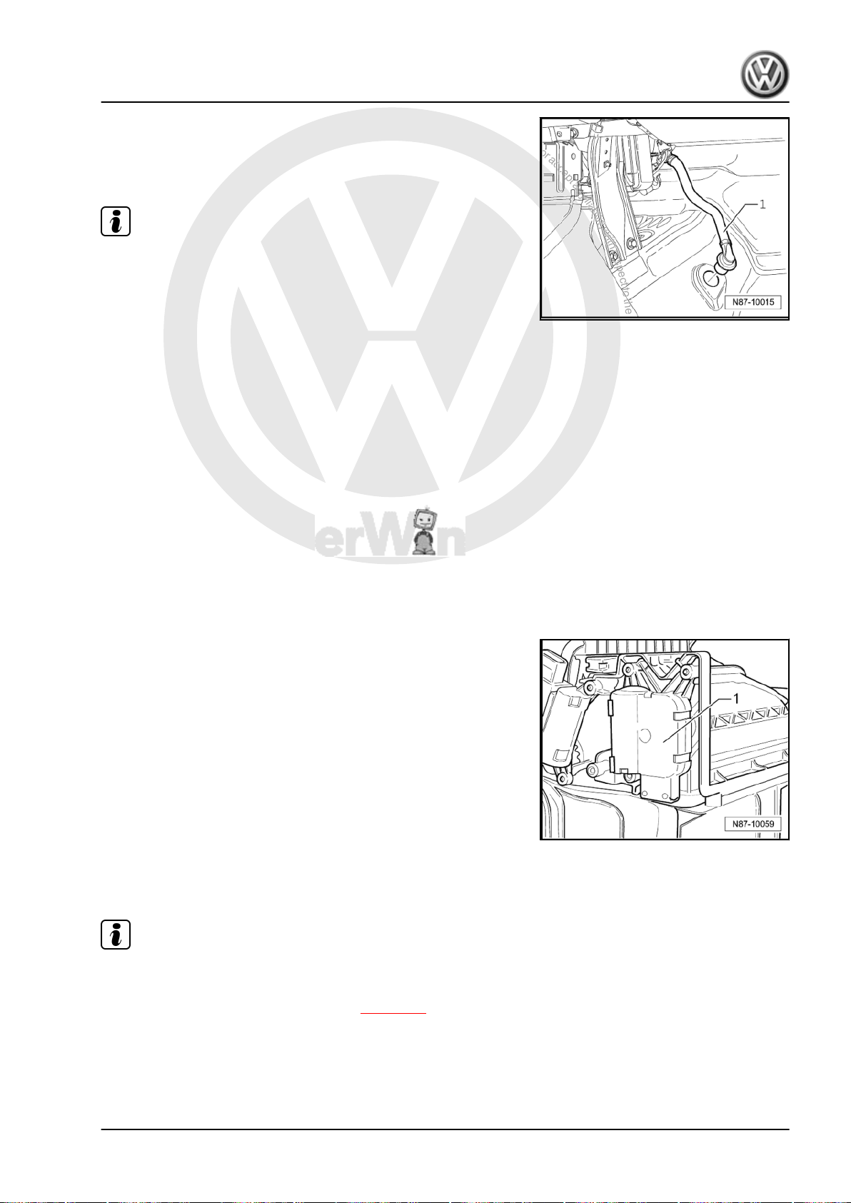
P
r
o
t
e
c
t
e
d
b
y
c
o
p
y
r
i
g
h
t
.
C
o
p
y
i
n
g
f
o
r
p
r
i
v
a
t
e
o
r
c
o
m
m
e
r
c
i
a
l
p
u
r
p
o
s
e
s
,
i
n
p
a
r
t
o
r
i
n
w
h
o
l
e
,
i
s
n
o
t
p
e
r
m
i
t
t
e
d
u
n
l
e
s
s
a
u
t
h
o
r
i
s
e
d
b
y
V
o
l
k
s
w
a
g
e
n
A
G
.
V
o
l
k
s
w
a
g
e
n
A
G
d
o
e
s
n
o
t
g
u
a
r
a
n
t
e
e
o
r
a
c
c
e
p
t
a
n
y
l
i
a
b
i
l
i
t
y
w
i
t
h
r
e
s
p
e
c
t
t
o
t
h
e
c
o
r
r
e
c
t
n
e
s
s
o
f
i
n
f
o
r
m
a
t
i
o
n
i
n
t
h
i
s
d
o
c
u
m
e
n
t
.
C
o
p
y
r
i
g
h
t
b
y
V
o
l
k
s
w
a
g
e
n
A
G
.
Golf Variant 2007 ➤ , Golf Variant 2010 ➤ , Jetta 2005 ➤ , Jetta 2011 ➤
3.19 Checking condensation water drainage hose on heater and air conditioner unit
– Remove footwell cover on front passenger side .
Note
♦
It must be possible to push condensation drain hose -1- onto
the heater and air conditioning unit connection without tension.
♦
The condensation drain hose must be fitted securely to the
connection for condensation drainage of the heater and air
conditioner unit.
3.20 Renewing control motors for air condi‐
First carry out the following work:
– Switch off all electrical consumers.
– Switch off ignition.
– Remove ignition key.
tioning regulation
3.21 Removing and installing fresh air and air recirculation flap control motor -V154-
Heating, air conditioning - Edition 04.2010
3.21.1 Removing
– Remove glove compartment ⇒ Rep. gr. 68 .
– Remove cover for control motors.
– Disconnect connector on fresh air and air recirculation flap
control motor -V154- -1-.
– Separate fresh air and air recirculation flap control motor -
V154- -1-.
3.21.2 Installing
Install in reverse order.
Note
♦
After installation, check operation of air recirculation flap.
♦
Initiate „basic setting“ function using vehicle diagnosis, testing
and information system -VAS 5051B- ⇒ page 55 .
3.22 Removing and installing air flow flap
control motor -V71- or fresh air/recircu‐
3. Climatronic air conditioning with automatic regulation 79
Page 86
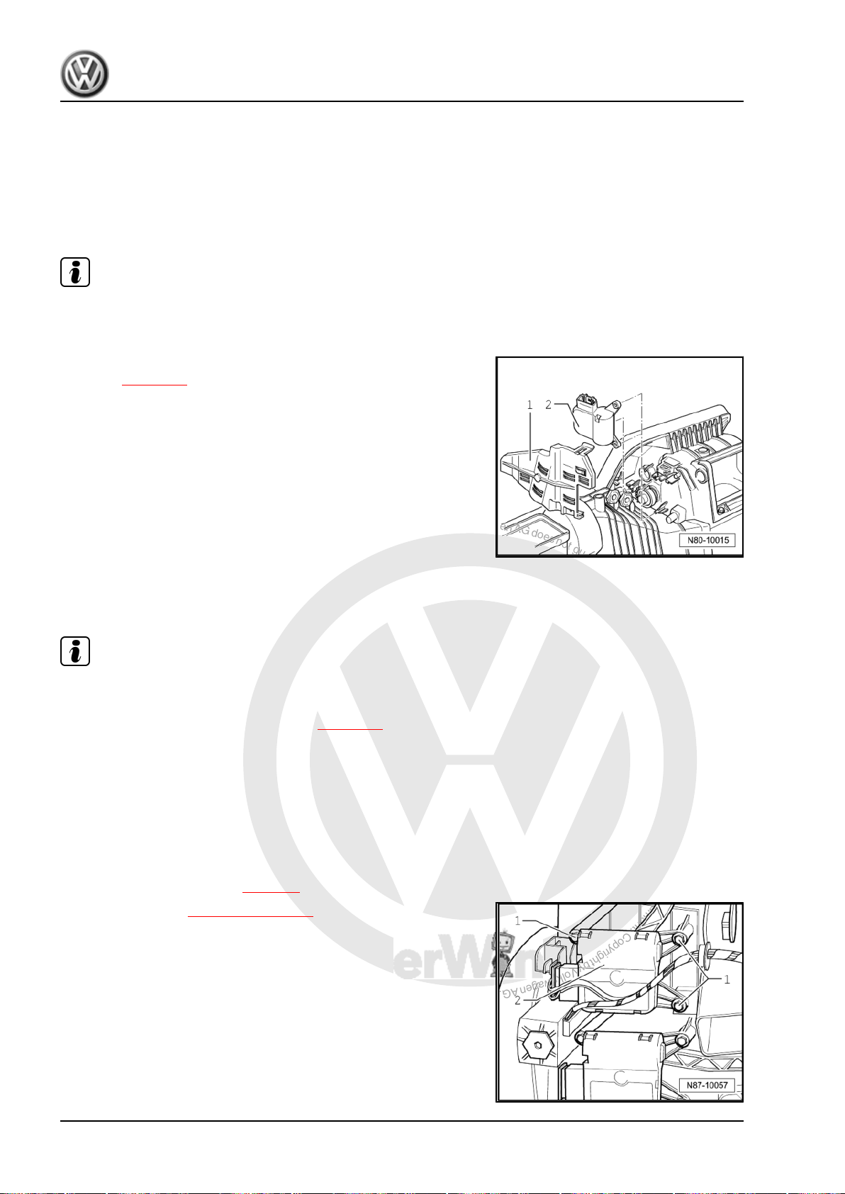
P
r
o
t
e
c
t
e
d
b
y
c
o
p
y
r
i
g
h
t
.
C
o
p
y
i
n
g
f
o
r
p
r
i
v
a
t
e
o
r
c
o
m
m
e
r
c
i
a
l
p
u
r
p
o
s
e
s
,
i
n
p
a
r
t
o
r
i
n
w
h
o
l
e
,
i
s
n
o
t
p
e
r
m
i
t
t
e
d
u
n
l
e
s
s
a
u
t
h
o
r
i
s
e
d
b
y
V
o
l
k
s
w
a
g
e
n
A
G
.
V
o
l
k
s
w
a
g
e
n
A
G
d
o
e
s
n
o
t
g
u
a
r
a
n
t
e
e
o
r
a
c
c
e
p
t
a
n
y
l
i
a
b
i
l
i
t
y
w
i
t
h
r
e
s
p
e
c
t
t
o
t
h
e
c
o
r
r
e
c
t
n
e
s
s
o
f
i
n
f
o
r
m
a
t
i
o
n
i
n
t
h
i
s
d
o
c
u
m
e
n
t
.
C
o
p
y
r
i
g
h
t
b
y
V
o
l
k
s
w
a
g
e
n
A
G
.
Golf Variant 2007 ➤ , Golf Variant 2010 ➤ , Jetta 2005 ➤ , Jetta 2011 ➤
Heating, air conditioning - Edition 04.2010
lated air, air flow flap control motor V425-
3.22.1 Removing
– Remove glove compartment ⇒ Rep. gr. 68 .
Note
The position of the air flow flap must not be changed.
– Remove cover -1-.
– Remove fresh air and air recirculation flap control motor -
V154- ⇒ page 79 .
– Disconnect connector on air flow flap control motor -V71- -2-.
– Pull off air flow flap control motor -V71- -2-.
3.22.2 Installing
Install in reverse order.
Note
♦
After installation, check operation of air flow flap.
♦
Initiate „basic setting“ function using vehicle diagnosis, testing
and information system -VAS 5051B- ⇒ page 55 .
3.23 Removing and installing defroster flap control motor -V107-
3.23.1 Removing
– Remove driver side compartment ⇒ Rep. gr. 68 .
– Remove left footwell vent ⇒ page 9 .
– Remove bracket ⇒ Item 11 (page 71) .
– Disconnect connector on defroster flap control motor -V107-
-2-.
– Remove securing bolts -1- remove defroster flap control motor
-V107- -2- and unhook strut.
80 Rep. gr.87 - Air conditioning system
Page 87
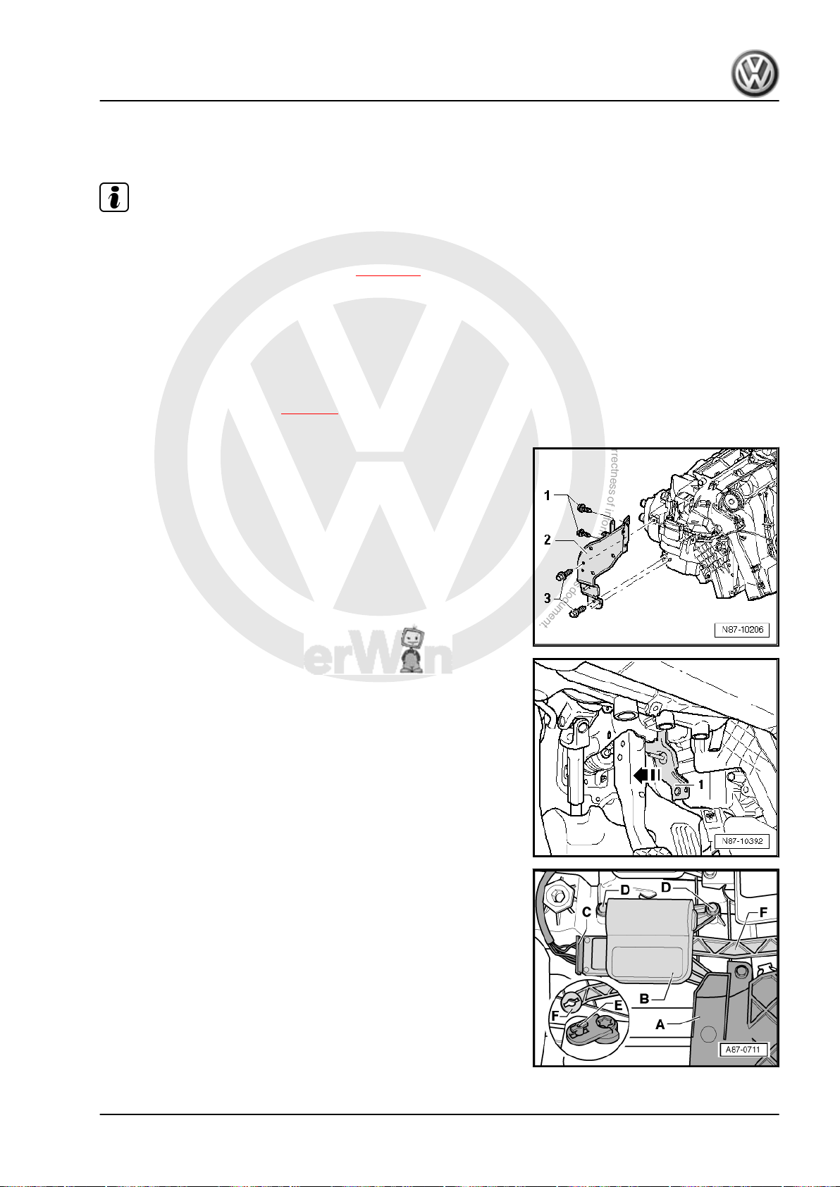
P
r
o
t
e
c
t
e
d
b
y
c
o
p
y
r
i
g
h
t
.
C
o
p
y
i
n
g
f
o
r
p
r
i
v
a
t
e
o
r
c
o
m
m
e
r
c
i
a
l
p
u
r
p
o
s
e
s
,
i
n
p
a
r
t
o
r
i
n
w
h
o
l
e
,
i
s
n
o
t
p
e
r
m
i
t
t
e
d
u
n
l
e
s
s
a
u
t
h
o
r
i
s
e
d
b
y
V
o
l
k
s
w
a
g
e
n
A
G
.
V
o
l
k
s
w
a
g
e
n
A
G
d
o
e
s
n
o
t
g
u
a
r
a
n
t
e
e
o
r
a
c
c
e
p
t
a
n
y
l
i
a
b
i
l
i
t
y
w
i
t
h
r
e
s
p
e
c
t
t
o
t
h
e
c
o
r
r
e
c
t
n
e
s
s
o
f
i
n
f
o
r
m
a
t
i
o
n
i
n
t
h
i
s
d
o
c
u
m
e
n
t
.
C
o
p
y
r
i
g
h
t
b
y
V
o
l
k
s
w
a
g
e
n
A
G
.
Golf Variant 2007 ➤ , Golf Variant 2010 ➤ , Jetta 2005 ➤ , Jetta 2011 ➤
Heating, air conditioning - Edition 04.2010
3.23.2 Installing
Install in reverse order.
Note
♦
After installation, check operation of defroster flap.
♦
Initiate „basic setting“ function using vehicle diagnosis, testing
and information system -VAS 5051B- ⇒ page 55 .
3.24 Removing and installing left tempera‐
3.24.1 Removing
– Remove left footwell vent ⇒ page 9 .
– Remove centre console trim from left footwell.
– Remove data bus diagnosis interface -J533- ⇒ Rep. gr. 97 .
– Remove bolts -3- (9 ± 1.3 Nm).
– Do not remove bolts -1-.
– Do not remove bracket -2-.
ture flap control motor -V158-
– Press bracket -1- in direction of brake pedal and secure it there
with a cable tie.
– Mark connector -C- to control motor (danger of interchanging
with other connectors of same construction).
– Disconnect connector -C- on left temperature flap control mo‐
tor -V158- .
– Remove cover -A-.
– Undo securing bolts -D- (1.4 Nm) and remove left temperature
flap control motor -V158- -B-.
– Release control motor lever -E- from connecting rod -F-.
3. Climatronic air conditioning with automatic regulation 81
Page 88
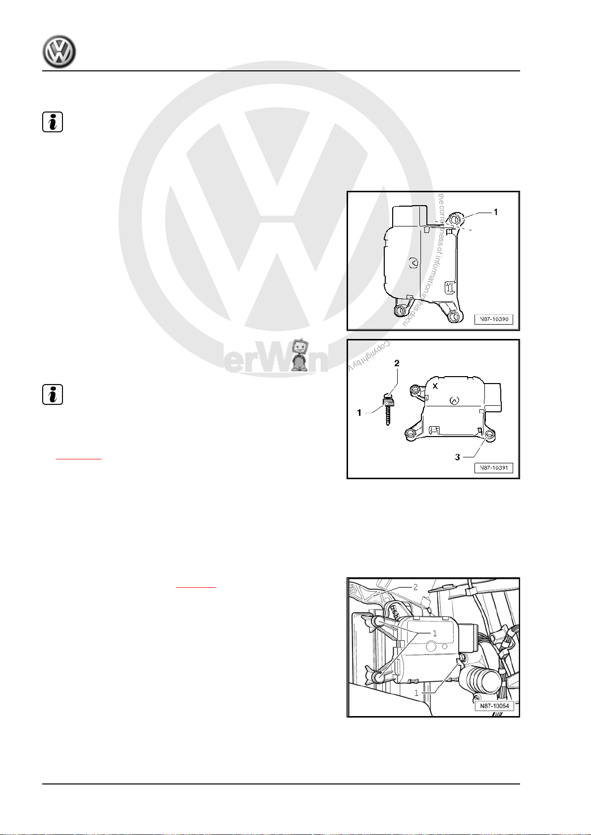
P
r
o
t
e
c
t
e
d
b
y
c
o
p
y
r
i
g
h
t
.
C
o
p
y
i
n
g
f
o
r
p
r
i
v
a
t
e
o
r
c
o
m
m
e
r
c
i
a
l
p
u
r
p
o
s
e
s
,
i
n
p
a
r
t
o
r
i
n
w
h
o
l
e
,
i
s
n
o
t
p
e
r
m
i
t
t
e
d
u
n
l
e
s
s
a
u
t
h
o
r
i
s
e
d
b
y
V
o
l
k
s
w
a
g
e
n
A
G
.
V
o
l
k
s
w
a
g
e
n
A
G
d
o
e
s
n
o
t
g
u
a
r
a
n
t
e
e
o
r
a
c
c
e
p
t
a
n
y
l
i
a
b
i
l
i
t
y
w
i
t
h
r
e
s
p
e
c
t
t
o
t
h
e
c
o
r
r
e
c
t
n
e
s
s
o
f
i
n
f
o
r
m
a
t
i
o
n
i
n
t
h
i
s
d
o
c
u
m
e
n
t
.
C
o
p
y
r
i
g
h
t
b
y
V
o
l
k
s
w
a
g
e
n
A
G
.
Golf Variant 2007 ➤ , Golf Variant 2010 ➤ , Jetta 2005 ➤ , Jetta 2011 ➤
Heating, air conditioning - Edition 04.2010
3.24.2 Installing
Note
Optimised control motors are marked with an „X“.
To ease assembly, use a ≈ 2 mm shorter oval-head bolt -N 103
254 01- .
– Separate bracket -1- from old left temperature flap control mo‐
tor -V158- , e.g. using side cutting pliers.
– Position new left temperature flap control motor -V158- ,
marked with an „X“, with shortened oval-head screw -2- and
cut-off bracket -1- on bracket -3- on blower box.
Note
♦
After installation, check operation of left temperature flap.
♦
Initiate „basic settings“ function using vehicle diagnosis, test‐
ing and information system -VAS 5051- or successor model
⇒ page 55 .
3.25 Removing and installing right tempera‐
ture flap control motor -V159-
3.25.1 Removing
– Remove glove compartment ⇒ Rep. gr. 68 .
– Remove right footwell vent ⇒ page 9 .
– Disconnect connector on right temperature flap control motor
-V159- .
– Remove securing bolts -1- and remove right temperature flap
control motor -V159- .
– Unhook lever -2- from right temperature flap control motor -
V159- .
3.25.2 Installing
Install in reverse order.
82 Rep. gr.87 - Air conditioning system
Page 89
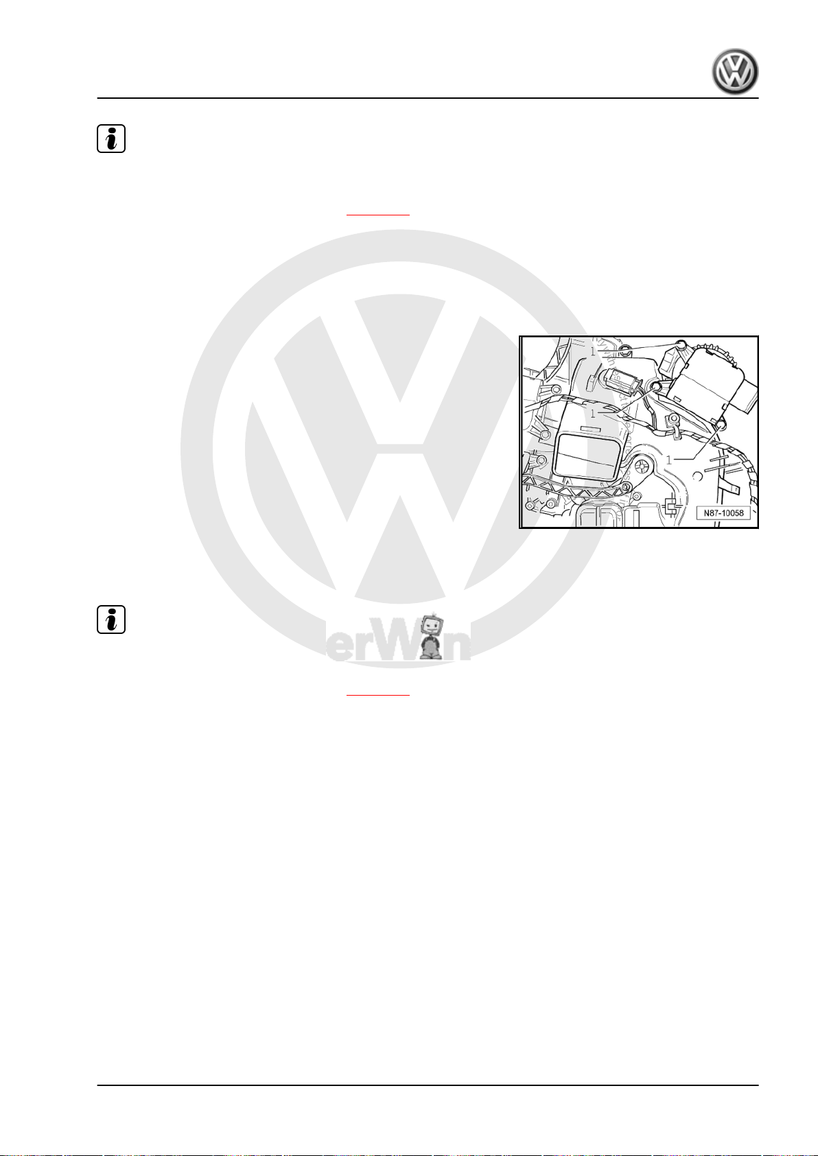
P
r
o
t
e
c
t
e
d
b
y
c
o
p
y
r
i
g
h
t
.
C
o
p
y
i
n
g
f
o
r
p
r
i
v
a
t
e
o
r
c
o
m
m
e
r
c
i
a
l
p
u
r
p
o
s
e
s
,
i
n
p
a
r
t
o
r
i
n
w
h
o
l
e
,
i
s
n
o
t
p
e
r
m
i
t
t
e
d
u
n
l
e
s
s
a
u
t
h
o
r
i
s
e
d
b
y
V
o
l
k
s
w
a
g
e
n
A
G
.
V
o
l
k
s
w
a
g
e
n
A
G
d
o
e
s
n
o
t
g
u
a
r
a
n
t
e
e
o
r
a
c
c
e
p
t
a
n
y
l
i
a
b
i
l
i
t
y
w
i
t
h
r
e
s
p
e
c
t
t
o
t
h
e
c
o
r
r
e
c
t
n
e
s
s
o
f
i
n
f
o
r
m
a
t
i
o
n
i
n
t
h
i
s
d
o
c
u
m
e
n
t
.
C
o
p
y
r
i
g
h
t
b
y
V
o
l
k
s
w
a
g
e
n
A
G
.
Golf Variant 2007 ➤ , Golf Variant 2010 ➤ , Jetta 2005 ➤ , Jetta 2011 ➤
Heating, air conditioning - Edition 04.2010
Note
♦
After installation, check operation of right temperature flap.
♦
Initiate „basic setting“ function using vehicle diagnosis, testing
and information system -VAS 5051B- ⇒ page 55 .
3.26 Removing and installing central flap control motor -V70-
3.26.1 Removing
– Remove dash panel. ⇒ Rep. gr. 70
– Disconnect connector on centre flap control motor -V70- .
– Remove securing bolts -1- and remove central flap control
motor -V70- .
3.26.2 Installing
Install in reverse order.
Note
♦
After installation, check operation of central flap.
♦
Initiate „basic setting“ function using vehicle diagnosis, testing
and information system -VAS 5051B- ⇒ page 55 .
3. Climatronic air conditioning with automatic regulation 83
Page 90
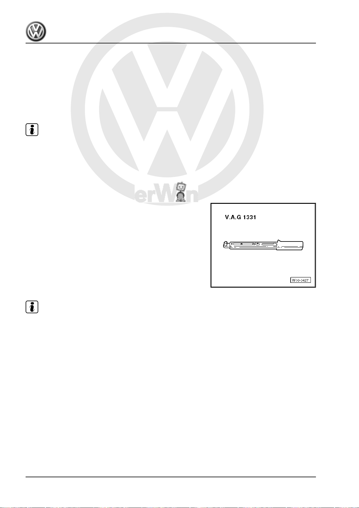
P
r
o
t
e
c
t
e
d
b
y
c
o
p
y
r
i
g
h
t
.
C
o
p
y
i
n
g
f
o
r
p
r
i
v
a
t
e
o
r
c
o
m
m
e
r
c
i
a
l
p
u
r
p
o
s
e
s
,
i
n
p
a
r
t
o
r
i
n
w
h
o
l
e
,
i
s
n
o
t
p
e
r
m
i
t
t
e
d
u
n
l
e
s
s
a
u
t
h
o
r
i
s
e
d
b
y
V
o
l
k
s
w
a
g
e
n
A
G
.
V
o
l
k
s
w
a
g
e
n
A
G
d
o
e
s
n
o
t
g
u
a
r
a
n
t
e
e
o
r
a
c
c
e
p
t
a
n
y
l
i
a
b
i
l
i
t
y
w
i
t
h
r
e
s
p
e
c
t
t
o
t
h
e
c
o
r
r
e
c
t
n
e
s
s
o
f
i
n
f
o
r
m
a
t
i
o
n
i
n
t
h
i
s
d
o
c
u
m
e
n
t
.
C
o
p
y
r
i
g
h
t
b
y
V
o
l
k
s
w
a
g
e
n
A
G
.
Golf Variant 2007 ➤ , Golf Variant 2010 ➤ , Jetta 2005 ➤ , Jetta 2011 ➤
Heating, air conditioning - Edition 04.2010
4 Ancillary bracket for air conditioner
compressor
4.1 Removing and installing ancillary brack‐
Note
The removal of ancillary bracket for Jetta 2011► is described in
⇒ Rep. gr. 13 .
4.2 Removing and installing ancillary brack‐
Special tools and workshop equipment required
♦ Torque wrench -V.A.G 1331/- (5…50 Nm)
et for air conditioner compressor (Jetta
2011►)
et for air conditioner compressor, engine
codes BRM and BXE
Note
♦
The ancillary bracket for air conditioner compressor and rela‐
ted components can be removed and installed without the
refrigerant circuit being opened.
♦
To remove poly V-belt ⇒ Rep. gr. 13 .
84 Rep. gr.87 - Air conditioning system
Page 91
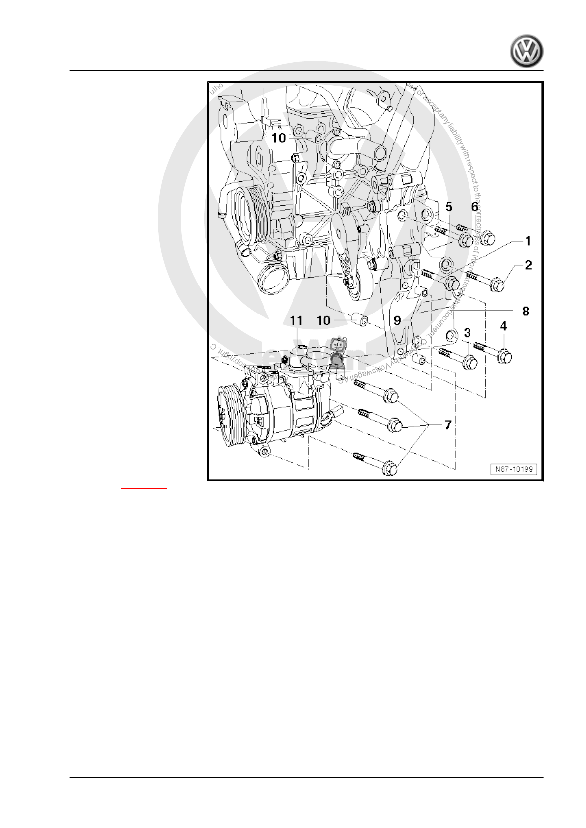
P
r
o
t
e
c
t
e
d
b
y
c
o
p
y
r
i
g
h
t
.
C
o
p
y
i
n
g
f
o
r
p
r
i
v
a
t
e
o
r
c
o
m
m
e
r
c
i
a
l
p
u
r
p
o
s
e
s
,
i
n
p
a
r
t
o
r
i
n
w
h
o
l
e
,
i
s
n
o
t
p
e
r
m
i
t
t
e
d
u
n
l
e
s
s
a
u
t
h
o
r
i
s
e
d
b
y
V
o
l
k
s
w
a
g
e
n
A
G
.
V
o
l
k
s
w
a
g
e
n
A
G
d
o
e
s
n
o
t
g
u
a
r
a
n
t
e
e
o
r
a
c
c
e
p
t
a
n
y
l
i
a
b
i
l
i
t
y
w
i
t
h
r
e
s
p
e
c
t
t
o
t
h
e
c
o
r
r
e
c
t
n
e
s
s
o
f
i
n
f
o
r
m
a
t
i
o
n
i
n
t
h
i
s
d
o
c
u
m
e
n
t
.
C
o
p
y
r
i
g
h
t
b
y
V
o
l
k
s
w
a
g
e
n
A
G
.
Golf Variant 2007 ➤ , Golf Variant 2010 ➤ , Jetta 2005 ➤ , Jetta 2011 ➤
1 - Hexagon bolt M10×65
❑ 50 Nm
2 - Hexagon bolt M10×45
❑ 50 Nm
3 - Hexagon bolt M10×45
❑ 50 Nm
4 - Hexagon bolt M10x45
❑ 50 Nm
5 - Hexagon bolt M10×65
❑ 50 Nm
6 - Hexagon bolt M10×65
❑ 50 Nm
7 - Hexagon bolt M8x100
❑ Qty. 3
❑ 25 Nm
8 - Ancillary bracket for alter‐
nator and air conditioner com‐
pressor
♦ Number on ancillary brack‐
et -03G 903 143 A-
Removing
Heating, air conditioning - Edition 04.2010
– Remove alternator ⇒
Rep. gr. 27 .
– Loosen air conditioner
compressor and re‐
move hexagon bolt -7-.
Remove air conditioner
compressor from ancil‐
lary bracket and secure
to body with suitable
material (e.g. uncoated
wire) ⇒ page 86 .
– Remove bolts -1- to -6- and remove ancillary bracket from cylinder block.
♦ Strictly observe tightening sequence of securing bolts:
– Tighten hexagon bolts position -1-, -2-, -3-, -4-, -5- and -6- one after the other.
9 - Dowel sleeves
❑ Qty. 2
❑ Ensure proper seating between ancillary bracket and air conditioner compressor.
10 - Dowel sleeves
❑ Qty. 2
❑ Ensure proper seating between ancillary bracket and cylinder block.
11 - Air conditioner compressor
❑ Removing and installing ⇒ page 96
4. Ancillary bracket for air conditioner compressor 85
Page 92
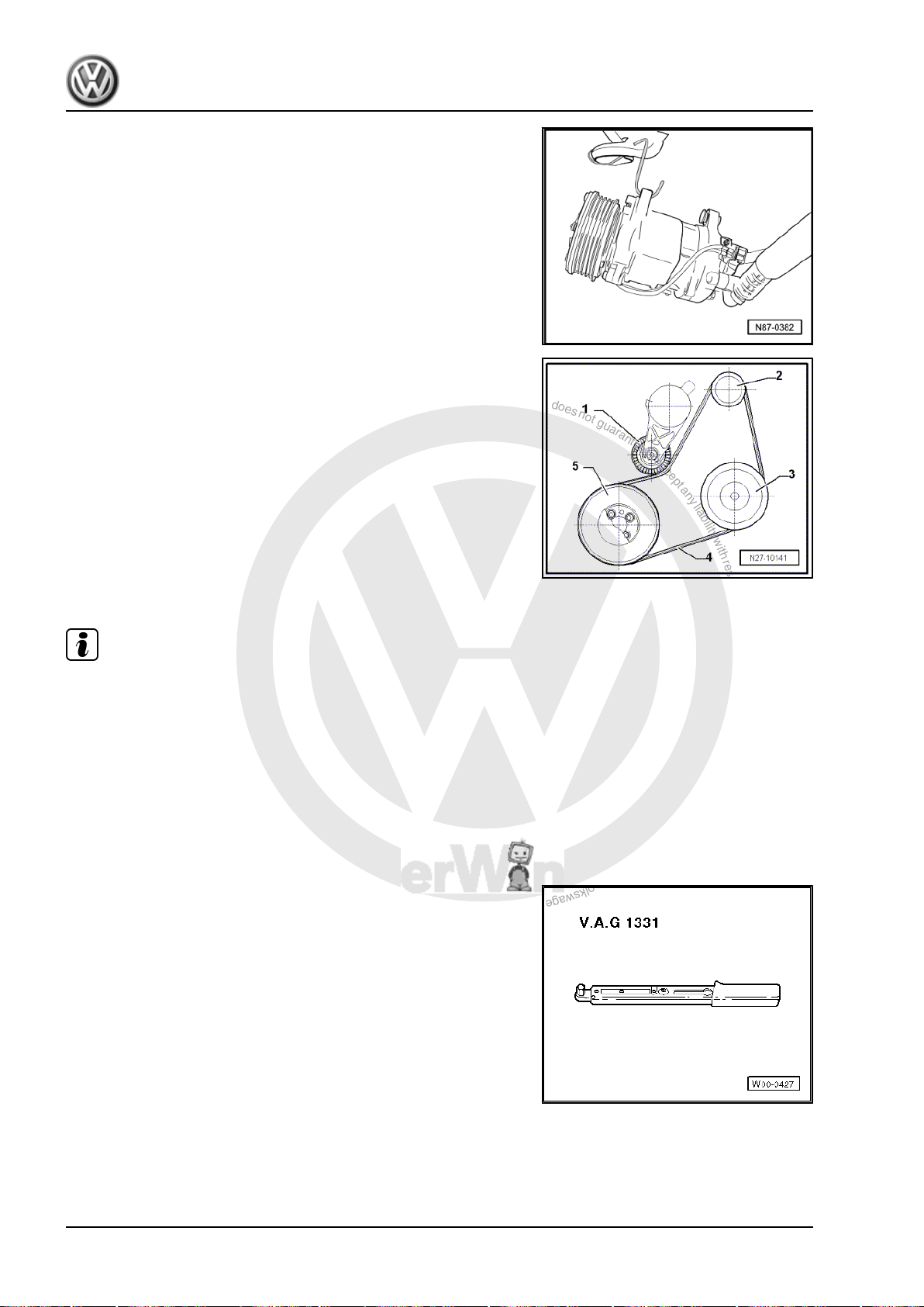
P
r
o
t
e
c
t
e
d
b
y
c
o
p
y
r
i
g
h
t
.
C
o
p
y
i
n
g
f
o
r
p
r
i
v
a
t
e
o
r
c
o
m
m
e
r
c
i
a
l
p
u
r
p
o
s
e
s
,
i
n
p
a
r
t
o
r
i
n
w
h
o
l
e
,
i
s
n
o
t
p
e
r
m
i
t
t
e
d
u
n
l
e
s
s
a
u
t
h
o
r
i
s
e
d
b
y
V
o
l
k
s
w
a
g
e
n
A
G
.
V
o
l
k
s
w
a
g
e
n
A
G
d
o
e
s
n
o
t
g
u
a
r
a
n
t
e
e
o
r
a
c
c
e
p
t
a
n
y
l
i
a
b
i
l
i
t
y
w
i
t
h
r
e
s
p
e
c
t
t
o
t
h
e
c
o
r
r
e
c
t
n
e
s
s
o
f
i
n
f
o
r
m
a
t
i
o
n
i
n
t
h
i
s
d
o
c
u
m
e
n
t
.
C
o
p
y
r
i
g
h
t
b
y
V
o
l
k
s
w
a
g
e
n
A
G
.
Golf Variant 2007 ➤ , Golf Variant 2010 ➤ , Jetta 2005 ➤ , Jetta 2011 ➤
Heating, air conditioning - Edition 04.2010
Securing air conditioner compressor to body
Poly V-belt routing
1 - Tensioning roller
2 - Poly V-belt pulley for alternator
3 - Poly V-belt pulley for air conditioner compressor
4 - Poly V-belt
5 - Poly V-belt pulley for crankshaft
If compressor is removed without opening refrigerant circuit, it
should be secured to body using suitable material, for example,
welding wire.
When doing this, ensure refrigerant hoses on air conditioner com‐
pressor are not stressed.
Note
♦
When installing poly V-belt, ensure that it is correctly seated
on poly V-belt pulley.
♦
Finally, place poly V-belt over pulley of air conditioner com‐
pressor.
4.3 Removing and installing ancillary brack‐
et for air conditioner compressor, engine
codes BGP and BGQ
Special tools and workshop equipment required
♦ Torque wrench -V.A.G 1331/- (5…50 Nm)
86 Rep. gr.87 - Air conditioning system
Page 93
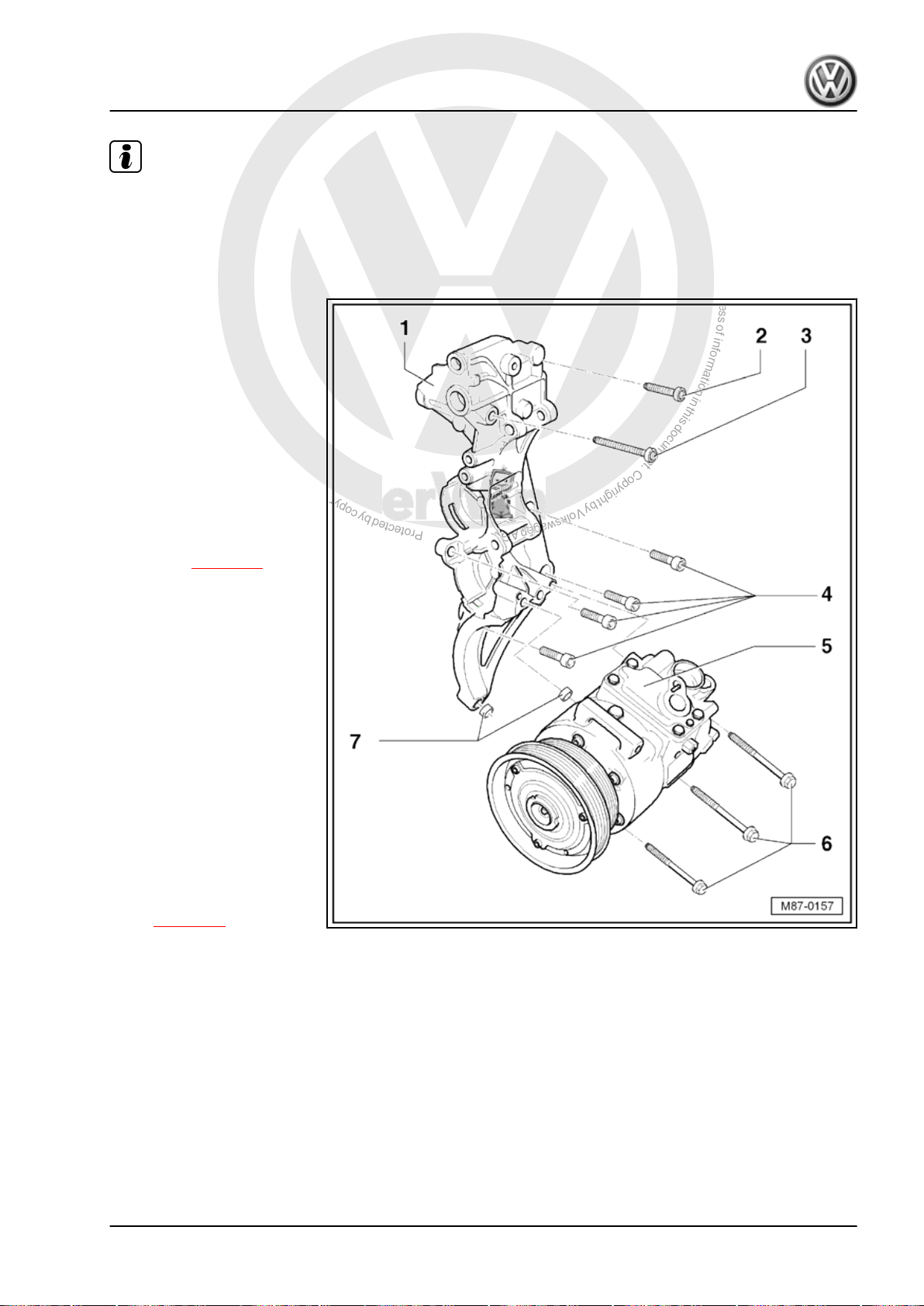
P
r
o
t
e
c
t
e
d
b
y
c
o
p
y
r
i
g
h
t
.
C
o
p
y
i
n
g
f
o
r
p
r
i
v
a
t
e
o
r
c
o
m
m
e
r
c
i
a
l
p
u
r
p
o
s
e
s
,
i
n
p
a
r
t
o
r
i
n
w
h
o
l
e
,
i
s
n
o
t
p
e
r
m
i
t
t
e
d
u
n
l
e
s
s
a
u
t
h
o
r
i
s
e
d
b
y
V
o
l
k
s
w
a
g
e
n
A
G
.
V
o
l
k
s
w
a
g
e
n
A
G
d
o
e
s
n
o
t
g
u
a
r
a
n
t
e
e
o
r
a
c
c
e
p
t
a
n
y
l
i
a
b
i
l
i
t
y
w
i
t
h
r
e
s
p
e
c
t
t
o
t
h
e
c
o
r
r
e
c
t
n
e
s
s
o
f
i
n
f
o
r
m
a
t
i
o
n
i
n
t
h
i
s
d
o
c
u
m
e
n
t
.
C
o
p
y
r
i
g
h
t
b
y
V
o
l
k
s
w
a
g
e
n
A
G
.
Golf Variant 2007 ➤ , Golf Variant 2010 ➤ , Jetta 2005 ➤ , Jetta 2011 ➤
Note
♦
The ancillary bracket for air conditioner compressor and rela‐
ted components can be removed and installed without the
refrigerant circuit being opened.
♦
To remove poly V-belt ⇒ Rep. gr. 13 .
1 - Ancillary bracket for alter‐
nator and air conditioner com‐
pressor
♦ Number on ancillary brack‐
et -07K 903 143 B-
Removing
– Loosen air conditioner
compressor and re‐
move hexagon bolt -6-.
Remove air conditioner
compressor from ancil‐
lary bracket and secure
to body with suitable
material (e.g. uncoated
wire) ⇒ page 88 .
– Undo bolts -2, 3 and 4-
Heating, air conditioning - Edition 04.2010
and remove ancillary
bracket -1- from cylinder
block.
2 - Multi-point socket head bolt
M8x60
❑ 25 Nm
3 - Multi-point socket head bolt
M8x110
❑ 25 Nm
4 - Hexagon socket head bolt
M8x30
❑ 25 Nm
❑ Qty. 4
5 - Air conditioner compressor
❑ Removing and installing
⇒ page 96
6 - Hexagon bolts M8x85
❑ 25 Nm
❑ Qty. 3
7 - Dowel sleeves
❑ Qty. 2
❑ Ensure proper seating between ancillary bracket and air conditioner compressor.
4. Ancillary bracket for air conditioner compressor 87
Page 94
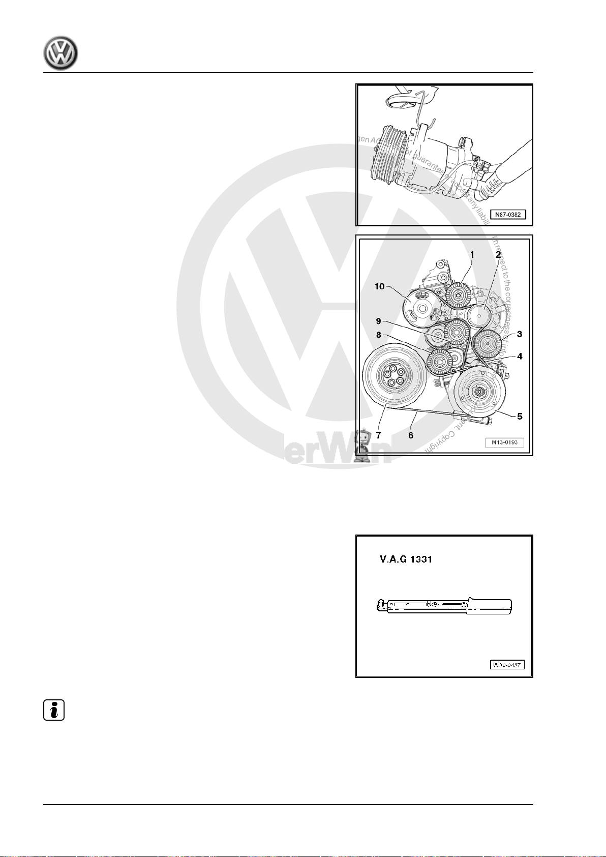
P
r
o
t
e
c
t
e
d
b
y
c
o
p
y
r
i
g
h
t
.
C
o
p
y
i
n
g
f
o
r
p
r
i
v
a
t
e
o
r
c
o
m
m
e
r
c
i
a
l
p
u
r
p
o
s
e
s
,
i
n
p
a
r
t
o
r
i
n
w
h
o
l
e
,
i
s
n
o
t
p
e
r
m
i
t
t
e
d
u
n
l
e
s
s
a
u
t
h
o
r
i
s
e
d
b
y
V
o
l
k
s
w
a
g
e
n
A
G
.
V
o
l
k
s
w
a
g
e
n
A
G
d
o
e
s
n
o
t
g
u
a
r
a
n
t
e
e
o
r
a
c
c
e
p
t
a
n
y
l
i
a
b
i
l
i
t
y
w
i
t
h
r
e
s
p
e
c
t
t
o
t
h
e
c
o
r
r
e
c
t
n
e
s
s
o
f
i
n
f
o
r
m
a
t
i
o
n
i
n
t
h
i
s
d
o
c
u
m
e
n
t
.
C
o
p
y
r
i
g
h
t
b
y
V
o
l
k
s
w
a
g
e
n
A
G
.
Golf Variant 2007 ➤ , Golf Variant 2010 ➤ , Jetta 2005 ➤ , Jetta 2011 ➤
Heating, air conditioning - Edition 04.2010
Securing air conditioner compressor to body
Poly V-belt routing
1 - Upper idler pulley
2 - Pulley - Alternator
3 - Lower idler pulley
4 - Poly V-belt for alternator and coolant pump
5 - Pulley - Air conditioner compressor
6 - Poly V-belt for air conditioner compressor
7 - Pulley - Crankshaft
8 - Tensioning roller for air conditioner compressor poly V-belt
9 - Tensioning roller for poly V-belt for alternator and coolant
pump
10 - Coolant pump pulley
4.4 Removing and installing ancillary brack‐
et for air conditioner compressor, engine
codes BPY, BWA, BSE, BSF, BLR, BLY
Special tools and workshop equipment required
♦ Torque wrench -V.A.G 1331/- (5…50 Nm)
Note
♦
The ancillary bracket for air conditioner compressor and related components can be removed and installed
without the refrigerant circuit being opened.
♦
To remove poly V-belt ⇒ Rep. gr. 13 .
88 Rep. gr.87 - Air conditioning system
Page 95
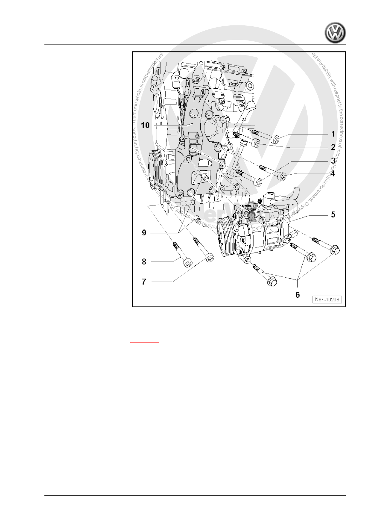
P
r
o
t
e
c
t
e
d
b
y
c
o
p
y
r
i
g
h
t
.
C
o
p
y
i
n
g
f
o
r
p
r
i
v
a
t
e
o
r
c
o
m
m
e
r
c
i
a
l
p
u
r
p
o
s
e
s
,
i
n
p
a
r
t
o
r
i
n
w
h
o
l
e
,
i
s
n
o
t
p
e
r
m
i
t
t
e
d
u
n
l
e
s
s
a
u
t
h
o
r
i
s
e
d
b
y
V
o
l
k
s
w
a
g
e
n
A
G
.
V
o
l
k
s
w
a
g
e
n
A
G
d
o
e
s
n
o
t
g
u
a
r
a
n
t
e
e
o
r
a
c
c
e
p
t
a
n
y
l
i
a
b
i
l
i
t
y
w
i
t
h
r
e
s
p
e
c
t
t
o
t
h
e
c
o
r
r
e
c
t
n
e
s
s
o
f
i
n
f
o
r
m
a
t
i
o
n
i
n
t
h
i
s
d
o
c
u
m
e
n
t
.
C
o
p
y
r
i
g
h
t
b
y
V
o
l
k
s
w
a
g
e
n
A
G
.
1 - Socket head flange bolt
M10×45
❑ Dowel hole
❑ Observe different tor‐
ques:
❑ 1.6 l injection engine
and 2.0 l FSI engine:
52 Nm
❑ 2.0 l turbo FSI engine:
40 Nm
2 - Socket head flange bolt
M10×45
❑ Observe different tor‐
ques:
❑ 1.6 l injection engine
and 2.0 l FSI engine:
52 Nm
❑ 2.0 l turbo FSI engine:
40 Nm
3 - Socket head flange bolt
M10×45
❑ Observe different tor‐
ques:
❑ 1.6 l injection engine
and 2.0 l FSI engine:
Golf Variant 2007 ➤ , Golf Variant 2010 ➤ , Jetta 2005 ➤ , Jetta 2011 ➤
52 Nm
❑ 2.0 l turbo FSI engine:
40 Nm
4 - Socket head flange bolt
M10×45
❑ Observe different tor‐
ques:
❑ 1.6 l injection engine
and 2.0 l FSI engine:
52 Nm
❑ 2.0 l turbo FSI engine: 40 Nm
5 - Air conditioner compressor
❑ Removing and installing ⇒ page 96
6 - Hexagon bolt M8x100
❑ Qty. 3
❑ 25 Nm
7 - Socket head flange bolt M10×45
❑ Dowel hole
❑ Observe different torques:
❑ 1.6 l injection engine and 2.0 l FSI engine: 52 Nm
❑ 2.0 l turbo FSI engine: 40 Nm
Heating, air conditioning - Edition 04.2010
8 - Socket head flange bolt M10×45
❑ Observe different torques:
❑ 1.6 l injection engine and 2.0 l FSI engine: 52 Nm
❑ 2.0 l turbo FSI engine: 40 Nm
9 - Dowel sleeves
❑ Qty. 2
❑ Ensure proper seating between ancillary bracket and air conditioner compressor.
4. Ancillary bracket for air conditioner compressor 89
Page 96
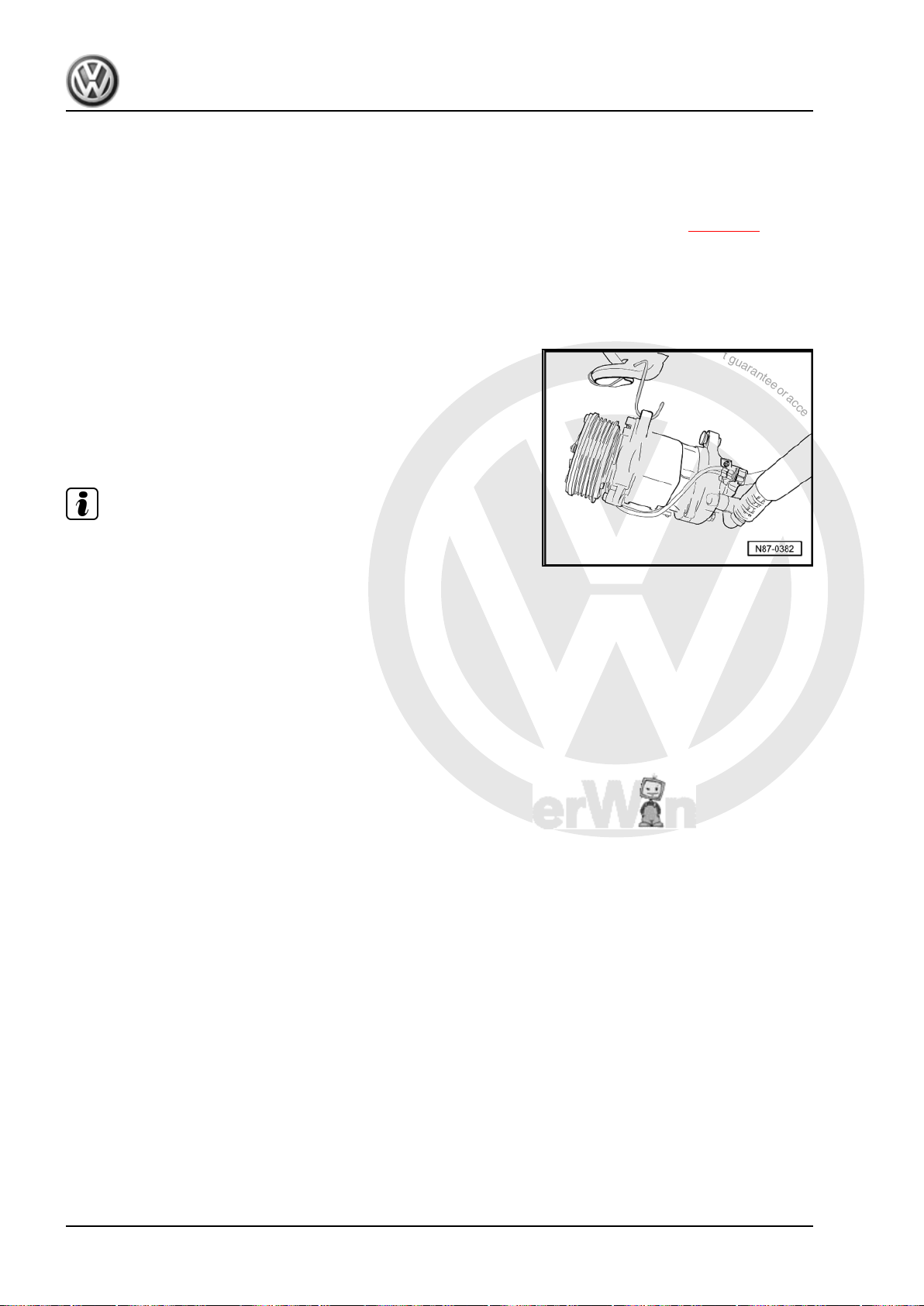
P
r
o
t
e
c
t
e
d
b
y
c
o
p
y
r
i
g
h
t
.
C
o
p
y
i
n
g
f
o
r
p
r
i
v
a
t
e
o
r
c
o
m
m
e
r
c
i
a
l
p
u
r
p
o
s
e
s
,
i
n
p
a
r
t
o
r
i
n
w
h
o
l
e
,
i
s
n
o
t
p
e
r
m
i
t
t
e
d
u
n
l
e
s
s
a
u
t
h
o
r
i
s
e
d
b
y
V
o
l
k
s
w
a
g
e
n
A
G
.
V
o
l
k
s
w
a
g
e
n
A
G
d
o
e
s
n
o
t
g
u
a
r
a
n
t
e
e
o
r
a
c
c
e
p
t
a
n
y
l
i
a
b
i
l
i
t
y
w
i
t
h
r
e
s
p
e
c
t
t
o
t
h
e
c
o
r
r
e
c
t
n
e
s
s
o
f
i
n
f
o
r
m
a
t
i
o
n
i
n
t
h
i
s
d
o
c
u
m
e
n
t
.
C
o
p
y
r
i
g
h
t
b
y
V
o
l
k
s
w
a
g
e
n
A
G
.
Golf Variant 2007 ➤ , Golf Variant 2010 ➤ , Jetta 2005 ➤ , Jetta 2011 ➤
Heating, air conditioning - Edition 04.2010
10 - Ancillary bracket for air conditioner compressor
Number on ancillary bracket -06F 903 143 E/FRemoving
– Remove alternator ⇒ Rep. gr. 27 .
– Loosen air conditioner compressor and remove hexagon bolt -6-. Remove air conditioner compressor
from ancillary bracket and secure to body with suitable material (e.g. uncoated wire) ⇒ page 90 .
– Remove bolts -1- to -4-, -7- and -8- and remove ancillary bracket -10- from cylinder block.
Installing
♦ Strictly observe tightening sequence of securing bolts:
– Tighten socket head flange bolts, positions -1- (dowel hole), -7- (dowel hole), -4-, -8-, -3- and -2- one
after the other.
Securing air conditioner compressor to body
If compressor is removed without opening refrigerant circuit, it
should be secured to body using suitable material, for example,
welding wire.
When doing this, ensure refrigerant hoses on air conditioner com‐
pressor are not stressed.
Note
♦
When installing poly V-belt, ensure that it is correctly seated
on poly V-belt pulley.
♦
Finally, place poly V-belt over pulley of air conditioner com‐
pressor.
90 Rep. gr.87 - Air conditioning system
Page 97
P
r
o
t
e
c
t
e
d
b
y
c
o
p
y
r
i
g
h
t
.
C
o
p
y
i
n
g
f
o
r
p
r
i
v
a
t
e
o
r
c
o
m
m
e
r
c
i
a
l
p
u
r
p
o
s
e
s
,
i
n
p
a
r
t
o
r
i
n
w
h
o
l
e
,
i
s
n
o
t
p
e
r
m
i
t
t
e
d
u
n
l
e
s
s
a
u
t
h
o
r
i
s
e
d
b
y
V
o
l
k
s
w
a
g
e
n
A
G
.
V
o
l
k
s
w
a
g
e
n
A
G
d
o
e
s
n
o
t
g
u
a
r
a
n
t
e
e
o
r
a
c
c
e
p
t
a
n
y
l
i
a
b
i
l
i
t
y
w
i
t
h
r
e
s
p
e
c
t
t
o
t
h
e
c
o
r
r
e
c
t
n
e
s
s
o
f
i
n
f
o
r
m
a
t
i
o
n
i
n
t
h
i
s
d
o
c
u
m
e
n
t
.
C
o
p
y
r
i
g
h
t
b
y
V
o
l
k
s
w
a
g
e
n
A
G
.
Golf Variant 2007 ➤ , Golf Variant 2010 ➤ , Jetta 2005 ➤ , Jetta 2011 ➤
Heating, air conditioning - Edition 04.2010
5 Repair work on refrigerant circuit
which may be performed only in ap‐
propriate workshops by specially
trained mechanics
Special tools and workshop equipment required
♦ Notes on repair work to vehicles with air conditioning and on
handling refrigerant can be found in ELSA under repair group
⇒ Rep. gr. 00 Technical information „Air conditioning system
- with refrigerant R134a VW“.
♦ Notes on tools for repair work to vehicles with air conditioning
can be found in ELSA under repair group ⇒ Rep. gr. 00
Technical information „Air conditioning system - with refriger‐
ant R134a VW“.
♦ The version in ELSA under the Internet button is no longer
valid.
Note
♦
The refrigerant must be extracted beforehand, e.g. with air
conditioner service station -VAS 6007A- .
♦
The previously used air conditioner service stations can still
be used ⇒ Volkswagen Workshop Equipment catalogue.
♦
To prevent the intrusion of moisture, all components of the re‐
frigerant circuit which have been opened must be sealed with
suitable plugs.
♦
The colour coding of O-rings for R134a refrigerant circuits has
been discontinued. Coloured and black O-rings are used.
♦
Coat threaded connections of refrigerant circuit with polyethy‐
lene glycol (PEG) VW part number 294440 before installation.
♦
Under certain conditions, it is no longer necessary to renew
the receiver with dryer cartridge each time the refrigerant cir‐
cuit is opened ⇒ Rep. gr. 00 Technical information „Air
conditioning systems - with refrigerant R134a VW“ Renewing
parts.
5.1 Testing equipment and tools
Notes on testing equipment and tools for repair work to vehicles
with air conditioning can be found in ELSA under Heating, venti‐
lation, air conditioning system; Air conditioning system with re‐
frigerant R134a ⇒ Rep. gr. 00 ; Technical data.
5. Repair work on refrigerant circuit which may be performed only in appropriate workshops by specially trained mechanics 91
Page 98
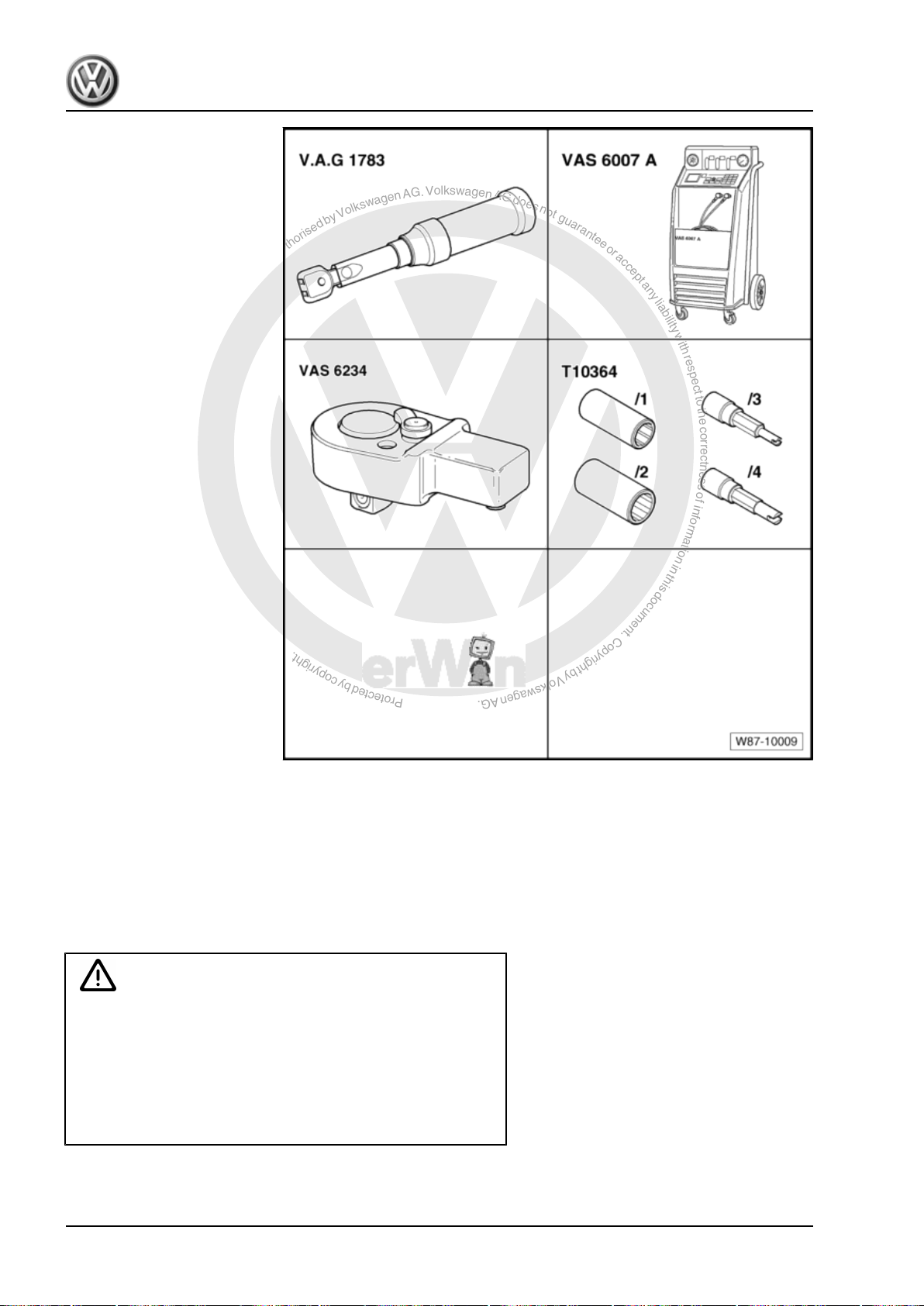
P
r
o
t
e
c
t
e
d
b
y
c
o
p
y
r
i
g
h
t
.
C
o
p
y
i
n
g
f
o
r
p
r
i
v
a
t
e
o
r
c
o
m
m
e
r
c
i
a
l
p
u
r
p
o
s
e
s
,
i
n
p
a
r
t
o
r
i
n
w
h
o
l
e
,
i
s
n
o
t
p
e
r
m
i
t
t
e
d
u
n
l
e
s
s
a
u
t
h
o
r
i
s
e
d
b
y
V
o
l
k
s
w
a
g
e
n
A
G
.
V
o
l
k
s
w
a
g
e
n
A
G
d
o
e
s
n
o
t
g
u
a
r
a
n
t
e
e
o
r
a
c
c
e
p
t
a
n
y
l
i
a
b
i
l
i
t
y
w
i
t
h
r
e
s
p
e
c
t
t
o
t
h
e
c
o
r
r
e
c
t
n
e
s
s
o
f
i
n
f
o
r
m
a
t
i
o
n
i
n
t
h
i
s
d
o
c
u
m
e
n
t
.
C
o
p
y
r
i
g
h
t
b
y
V
o
l
k
s
w
a
g
e
n
A
G
.
Golf Variant 2007 ➤ , Golf Variant 2010 ➤ , Jetta 2005 ➤ , Jetta 2011 ➤
Heating, air conditioning - Edition 04.2010
Special tools and workshop
equipment required
♦ Torque wrench -V.A.G
1783-
♦ E.g. air conditioner service
station -VAS 6007A- (or lat‐
er model)
♦ Ratchet insert tool 1/4" -
VAS 6234-
♦ Socket -T10364-
5.2 Renewing refrigerant circuit compo‐
nents
5.2.1 Renewing components of refrigerant cir‐
cuit (Golf Variant 2007►, Golf Variant
2010► und Jetta 2005►)
WARNING
Danger of freezing injuries.
If refrigerant circuit has not been evacuated, refrigerant will
escape.
Extract refrigerant before opening refrigerant circuit. If the re‐
frigerant circuit is not opened within 10 minutes after it has
been evacuated, pressure may develop in coolant circuit due
to re-evaporation. Extract refrigerant again.
92 Rep. gr.87 - Air conditioning system
Page 99
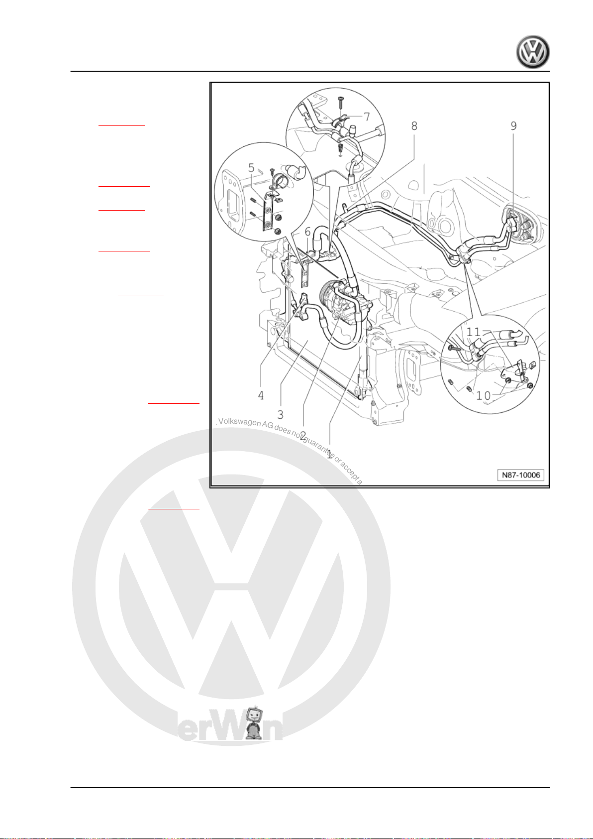
P
r
o
t
e
c
t
e
d
b
y
c
o
p
y
r
i
g
h
t
.
C
o
p
y
i
n
g
f
o
r
p
r
i
v
a
t
e
o
r
c
o
m
m
e
r
c
i
a
l
p
u
r
p
o
s
e
s
,
i
n
p
a
r
t
o
r
i
n
w
h
o
l
e
,
i
s
n
o
t
p
e
r
m
i
t
t
e
d
u
n
l
e
s
s
a
u
t
h
o
r
i
s
e
d
b
y
V
o
l
k
s
w
a
g
e
n
A
G
.
V
o
l
k
s
w
a
g
e
n
A
G
d
o
e
s
n
o
t
g
u
a
r
a
n
t
e
e
o
r
a
c
c
e
p
t
a
n
y
l
i
a
b
i
l
i
t
y
w
i
t
h
r
e
s
p
e
c
t
t
o
t
h
e
c
o
r
r
e
c
t
n
e
s
s
o
f
i
n
f
o
r
m
a
t
i
o
n
i
n
t
h
i
s
d
o
c
u
m
e
n
t
.
C
o
p
y
r
i
g
h
t
b
y
V
o
l
k
s
w
a
g
e
n
A
G
.
Golf Variant 2007 ➤ , Golf Variant 2010 ➤ , Jetta 2005 ➤ , Jetta 2011 ➤
1 - Receiver with dryer car‐
tridge
❑ Removing and installing
⇒ page 95
2 - Air conditioner compressor
❑ Observe remarks on in‐
stallation of air condi‐
tioner compressor
⇒ page 103 .
❑ Removing and installing
⇒ page 96
3 - Condenser
❑ Removing and installing
⇒ page 100
4 - High-pressure sender G65-
Removing ⇒ page 95
5 - Bracket
6 - Evacuating and charging
valve
❑ High-pressure side
❑ Releasing refrigerant in‐
to the environment is a
punishable offence.
❑ Capacities ⇒ page 105
7 - Retainer
8 - Evacuating and charging
valve
❑ Low-pressure side
❑ Releasing refrigerant in‐
to the environment is a
punishable offence.
❑ Capacities ⇒ page 105
9 - Expansion valve
❑ Function and removal ⇒ page 98 .
10 - Hexagon nut
❑ 20 Nm
11 - Bracket
Heating, air conditioning - Edition 04.2010
5. Repair work on refrigerant circuit which may be performed only in appropriate workshops by specially trained mechanics 93
Page 100
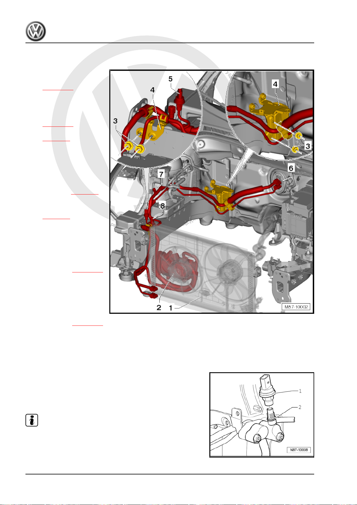
P
r
o
t
e
c
t
e
d
b
y
c
o
p
y
r
i
g
h
t
.
C
o
p
y
i
n
g
f
o
r
p
r
i
v
a
t
e
o
r
c
o
m
m
e
r
c
i
a
l
p
u
r
p
o
s
e
s
,
i
n
p
a
r
t
o
r
i
n
w
h
o
l
e
,
i
s
n
o
t
p
e
r
m
i
t
t
e
d
u
n
l
e
s
s
a
u
t
h
o
r
i
s
e
d
b
y
V
o
l
k
s
w
a
g
e
n
A
G
.
V
o
l
k
s
w
a
g
e
n
A
G
d
o
e
s
n
o
t
g
u
a
r
a
n
t
e
e
o
r
a
c
c
e
p
t
a
n
y
l
i
a
b
i
l
i
t
y
w
i
t
h
r
e
s
p
e
c
t
t
o
t
h
e
c
o
r
r
e
c
t
n
e
s
s
o
f
i
n
f
o
r
m
a
t
i
o
n
i
n
t
h
i
s
d
o
c
u
m
e
n
t
.
C
o
p
y
r
i
g
h
t
b
y
V
o
l
k
s
w
a
g
e
n
A
G
.
Golf Variant 2007 ➤ , Golf Variant 2010 ➤ , Jetta 2005 ➤ , Jetta 2011 ➤
Heating, air conditioning - Edition 04.2010
5.2.2 Renewing components of refrigerant circuit (Jetta 2010►)
1 - Condenser
❑ Removing and installing
⇒ page 100
2 - Air conditioner compressor
❑ Observe remarks on in‐
stallation of air condi‐
tioner compressor
⇒ page 103 .
❑ Removing and installing
⇒ page 96
3 - Hexagon nut
❑ 6 Nm
4 - Bracket
5 - High-pressure sender G65-
❑ Removing ⇒ page 95
6 - Expansion valve
❑ Function and removal
⇒ page 98 .
7 - Evacuating and charging
valve
❑ Low-pressure side
❑ Releasing refrigerant in‐
to the environment is a
punishable offence.
❑ Capacities ⇒ page 105
8 - Evacuating and charging
valve
❑ High-pressure side
❑ Releasing refrigerant in‐
to the environment is a
punishable offence.
❑ Capacities ⇒ page 105
5.3 Removing high-pressure sender -G65-
(Golf Variant 2007►, Golf Variant 2010►
und Jetta 2005►)
– Remove noise insulation from engine ⇒ Rep. gr. 50 .
– Disconnect connector from high-pressure sender -1-.
– Unscrew high-pressure sender -G65- -1- from refrigerant line
connection.
Note
♦
Renew O-ring -2-.
♦
Depending on engine version, the high-pressure sender -G65-
-1- may be installed in another location near the condenser.
94 Rep. gr.87 - Air conditioning system
 Loading...