


Volkswagen Amarok 2011 User Manual

P
r
o
t
e
c
t
e
d
b
y
c
o
p
y
r
i
g
h
t
.
C
o
p
y
i
n
g
f
o
r
p
r
i
v
a
t
e
o
r
c
o
m
m
e
r
c
i
a
l
p
u
r
p
o
s
e
s
,
i
n
p
a
r
t
o
r
i
n
w
h
o
l
e
,
i
s
n
o
t
p
e
r
m
i
t
t
e
d
u
n
l
e
s
s
a
u
t
h
o
r
i
s
e
d
b
y
V
o
l
k
s
w
a
g
e
n
A
G
.
V
o
l
k
s
w
a
g
e
n
A
G
d
o
e
s
n
o
t
g
u
a
r
a
n
t
e
e
o
r
a
c
c
e
p
t
a
n
y
l
i
a
b
i
l
i
t
y
w
i
t
h
r
e
s
p
e
c
t
t
o
t
h
e
c
o
r
r
e
c
t
n
e
s
s
o
f
i
n
f
o
r
m
a
t
i
o
n
i
n
t
h
i
s
d
o
c
u
m
e
n
t
.
C
o
p
y
r
i
g
h
t
b
y
V
o
l
k
s
w
a
g
e
n
A
G
.
Service
Workshop Manual
Amarok 2011 ➤ , Caddy 2004 ➤ ,
Caddy 2011 ➤ ,
Caddy Kasten/Kombi 1996 ➤ ,
Caddy Pickup 1997 ➤ ,
Caravelle 2010 ➤ , Crafter 2006 ➤ ,
LT 1997 ➤ , Multivan 2010 ➤ ,
Transporter 1991 ➤ ,
Transporter 1996 ➤ ,
Transporter 2004 ➤ ,
Transporter 2010 ➤ , Zugkopf 2010 ➤
Wheels and Tyres Guide
Edition 11.2012
Service Department. Technical Information
P
r
o
t
e
c
t
e
d
b
y
c
o
p
y
r
i
g
h
t
.
C
o
p
y
i
n
g
f
o
r
p
r
i
v
a
t
e
o
r
c
o
m
m
e
r
c
i
a
l
p
u
r
p
o
s
e
s
,
i
n
p
a
r
t
o
r
i
n
w
h
o
l
e
,
i
s
n
o
t
p
e
r
m
i
t
t
e
d
u
n
l
e
s
s
a
u
t
h
o
r
i
s
e
d
b
y
V
o
l
k
s
w
a
g
e
n
A
G
.
V
o
l
k
s
w
a
g
e
n
A
G
d
o
e
s
n
o
t
g
u
a
r
a
n
t
e
e
o
r
a
c
c
e
p
t
a
n
y
l
i
a
b
i
l
i
t
y
w
i
t
h
r
e
s
p
e
c
t
t
o
t
h
e
c
o
r
r
e
c
t
n
e
s
s
o
f
i
n
f
o
r
m
a
t
i
o
n
i
n
t
h
i
s
d
o
c
u
m
e
n
t
.
C
o
p
y
r
i
g
h
t
b
y
V
o
l
k
s
w
a
g
e
n
A
G
.
Service
List of Workshop Manual Repair GroupsList of Workshop Manual
Repair GroupsList of Workshop Manual Repair Groups
Re pa ir G ro up
44 - Wheels, tyres, vehicle geometry
Technical information should always be available to the foremen and mechanics, because their
careful and constant adherence to the instructions is essential to ensure vehicle road-worthiness and
safety. In addition, the normal basic safety precautions for working on motor vehicles must, as a
matter of course, be observed.
All rights reserved.
No reproduction without prior agreement from publisher.
Copyright © 2012 Volkswagen AG, Wolfsburg K0056560120

P
r
o
t
e
c
t
e
d
b
y
c
o
p
y
r
i
g
h
t
.
C
o
p
y
i
n
g
f
o
r
p
r
i
v
a
t
e
o
r
c
o
m
m
e
r
c
i
a
l
p
u
r
p
o
s
e
s
,
i
n
p
a
r
t
o
r
i
n
w
h
o
l
e
,
i
s
n
o
t
p
e
r
m
i
t
t
e
d
u
n
l
e
s
s
a
u
t
h
o
r
i
s
e
d
b
y
V
o
l
k
s
w
a
g
e
n
A
G
.
V
o
l
k
s
w
a
g
e
n
A
G
d
o
e
s
n
o
t
g
u
a
r
a
n
t
e
e
o
r
a
c
c
e
p
t
a
n
y
l
i
a
b
i
l
i
t
y
w
i
t
h
r
e
s
p
e
c
t
t
o
t
h
e
c
o
r
r
e
c
t
n
e
s
s
o
f
i
n
f
o
r
m
a
t
i
o
n
i
n
t
h
i
s
d
o
c
u
m
e
n
t
.
C
o
p
y
r
i
g
h
t
b
y
V
o
l
k
s
w
a
g
e
n
A
G
.
Amarok 2011 ➤ , Caddy 2004 ➤ , Caddy 2011 ➤ , Caddy Kasten/Kombi 1996 ➤ ...
Wheels and Tyres Guide - Edition 11.2012
Contents
44 - Wheels, tyres, vehicle geometry . . . . . . . . . . . . . . . . . . . . . . . . . . . . . . . . . . . . . . 1
1 General notes on wheels and tyres (commercial vehicles) . . . . . . . . . . . . . . . . . . . . . . . . 1
2 Legislative and technical conditions for converting wheel and tyre combinations . . . . . . . . 3
2.1 Legislative conditions for converting wheel and tyre combinations . . . . . . . . . . . . . . . . . . 3
2.2 Technical conditions for converting wheel and tyre combinations . . . . . . . . . . . . . . . . . . . . 3
2.3 Additional wheel housing extensions . . . . . . . . . . . . . . . . . . . . . . . . . . . . . . . . . . . . . . . . . . 4
2.4 “Series 80” tyres . . . . . . . . . . . . . . . . . . . . . . . . . . . . . . . . . . . . . . . . . . . . . . . . . . . . . . . . . . 4
3 Documents and codes/designations . . . . . . . . . . . . . . . . . . . . . . . . . . . . . . . . . . . . . . . . . . 5
3.1 New vehicle registration documents since 01.10.2005 . . . . . . . . . . . . . . . . . . . . . . . . . . . . 5
3.2 COC document (EEC Certificate of Conformity) . . . . . . . . . . . . . . . . . . . . . . . . . . . . . . . . 6
4 Official type designations . . . . . . . . . . . . . . . . . . . . . . . . . . . . . . . . . . . . . . . . . . . . . . . . . . 7
4.1 Official type approval, sales or trade designation . . . . . . . . . . . . . . . . . . . . . . . . . . . . . . . . 7
5 EU tyre label . . . . . . . . . . . . . . . . . . . . . . . . . . . . . . . . . . . . . . . . . . . . . . . . . . . . . . . . . . . . 10
5.1 EU tyre label, summary . . . . . . . . . . . . . . . . . . . . . . . . . . . . . . . . . . . . . . . . . . . . . . . . . . . . 10
5.2 EU tyre label, objectives . . . . . . . . . . . . . . . . . . . . . . . . . . . . . . . . . . . . . . . . . . . . . . . . . . . . 11
5.3 EU tyre label, categories . . . . . . . . . . . . . . . . . . . . . . . . . . . . . . . . . . . . . . . . . . . . . . . . . . 12
6 Facts about wheels and tyres (commercial vehicles) . . . . . . . . . . . . . . . . . . . . . . . . . . . . . . 15
6.1 Useful information regarding tyres . . . . . . . . . . . . . . . . . . . . . . . . . . . . . . . . . . . . . . . . . . . . 15
6.2 Tyre wear/ mileage . . . . . . . . . . . . . . . . . . . . . . . . . . . . . . . . . . . . . . . . . . . . . . . . . . . . . . . . 23
6.3 Tyre noise . . . . . . . . . . . . . . . . . . . . . . . . . . . . . . . . . . . . . . . . . . . . . . . . . . . . . . . . . . . . . . 32
6.4 Rough running caused by wheels/tyres . . . . . . . . . . . . . . . . . . . . . . . . . . . . . . . . . . . . . . . . 35
6.5 Vehicle pulls to one side . . . . . . . . . . . . . . . . . . . . . . . . . . . . . . . . . . . . . . . . . . . . . . . . . . . . 43
6.6 Tyre damage . . . . . . . . . . . . . . . . . . . . . . . . . . . . . . . . . . . . . . . . . . . . . . . . . . . . . . . . . . . . 48
6.7 Useful information about rims . . . . . . . . . . . . . . . . . . . . . . . . . . . . . . . . . . . . . . . . . . . . . . . . 55
6.8 Fitting and removing wheels . . . . . . . . . . . . . . . . . . . . . . . . . . . . . . . . . . . . . . . . . . . . . . . . 59
6.9 Breakdown set for VW Vehicles . . . . . . . . . . . . . . . . . . . . . . . . . . . . . . . . . . . . . . . . . . . . . . 63
7 Wheel and tyre combinations, Amarok . . . . . . . . . . . . . . . . . . . . . . . . . . . . . . . . . . . . . . . . 64
7.1 Vehicles without wheel house extension . . . . . . . . . . . . . . . . . . . . . . . . . . . . . . . . . . . . . . 64
7.2 Wheel allocation for vehicles without wheel house extension . . . . . . . . . . . . . . . . . . . . . . 65
7.3 Vehicles with wheel house extension . . . . . . . . . . . . . . . . . . . . . . . . . . . . . . . . . . . . . . . . . . 66
7.4 Wheel allocation for vehicles with wheel house extension . . . . . . . . . . . . . . . . . . . . . . . . . . 69
8 Wheel and tyre combinations, Caddy model year 1996 to model year 2002 . . . . . . . . . . . . 72
8.1 Appendix for parts certificate, Caddy Kombi, type 9KV and Caddy panel van, type 9KVF,
model year 1996 to model year 2002 . . . . . . . . . . . . . . . . . . . . . . . . . . . . . . . . . . . . . . . . . . 72
8.2 Wheel allocation for Caddy Kombi type 9 KV and Caddy panel van type 9KVF, model year
1996 to model year 2002 . . . . . . . . . . . . . . . . . . . . . . . . . . . . . . . . . . . . . . . . . . . . . . . . . . 73
9 Wheel and tyre combinations, Caddy pickup, model year 1997 to model year 2002 . . . . . . 76
9.1 Appendix for parts certificate, Caddy pickup, type 9U, model year 1997 to model year
2002 . . . . . . . . . . . . . . . . . . . . . . . . . . . . . . . . . . . . . . . . . . . . . . . . . . . . . . . . . . . . . . . . . . 76
9.2 Wheel allocation Caddy pickup, type 9U, model year 1997 to model year 2002 . . . . . . . . 77
10 Wheel and tyre combinations, Caddy, from model year 2004 to 2011 (model code 2K) . . 78
10.1 Appendix for certificate statement, Caddy panel van, sales type 2KA, model year 2004 to
model year 2008 . . . . . . . . . . . . . . . . . . . . . . . . . . . . . . . . . . . . . . . . . . . . . . . . . . . . . . . . . . 78
10.2 Appendix for certificate statement, Caddy panel van, sales type 2KA, from model year 2009
to model year 2011 . . . . . . . . . . . . . . . . . . . . . . . . . . . . . . . . . . . . . . . . . . . . . . . . . . . . . . . . 80
10.3 Wheel allocation for Caddy panel van, sales type 2KA, from model year 2004 to model year
2011 . . . . . . . . . . . . . . . . . . . . . . . . . . . . . . . . . . . . . . . . . . . . . . . . . . . . . . . . . . . . . . . . . . 81
10.4 Appendix for parts certificate, Caddy Maxi panel van, sales type 2KH, from model year 2008
to model year 2011 . . . . . . . . . . . . . . . . . . . . . . . . . . . . . . . . . . . . . . . . . . . . . . . . . . . . . . . . 83
10.5 Wheel allocation for Caddy Maxi panel van, sales type 2KH, from model year 2008 to model
year 2011 . . . . . . . . . . . . . . . . . . . . . . . . . . . . . . . . . . . . . . . . . . . . . . . . . . . . . . . . . . . . . . 85
10.6 Appendix for parts certificate, Caddy Kombi, sales type 2KB, model year 2004 to model year
2008 . . . . . . . . . . . . . . . . . . . . . . . . . . . . . . . . . . . . . . . . . . . . . . . . . . . . . . . . . . . . . . . . . . 86
Contents i
P
r
o
t
e
c
t
e
d
b
y
c
o
p
y
r
i
g
h
t
.
C
o
p
y
i
n
g
f
o
r
p
r
i
v
a
t
e
o
r
c
o
m
m
e
r
c
i
a
l
p
u
r
p
o
s
e
s
,
i
n
p
a
r
t
o
r
i
n
w
h
o
l
e
,
i
s
n
o
t
p
e
r
m
i
t
t
e
d
u
n
l
e
s
s
a
u
t
h
o
r
i
s
e
d
b
y
V
o
l
k
s
w
a
g
e
n
A
G
.
V
o
l
k
s
w
a
g
e
n
A
G
d
o
e
s
n
o
t
g
u
a
r
a
n
t
e
e
o
r
a
c
c
e
p
t
a
n
y
l
i
a
b
i
l
i
t
y
w
i
t
h
r
e
s
p
e
c
t
t
o
t
h
e
c
o
r
r
e
c
t
n
e
s
s
o
f
i
n
f
o
r
m
a
t
i
o
n
i
n
t
h
i
s
d
o
c
u
m
e
n
t
.
C
o
p
y
r
i
g
h
t
b
y
V
o
l
k
s
w
a
g
e
n
A
G
.
Amarok 2011 ➤ , Caddy 2004 ➤ , Caddy 2011 ➤ , Caddy Kasten/Kombi 1996 ➤ ...
Wheels and Tyres Guide - Edition 11.2012
10.7 Appendix for parts certificate, Caddy Kombi, sales type 2KB, from model year 2009 to model
year 2011 . . . . . . . . . . . . . . . . . . . . . . . . . . . . . . . . . . . . . . . . . . . . . . . . . . . . . . . . . . . . . . 87
10.8 Wheel allocation for Caddy Kombi, sales type 2KB, from model year 2004 to model year
2011 . . . . . . . . . . . . . . . . . . . . . . . . . . . . . . . . . . . . . . . . . . . . . . . . . . . . . . . . . . . . . . . . . . 89
10.9 Appendix for parts certificate, Caddy Maxi Kombi, sales type 2KJ, from model year 2008 to
model year 2011 . . . . . . . . . . . . . . . . . . . . . . . . . . . . . . . . . . . . . . . . . . . . . . . . . . . . . . . . . . 90
10.10 Wheel allocation for Caddy Maxi Kombi, sales type 2KJ, from model year 2008 to model year
2011 . . . . . . . . . . . . . . . . . . . . . . . . . . . . . . . . . . . . . . . . . . . . . . . . . . . . . . . . . . . . . . . . . . 92
11 Wheel and tyre combinations, Caddy, from model year 2011 . . . . . . . . . . . . . . . . . . . . . . 95
11.1 Appendix for certificate statement for Caddy panel van, sales type 2CA from model year
2011 . . . . . . . . . . . . . . . . . . . . . . . . . . . . . . . . . . . . . . . . . . . . . . . . . . . . . . . . . . . . . . . . . . 95
11.2 Wheel allocation Caddy panel van, sales type 2CA from model year 2011 . . . . . . . . . . . . 96
11.3 Appendix for certificate statement for Caddy Kombi, sales type 2CB from model year 2011
. . . . . . . . . . . . . . . . . . . . . . . . . . . . . . . . . . . . . . . . . . . . . . . . . . . . . . . . . . . . . . . . . . . . . . . . 98
11.4 Wheel allocation for Caddy Kombi, sales type 2CB from model year 2011 . . . . . . . . . . . . 100
11.5 Appendix for certificate statement for Caddy Maxi panel van, sales type 2CH from model year
2011 . . . . . . . . . . . . . . . . . . . . . . . . . . . . . . . . . . . . . . . . . . . . . . . . . . . . . . . . . . . . . . . . . . 102
11.6 Wheel allocation for Caddy Maxi panel van, sales type 2CH from model year 2011 . . . . . . 104
11.7 Appendix for certificate statement for Caddy Maxi Kombi, sales type 2CJ from model year
2011 . . . . . . . . . . . . . . . . . . . . . . . . . . . . . . . . . . . . . . . . . . . . . . . . . . . . . . . . . . . . . . . . . . 106
11.8 Wheel allocation for Caddy Maxi Kombi, sales type 2CJ from model year 2011 . . . . . . . . 109
12 Wheel and tyre combinations, Transporter model year 1991 to model year 1995 . . . . . . . . 112
12.1 Appendix for parts certificate, Transporter, Transporter Syncro, type 70X0 A to D and 70X1
A to D, model year 1991 to model year 1995 . . . . . . . . . . . . . . . . . . . . . . . . . . . . . . . . . . . . 112
12.2 Wheel allocation Transporter, Transporter Syncro, type 70X0 A to D and 70X1 A to D model
year 1991 to model year 1995 . . . . . . . . . . . . . . . . . . . . . . . . . . . . . . . . . . . . . . . . . . . . . . 114
13 Wheel and tyre combinations, Transporter from January 1996 to model year 2003 . . . . . . 117
13.1 Appendix for parts certificate, Transporter, Transporter Syncro, type 70X02 A to D and 70X12
A to D, from January 1996 to model year 2003 . . . . . . . . . . . . . . . . . . . . . . . . . . . . . . . . . . 117
13.2 Transporter, Transporter Syncro from January 1996 to model year 2003 (passenger
vehicles) . . . . . . . . . . . . . . . . . . . . . . . . . . . . . . . . . . . . . . . . . . . . . . . . . . . . . . . . . . . . . . . . 118
13.3 Wheel allocation Transporter, Transporter Syncro from January 1996 to model year 2003
(passenger vehicles) . . . . . . . . . . . . . . . . . . . . . . . . . . . . . . . . . . . . . . . . . . . . . . . . . . . . . . 119
13.4 Transporter, Transporter Syncro, 111 kW TDI model year 2000 . . . . . . . . . . . . . . . . . . . . 121
13.5 Wheel allocation Transporter, Transporter Syncro, 111 kW TDI model year 2000 . . . . . . 122
13.6 Transporter, Transporter Syncro 111 kW TDI and V6 150 kW from model year 2001 to model
year 2003 as well as 65 kW, 75 kW and 85 kW from model year 2002 to model year 2003
. . . . . . . . . . . . . . . . . . . . . . . . . . . . . . . . . . . . . . . . . . . . . . . . . . . . . . . . . . . . . . . . . . . . . . . . 123
13.7 Wheel allocation Transporter, Transporter Syncro 111 kW TDI and V6 150 kW from model
year 2001 to model year 2003 as well as 65 kW, 75 kW and 85 kW from model year 2002 to
model year 2003 . . . . . . . . . . . . . . . . . . . . . . . . . . . . . . . . . . . . . . . . . . . . . . . . . . . . . . . . . . 124
14 Wheel and tyre combinations, Transporter from model year 2004 to model year 2009 . . . . 126
14.1 Appendix for parts certificate Transporter, sales type 7HM Multivan model year 2004 to model
year 2007 . . . . . . . . . . . . . . . . . . . . . . . . . . . . . . . . . . . . . . . . . . . . . . . . . . . . . . . . . . . . . . 126
14.2 Wheel allocation for Transporter, sales type 7HM Multivan model year 2004 to model year
2007 . . . . . . . . . . . . . . . . . . . . . . . . . . . . . . . . . . . . . . . . . . . . . . . . . . . . . . . . . . . . . . . . . . 128
14.3 Appendix for parts certificate Transporter, sales type 7HM Multivan model year 2008 to model
year 2009 . . . . . . . . . . . . . . . . . . . . . . . . . . . . . . . . . . . . . . . . . . . . . . . . . . . . . . . . . . . . . . 131
14.4 Wheel allocation for Transporter, sales type 7HM Multivan model year 2008 to model year
2009 . . . . . . . . . . . . . . . . . . . . . . . . . . . . . . . . . . . . . . . . . . . . . . . . . . . . . . . . . . . . . . . . . . 133
14.5 Appendix for parts certificate Transporter, sales type 7HC California model year 2004 to
model year 2007 . . . . . . . . . . . . . . . . . . . . . . . . . . . . . . . . . . . . . . . . . . . . . . . . . . . . . . . . . . 136
14.6 Wheel allocation for Transporter, sales type 7HC California model year 2004 to model year
2007 . . . . . . . . . . . . . . . . . . . . . . . . . . . . . . . . . . . . . . . . . . . . . . . . . . . . . . . . . . . . . . . . . . 138
14.7 Appendix for parts certificate Transporter, sales type 7HC California model year 2008 to
model year 2009 . . . . . . . . . . . . . . . . . . . . . . . . . . . . . . . . . . . . . . . . . . . . . . . . . . . . . . . . . . 140
14.8 Wheel allocation for Transporter, sales type 7HC California model year 2008 to model year
2009 . . . . . . . . . . . . . . . . . . . . . . . . . . . . . . . . . . . . . . . . . . . . . . . . . . . . . . . . . . . . . . . . . . 143
14.9 Appendix for parts certificate Transporter, sales type 7HF, Multivan Beach model year 2004
to model year 2007 . . . . . . . . . . . . . . . . . . . . . . . . . . . . . . . . . . . . . . . . . . . . . . . . . . . . . . . . 146
ii Contents

P
r
o
t
e
c
t
e
d
b
y
c
o
p
y
r
i
g
h
t
.
C
o
p
y
i
n
g
f
o
r
p
r
i
v
a
t
e
o
r
c
o
m
m
e
r
c
i
a
l
p
u
r
p
o
s
e
s
,
i
n
p
a
r
t
o
r
i
n
w
h
o
l
e
,
i
s
n
o
t
p
e
r
m
i
t
t
e
d
u
n
l
e
s
s
a
u
t
h
o
r
i
s
e
d
b
y
V
o
l
k
s
w
a
g
e
n
A
G
.
V
o
l
k
s
w
a
g
e
n
A
G
d
o
e
s
n
o
t
g
u
a
r
a
n
t
e
e
o
r
a
c
c
e
p
t
a
n
y
l
i
a
b
i
l
i
t
y
w
i
t
h
r
e
s
p
e
c
t
t
o
t
h
e
c
o
r
r
e
c
t
n
e
s
s
o
f
i
n
f
o
r
m
a
t
i
o
n
i
n
t
h
i
s
d
o
c
u
m
e
n
t
.
C
o
p
y
r
i
g
h
t
b
y
V
o
l
k
s
w
a
g
e
n
A
G
.
Amarok 2011 ➤ , Caddy 2004 ➤ , Caddy 2011 ➤ , Caddy Kasten/Kombi 1996 ➤ ...
Wheels and Tyres Guide - Edition 11.2012
14.10 Wheel allocation for Transporter, sales type 7HF; Multivan Beach model year 2004 to model
year 2007 . . . . . . . . . . . . . . . . . . . . . . . . . . . . . . . . . . . . . . . . . . . . . . . . . . . . . . . . . . . . . . 148
14.11 Appendix for parts certificate, Transporter, sales type 7HF; Multivan Beach, Multivan
Startline, California Beach model year 2008 to model year 2009 . . . . . . . . . . . . . . . . . . . . 150
14.12 Wheel allocation for Transporter, sales type 7HF; Multivan Beach, Multivan Startline,
California Beach model year 2008 to model year 2009 . . . . . . . . . . . . . . . . . . . . . . . . . . . . 152
14.13 Appendix for parts certificate, Transporter Kombi; Transporter Shuttle; Caravelle, sales type
7HB and 7HJ model year 2004 to model year 2007 . . . . . . . . . . . . . . . . . . . . . . . . . . . . . . 156
14.14 Wheel allocation for Transporter Kombi; Transporter Shuttle; Caravelle, sales type 7HB and
7HJ model year 2004 to model year 2007 . . . . . . . . . . . . . . . . . . . . . . . . . . . . . . . . . . . . . . 157
14.15 Appendix for parts certificate, Transporter Kombi; Transporter Shuttle; Caravelle, sales type
14.16 Wheel allocation for Transporter Kombi; Transporter Shuttle; Caravelle, sales type 7HB and
14.17 Appendix for parts certificate, Transporter, sales type 7JD; 7JE; 7JL; 7JZ with a maximum
14.18 Wheel allocation for Transporter, sales type 7JD; 7JE; 7JL; 7JZ with a maximum permitted
14.19 Appendix for parts certificate, Transporter, sales type 7JD; 7JE; 7JL; 7JZ with a maximum
14.20 Wheel allocation for Transporter, sales type 7JD; 7JE; 7JL; 7JZ with a maximum permitted
14.21 Appendix for parts certificate, Transporter panel van, sales type 7HA and 7HH with a
14.22 Wheel allocation for Transporter panel van, sales type 7HA and 7HH with a maximum
14.23 Appendix for parts certificate, Transporter panel van, sales type 7HA and 7HH with a
14.24 Wheel allocation for Transporter panel van, sales type 7HA and 7HH with a maximum
14.25 Appendix for parts certificate, Transporter panel van, sales type 7HA and 7HH with a
7HB and 7HJ model year 2008 to model year 2009 . . . . . . . . . . . . . . . . . . . . . . . . . . . . . . 159
7HJ model year 2008 to model year 2009 . . . . . . . . . . . . . . . . . . . . . . . . . . . . . . . . . . . . . . 161
permitted weight to 3000 kg, model year 2004 to model year 2007 . . . . . . . . . . . . . . . . . . 164
weight to 3000 kg, model year 2004 to model year 2007 . . . . . . . . . . . . . . . . . . . . . . . . . . 166
permitted weight to 3000 kg, model year 2008 to model year 2009 . . . . . . . . . . . . . . . . . . 168
weight to 3000 kg, model year 2008 to model year 2009 . . . . . . . . . . . . . . . . . . . . . . . . . . 170
maximum permitted weight to 3000 kg, model year 2004 to model year 2007 . . . . . . . . . . 173
permitted weight to 3000 kg, model year 2004 to model year 2007 . . . . . . . . . . . . . . . . . . 174
maximum permitted weight to 3000 kg, model year 2008 to model year 2009 . . . . . . . . . . 177
permitted weight to 3000 kg, model year 2008 to model year 2009 . . . . . . . . . . . . . . . . . . 178
maximum permitted weight of 3200 kg, model year 2004 to model year 2007 . . . . . . . . . . 182
14.26 Wheel allocation for Transporter panel van, sales type 7HA and 7HH with a maximum
permitted weight of 3200 kg, model year 2004 to model year 2007 . . . . . . . . . . . . . . . . . . 183
14.27 Appendix for parts certificate, Transporter panel van, sales type 7HA and 7HH with a
maximum permitted weight of 3200 kg, model year 2008 to model year 2009 . . . . . . . . . . 184
14.28 Wheel allocation for Transporter panel van, sales type 7HA and 7HH with a maximum
permitted weight of 3200 kg, model year 2008 to model year 2009 . . . . . . . . . . . . . . . . . . 186
15 Wheel and tyre combinations, Transporter, from model year 2010 . . . . . . . . . . . . . . . . . . 188
15.1 Appendix for certificate statement, Transporter with a maximum permitted weight to 3080
kg . . . . . . . . . . . . . . . . . . . . . . . . . . . . . . . . . . . . . . . . . . . . . . . . . . . . . . . . . . . . . . . . . . . . 188
15.2 Wheel allocation for Transporter with a maximum permitted weight to 3080 kg . . . . . . . . 191
15.3 Appendix for certificate statement, Transporter with a maximum permitted weight to 3080
kg . . . . . . . . . . . . . . . . . . . . . . . . . . . . . . . . . . . . . . . . . . . . . . . . . . . . . . . . . . . . . . . . . . . . 196
15.4 Wheel allocation for Transporter with a maximum permitted weight to 3080 kg . . . . . . . . 199
15.5 Appendix for certificate statement, Transporter with a maximum permitted weight to 3080
kg . . . . . . . . . . . . . . . . . . . . . . . . . . . . . . . . . . . . . . . . . . . . . . . . . . . . . . . . . . . . . . . . . . . . 204
15.6 Wheel allocation for Transporter with a maximum permitted weight to 3080 kg . . . . . . . . 208
15.7 Appendix for certificate statement, Transporter with a maximum permitted weight above 3080
kg . . . . . . . . . . . . . . . . . . . . . . . . . . . . . . . . . . . . . . . . . . . . . . . . . . . . . . . . . . . . . . . . . . . . 214
15.8 Wheel allocation for Transporter with a maximum permitted weight above 3080 kg . . . . . . 216
16 Wheel and tyre combinations, LT, model year 1997 to model year 2006 . . . . . . . . . . . . . . 219
16.1 Appendix for parts certificate, LT, type 2DM model year 1997 to model year 2006 . . . . . . 219
16.2 Wheel allocation for LT type 2DM, model year 1997 to model year 2006 . . . . . . . . . . . . . . 221
17 Wheel and tyre combinations, Crafter, from model year 2006 . . . . . . . . . . . . . . . . . . . . . . 223
17.1 Appendix for certificate statements, Crafter 30 Kombi, sales type 2EB, 2EE with a maximum
permitted weight to 3190 kg, from model year 2006 . . . . . . . . . . . . . . . . . . . . . . . . . . . . . . 223
17.2 Wheel allocation, Crafter 30 Kombi, sales type 2EB, 2EE with a maximum permitted weight
to 3190 kg from model year 2006 . . . . . . . . . . . . . . . . . . . . . . . . . . . . . . . . . . . . . . . . . . . . 224
17.3 Appendix for certificate statements, Crafter 35 Kombi, sales type 2EB, 2EE, 2EK with a
maximum permitted weight to 3500 kg, from model year 2006 . . . . . . . . . . . . . . . . . . . . . . 226
Contents iii
P
r
o
t
e
c
t
e
d
b
y
c
o
p
y
r
i
g
h
t
.
C
o
p
y
i
n
g
f
o
r
p
r
i
v
a
t
e
o
r
c
o
m
m
e
r
c
i
a
l
p
u
r
p
o
s
e
s
,
i
n
p
a
r
t
o
r
i
n
w
h
o
l
e
,
i
s
n
o
t
p
e
r
m
i
t
t
e
d
u
n
l
e
s
s
a
u
t
h
o
r
i
s
e
d
b
y
V
o
l
k
s
w
a
g
e
n
A
G
.
V
o
l
k
s
w
a
g
e
n
A
G
d
o
e
s
n
o
t
g
u
a
r
a
n
t
e
e
o
r
a
c
c
e
p
t
a
n
y
l
i
a
b
i
l
i
t
y
w
i
t
h
r
e
s
p
e
c
t
t
o
t
h
e
c
o
r
r
e
c
t
n
e
s
s
o
f
i
n
f
o
r
m
a
t
i
o
n
i
n
t
h
i
s
d
o
c
u
m
e
n
t
.
C
o
p
y
r
i
g
h
t
b
y
V
o
l
k
s
w
a
g
e
n
A
G
.
Amarok 2011 ➤ , Caddy 2004 ➤ , Caddy 2011 ➤ , Caddy Kasten/Kombi 1996 ➤ ...
Wheels and Tyres Guide - Edition 11.2012
17.4 Wheel allocation for Crafter 35 Kombi, sales type 2EB, 2EE, 2EK with a maximum permitted
weight to 3500 kg, from model year 2006 . . . . . . . . . . . . . . . . . . . . . . . . . . . . . . . . . . . . . . 227
17.5 Appendix for certificate statements Crafter 30 panel van, sales type 2EA, 2ED with a
maximum permitted weight to 3025 kg, from model year 2006 . . . . . . . . . . . . . . . . . . . . . . 229
17.6 Wheel allocation for Crafter 30 panel van, sales type 2EA, 2ED with a maximum permitted
weight to 3025 kg from model year 2006 . . . . . . . . . . . . . . . . . . . . . . . . . . . . . . . . . . . . . . 229
17.7 Appendix for certificate statement Crafter 35 panel van, sales type 2EA, 2ED, 2EH, 2EX with
a maximum permitted weight to 3880 kg, from model year 2006 . . . . . . . . . . . . . . . . . . . . 231
17.8 Wheel allocation for Crafter 35 panel van, sales type 2EA, 2ED, 2EH, 2EX with a maximum
permitted weight to 3880 kg, from model year 2006 . . . . . . . . . . . . . . . . . . . . . . . . . . . . . . 232
17.9 Appendix for certificate statement Crafter 50 panel van, sales type 2ED, 2EH, 2EX with a
maximum permitted weight to 5000 kg, from model year 2006 . . . . . . . . . . . . . . . . . . . . . . 234
17.10 Wheel allocation for Crafter 50 panel van, sales type 2ED, 2EH, 2EX with a maximum
permitted weight to 5000 kg, from model year 2006 . . . . . . . . . . . . . . . . . . . . . . . . . . . . . . 236
17.11 Appendix for certificate statement for Crafter 30 chassis, dropside, sales type 2FF with a
maximum permitted weight to 3025 kg, from model year 2006 . . . . . . . . . . . . . . . . . . . . . . 238
17.12 Wheel allocation for Crafter 30 chassis, dropside, sales type 2FF with a maximum permitted
weight to 3025 kg, from model year 2006 . . . . . . . . . . . . . . . . . . . . . . . . . . . . . . . . . . . . . . 239
17.13 Appendix for certificate statements for Crafter 35 chassis, dropside, sales type 2FC, 2FF,
2FG, 2FL, 2FM, 2FZ with a maximum permitted weight to 3880 kg, from model year 2006
. . . . . . . . . . . . . . . . . . . . . . . . . . . . . . . . . . . . . . . . . . . . . . . . . . . . . . . . . . . . . . . . . . . . . . . . 241
17.14 Wheel allocation for Crafter 35 chassis, dropside, sales type 2FC, 2FF, 2FG, 2FL, 2FM, 2FZ
with a maximum permitted weight to 3880 kg, from model year 2006 . . . . . . . . . . . . . . . . 242
17.15 Appendix for certificate statements for Crafter 50 chassis, dropside, sales type 2FF, 2FG,
2FL, 2FM with a maximum permitted weight to 5000 kg, from model year 2006 . . . . . . . . 244
17.16 Wheel allocation for Crafter 50 chassis, dropside, sales type 2FF, 2FG, 2FL, 2FM with a
maximum permitted weight to 5000 kg, from model year 2006 . . . . . . . . . . . . . . . . . . . . . . 246
18 Recommended summer tyres . . . . . . . . . . . . . . . . . . . . . . . . . . . . . . . . . . . . . . . . . . . . . . 249
18.1 Summer tyres, Amarok . . . . . . . . . . . . . . . . . . . . . . . . . . . . . . . . . . . . . . . . . . . . . . . . . . . . 249
18.2 Summer tyres for Caddy, model year 1996 to model year 2002 . . . . . . . . . . . . . . . . . . . . 249
18.3 Summer tyres for Caddy Pick Up, model year 1997 to model year 2002 . . . . . . . . . . . . . . 250
18.4 Summer tyres for Caddy panel van, sales type 2KA from model year 2004 . . . . . . . . . . . . 250
18.5 Summer tyres Caddy Maxi panel van, sales type 2KH from model year 2008 . . . . . . . . . . 250
18.6 Summer tyres for Caddy Kombi, sales type 2KB from model year 2004 . . . . . . . . . . . . . . 251
18.7 Summer tyres Caddy Maxi Kombi, sales type 2KJ from model year 2008 . . . . . . . . . . . . 251
18.8 Summer tyres Caddy panel van, sales type 2CA from model year 2011 . . . . . . . . . . . . . . 252
18.9 Summer tyres Caddy Maxi panel van, sales type 2CH from model year 2011 . . . . . . . . . . 252
18.10 Summer tyres for Caddy Kombi, sales type 2CB, from model year 2011 . . . . . . . . . . . . . . 253
18.11 Summer tyres for Caddy Maxi Kombi, sales type 2CH , from model year 2011 . . . . . . . . 253
18.12 Summer tyres for Transporter, model year 1991 to model year 1995 . . . . . . . . . . . . . . . . 254
18.13 Summer tyres for Transporter from January 1996 to model year 2003 . . . . . . . . . . . . . . . . 254
18.14 Summer tyres for Transporter, sales type 7HM Multivan from model year 2004 . . . . . . . . 255
18.15 Summer tyres for Transporter, sales type 7HC California from model year 2004 . . . . . . . . 255
18.16 Summer tyres for Transporter, sales type 7HF; Multivan Beach, Multivan Startline from model
year 2004 . . . . . . . . . . . . . . . . . . . . . . . . . . . . . . . . . . . . . . . . . . . . . . . . . . . . . . . . . . . . . . 256
18.17 Summer tyres for Transporter Kombi, Transporter Shuttle, Caravelle, sales type 7HB and
7HJ, from model year 2004 . . . . . . . . . . . . . . . . . . . . . . . . . . . . . . . . . . . . . . . . . . . . . . . . 256
18.18 Summer tyres for Transporter, sales type 7JD; 7JE; 7JL; 7JZ with a maximum permitted
weight to 3000 kg, from model year 2004 . . . . . . . . . . . . . . . . . . . . . . . . . . . . . . . . . . . . . . 257
18.19 Summer tyres for Transporter panel van, sales type 7HA and 7HH with a maximum permitted
weight to 3000 kg, from model year 2004 . . . . . . . . . . . . . . . . . . . . . . . . . . . . . . . . . . . . . . 257
18.20 Summer tyres for Transporter panel van, sales type 7HA and 7HH with a maximum permitted
weight 3200 kg, from model year 2004 . . . . . . . . . . . . . . . . . . . . . . . . . . . . . . . . . . . . . . . . 258
18.21 Summer tyres for Transporter with a maximum permitted weight 3080 kg, from model year
2010 . . . . . . . . . . . . . . . . . . . . . . . . . . . . . . . . . . . . . . . . . . . . . . . . . . . . . . . . . . . . . . . . . . 258
18.22 Summer tyres for Transporter with a maximum permitted weight above 3080 kg, from model
year 2010 . . . . . . . . . . . . . . . . . . . . . . . . . . . . . . . . . . . . . . . . . . . . . . . . . . . . . . . . . . . . . . 259
18.23 Summer tyres for LT, model year 1997 to model year 2005 . . . . . . . . . . . . . . . . . . . . . . . . 259
18.24 Summer tyres for Crafter 30 Kombi, sales type 2EB, 2EE with a maximum permitted weight
to 3025 kg, from model year 2006 . . . . . . . . . . . . . . . . . . . . . . . . . . . . . . . . . . . . . . . . . . . . 259
iv Contents

P
r
o
t
e
c
t
e
d
b
y
c
o
p
y
r
i
g
h
t
.
C
o
p
y
i
n
g
f
o
r
p
r
i
v
a
t
e
o
r
c
o
m
m
e
r
c
i
a
l
p
u
r
p
o
s
e
s
,
i
n
p
a
r
t
o
r
i
n
w
h
o
l
e
,
i
s
n
o
t
p
e
r
m
i
t
t
e
d
u
n
l
e
s
s
a
u
t
h
o
r
i
s
e
d
b
y
V
o
l
k
s
w
a
g
e
n
A
G
.
V
o
l
k
s
w
a
g
e
n
A
G
d
o
e
s
n
o
t
g
u
a
r
a
n
t
e
e
o
r
a
c
c
e
p
t
a
n
y
l
i
a
b
i
l
i
t
y
w
i
t
h
r
e
s
p
e
c
t
t
o
t
h
e
c
o
r
r
e
c
t
n
e
s
s
o
f
i
n
f
o
r
m
a
t
i
o
n
i
n
t
h
i
s
d
o
c
u
m
e
n
t
.
C
o
p
y
r
i
g
h
t
b
y
V
o
l
k
s
w
a
g
e
n
A
G
.
Amarok 2011 ➤ , Caddy 2004 ➤ , Caddy 2011 ➤ , Caddy Kasten/Kombi 1996 ➤ ...
Wheels and Tyres Guide - Edition 11.2012
18.25 Summer tyres for Crafter 35 Kombi, sales type 2EB, 2EE, 2EK with a maximum permitted
weight to 3500 kg, from model year 2006 . . . . . . . . . . . . . . . . . . . . . . . . . . . . . . . . . . . . . . 260
18.26 Summer tyres for Crafter 30 panel van, sales type 2EA, 2ED with a maximum permitted
weight to 3025 kg, from model year 2006 . . . . . . . . . . . . . . . . . . . . . . . . . . . . . . . . . . . . . . 260
18.27 Summer tyres for Crafter 35 panel van, sales type 2EA, 2ED, 2EH, 2EX with a maximum
permitted weight to 3880 kg from model year 2006 . . . . . . . . . . . . . . . . . . . . . . . . . . . . . . 260
18.28 Summer tyres for Crafter 50 panel van, sales type 2ED, 2EH, 2EX with a maximum permitted
weight to 5000 kg, from model year 2006 . . . . . . . . . . . . . . . . . . . . . . . . . . . . . . . . . . . . . . 261
18.29 Summer tyres for Crafter 30 chassis, dropside, sales type 2FF with a maximum permitted
weight to 3025 kg, from model year 2006 . . . . . . . . . . . . . . . . . . . . . . . . . . . . . . . . . . . . . . 261
18.30 Summer tyres for Crafter 35 chassis, dropside, sales type 2FC, 2FF, 2FG, 2FL, 2FM, 2FZ
with a maximum permitted weight to 3880 kg, from model year 2006 . . . . . . . . . . . . . . . . 261
18.31 Summer tyres for Crafter 50 chassis, dropside, sales type 2FF, 2FG, 2FL, 2FM with a
19 Recommended all-season tyres . . . . . . . . . . . . . . . . . . . . . . . . . . . . . . . . . . . . . . . . . . . . . . 263
19.1 All-season tyres for Caddy, model year 1996 to model year 2002 . . . . . . . . . . . . . . . . . . . . 263
19.2 All-season tyres for Caddy panel van, sales type 2KA, from model year 2004 . . . . . . . . . . 263
19.3 All-season tyres Caddy Maxi panel van, sales type 2KH, from model year 2008 . . . . . . . . 263
19.4 All-season tyres for Caddy Kombi, sales type 2KB, from model year 2004 . . . . . . . . . . . . 264
19.5 All-season tyres Caddy Maxi Kombi, sales type 2KJ, from model year 2008 . . . . . . . . . . 264
19.6 All-season tyres for Caddy panel van, sales type 2CA, from model year 2011 . . . . . . . . . . 264
19.7 All-season tyres for Caddy Maxi panel van, sales type 2CH, from model year 2011 . . . . . . 264
19.8 All-season tyres for Caddy Kombi, sales type 2CB, from model year 2011 . . . . . . . . . . . . 265
19.9 All-season tyres for Caddy Maxi Kombi, sales type 2CJ, from model year 2011 . . . . . . . . 265
19.10 All-season tyres for Transporter, model year 1991 to model year 1995 . . . . . . . . . . . . . . 265
19.11 All-season tyres for Transporter from January 1996 to model year 2003 . . . . . . . . . . . . . . 265
19.12 All-season tyres for Transporter, sales type 7HM Multivan, from model year 2004 . . . . . . 266
19.13 All-season tyres for Transporter, sales type 7HC California, from model year 2004 . . . . . . 266
19.14 All-season tyres for Transporter, sales type 7HF; Multivan Beach, Multivan Startline, from
19.15 All-season tyres for Transporter Kombi; Transporter Shuttle; Caravelle, sales type 7HB and
19.16 All-season tyres for Transporter, sales type 7JD; 7JE; 7JL; 7JZ with a maximum permitted
19.17 All-season tyres for Transporter panel van, sales type 7HA and 7HH with a maximum
maximum permitted weight to 5000 kg, from model year 2006 . . . . . . . . . . . . . . . . . . . . . . 262
model year 2004 . . . . . . . . . . . . . . . . . . . . . . . . . . . . . . . . . . . . . . . . . . . . . . . . . . . . . . . . . . 266
7HJ, from model year 2004 . . . . . . . . . . . . . . . . . . . . . . . . . . . . . . . . . . . . . . . . . . . . . . . . 267
weight to 3000 kg, from model year 2004 . . . . . . . . . . . . . . . . . . . . . . . . . . . . . . . . . . . . . . 267
permitted weight to 3000 kg, from model year 2004 . . . . . . . . . . . . . . . . . . . . . . . . . . . . . . 267
19.18 All-season tyres for Transporter panel van, sales type 7HA and 7HH with a maximum
permitted weight of 3200 kg, from model year 2004 . . . . . . . . . . . . . . . . . . . . . . . . . . . . . . 268
19.19 All-season tyres for Transporter with a maximum permitted weight to 3080 kg from model
year 2010 . . . . . . . . . . . . . . . . . . . . . . . . . . . . . . . . . . . . . . . . . . . . . . . . . . . . . . . . . . . . . . 268
19.20 All-season tyres for Transporter with a maximum permitted weight above 3080 kg, from model
year 2010 . . . . . . . . . . . . . . . . . . . . . . . . . . . . . . . . . . . . . . . . . . . . . . . . . . . . . . . . . . . . . . 268
19.21 All-season tyres for LT, model year 1997 to model year 2006 . . . . . . . . . . . . . . . . . . . . . . 269
19.22 All-season tyres for Crafter 30 Kombi, sales type 2EB, 2EE with a maximum permitted weight
to 3025 kg, from model year 2006 . . . . . . . . . . . . . . . . . . . . . . . . . . . . . . . . . . . . . . . . . . . . 269
19.23 All-season tyres for Crafter 35 Kombi, sales type 2EB, 2EE, 2EK with a maximum permitted
weight to 3500 kg, from model year 2006 . . . . . . . . . . . . . . . . . . . . . . . . . . . . . . . . . . . . . . 269
19.24 All-season tyres for Crafter 30 panel van, sales type 2EA, 2ED with a maximum permitted
weight to 3025 kg, from model year 2006 . . . . . . . . . . . . . . . . . . . . . . . . . . . . . . . . . . . . . . 269
19.25 All-season tyres for Crafter 35 panel van, sales type 2EA, 2ED, 2EH, 2EX with a maximum
permitted weight to 3880 kg from model year 2006 . . . . . . . . . . . . . . . . . . . . . . . . . . . . . . 270
19.26 All-season tyres for Crafter 50 panel van, sales type 2ED, 2EH, 2EX with a maximum
permitted weight to 5000 kg, from model year 2006 . . . . . . . . . . . . . . . . . . . . . . . . . . . . . . 270
19.27 All-season tyres for Crafter 30 chassis, dropside, sales type 2FF with a maximum permitted
weight to 3025 kg, from model year 2006 . . . . . . . . . . . . . . . . . . . . . . . . . . . . . . . . . . . . . . 270
19.28 All-season tyres for Crafter 35 chassis, dropside, sales type 2FC, 2FF, 2FG, 2FL, 2FM, 2FZ
with a maximum permitted weight to 3880 kg from model year 2006 . . . . . . . . . . . . . . . . 270
19.29 All-season tyres for Crafter 50 chassis, dropside, sales type 2FF, 2FG, 2FL, 2FM with a
maximum permitted weight to 5000 kg from model year 2006 . . . . . . . . . . . . . . . . . . . . . . 271
20 Recommended winter tyres . . . . . . . . . . . . . . . . . . . . . . . . . . . . . . . . . . . . . . . . . . . . . . . . 272
Contents v

P
r
o
t
e
c
t
e
d
b
y
c
o
p
y
r
i
g
h
t
.
C
o
p
y
i
n
g
f
o
r
p
r
i
v
a
t
e
o
r
c
o
m
m
e
r
c
i
a
l
p
u
r
p
o
s
e
s
,
i
n
p
a
r
t
o
r
i
n
w
h
o
l
e
,
i
s
n
o
t
p
e
r
m
i
t
t
e
d
u
n
l
e
s
s
a
u
t
h
o
r
i
s
e
d
b
y
V
o
l
k
s
w
a
g
e
n
A
G
.
V
o
l
k
s
w
a
g
e
n
A
G
d
o
e
s
n
o
t
g
u
a
r
a
n
t
e
e
o
r
a
c
c
e
p
t
a
n
y
l
i
a
b
i
l
i
t
y
w
i
t
h
r
e
s
p
e
c
t
t
o
t
h
e
c
o
r
r
e
c
t
n
e
s
s
o
f
i
n
f
o
r
m
a
t
i
o
n
i
n
t
h
i
s
d
o
c
u
m
e
n
t
.
C
o
p
y
r
i
g
h
t
b
y
V
o
l
k
s
w
a
g
e
n
A
G
.
Amarok 2011 ➤ , Caddy 2004 ➤ , Caddy 2011 ➤ , Caddy Kasten/Kombi 1996 ➤ ...
Wheels and Tyres Guide - Edition 11.2012
20.1 Amarok winter tyres . . . . . . . . . . . . . . . . . . . . . . . . . . . . . . . . . . . . . . . . . . . . . . . . . . . . . . 272
20.2 Winter tyres for Caddy panel van, sales type 2KA from model year 2004 . . . . . . . . . . . . . . 272
20.3 Winter tyres for Caddy Maxi panel van, sales type 2KH from model year 2008 . . . . . . . . 272
20.4 Winter tyres for Caddy Kombi, sales type 2KB from model year 2004 . . . . . . . . . . . . . . . . 273
20.5 Winter tyres for Caddy Maxi Kombi, sales type 2KJ from model year 2008 . . . . . . . . . . . . 273
20.6 Winter tyres for Caddy panel van, sales type 2CA from model year 2011 . . . . . . . . . . . . . . 273
20.7 Winter tyres for Caddy Maxi panel van, sales type 2CH from model year 2011 . . . . . . . . 274
20.8 Winter tyres for Caddy Kombi, sales type 2CB from model year 2011 . . . . . . . . . . . . . . . . 274
20.9 Winter tyres for Caddy Maxi Kombi, sales type 2CJ from model year 2011 . . . . . . . . . . . . 274
20.10 Winter tyres for Transporter, model year 1991 to model year 1995 . . . . . . . . . . . . . . . . . . 275
20.11 Winter tyres for Transporter from January 1996 to model year 2003 . . . . . . . . . . . . . . . . . . 275
20.12 Winter tyres for Transporter, sales type 7HM Multivan from model year 2004 . . . . . . . . . . 275
20.13 Winter tyres for Transporter, sales type 7HC California from model year 2004 . . . . . . . . . . 275
20.14 Winter tyres for Transporter, sales type 7HF; Multivan Beach, Multivan Startline from model
year 2004 . . . . . . . . . . . . . . . . . . . . . . . . . . . . . . . . . . . . . . . . . . . . . . . . . . . . . . . . . . . . . . 276
20.15 Winter tyres for Transporter Kombi, Transporter Shuttle, Caravelle, sales type 7HB and 7HJ
from model year 2004 . . . . . . . . . . . . . . . . . . . . . . . . . . . . . . . . . . . . . . . . . . . . . . . . . . . . 276
20.16 Winter tyres for Transporter, sales type 7JD; 7JE; 7JL; 7JZ with a maximum permitted weight
to 3000 kg, from model year 2004 . . . . . . . . . . . . . . . . . . . . . . . . . . . . . . . . . . . . . . . . . . . . 276
20.17 Winter tyres for Transporter panel van, sales type 7HA and 7HH with a maximum permitted
weight to 3000 kg, from model year 2004 . . . . . . . . . . . . . . . . . . . . . . . . . . . . . . . . . . . . . . 277
20.18 Winter tyres for Transporter panel van, sales type 7HA and 7HH with a maximum permitted
weight of 3200 kg, from model year 2004 . . . . . . . . . . . . . . . . . . . . . . . . . . . . . . . . . . . . . . 277
20.19 Winter tyres for Transporter with a maximum permitted weight of 3080 kg, from model year
2010 . . . . . . . . . . . . . . . . . . . . . . . . . . . . . . . . . . . . . . . . . . . . . . . . . . . . . . . . . . . . . . . . . . 277
20.20 Winter tyres for Transporter with a maximum permitted weight above 3080 kg, from model
year 2010 . . . . . . . . . . . . . . . . . . . . . . . . . . . . . . . . . . . . . . . . . . . . . . . . . . . . . . . . . . . . . . 278
20.21 Winter tyres for LT, model year 1997 to model year 2006 . . . . . . . . . . . . . . . . . . . . . . . . . . 278
20.22 Winter tyres for Crafter 30 Kombi, sales type 2EB, 2EE with a maximum permitted weight to
3025 kg, from model year 2006 . . . . . . . . . . . . . . . . . . . . . . . . . . . . . . . . . . . . . . . . . . . . . . 278
20.23 Winter tyres for Crafter 35 Kombi, sales type 2EB, 2EE, 2EK with a maximum permitted
weight to 3500 kg, from model year 2006 . . . . . . . . . . . . . . . . . . . . . . . . . . . . . . . . . . . . . . 279
20.24 Winter tyres for Crafter 30 panel van, sales type 2EA, 2ED with a maximum permitted weight
to 3025 kg, from model year 2006 . . . . . . . . . . . . . . . . . . . . . . . . . . . . . . . . . . . . . . . . . . . . 279
20.25 Winter tyres for Crafter 35 panel van, sales type 2EA, 2ED, 2EH, 2EX with a maximum
permitted weight to 3880 kg, from model year 2006 . . . . . . . . . . . . . . . . . . . . . . . . . . . . . . 279
20.26 Winter tyres for Crafter 50 panel van, sales type 2ED, 2EH, 2EX with a maximum permitted
weight to 5000 kg, from model year 2006 . . . . . . . . . . . . . . . . . . . . . . . . . . . . . . . . . . . . . . 279
20.27 Winter tyres for Crafter 30 chassis, dropside, sales type 2FF with a maximum permitted
weight to 3025 kg, from model year 2006 . . . . . . . . . . . . . . . . . . . . . . . . . . . . . . . . . . . . . . 280
20.28 Winter tyres for Crafter 35 chassis, dropside, sales type 2FC, 2FF, 2FG, 2FL, 2FM, 2FZ with
a maximum permitted weight to 3880 kg, from model year 2006 . . . . . . . . . . . . . . . . . . . . 280
20.29 Winter tyres for Crafter 50 chassis, drop-side, sales type 2FF, 2FG, 2FL, 2FM with a
maximum permitted weight to 5000 kg, from model year 2006 . . . . . . . . . . . . . . . . . . . . . . 280
vi Contents
P
r
o
t
e
c
t
e
d
b
y
c
o
p
y
r
i
g
h
t
.
C
o
p
y
i
n
g
f
o
r
p
r
i
v
a
t
e
o
r
c
o
m
m
e
r
c
i
a
l
p
u
r
p
o
s
e
s
,
i
n
p
a
r
t
o
r
i
n
w
h
o
l
e
,
i
s
n
o
t
p
e
r
m
i
t
t
e
d
u
n
l
e
s
s
a
u
t
h
o
r
i
s
e
d
b
y
V
o
l
k
s
w
a
g
e
n
A
G
.
V
o
l
k
s
w
a
g
e
n
A
G
d
o
e
s
n
o
t
g
u
a
r
a
n
t
e
e
o
r
a
c
c
e
p
t
a
n
y
l
i
a
b
i
l
i
t
y
w
i
t
h
r
e
s
p
e
c
t
t
o
t
h
e
c
o
r
r
e
c
t
n
e
s
s
o
f
i
n
f
o
r
m
a
t
i
o
n
i
n
t
h
i
s
d
o
c
u
m
e
n
t
.
C
o
p
y
r
i
g
h
t
b
y
V
o
l
k
s
w
a
g
e
n
A
G
.
Amarok 2011 ➤ , Caddy 2004 ➤ , Caddy 2011 ➤ , Caddy Kasten/Kombi 1996 ➤ ...
Wheels and Tyres Guide - Edition 11.2012
44 – Wheels, tyres, vehicle geometry
1 General notes on wheels and tyres
(commercial vehicles)
(VRL005145; Edition 11.2012)
This information is intended to help you form an opinion as precise
and accurate as possible in cases of tyre damage and other com‐
plaints.
In this chapter you will learn more about tyres and wheels/rims.
Tyres are high-tech products that are especially adapted to the
requirements of modern vehicles.
As with all highly developed technical products, tyres require
proper care, maintenance and service. This is essential to ensure
safety, performance and comfort for the entire service life of the
tyre.
Tyres are constantly being further developed. Quality tyres are
the result of modern design methods and production processes,
as well as continuous quality checks. All tyres that are recom‐
mended by VW have been tested by the technical development
department and have been designed specifically for each model
in collaboration with the tyre manufacturers.
We therefore recommend fitting only the recommended tyre
makes when renewing tyres.
Vehicle safety is the top priority. With regard to the various oper‐
ating conditions such as
• differing speed ranges,
• winter and summer use and
• wet and dry roads,
the optimal compromise for vehicle safety must be found.
Every tyre is subjected to a wide range of different driving condi‐
tions over its entire service life. It is therefore important that the
basic requirements for ensuring optimal tyre performance are
met.
Proper adjustment of the axle geometry during wheel alignment
is an important prerequisite for ensuring the maximum service life
of the tyre. The wheel alignment must always be within the speci‐
fied tolerance range.
Information for wheel alignment ⇒ Running gear, axles, steering;
Rep. gr. 44 .
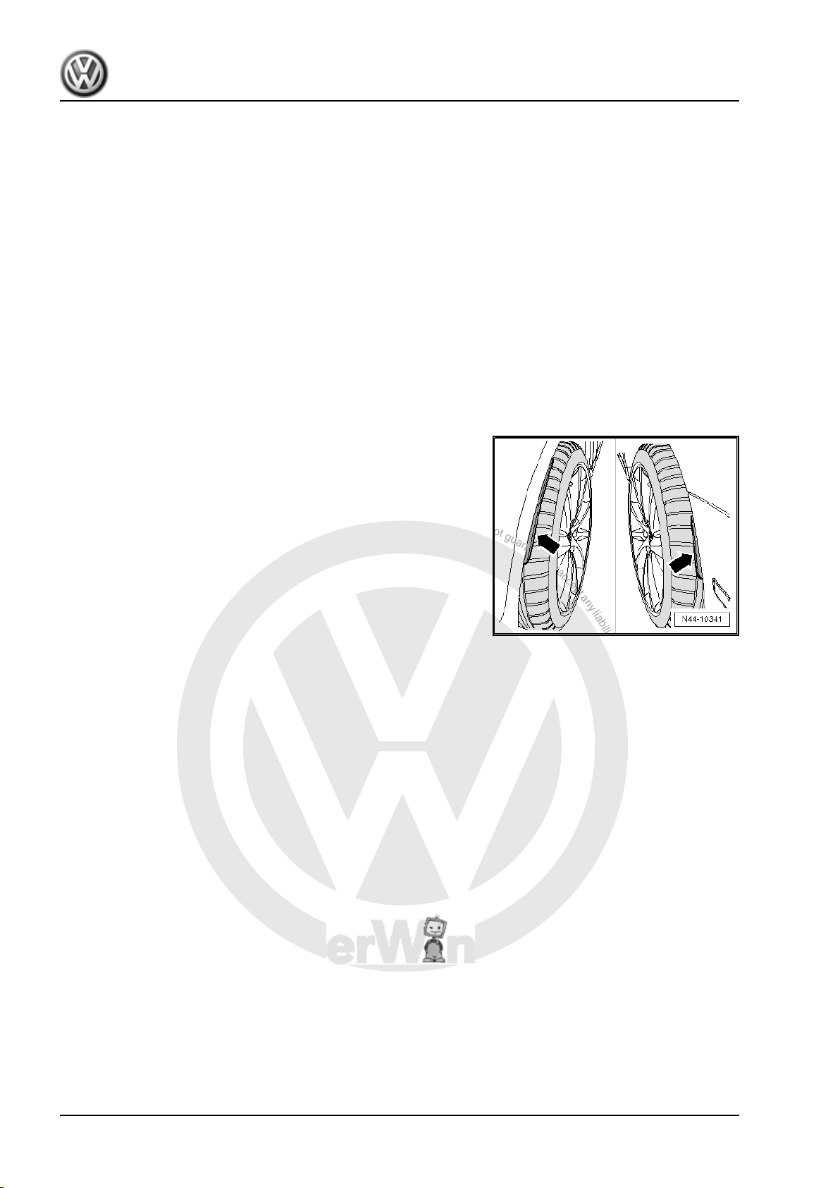
Note
Tyre damage and related problems can have various causes. It
is, therefore, very important that you determine whether the prob‐
lem has been caused by the tyre or by other components.
Normal wear and tear on a tyre will alter its characteristics. Rolling
noises or rough running can be the result of such wear. These are
simply the symptoms of normal wear and tear and do not consti‐
tute damage in the sense of the tyre being defective. You can take
measures to eliminate the symptoms at least to some degree.
However, in some cases it may not be possible to eliminate tyre
noise completely.
1. General notes on wheels and tyres (commercial vehicles) 1

P
r
o
t
e
c
t
e
d
b
y
c
o
p
y
r
i
g
h
t
.
C
o
p
y
i
n
g
f
o
r
p
r
i
v
a
t
e
o
r
c
o
m
m
e
r
c
i
a
l
p
u
r
p
o
s
e
s
,
i
n
p
a
r
t
o
r
i
n
w
h
o
l
e
,
i
s
n
o
t
p
e
r
m
i
t
t
e
d
u
n
l
e
s
s
a
u
t
h
o
r
i
s
e
d
b
y
V
o
l
k
s
w
a
g
e
n
A
G
.
V
o
l
k
s
w
a
g
e
n
A
G
d
o
e
s
n
o
t
g
u
a
r
a
n
t
e
e
o
r
a
c
c
e
p
t
a
n
y
l
i
a
b
i
l
i
t
y
w
i
t
h
r
e
s
p
e
c
t
t
o
t
h
e
c
o
r
r
e
c
t
n
e
s
s
o
f
i
n
f
o
r
m
a
t
i
o
n
i
n
t
h
i
s
d
o
c
u
m
e
n
t
.
C
o
p
y
r
i
g
h
t
b
y
V
o
l
k
s
w
a
g
e
n
A
G
.
Amarok 2011 ➤ , Caddy 2004 ➤ , Caddy 2011 ➤ , Caddy Kasten/Kombi 1996 ➤ ...
Wheels and Tyres Guide - Edition 11.2012
Special models
Special models are only partly represented in the tables in ap‐
pendix 2 or appendix for parts certificate. Modification of these
vehicles depends on the engine capacity of the basic model.
2 Rep. gr.44 - Wheels, tyres, vehicle geometry

P
r
o
t
e
c
t
e
d
b
y
c
o
p
y
r
i
g
h
t
.
C
o
p
y
i
n
g
f
o
r
p
r
i
v
a
t
e
o
r
c
o
m
m
e
r
c
i
a
l
p
u
r
p
o
s
e
s
,
i
n
p
a
r
t
o
r
i
n
w
h
o
l
e
,
i
s
n
o
t
p
e
r
m
i
t
t
e
d
u
n
l
e
s
s
a
u
t
h
o
r
i
s
e
d
b
y
V
o
l
k
s
w
a
g
e
n
A
G
.
V
o
l
k
s
w
a
g
e
n
A
G
d
o
e
s
n
o
t
g
u
a
r
a
n
t
e
e
o
r
a
c
c
e
p
t
a
n
y
l
i
a
b
i
l
i
t
y
w
i
t
h
r
e
s
p
e
c
t
t
o
t
h
e
c
o
r
r
e
c
t
n
e
s
s
o
f
i
n
f
o
r
m
a
t
i
o
n
i
n
t
h
i
s
d
o
c
u
m
e
n
t
.
C
o
p
y
r
i
g
h
t
b
y
V
o
l
k
s
w
a
g
e
n
A
G
.
Amarok 2011 ➤ , Caddy 2004 ➤ , Caddy 2011 ➤ , Caddy Kasten/Kombi 1996 ➤ ...
Wheels and Tyres Guide - Edition 11.2012
2 Legislative and technical conditions
for converting wheel and tyre combi‐
nations
2.1 Legislative conditions for converting wheel and tyre combinations
The manufacturer is issued with a general operating permit (GTA
in accordance with § 20 StVZO (German road traffic and licensing
regulations) and EU operating permit) for the overall vehicle with
all parts for specific conversions.
Conversions of wheels and tyres can only be carried out under
certain conditions. When doing this, the following points must be
observed:
♦ If the size of wheel and tyre, with an indication of the load index
and the speed symbol, is included in the vehicle GTA and EU
operating permit/type approval ⇒ page 6 , this wheel and
tyre combination can be fitted on the vehicle without any prob‐
lem.
It is not necessary for the wheel and tyre combination specified
in the registration certificate part I (certificate of registration) to be
fitted. All combinations approved in the vehicle GTA or EU oper‐
ating permit/type approval ⇒ page 6 may be fitted to the
vehicle.
♦ There is no general type approval according to § 22 StVZO for
the modifications recommended by Volkswagen AG (see at‐
tachment or Appendix 2 to Parts Certificate).
♦ Unless the wheels and/or tyres are included in the relevant
vehicle GTA or EU operating permit/type approval, the vehicle
will no longer meet the requirements of the road traffic regu‐
lations if converted.
These versions are based on the conditions valid in the European
Union and no guarantee can be provided for their completeness.
In some cases there are different legislative requirements outside
the European Union.
The table included in the attachment or Appendix 2 to Parts Cer‐
tificate shows the Volkswagen AG recommended and TÜV
NORD Mobilität GmbH Co. KG tested wheel and tyre combina‐
tions on VW vehicles and also the conditions to be observed for
fitting. The use of genuine disc-type wheels on a vehicle to which
they have not been allocated is not permissible.
The list of possible conversions deals with combinations that meet
the requirements of Volkswagen AG with regards to road handling
and road safety. They are the result of practical trials and are
therefore recommended by Volkswagen AG.
Refer also to the new vehicle registration documents that were
issued from 01.10.2005 ⇒ page 5 .
2.2 Technical conditions for converting wheel and tyre combinations
• The wheel and tyre combinations and conversions listed in the
tables of the individual vehicles refer exclusively to Volkswa‐
gen genuine wheels.
• Approval of wheel and tyre combinations or a change to
wheels from the accessories trade is not possible with the
parts certificate attached here.
2. Legislative and technical conditions for converting wheel and tyre combinations 3
P
r
o
t
e
c
t
e
d
b
y
c
o
p
y
r
i
g
h
t
.
C
o
p
y
i
n
g
f
o
r
p
r
i
v
a
t
e
o
r
c
o
m
m
e
r
c
i
a
l
p
u
r
p
o
s
e
s
,
i
n
p
a
r
t
o
r
i
n
w
h
o
l
e
,
i
s
n
o
t
p
e
r
m
i
t
t
e
d
u
n
l
e
s
s
a
u
t
h
o
r
i
s
e
d
b
y
V
o
l
k
s
w
a
g
e
n
A
G
.
V
o
l
k
s
w
a
g
e
n
A
G
d
o
e
s
n
o
t
g
u
a
r
a
n
t
e
e
o
r
a
c
c
e
p
t
a
n
y
l
i
a
b
i
l
i
t
y
w
i
t
h
r
e
s
p
e
c
t
t
o
t
h
e
c
o
r
r
e
c
t
n
e
s
s
o
f
i
n
f
o
r
m
a
t
i
o
n
i
n
t
h
i
s
d
o
c
u
m
e
n
t
.
C
o
p
y
r
i
g
h
t
b
y
V
o
l
k
s
w
a
g
e
n
A
G
.
Amarok 2011 ➤ , Caddy 2004 ➤ , Caddy 2011 ➤ , Caddy Kasten/Kombi 1996 ➤ ...
Wheels and Tyres Guide - Edition 11.2012
• Tubeless radial tyres may only be fitted to rims with a safety
hump feature on the shoulder.
• If the wheel and tyre combinations listed are used, the asso‐
ciated tyre inflation pressures must be adhered to. The tyre
inflation pressure for summer tyres can be found on the sticker
on the inside of the tank flap or in the tables of the individual
vehicles.
• Sufficient clearance to the wheels and tyres at parts of the
wheel housing, suspension and braking system is assured if
the notes and specifications established in the parts certificate
are observed in all operating conditions.
• Unless otherwise stated, snow chains may be fitted only to the
drive wheels.
• The same sized wheels and tyres must be used at the front
and rear of the vehicle. On vehicles with all-wheel drive, tyres
must be of the same manufacturer and have the same tread
profile.
2.3 Additional wheel housing extensions
For technical reasons, some vehicles require wheel housing ex‐
tensions on the wing or bumper -arrows- when using certain
wheel and tyre combinations.
Please check if there is a requirement to fit the extensions.
The information is located in the overview table for the respective
vehicle.
2.4 “Series 80” tyres
Tyres of the “80” series (e.g. 145/80 R 13 74 S) will replace the
“82” series (e.g. 145/82 R 13 74 S). Legislation stipulates that “82”
series tyres may be replaced by “80” series tyres without having
been entered in the vehicle documents.
The condition for this is that the “80” series tyres have the same
width are of the same type – cross-ply or radial belted – and have
the same or higher load index.
If only “80” series tyres are entered in the vehicle documents, “82”
series tyres may only be used if an entry has been made in the
vehicle documents.
4 Rep. gr.44 - Wheels, tyres, vehicle geometry

P
r
o
t
e
c
t
e
d
b
y
c
o
p
y
r
i
g
h
t
.
C
o
p
y
i
n
g
f
o
r
p
r
i
v
a
t
e
o
r
c
o
m
m
e
r
c
i
a
l
p
u
r
p
o
s
e
s
,
i
n
p
a
r
t
o
r
i
n
w
h
o
l
e
,
i
s
n
o
t
p
e
r
m
i
t
t
e
d
u
n
l
e
s
s
a
u
t
h
o
r
i
s
e
d
b
y
V
o
l
k
s
w
a
g
e
n
A
G
.
V
o
l
k
s
w
a
g
e
n
A
G
d
o
e
s
n
o
t
g
u
a
r
a
n
t
e
e
o
r
a
c
c
e
p
t
a
n
y
l
i
a
b
i
l
i
t
y
w
i
t
h
r
e
s
p
e
c
t
t
o
t
h
e
c
o
r
r
e
c
t
n
e
s
s
o
f
i
n
f
o
r
m
a
t
i
o
n
i
n
t
h
i
s
d
o
c
u
m
e
n
t
.
C
o
p
y
r
i
g
h
t
b
y
V
o
l
k
s
w
a
g
e
n
A
G
.
Amarok 2011 ➤ , Caddy 2004 ➤ , Caddy 2011 ➤ , Caddy Kasten/Kombi 1996 ➤ ...
Wheels and Tyres Guide - Edition 11.2012
3 Documents and codes/designations
3.1 New vehicle registration documents since 01.10.2005
The implementation of EU Directive 1999/37/EU "Registration
Documents for Vehicles" in national law and legal requirements
for data protection have necessitated the introduction of new, fal‐
sification-proof registration documents.
Since 01.10.2005, only the new documents are issued by the
registration authorities in the event of new registrations, change
of ownership, registration of technical modifications and all other
matters.
The new registration documents are comprised of:
♦ Registration certificate part I, which replaces the certificate of
registration and
♦ Registration certificate part II, which replaces the vehicle log
book.
Registration certificate part I (certificate of registration)
♦ Contains all vehicle technical data which must be available to
register a vehicle in Europe; however, only one wheel and tyre
combination approved as standard is specified
♦ Contains the EU-wide, standardised, alphanumerical codes
assigned to the technical data, so that the German registration
certificate can be converted without problems into the regis‐
tration document prescribed in other EU states for registration
there
♦ Contains a field for documenting temporary or final immobili‐
sation of the vehicle, and is therefore no longer withdrawn in
the event of temporary or final immobilisation.
Registration certificate part II (vehicle log book)
♦ Contains the note that the holder of the registration certificate
is not identified as the owner
♦ Contains only the current and, if applicable, the previous ve‐
hicle keeper; the actual number of former keepers is shown
numerically
♦ Contains only a small percentage of the technical vehicle data
♦ No longer serves to document temporary vehicle deregistra‐
tion. The vehicle and body type specified under number 1 in
the old vehicle documents will not exist in the future. In the new
documents, this will be replaced by standardised EU vehicle
classes with body type.
Introduction of the new registration documents will lead to barely
any changes for the vehicle operator.
Like the old certificate of registration, the registration certificate
part I (certificate of registration) must be kept in the vehicle and
submitted to responsible persons on request.
It is not necessary for the wheel and tyre combination specified
in the registration certificate part I (certificate of registration) to be
fitted. All combinations approved according to the general vehicle
type approval or EU type approval ⇒ page 6 may be fitted.
The validity of a wheel and tyre combination which deviates from
the general vehicle type approval or EU type approval must still
be verified via an entry in the registration certificate part I (certif‐
icate of registration), an installation certificate based on a part
3. Documents and codes/designations 5

P
r
o
t
e
c
t
e
d
b
y
c
o
p
y
r
i
g
h
t
.
C
o
p
y
i
n
g
f
o
r
p
r
i
v
a
t
e
o
r
c
o
m
m
e
r
c
i
a
l
p
u
r
p
o
s
e
s
,
i
n
p
a
r
t
o
r
i
n
w
h
o
l
e
,
i
s
n
o
t
p
e
r
m
i
t
t
e
d
u
n
l
e
s
s
a
u
t
h
o
r
i
s
e
d
b
y
V
o
l
k
s
w
a
g
e
n
A
G
.
V
o
l
k
s
w
a
g
e
n
A
G
d
o
e
s
n
o
t
g
u
a
r
a
n
t
e
e
o
r
a
c
c
e
p
t
a
n
y
l
i
a
b
i
l
i
t
y
w
i
t
h
r
e
s
p
e
c
t
t
o
t
h
e
c
o
r
r
e
c
t
n
e
s
s
o
f
i
n
f
o
r
m
a
t
i
o
n
i
n
t
h
i
s
d
o
c
u
m
e
n
t
.
C
o
p
y
r
i
g
h
t
b
y
V
o
l
k
s
w
a
g
e
n
A
G
.
Amarok 2011 ➤ , Caddy 2004 ➤ , Caddy 2011 ➤ , Caddy Kasten/Kombi 1996 ➤ ...
Wheels and Tyres Guide - Edition 11.2012
certificate or general type approval for the wheel and tyre combi‐
nation.
3.2 COC document (EEC Certificate of Con‐
formity)
Since 1 June, 2004, vehicle manufacturers must apply for an EU
operating permit.
A certificate is produced on the basis of this operating permit - the
COC (Certificate of Conformity).
This document certifies that the vehicle complies with the EU op‐
erating permit (EU type approval) and can be registered in every
EU country without an individual type approval.
The document will be issued for all vehicles that comply with the
EU operating permit.
These vehicles have an EU type plate (black sticker) in the area
of the driver's door, or in the case of older vehicles, in the engine
compartment.
The COC document has the same value as the registration docu‐
ment and therefore the original should not be carried on the
vehicle.
The COC document contains the EU general type approval num‐
ber and detailed technical information on the vehicle such as
emissions classification and all the permitted wheel and tyre com‐
binations.
6 Rep. gr.44 - Wheels, tyres, vehicle geometry

P
r
o
t
e
c
t
e
d
b
y
c
o
p
y
r
i
g
h
t
.
C
o
p
y
i
n
g
f
o
r
p
r
i
v
a
t
e
o
r
c
o
m
m
e
r
c
i
a
l
p
u
r
p
o
s
e
s
,
i
n
p
a
r
t
o
r
i
n
w
h
o
l
e
,
i
s
n
o
t
p
e
r
m
i
t
t
e
d
u
n
l
e
s
s
a
u
t
h
o
r
i
s
e
d
b
y
V
o
l
k
s
w
a
g
e
n
A
G
.
V
o
l
k
s
w
a
g
e
n
A
G
d
o
e
s
n
o
t
g
u
a
r
a
n
t
e
e
o
r
a
c
c
e
p
t
a
n
y
l
i
a
b
i
l
i
t
y
w
i
t
h
r
e
s
p
e
c
t
t
o
t
h
e
c
o
r
r
e
c
t
n
e
s
s
o
f
i
n
f
o
r
m
a
t
i
o
n
i
n
t
h
i
s
d
o
c
u
m
e
n
t
.
C
o
p
y
r
i
g
h
t
b
y
V
o
l
k
s
w
a
g
e
n
A
G
.
Amarok 2011 ➤ , Caddy 2004 ➤ , Caddy 2011 ➤ , Caddy Kasten/Kombi 1996 ➤ ...
Wheels and Tyres Guide - Edition 11.2012
4 Official type designations
Commercial vehicles licensed for road use in Germany need a
general type approval for the issue of a vehicle title document.
The type approval is issued by the Federal Ministry for Transport
in Flensburg following type inspection. This procedure was per‐
mitted until 31.12.1997 and, in exceptional cases, even after that.
Other member states of the European Union (EU) have different
procedures for issuing a document similar to the German title
document. Until 31.12.1997, each member state was entitled to
issue its own national type approvals according to its own proce‐
dures.
Since 1.1.1998, all commercial vehicles licensed within the Eu‐
ropean Union must have a type approval corresponding to EU
guidelines ⇒ page 7 . Vehicles licensed for road use with sin‐
gle-vehicle approval according to § 21 StVZO in Germany are
excepted.
This means the same guidelines apply to all vehicle manufactur‐
ers. This makes it easier to trade across national borders within
the EU.
4.1 Official type approval, sales or trade designation
In the following table, all VW vehicles which already have EU type
approval are listed in the column "EU type".
All VW vehicles which were granted type approval according to
the procedure valid up to 31.12.97 are listed in the column "Gen‐
eral type approval (GTA)"
If entries appear in both columns "General type approval (GTA)"
and "EU type", there exist vehicles of this model which are ap‐
proved according to both the StVZO and the EU guidelines. In this
case, one must first establish what sort of vehicle one has. There
are two possibilities:
1. possibility
The last page of the vehicle title includes the field “Certified holder
of a general type approval/EEC type approval”. Either the general
type approval number of the EU type approval number is entered
here, assuming it is the original vehicle title document. This is the
case only if the vehicle was not deregistered in the past for longer
than 12 months.
2. possibility
Check whether the general type approval number or the EU type
approval number is entered on the vehicle identification plate.
Official type designation for vehicles
Sales or trade designation
with
GTA type EU type
- 2H Amarok
- 2K Caddy Life 2004 > passenger vehicle
- 2KN Caddy 2004 > with goods vehicle registration
- 9KV Caddy (Kombi)
9KVF - Caddy (panel van)
9U - Caddy (pickup)
70X0A/70X02A - Transporter panel van (T4)
70X0B - Multivan (T4)
70X02B 7DW Camper (T4)
- 7DB Multivan (T4)
4. Official type designations 7

P
r
o
t
e
c
t
e
d
b
y
c
o
p
y
r
i
g
h
t
.
C
o
p
y
i
n
g
f
o
r
p
r
i
v
a
t
e
o
r
c
o
m
m
e
r
c
i
a
l
p
u
r
p
o
s
e
s
,
i
n
p
a
r
t
o
r
i
n
w
h
o
l
e
,
i
s
n
o
t
p
e
r
m
i
t
t
e
d
u
n
l
e
s
s
a
u
t
h
o
r
i
s
e
d
b
y
V
o
l
k
s
w
a
g
e
n
A
G
.
V
o
l
k
s
w
a
g
e
n
A
G
d
o
e
s
n
o
t
g
u
a
r
a
n
t
e
e
o
r
a
c
c
e
p
t
a
n
y
l
i
a
b
i
l
i
t
y
w
i
t
h
r
e
s
p
e
c
t
t
o
t
h
e
c
o
r
r
e
c
t
n
e
s
s
o
f
i
n
f
o
r
m
a
t
i
o
n
i
n
t
h
i
s
d
o
c
u
m
e
n
t
.
C
o
p
y
r
i
g
h
t
b
y
V
o
l
k
s
w
a
g
e
n
A
G
.
Amarok 2011 ➤ , Caddy 2004 ➤ , Caddy 2011 ➤ , Caddy Kasten/Kombi 1996 ➤ ...
Wheels and Tyres Guide - Edition 11.2012
Official type designation for vehicles
Sales or trade designation
with
GTA type EU type
70X0BL - Camper (T4)
70X02BL 7DW Camper (T4)
70X0BN/
- Ambulance (T4)
70X02BN
70X0C - Caravelle; kombi; bus (T4)
70X02C 7DB Caravelle; kombi; bus (T4)
70X0D/70X02D - Dropside; double cab; chassis cab (T4)
70X1A/70X12A - Transporter Syncro panel van (T4)
70X1B - Multivan Syncro (T4)
70X12B 7DW Camper Syncro (T4)
- 7DWA Camper (M1)
- 7DWA Camper (M1) Syncro
- 7DB Multivan Syncro (T4)
70X1BL - Camper Syncro (T4)
70X12BL 7DW Camper Syncro (T4)
70X1BN/
- Ambulance Syncro (T4)
70X12BN
70X1C - Caravelle Syncro; kombi; bus (T4)
70X12C 7DB Caravelle Syncro; kombi; bus (T4)
70X1D/70X12D - Dropside; double cab; chassis cab (T4)
- 7DZ Multivan, Caravelle (with 16 inch)
- 7DZA Camper (M1 16 inch)
7J0 - Transporter 2004 > goods vehicle registered dropside; double cab;
- 7HM Transporter 2004 > Multivan, Multivan 4MOTION, Business, Multi‐
- 7HMA Transporter 2004 > California camper
- 7HC Transporter 2004 > Transporter passenger vehicle
- 7HCA Transporter 2004 > Transporter passenger vehicle 4MOTION
7HK - Transporter 2004 > goods vehicle registered panel van
7HKX0 - Transporter 2004 > goods vehicle registered panel van 4MOTION
2DX0AE - LT 28/35 panel van, single wheel
2DX0FE - LT 28/35 dropside; double cab; chassis cab, single wheel
2DX0AZ - LT 35/46 panel van, twin wheel
2DX0FZ - LT 35/46 dropside; double cab; chassis cab, twin wheel
- 2DM LT 28/35 kombi, single wheel
- 2EC1 Crafter 2006 > Kombi
- 2EC2 Crafter 2006 > Kombi
2EKE1 - Crafter 2006 > panel van
2EKE2 - Crafter 2006 > panel van
chassis cab
Transporter 2004 > goods vehicle registered dropside; double cab;
chassis cab 4MOTION
van Beach, Multivan Startline
2EKZ - Crafter 2006 > panel van
2FJE1 - Crafter 2006 > vehicle chassis, dropside
2FJE2 - Crafter 2006 > vehicle chassis, dropside
2FJZ - Crafter 2006 > vehicle chassis, dropside
8 Rep. gr.44 - Wheels, tyres, vehicle geometry

P
r
o
t
e
c
t
e
d
b
y
c
o
p
y
r
i
g
h
t
.
C
o
p
y
i
n
g
f
o
r
p
r
i
v
a
t
e
o
r
c
o
m
m
e
r
c
i
a
l
p
u
r
p
o
s
e
s
,
i
n
p
a
r
t
o
r
i
n
w
h
o
l
e
,
i
s
n
o
t
p
e
r
m
i
t
t
e
d
u
n
l
e
s
s
a
u
t
h
o
r
i
s
e
d
b
y
V
o
l
k
s
w
a
g
e
n
A
G
.
V
o
l
k
s
w
a
g
e
n
A
G
d
o
e
s
n
o
t
g
u
a
r
a
n
t
e
e
o
r
a
c
c
e
p
t
a
n
y
l
i
a
b
i
l
i
t
y
w
i
t
h
r
e
s
p
e
c
t
t
o
t
h
e
c
o
r
r
e
c
t
n
e
s
s
o
f
i
n
f
o
r
m
a
t
i
o
n
i
n
t
h
i
s
d
o
c
u
m
e
n
t
.
C
o
p
y
r
i
g
h
t
b
y
V
o
l
k
s
w
a
g
e
n
A
G
.
Amarok 2011 ➤ , Caddy 2004 ➤ , Caddy 2011 ➤ , Caddy Kasten/Kombi 1996 ➤ ...
Wheels and Tyres Guide - Edition 11.2012
4. Official type designations 9
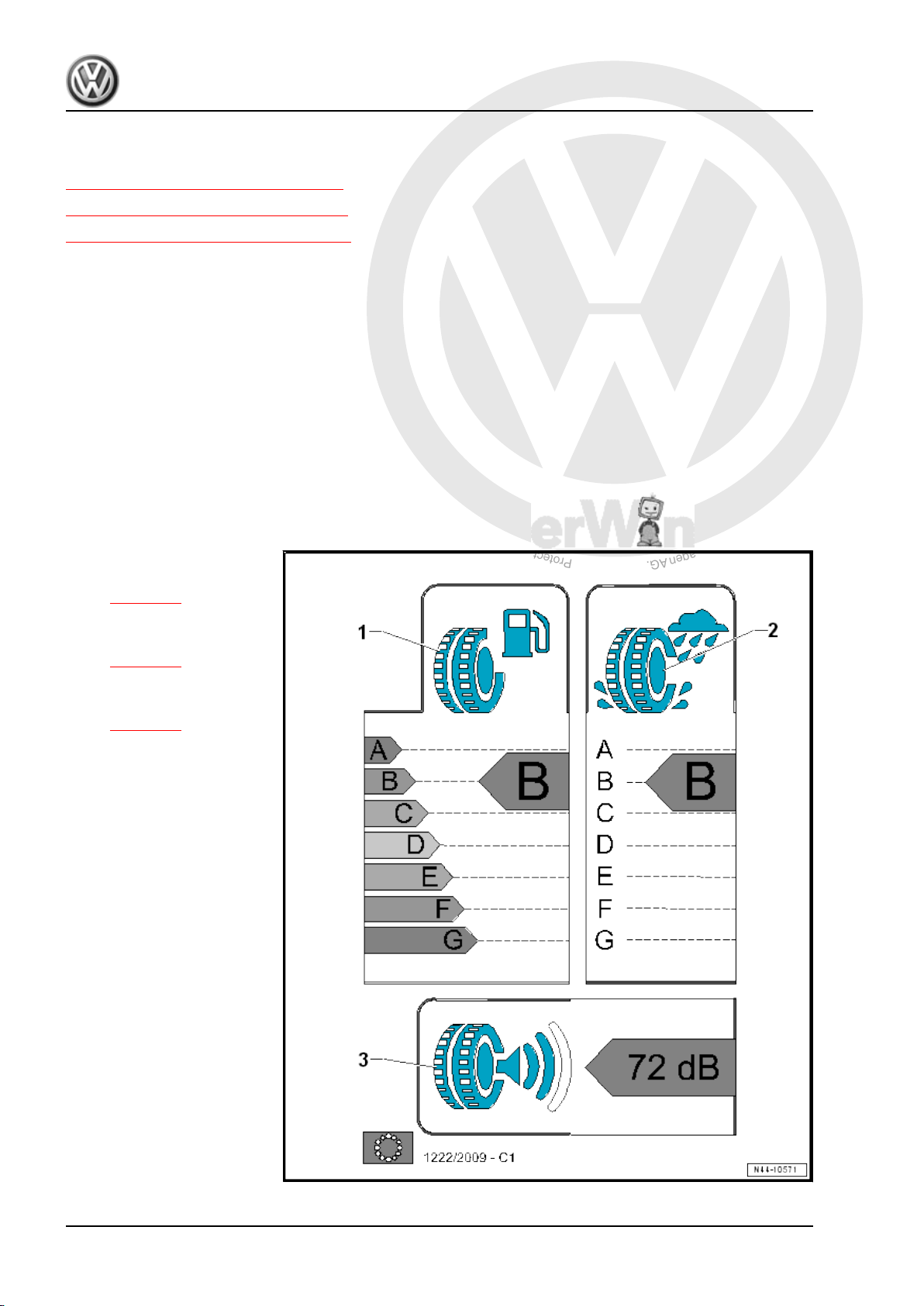
P
r
o
t
e
c
t
e
d
b
y
c
o
p
y
r
i
g
h
t
.
C
o
p
y
i
n
g
f
o
r
p
r
i
v
a
t
e
o
r
c
o
m
m
e
r
c
i
a
l
p
u
r
p
o
s
e
s
,
i
n
p
a
r
t
o
r
i
n
w
h
o
l
e
,
i
s
n
o
t
p
e
r
m
i
t
t
e
d
u
n
l
e
s
s
a
u
t
h
o
r
i
s
e
d
b
y
V
o
l
k
s
w
a
g
e
n
A
G
.
V
o
l
k
s
w
a
g
e
n
A
G
d
o
e
s
n
o
t
g
u
a
r
a
n
t
e
e
o
r
a
c
c
e
p
t
a
n
y
l
i
a
b
i
l
i
t
y
w
i
t
h
r
e
s
p
e
c
t
t
o
t
h
e
c
o
r
r
e
c
t
n
e
s
s
o
f
i
n
f
o
r
m
a
t
i
o
n
i
n
t
h
i
s
d
o
c
u
m
e
n
t
.
C
o
p
y
r
i
g
h
t
b
y
V
o
l
k
s
w
a
g
e
n
A
G
.
Amarok 2011 ➤ , Caddy 2004 ➤ , Caddy 2011 ➤ , Caddy Kasten/Kombi 1996 ➤ ...
Wheels and Tyres Guide - Edition 11.2012
5 EU tyre label
⇒ “5.1 EU tyre label, summary”, page 10
⇒ “5.2 EU tyre label, objectives”, page 11
⇒ “5.3 EU tyre label, categories”, page 12
5.1 EU tyre label, summary
Tyre manufactures must mark their tyres according to EU regu‐
lation (EC) No. 1222/2009 (labelling of tyres) as of 01 November
2012.
The labelling of tyres regulation contains the requirements refer‐
ence markings and representation of information for rolling re‐
sistance (fuel efficiency), wet grip and external rolling noise on a
standard and approved EU label. The objective is to increase
safety and economic and environmental efficiency of road trans‐
port by promoting fuel efficient and safe tyres with low noise
levels.
The new EU tyre label contains specified data in seven categories
from A to G.
There are three different categories:
1 - Rolling resistance
❑ Explanations
⇒ page 12
2 - Wet grip
❑ Explanations
⇒ page 13
3 - Noise emissions
❑ Explanations
⇒ page 14
10 Rep. gr.44 - Wheels, tyres, vehicle geometry

P
r
o
t
e
c
t
e
d
b
y
c
o
p
y
r
i
g
h
t
.
C
o
p
y
i
n
g
f
o
r
p
r
i
v
a
t
e
o
r
c
o
m
m
e
r
c
i
a
l
p
u
r
p
o
s
e
s
,
i
n
p
a
r
t
o
r
i
n
w
h
o
l
e
,
i
s
n
o
t
p
e
r
m
i
t
t
e
d
u
n
l
e
s
s
a
u
t
h
o
r
i
s
e
d
b
y
V
o
l
k
s
w
a
g
e
n
A
G
.
V
o
l
k
s
w
a
g
e
n
A
G
d
o
e
s
n
o
t
g
u
a
r
a
n
t
e
e
o
r
a
c
c
e
p
t
a
n
y
l
i
a
b
i
l
i
t
y
w
i
t
h
r
e
s
p
e
c
t
t
o
t
h
e
c
o
r
r
e
c
t
n
e
s
s
o
f
i
n
f
o
r
m
a
t
i
o
n
i
n
t
h
i
s
d
o
c
u
m
e
n
t
.
C
o
p
y
r
i
g
h
t
b
y
V
o
l
k
s
w
a
g
e
n
A
G
.
Amarok 2011 ➤ , Caddy 2004 ➤ , Caddy 2011 ➤ , Caddy Kasten/Kombi 1996 ➤ ...
Wheels and Tyres Guide - Edition 11.2012
5.2 EU tyre label, objectives
♦ Reducing fuel consumption
♦ Increasing road safety
♦ Reducing traffic noise
The EU tyre label provides the end-user with important informa‐
tion on the properties of the tyre. It does not illustrate, however,
all decisive safety criteria.
♦ The explanation of other properties of the tyre may influence
the decision to purchase.
♦ The customer should be advised of the limited information on
the label of tyre properties, such as no information concerning
winter properties for winter tyres.
♦ Tyre tests are another source of information for specialist
dealers and end-users.
In the tyres tests other leading factors are also tested, which
should be taken into account:
♦ Aquaplaning properties
♦ Driving stability
♦ Steering precision
♦ Service life
♦ Braking properties
♦ Behaviour in winterly conditions
5. EU tyre label 11

P
r
o
t
e
c
t
e
d
b
y
c
o
p
y
r
i
g
h
t
.
C
o
p
y
i
n
g
f
o
r
p
r
i
v
a
t
e
o
r
c
o
m
m
e
r
c
i
a
l
p
u
r
p
o
s
e
s
,
i
n
p
a
r
t
o
r
i
n
w
h
o
l
e
,
i
s
n
o
t
p
e
r
m
i
t
t
e
d
u
n
l
e
s
s
a
u
t
h
o
r
i
s
e
d
b
y
V
o
l
k
s
w
a
g
e
n
A
G
.
V
o
l
k
s
w
a
g
e
n
A
G
d
o
e
s
n
o
t
g
u
a
r
a
n
t
e
e
o
r
a
c
c
e
p
t
a
n
y
l
i
a
b
i
l
i
t
y
w
i
t
h
r
e
s
p
e
c
t
t
o
t
h
e
c
o
r
r
e
c
t
n
e
s
s
o
f
i
n
f
o
r
m
a
t
i
o
n
i
n
t
h
i
s
d
o
c
u
m
e
n
t
.
C
o
p
y
r
i
g
h
t
b
y
V
o
l
k
s
w
a
g
e
n
A
G
.
Amarok 2011 ➤ , Caddy 2004 ➤ , Caddy 2011 ➤ , Caddy Kasten/Kombi 1996 ➤ ...
Wheels and Tyres Guide - Edition 11.2012
5.3 EU tyre label, categories
⇒ “5.3.1 EU tyre label, categories, rolling resistance”, page 12
⇒ “5.3.2 EU tyre label, categories, wet grip”, page 13
⇒ “5.3.3 EU tyre label, categories, noise emissions”, page 14
5.3.1 EU tyre label, categories, rolling resist‐
ance
Definition
Rolling resistance:
♦ Defined as, energy consumed by the tyre in respect of the
distance travelled.
♦ Equates to the energy lost per defined unit of distance travel‐
led.
♦ The energy form can be described as the quotient of Newton
meter (Nm) and distance travelled in meter (m). This then pro‐
vides a rolling resistance as a form of force in Newtons (N).
The rolling resistance of a tyre is then described by the coefficient
of rolling resistance (also known as rolling resistance coefficient)
cR:
cR = FR Z
♦ cR - coefficient of rolling resistance
♦ FR - force of rolling resistance
♦ Z - weight of vehicle (sum of all wheel loads)
Objective
♦ Reduction of rolling resistance
♦ Reduction of fuel and CO
Evaluation
♦ Structured in fuel efficiency categories from A to G
♦ Category D is not used
Note
♦
The fuel efficiency category is listed in EU regulation (EC) No.
1222/2009, the tyre is then allocated to the respective cate‐
gory.
♦
The rolling resistance is established by the tyre manufacture
via prescribed tests.
♦
The lower the rolling resistance, the lower the fuel consump‐
2
tion.
A - Lowest rolling resistance = lowest fuel consumption
B - + 0.10 l / 100 km
C - + 0.12 l / 100 km
E - + 0.14 l / 100 km
F - + 0.15 l / 100 km
G - + 0.15 l / 100 km
12 Rep. gr.44 - Wheels, tyres, vehicle geometry

P
r
o
t
e
c
t
e
d
b
y
c
o
p
y
r
i
g
h
t
.
C
o
p
y
i
n
g
f
o
r
p
r
i
v
a
t
e
o
r
c
o
m
m
e
r
c
i
a
l
p
u
r
p
o
s
e
s
,
i
n
p
a
r
t
o
r
i
n
w
h
o
l
e
,
i
s
n
o
t
p
e
r
m
i
t
t
e
d
u
n
l
e
s
s
a
u
t
h
o
r
i
s
e
d
b
y
V
o
l
k
s
w
a
g
e
n
A
G
.
V
o
l
k
s
w
a
g
e
n
A
G
d
o
e
s
n
o
t
g
u
a
r
a
n
t
e
e
o
r
a
c
c
e
p
t
a
n
y
l
i
a
b
i
l
i
t
y
w
i
t
h
r
e
s
p
e
c
t
t
o
t
h
e
c
o
r
r
e
c
t
n
e
s
s
o
f
i
n
f
o
r
m
a
t
i
o
n
i
n
t
h
i
s
d
o
c
u
m
e
n
t
.
C
o
p
y
r
i
g
h
t
b
y
V
o
l
k
s
w
a
g
e
n
A
G
.
Amarok 2011 ➤ , Caddy 2004 ➤ , Caddy 2011 ➤ , Caddy Kasten/Kombi 1996 ➤ ...
Wheels and Tyres Guide - Edition 11.2012
5.3.2 EU tyre label, categories, wet grip
Definition
The wet grip index G must be established for the wet grip. The
wet grip index G is established using a deceleration test (distance
required to decelerate from 80 km/h to 20 km/h) using a standar‐
dised vehicle on a wet slippery surface. The test uses a prede‐
fined standard reference test tyre (SRTT), with which the wet grip
index G can be calculated. The calculation uses the mean fully
developed deceleration (mfdd) produced.
The mean fully developed deceleration (mfdd) is calculated as
follows:
mfdd = 231,48S
S - the measured braking distance in metres between 80 km/h
and 20 km/h
The wet grip index G is calculated as follows:
G = mfdd des zu prüfenden Reifensmfdd des Standard-Ref‐
erenzreifens
mffd - mean fully developed deceleration
Objective
♦ Good wet grip of tyre
♦ Greatly reduced bake distance
Evaluation
♦ Structured in wet grip categories from A to G
♦ Categories D and G are not used
Note
♦
The wet grip category is listed in EU regulation (EC) No.
1222/2009, the tyre is then allocated to the respective cate‐
gory.
♦
The lower the wet grip index, the shorter the braking distance.
A - Lowest wet grip index = shortest braking distance
B - 3 to 6 m longer braking distance in comparison with category
A
C - 3 to 6 m longer braking distance in comparison with category
B
E - 3 to 6 m longer braking distance in comparison with category
C
F - 3 to 6 m longer braking distance in comparison with category
E
1 - The braking distance between categories A and F can be more
than 18 m when undertaking an emergency stop at 80 km/h.
5. EU tyre label 13
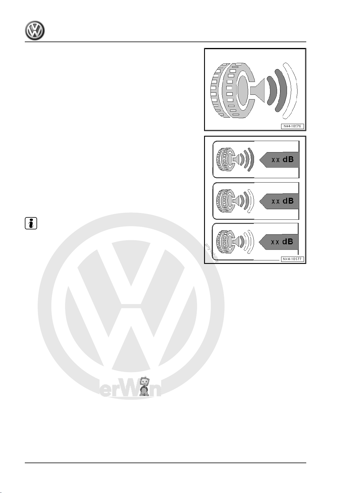
P
r
o
t
e
c
t
e
d
b
y
c
o
p
y
r
i
g
h
t
.
C
o
p
y
i
n
g
f
o
r
p
r
i
v
a
t
e
o
r
c
o
m
m
e
r
c
i
a
l
p
u
r
p
o
s
e
s
,
i
n
p
a
r
t
o
r
i
n
w
h
o
l
e
,
i
s
n
o
t
p
e
r
m
i
t
t
e
d
u
n
l
e
s
s
a
u
t
h
o
r
i
s
e
d
b
y
V
o
l
k
s
w
a
g
e
n
A
G
.
V
o
l
k
s
w
a
g
e
n
A
G
d
o
e
s
n
o
t
g
u
a
r
a
n
t
e
e
o
r
a
c
c
e
p
t
a
n
y
l
i
a
b
i
l
i
t
y
w
i
t
h
r
e
s
p
e
c
t
t
o
t
h
e
c
o
r
r
e
c
t
n
e
s
s
o
f
i
n
f
o
r
m
a
t
i
o
n
i
n
t
h
i
s
d
o
c
u
m
e
n
t
.
C
o
p
y
r
i
g
h
t
b
y
V
o
l
k
s
w
a
g
e
n
A
G
.
Amarok 2011 ➤ , Caddy 2004 ➤ , Caddy 2011 ➤ , Caddy Kasten/Kombi 1996 ➤ ...
Wheels and Tyres Guide - Edition 11.2012
5.3.3 EU tyre label, categories, noise emis‐
sions
Objective
♦ Reduction of pass-by noise
♦ Reducing noise emissions
Evaluation
♦ Measured on outside of vehicle only
♦ Divided into three categories
♦ Three black arcs indicate the worst performance. The tyres
produce a rolling noise that lies below the current limit accord‐
ing to EU regulation 2001/43/EG. The limit lies above the limit
that has been set for from 2016 according to regulation (EG)
No. 661/2009.
♦ Two black arcs: The tyre noise limit lies below the limit that has
been set for from 2016 according to regulation (EG) No.
661/2009.
♦ One black arc: The tyre noise limit lies below the limit that has
been set for from 2016 according to regulation (EG) No.
661/2009, by at least three decibels.
Note
♦
Reducing the noise level from two arcs to one arc equates to
3 dB, which halves the noise level.
♦
Note, the external rolling noise of the tyre does not always
correspond with the noise in the vehicle interior.
14 Rep. gr.44 - Wheels, tyres, vehicle geometry
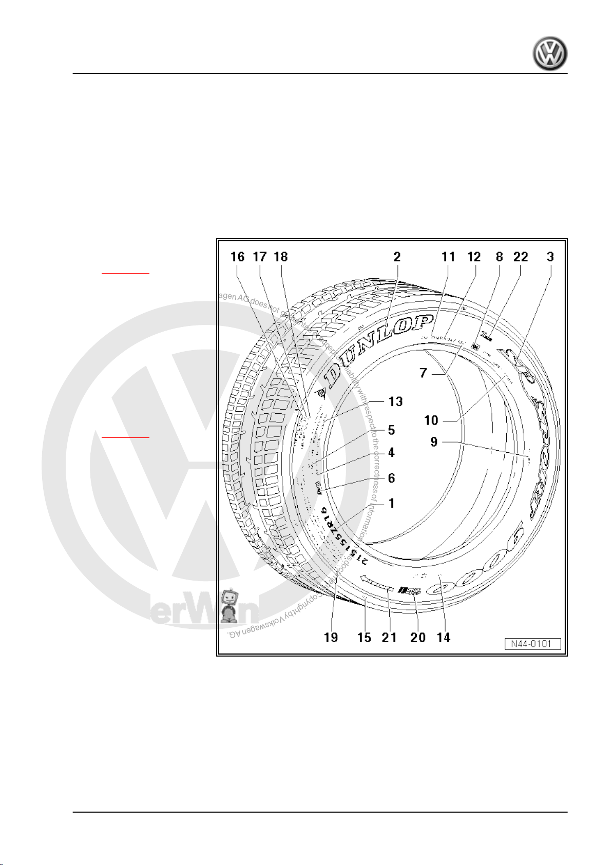
P
r
o
t
e
c
t
e
d
b
y
c
o
p
y
r
i
g
h
t
.
C
o
p
y
i
n
g
f
o
r
p
r
i
v
a
t
e
o
r
c
o
m
m
e
r
c
i
a
l
p
u
r
p
o
s
e
s
,
i
n
p
a
r
t
o
r
i
n
w
h
o
l
e
,
i
s
n
o
t
p
e
r
m
i
t
t
e
d
u
n
l
e
s
s
a
u
t
h
o
r
i
s
e
d
b
y
V
o
l
k
s
w
a
g
e
n
A
G
.
V
o
l
k
s
w
a
g
e
n
A
G
d
o
e
s
n
o
t
g
u
a
r
a
n
t
e
e
o
r
a
c
c
e
p
t
a
n
y
l
i
a
b
i
l
i
t
y
w
i
t
h
r
e
s
p
e
c
t
t
o
t
h
e
c
o
r
r
e
c
t
n
e
s
s
o
f
i
n
f
o
r
m
a
t
i
o
n
i
n
t
h
i
s
d
o
c
u
m
e
n
t
.
C
o
p
y
r
i
g
h
t
b
y
V
o
l
k
s
w
a
g
e
n
A
G
.
Amarok 2011 ➤ , Caddy 2004 ➤ , Caddy 2011 ➤ , Caddy Kasten/Kombi 1996 ➤ ...
Wheels and Tyres Guide - Edition 11.2012
6 Facts about wheels and tyres (com‐
mercial vehicles)
6.1 Useful information regarding tyres
6.1.1 Identification markings on the tyre sidewall
Example: Dunlop SP Sport 9000
1 - Size code
❑ e.g. 195/65 R 15 91T
⇒ page 16
2 - Manufacturer (trade name)
3 - Tread pattern
4 - Code for tubeless tyres
5 - Radial construction
❑ Radial cord direction in
6 - Notes for version with “rim
protector”
7 - Production date
❑ Tyre ageing
8 - E number = Approval num‐
ber
❑ Tyre meets European
9 - Country of origin
❑ e.g. manufactured in
10 - Internal DUNLOP tread
code
11 - DOT - Department of
Transportation
❑ Tyre fulfils standards of
carcass
⇒ page 20
guidelines ECE-R30
and EEC92/93.
Germany
the Department of
Transportation of the
United States of Ameri‐
ca.
12 - DOT Code
❑ Identification number for manufacturer's plant, tyre size and tyre model
13 - Maximum permitted load and maximum permitted tyre pressure
❑ Data for North America
14 - Number of plies in the centre of the tread and in the sidewalls as well as information about the material
15 - Position of TWIs (Tread Wear Indicators)
16 - Relative expected service life - abrasion resistance
❑ based on a US standard test
6. Facts about wheels and tyres (commercial vehicles) 15

P
r
o
t
e
c
t
e
d
b
y
c
o
p
y
r
i
g
h
t
.
C
o
p
y
i
n
g
f
o
r
p
r
i
v
a
t
e
o
r
c
o
m
m
e
r
c
i
a
l
p
u
r
p
o
s
e
s
,
i
n
p
a
r
t
o
r
i
n
w
h
o
l
e
,
i
s
n
o
t
p
e
r
m
i
t
t
e
d
u
n
l
e
s
s
a
u
t
h
o
r
i
s
e
d
b
y
V
o
l
k
s
w
a
g
e
n
A
G
.
V
o
l
k
s
w
a
g
e
n
A
G
d
o
e
s
n
o
t
g
u
a
r
a
n
t
e
e
o
r
a
c
c
e
p
t
a
n
y
l
i
a
b
i
l
i
t
y
w
i
t
h
r
e
s
p
e
c
t
t
o
t
h
e
c
o
r
r
e
c
t
n
e
s
s
o
f
i
n
f
o
r
m
a
t
i
o
n
i
n
t
h
i
s
d
o
c
u
m
e
n
t
.
C
o
p
y
r
i
g
h
t
b
y
V
o
l
k
s
w
a
g
e
n
A
G
.
Amarok 2011 ➤ , Caddy 2004 ➤ , Caddy 2011 ➤ , Caddy Kasten/Kombi 1996 ➤ ...
Wheels and Tyres Guide - Edition 11.2012
17 - Rating of wet-braking traction, A, B or C
❑ According to a US test
18 - Rating of temperature resistance, A, B or C
❑ According to a US test
19 - Safety notes for use or fitting of tyre
20 - Reference to “ultralight construction”
❑ Tyre is up to 30% lighter.
21 - Specified direction of rotation for tyre
22 - Inmetro code
❑ Required for the Brazilian market only
6.1.2 Explanation of tyre lettering
Explanation of tyre dimensions
Tyres Speed 1 2 3 4 5 6 7
Summer tyres to 240 km/h 195 65 R 15 91 V -
Winter tyres to 160 km/h 195 65 R 15 91 Q M + S
Winter tyres to 190 km/h 195 65 R 15 91 T M + S
High-speed tyres faster than 240
km/h
225 50 ZR 16 91 - -
1 - Tyre width
2 - Aspect ratio in %
3 - Code for tyre construction: “R” indicates radial
4 - Rim diameter designation
5 - Load rating code/load index (LI)
6 - Speed rating code
7 - Winter tyre/code for all-season tyre
Speed rating/maximum speed
Speed rating code Maximum speed in km/h
L 120
M 130
N 140
P 150
Q 160
R 170
S 180
T 190
U 200
H 210
V 240
ZR above 240
W 270
Y 300
16 Rep. gr.44 - Wheels, tyres, vehicle geometry
P
r
o
t
e
c
t
e
d
b
y
c
o
p
y
r
i
g
h
t
.
C
o
p
y
i
n
g
f
o
r
p
r
i
v
a
t
e
o
r
c
o
m
m
e
r
c
i
a
l
p
u
r
p
o
s
e
s
,
i
n
p
a
r
t
o
r
i
n
w
h
o
l
e
,
i
s
n
o
t
p
e
r
m
i
t
t
e
d
u
n
l
e
s
s
a
u
t
h
o
r
i
s
e
d
b
y
V
o
l
k
s
w
a
g
e
n
A
G
.
V
o
l
k
s
w
a
g
e
n
A
G
d
o
e
s
n
o
t
g
u
a
r
a
n
t
e
e
o
r
a
c
c
e
p
t
a
n
y
l
i
a
b
i
l
i
t
y
w
i
t
h
r
e
s
p
e
c
t
t
o
t
h
e
c
o
r
r
e
c
t
n
e
s
s
o
f
i
n
f
o
r
m
a
t
i
o
n
i
n
t
h
i
s
d
o
c
u
m
e
n
t
.
C
o
p
y
r
i
g
h
t
b
y
V
o
l
k
s
w
a
g
e
n
A
G
.
Amarok 2011 ➤ , Caddy 2004 ➤ , Caddy 2011 ➤ , Caddy Kasten/Kombi 1996 ➤ ...
Wheels and Tyres Guide - Edition 11.2012
Load rating code/load index (LI)
The load rating can be found on the sidewall of the tyre. It provides
information about the maximum load that the tyre can bear.
The load rating is included in the size designation of the tyre (e.g.
195/65 R 15 91T). It is indicated on the tyre as a code according
to ETRTO. The following table shows the load rating codes used
at VW with the corresponding load capacity of the tyres.
Load rating code Maximum load of tyre in kg
75 387
78 425
79 437
80 450
81 462
82 475
83 487
84 500
85 515
86 530
87 545
88 560
89 580
90 600
91 615
92 630
93 650
94 670
95 690
96 710
97 730
98 750
99 775
100 800
101 825
102 850
103 875
104 900
110 1060
112 1120
113 1150
114 1180
115 1215
116 1250
117 1285
6. Facts about wheels and tyres (commercial vehicles) 17
P
r
o
t
e
c
t
e
d
b
y
c
o
p
y
r
i
g
h
t
.
C
o
p
y
i
n
g
f
o
r
p
r
i
v
a
t
e
o
r
c
o
m
m
e
r
c
i
a
l
p
u
r
p
o
s
e
s
,
i
n
p
a
r
t
o
r
i
n
w
h
o
l
e
,
i
s
n
o
t
p
e
r
m
i
t
t
e
d
u
n
l
e
s
s
a
u
t
h
o
r
i
s
e
d
b
y
V
o
l
k
s
w
a
g
e
n
A
G
.
V
o
l
k
s
w
a
g
e
n
A
G
d
o
e
s
n
o
t
g
u
a
r
a
n
t
e
e
o
r
a
c
c
e
p
t
a
n
y
l
i
a
b
i
l
i
t
y
w
i
t
h
r
e
s
p
e
c
t
t
o
t
h
e
c
o
r
r
e
c
t
n
e
s
s
o
f
i
n
f
o
r
m
a
t
i
o
n
i
n
t
h
i
s
d
o
c
u
m
e
n
t
.
C
o
p
y
r
i
g
h
t
b
y
V
o
l
k
s
w
a
g
e
n
A
G
.
Amarok 2011 ➤ , Caddy 2004 ➤ , Caddy 2011 ➤ , Caddy Kasten/Kombi 1996 ➤ ...
Wheels and Tyres Guide - Edition 11.2012
6.1.3 Speed ratings for tyres
The speed rating (e.g. “T”) following the size of the tyre (e.g.
185/65 R 14 86T)) indicates the maximum permitted speed
(v
) of the tyre.
max
The tyres for the vehicle must be selected so that their maximum
permitted speed is greater than the maximum speed that the ve‐
hicle (“based on model”) can attain.
Vehicles with national type approval
If the vehicle has a national type approval, the maximum speed
for the vehicle is calculated as follows:
Formula for vehicles with v
v
= 1.03 x v + 3.5 km/h ⇒ page 18
max
Example: specified maximum speed v = 145 km/h
v
= 1.03 x 145 km/h + 3.5 km/h = 152.85 km/h
max
In this example, a tyre with the speed rating “Q” or higher must
be used.
Formula for vehicles with v
v
= 1.01 x v + 6.5 km/h ⇒ page 18
max
Example: specified maximum speed v = 163 km/h
v
= 1.01 x 163 km/h + 6.5 km/h = 171.13 km/h
max
up to 150 km/h
max
above 151 km/h
max
In this example, a tyre with the speed rating “S” or higher must be
used.
Vehicles with EC type approval
If your vehicle has an EC type approval, the maximum speed for
all vehicles is calculated as follows:
v
= 1.05 x v ⇒ page 18
max
Example: specified maximum speed v = 172 km/h
v
= 1.05 x 172 km/h 180.60 km/h
max
In this example, a tyre with the speed rating “T” or higher must be
used.
It is permitted to use tyres with a higher speed rating. The same
applies to tyres with a higher load index.
Note
For the letter “v”, enter the maximum speed given in field “T” of
part I or II of the registration document or under number 6 of the
vehicle documentation. This calculation is necessary because all
vehicles, for technical reasons, achieve different maximum
speeds within a legally permitted tolerance.
6.1.4 Undulations
Radial depressions are slight concavities in the tyre sidewall.
They run from the bead towards the shoulder of the tyre. These
parts appear in the figure ⇒ page 44 .
The cause is the accumulation of material at the joints of the tyre
components.
18 Rep. gr.44 - Wheels, tyres, vehicle geometry
P
r
o
t
e
c
t
e
d
b
y
c
o
p
y
r
i
g
h
t
.
C
o
p
y
i
n
g
f
o
r
p
r
i
v
a
t
e
o
r
c
o
m
m
e
r
c
i
a
l
p
u
r
p
o
s
e
s
,
i
n
p
a
r
t
o
r
i
n
w
h
o
l
e
,
i
s
n
o
t
p
e
r
m
i
t
t
e
d
u
n
l
e
s
s
a
u
t
h
o
r
i
s
e
d
b
y
V
o
l
k
s
w
a
g
e
n
A
G
.
V
o
l
k
s
w
a
g
e
n
A
G
d
o
e
s
n
o
t
g
u
a
r
a
n
t
e
e
o
r
a
c
c
e
p
t
a
n
y
l
i
a
b
i
l
i
t
y
w
i
t
h
r
e
s
p
e
c
t
t
o
t
h
e
c
o
r
r
e
c
t
n
e
s
s
o
f
i
n
f
o
r
m
a
t
i
o
n
i
n
t
h
i
s
d
o
c
u
m
e
n
t
.
C
o
p
y
r
i
g
h
t
b
y
V
o
l
k
s
w
a
g
e
n
A
G
.
Amarok 2011 ➤ , Caddy 2004 ➤ , Caddy 2011 ➤ , Caddy Kasten/Kombi 1996 ➤ ...
Wheels and Tyres Guide - Edition 11.2012
Undulations have no effect on:
♦ Safety,
♦ Service life,
♦ Handling or
♦ Other characteristics of the tyre.
Undulations are visible to varying extents. It is not necessary to
inspect the tyre or remove it from the rim.
What causes undulations?
Modern steel belted tyres are constructed with single-ply side
walls to save weight.
The sidewall components consist of long strips before they are
joined together to form a tyre. They must overlap at the joints.
Consequently, slight irregularities or waves are created in the
area of the overlapping parts. The overlaps are easier to see from
the outside due to the single-ply construction.
6.1.5 Tyre storage
Storage room
Rooms used for storing tyres must be
• dark
• dry,
• cool and
• ventilated
in the tyre storage room.
WARNING
Stored tyres must not come in contact with fuel, oil, grease or
chemicals under any circumstances. Otherwise, the material
in the tyre will be damaged by chemical reactions which are
not always visible.
As a result, dangerous situations can occur when the car is
driven.
Of course, tyre damage occurs only if the tyre is in contact with
the chemical for a relatively long time. If a few drops of fuel land
on a tyre during a fill up, this is of no concern.
Storing the tyres
Complete wheels
Tyres mounted on wheels can be stored flat, stacked one upon
the other. In this case, it is important to ensure that the tyres are
clean and dry. The inflation pressure should be increased to a
maximum of 3 bar.
Tyres without wheels
Tyres without wheels are best stored standing vertically. If tyres
are stacked for a long period of time, they will be pressed together
quite considerably. The tyres will then be more difficult to fit, as
they do not sit on the rim shoulders. If tyres are stored standing
vertically, it is recommended to turn them every 14 days to avoid
flat spots.
6. Facts about wheels and tyres (commercial vehicles) 19
P
r
o
t
e
c
t
e
d
b
y
c
o
p
y
r
i
g
h
t
.
C
o
p
y
i
n
g
f
o
r
p
r
i
v
a
t
e
o
r
c
o
m
m
e
r
c
i
a
l
p
u
r
p
o
s
e
s
,
i
n
p
a
r
t
o
r
i
n
w
h
o
l
e
,
i
s
n
o
t
p
e
r
m
i
t
t
e
d
u
n
l
e
s
s
a
u
t
h
o
r
i
s
e
d
b
y
V
o
l
k
s
w
a
g
e
n
A
G
.
V
o
l
k
s
w
a
g
e
n
A
G
d
o
e
s
n
o
t
g
u
a
r
a
n
t
e
e
o
r
a
c
c
e
p
t
a
n
y
l
i
a
b
i
l
i
t
y
w
i
t
h
r
e
s
p
e
c
t
t
o
t
h
e
c
o
r
r
e
c
t
n
e
s
s
o
f
i
n
f
o
r
m
a
t
i
o
n
i
n
t
h
i
s
d
o
c
u
m
e
n
t
.
C
o
p
y
r
i
g
h
t
b
y
V
o
l
k
s
w
a
g
e
n
A
G
.
Amarok 2011 ➤ , Caddy 2004 ➤ , Caddy 2011 ➤ , Caddy Kasten/Kombi 1996 ➤ ...
Wheels and Tyres Guide - Edition 11.2012
6.1.6 Tyre ageing
Tyres age as a result of physical and chemical processes, which
can impair the function of the tyres. Tyres which are stored for
longer periods of time harden and become brittle faster than tyres
which are constantly in use on a vehicle. Older tyres may develop
hairline cracks as a result of ageing. When tyres are in regular
use, the constant flexing activates softeners in the rubber, pre‐
venting hardening and the development of cracks.
It is therefore important to take into account not only the tread
depth, but also the age of spare tyres, stored tyres and tyres which
are not permanently in use. The tyre age can be determined from
in the DOT designation, which includes the production date of the
tyre.
Example of a DOT number to 31.12.1999
DOT ..... 5 0 9 <
In this example, the production date is the 50th week of 1999.
Example of a DOT number from 01.01.2000
DOT..... 0 1 0 0
In this example, the production date is the 1st week of 2000.
Week
Week
Recommendation
♦ We recommend using tyres more than 6 years old only in
emergencies and only with a cautious driving style.
Stands for 199_
Last digit is production year
Last 2 digits is production year
♦ When new tyres are fitted, the spare tyre may also be used if
it is in flawless condition and is not more than 6 years old. The
age of the tyre has a great influence on the high-speed capa‐
bility of the tyre. It is possible to combine a spare tyre which is
several years old with new tyres; however, this can have an
adverse influence on car handling.
♦ Tyres are always being further developed. This can lead, for
example, to slight changes in the rubber compound, even if
the tyres are of the same make, size and tread pattern.
♦ All VW vehicles are factory-fitted with four identical tyres and
wheels.
Front-wheel drive vehicles:
♦ For reasons of safety, tyres of the same make and with the
same tread pattern should be mounted on one axle.
Four-wheel drive vehicles:
♦ Vehicles with four-wheel drive must always be equipped with
four wheels with tyres of the same size, construction, tread
pattern and make.
Renewing tyres
Tyres must always be renewed when:
• the legal minimum tread depth of 1.6 mm is reached,
• there is visible mechanical damage
20 Rep. gr.44 - Wheels, tyres, vehicle geometry
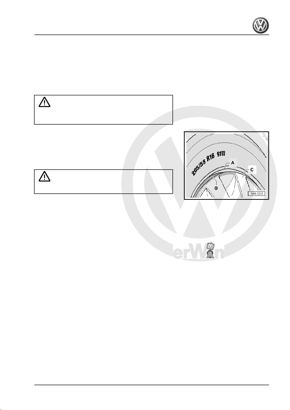
P
r
o
t
e
c
t
e
d
b
y
c
o
p
y
r
i
g
h
t
.
C
o
p
y
i
n
g
f
o
r
p
r
i
v
a
t
e
o
r
c
o
m
m
e
r
c
i
a
l
p
u
r
p
o
s
e
s
,
i
n
p
a
r
t
o
r
i
n
w
h
o
l
e
,
i
s
n
o
t
p
e
r
m
i
t
t
e
d
u
n
l
e
s
s
a
u
t
h
o
r
i
s
e
d
b
y
V
o
l
k
s
w
a
g
e
n
A
G
.
V
o
l
k
s
w
a
g
e
n
A
G
d
o
e
s
n
o
t
g
u
a
r
a
n
t
e
e
o
r
a
c
c
e
p
t
a
n
y
l
i
a
b
i
l
i
t
y
w
i
t
h
r
e
s
p
e
c
t
t
o
t
h
e
c
o
r
r
e
c
t
n
e
s
s
o
f
i
n
f
o
r
m
a
t
i
o
n
i
n
t
h
i
s
d
o
c
u
m
e
n
t
.
C
o
p
y
r
i
g
h
t
b
y
V
o
l
k
s
w
a
g
e
n
A
G
.
Amarok 2011 ➤ , Caddy 2004 ➤ , Caddy 2011 ➤ , Caddy Kasten/Kombi 1996 ➤ ...
Wheels and Tyres Guide - Edition 11.2012
• the tyres are more than 6 years old.
6.1.7 Tyres with flange protection
The tyre industry produces tyres with flange protection for alloy
wheels. The flange protection is intended to protect alloy wheels
from damage due to contact with kerbs.
The combination of tyres with flange protection, steel wheels and
a full-size hub cap can lead to the loss of the hub cap during op‐
eration. The flexing of the tyre separates the hub cap from its seat.
WARNING
When fitting tyres, always make sure that only tyres without
flange protection are fitted to steel rims.
The figure shows a prohibited combination of steel rim, full-size
hub cap and a tyre with flange protection.
A - Flange protection
B - Flange of a steel rim
C - Full size hub cap
This combination must never be fitted!
WARNING
6.1.8 Winter tyres
As of 01.05.2006, a change to the German road traffic regulations
(StVO) came into force which caused the following supplement
to be made: "The equipment in motor vehicles has to be adapted
to the weather conditions. In particular, this includes suitable tyres
and antifreeze in the windscreen washing system."
Please point out to customers that, since May 1st 2006, they are
legally obliged to adapt their vehicle's equipment, particularly the
tyres, to winter weather conditions.
For driving in winter, we recommend that the vehicle is equipped
with winter tyres in the sizes recommended in table 2 of the parts
certificates.
As a basic rule:
All tyre sizes listed in the vehicle documents can also be used as
winter tyres.
The handling characteristics may be affected by the use of winter
tyres and the possible change in the dimensions of the wheel and
tyre. Therefore, when using winter tyres, you must adapt your
speed to the changed handling characteristics and to the road
conditions.
To achieve the best possible handling, winter tyres must be fitted
on all wheels.
If the vehicle is equipped with rims other than the factory-fitted
rims, you must take the following into consideration when you fit
winter tyres:
♦ Wheels and wheel bolts are matched.
♦ Whenever the wheels are changed, corresponding wheel bolts
of the correct length and with the correctly shaped tapered
6. Facts about wheels and tyres (commercial vehicles) 21
P
r
o
t
e
c
t
e
d
b
y
c
o
p
y
r
i
g
h
t
.
C
o
p
y
i
n
g
f
o
r
p
r
i
v
a
t
e
o
r
c
o
m
m
e
r
c
i
a
l
p
u
r
p
o
s
e
s
,
i
n
p
a
r
t
o
r
i
n
w
h
o
l
e
,
i
s
n
o
t
p
e
r
m
i
t
t
e
d
u
n
l
e
s
s
a
u
t
h
o
r
i
s
e
d
b
y
V
o
l
k
s
w
a
g
e
n
A
G
.
V
o
l
k
s
w
a
g
e
n
A
G
d
o
e
s
n
o
t
g
u
a
r
a
n
t
e
e
o
r
a
c
c
e
p
t
a
n
y
l
i
a
b
i
l
i
t
y
w
i
t
h
r
e
s
p
e
c
t
t
o
t
h
e
c
o
r
r
e
c
t
n
e
s
s
o
f
i
n
f
o
r
m
a
t
i
o
n
i
n
t
h
i
s
d
o
c
u
m
e
n
t
.
C
o
p
y
r
i
g
h
t
b
y
V
o
l
k
s
w
a
g
e
n
A
G
.
Amarok 2011 ➤ , Caddy 2004 ➤ , Caddy 2011 ➤ , Caddy Kasten/Kombi 1996 ➤ ...
Wheels and Tyres Guide - Edition 11.2012
seats are used 1). The secure fit of the wheels and the func‐
tioning of the brakes depends this.
♦ The suitability of winter tyres with less than 4…5 mm tread
depth for winter operation is limited.
♦ Some countries require winter tyres to have a tread depth of
at least 4 mm.
♦ We recommend that winter tyres be replaced after no more
than six years. The special “winter properties” of these tyres
decline with age, regardless of how much they are used.
Tyre pressure for winter tyres
The tyre pressure for winter tyres must be 0.2 bar more than the
applicable tyre pressure for standard tyres but not more than
3.5 bar.
Registration regulations in the Federal Republic of Germany
Only when winter tyres are in use may the top speed that a vehicle
can achieve be greater than the maximum speed specified by the
speed symbol of the tyre.
In this case, a label stating the following must be attached:
Important! Winter tyres!
Maximum speed … km/h
Note
This label must be clearly visible to the driver!
1) A spherical cap is the curved surface of a section of a sphere cut by a plane.
The tapered seats on the wheel bolt and in the wheel (rim) in the wheel bolt holes
are spherical caps.
6.1.9 Reinforced and Extra Load (XL) tyres
Some tyre manufacturers have for some time replaced the des‐
ignation “Reinforced” with the designation “Extra Load”. This
designation has long been standard in non-European countries.
Technically, there is no difference between them.
Some tyre manufacturers also use the designation “XL” for Extra
Load tyres.
Tyres with the designation “Reinforced” or “Extra Load (XL)” are
of equal quality.
6.1.10 Snow chains
Snow chains may be fitted to driven wheels only.
On all-wheel drive vehicles, however, only the front wheels may
be fitted with snow chains (or the rear wheels on the Amarok).
It is not possible to use snow chains with all wheel and tyre com‐
binations. Notes on this can be found in the vehicle tables of the
parts certificate.
If no particular type of snow chain is specified, then small-link
chains may be used. These, including the chain fastener, may not
protrude more than 15 mm beyond the wheel's tread and the inner
wall.
On some models, only special, small-link chains are possible with
certain wheel and tyre combinations. Notes on this can be found
in the vehicle tables of the parts certificate.
22 Rep. gr.44 - Wheels, tyres, vehicle geometry
 Loading...