


Volkswagen Amarok User Manual
Service Training
Self-study programme 464
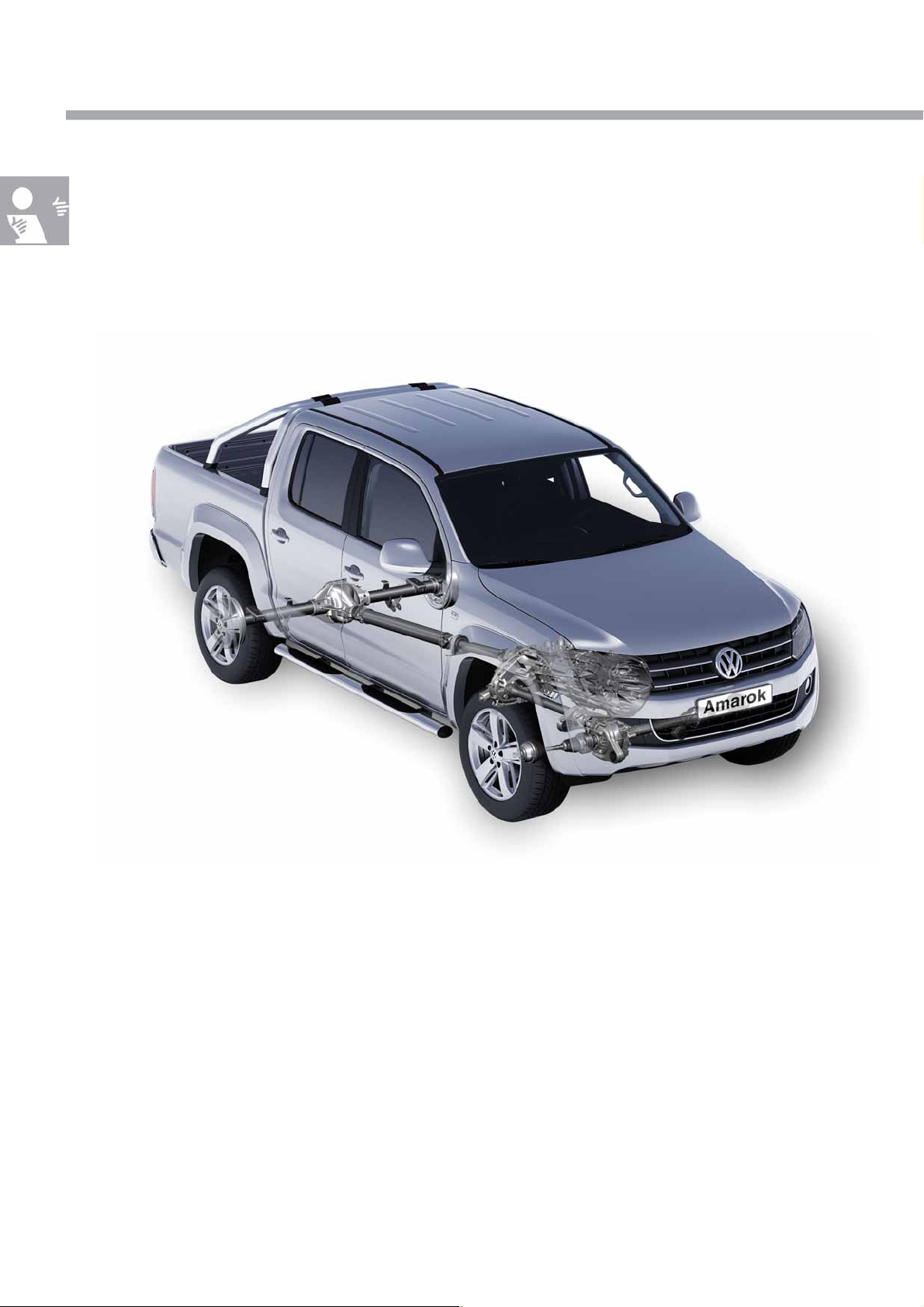
The Amarok Powertrain and drive concept
Design and function
Commercial
Ve h i c le s
S464_002
With the Amarok, Volkswagen Commercial Vehicles is deliberately and self-assuredly taking part in the global
trend towards multifunctional vehicle s.
As such, the company is making consistent use of its extensive experience in manufacturing vehicles with both rear
and front-wheel drive. The newly developed drive concept offers outstanding driving properties.
Comfortable handling and operation similar to a passenger car are features of the Amarok. Magnificent assistance
is given for everyday use through a range of support systems in order to provide road safety and handling benefits
when offroad.
In all cases and in all variants, the Amarok can be used both onroad and for heavy-duty offroad use. Depending
on use, the four-wheel drive version of the Amarok is available either with permanently or non-permanently
engaged four-wheel drive. The Amarok is also available in a standard version with rear-wheel drive. The entire
driveline of the Amarok is a new development and has been specifically adapted for use as a commercial vehicle.
Please also refer to self-study programme no. 463
"The Amarok".
The self-study programme presents the
design and function of
new developments!
The content will not be updated.
Current testing , setting an d repair instructions
can be found in the provided
service literature.
Important
note
2

At a glance
Introduction . . . . . . . . . . . . . . . . . . . . . . . . . . . . . . . . . . . . . . . . . . . . . . . . . . . . . 4
Four-wheel drive development at Volkswagen Commercial Vehicles . . . . . . . 4
The drive concept of the Amarok . . . . . . . . . . . . . . . . . . . . . . . . . . . . . . . . . . . . 6
The driveline . . . . . . . . . . . . . . . . . . . . . . . . . . . . . . . . . . . . . . . . . . . . . . . . . . . . . 8
Operation . . . . . . . . . . . . . . . . . . . . . . . . . . . . . . . . . . . . . . . . . . . . . . . . . . . . . 10
The operation . . . . . . . . . . . . . . . . . . . . . . . . . . . . . . . . . . . . . . . . . . . . . . . . . . . . 10
The offroad drive programme . . . . . . . . . . . . . . . . . . . . . . . . . . . . . . . . . . . . . . . 14
6-speed manual gearbox 0C6 . . . . . . . . . . . . . . . . . . . . . . . . . . . . . . . . . . . . 16
The 6-speed manual gearbox . . . . . . . . . . . . . . . . . . . . . . . . . . . . . . . . . . . . . . 16
The gearbox structure and function . . . . . . . . . . . . . . . . . . . . . . . . . . . . . . . . . 18
The gearbox sectional view . . . . . . . . . . . . . . . . . . . . . . . . . . . . . . . . . . . . . . . . 20
The powerflow . . . . . . . . . . . . . . . . . . . . . . . . . . . . . . . . . . . . . . . . . . . . . . . . . . . 26
The external selector mechanism . . . . . . . . . . . . . . . . . . . . . . . . . . . . . . . . . . . 28
The internal selector mechanism . . . . . . . . . . . . . . . . . . . . . . . . . . . . . . . . . . . . 30
Transfer box . . . . . . . . . . . . . . . . . . . . . . . . . . . . . . . . . . . . . . . . . . . . . . . . . . . 32
The non-permanently engaged four-wheel drive with transfer box 0C7 . . . 32
The transfer box with limited-slip interaxle differential 0BU . . . . . . . . . . . . . . 46
Rear final drive 0CC . . . . . . . . . . . . . . . . . . . . . . . . . . . . . . . . . . . . . . . . . . . . . 48
The rear final drive 0CC . . . . . . . . . . . . . . . . . . . . . . . . . . . . . . . . . . . . . . . . . . . 48
Front final drive 0C1 . . . . . . . . . . . . . . . . . . . . . . . . . . . . . . . . . . . . . . . . . . . . . 55
The front final drive 0C1 . . . . . . . . . . . . . . . . . . . . . . . . . . . . . . . . . . . . . . . . . . . 55
Test your knowledge . . . . . . . . . . . . . . . . . . . . . . . . . . . . . . . . . . . . . . . . . . . . 58
3
Introduction
Four-wheel drive development at
Volkswagen Commercial Vehicles
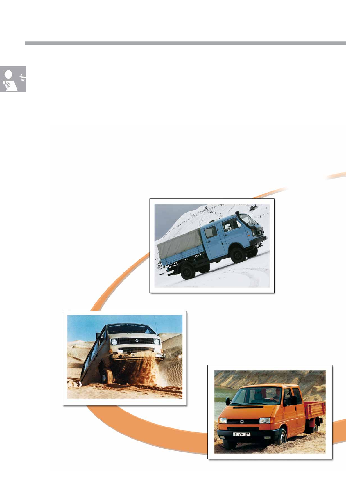
Volkswagen Commercial Vehicles began to manufacture four-wheel drive vehicles in-house in 1983
in the form of the LT1 4x4.
This was an early response to the desire for as wide a range of vehicle applications as possible – from driving on
smooth roads through to use on very difficult ground.
The four-wheel drive is better able to overcome traction problems when used in sports applications and, in
particular, as a commercial vehicle.
LT1 4x 4
from 1983
T3 syncro
from 1985
T4 syncro
from 1993
4
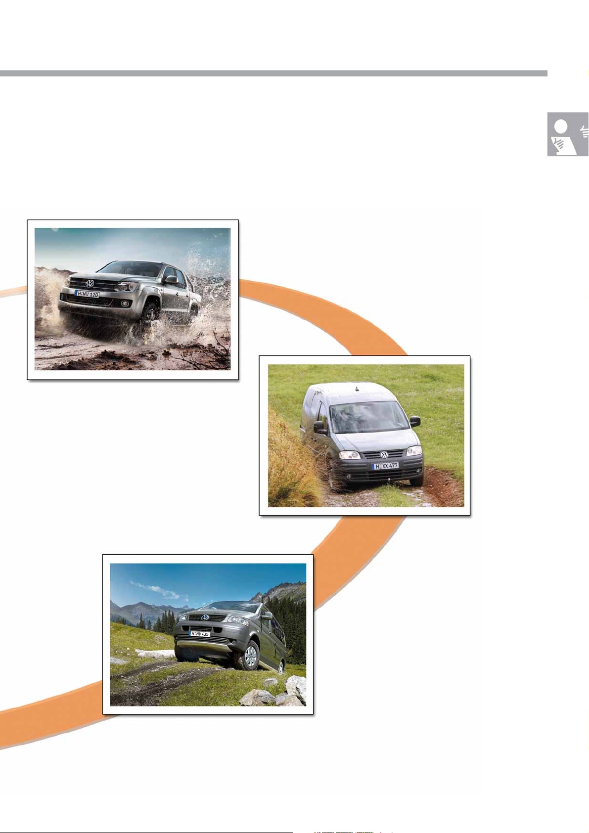
Volkswagen Commercial Vehicles markets vehicles all over the world, therefore the company is used to taking
account of special conditions, such as in remote areas and difficult open ground – four-wheel drive represents an
ideal solution for this.
Amarok 4MOTION
from 2010
Caddy 4MOTION
from 2009
T5 4MOTION
from 2004
S464_051
5
Introduction
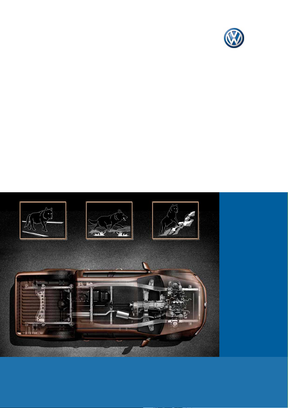
The drive concept of the Amarok
The drive concept of the Amarok offers 3 different drive variants.
The Amarok's powertrain is efficiently supported by intelligent vehicle dynamics programmes.
S464_058
Vehicle dynamics programmes
The Amarok is equipped with the following vehicle dynamics programmes:
● ABS (as standard)
● TCS (as standard)
MSR (as standard)
EDL (as standard)
● ESP
6
● Offroad drive programme (as standard)
● Hill-descent assist
● Hill-hold assist
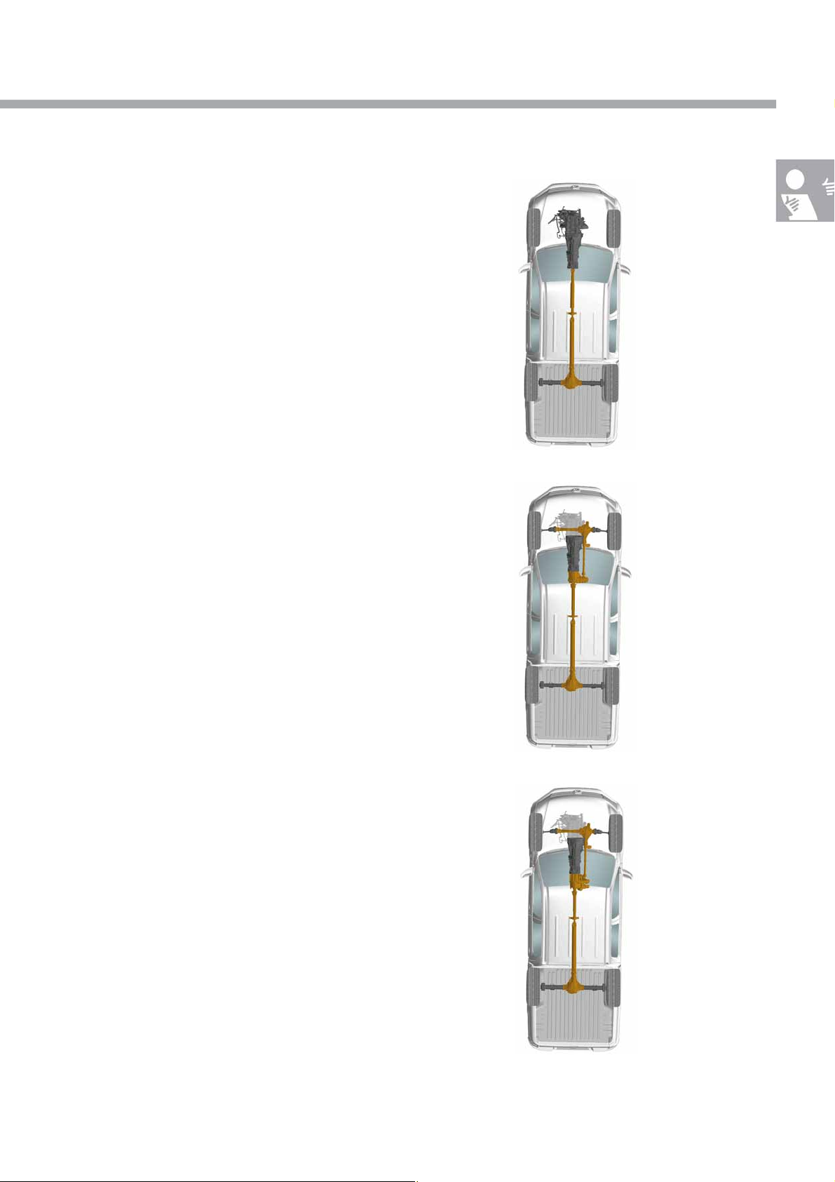
Rear final drive
In the Amarok with rear-wheel drive, the power is
transmitted via a propshaft to the rear axle only.
Even with only rear-wheel drive, the Amarok can be
used on both consolidated and non-consolidated
roads as well as offroad.
Permanent four-wheel drive
with limited-slip interaxle
differential 0BU
In the Amarok with permanently engaged four-wheel
drive, the powerflow to both driven axles is distributed
by means of a transfer box with permanent
engagement using a limited-slip interaxle differential.
This offers improved traction compared to rear-wheel
drive, above all when offroad.
S464_006
Non-permanently engaged
four-wheel drive with part-time
transfer box 0C7
In the Amarok with non-permanently engaged fourwheel drive, the powerflow to the driven axle is
distributed using a transfer box with electrically
engaged front final drive. It is also possible to engage
a reduction stage (offroad ratio) in this transfer box.
In this version, the Amarok is even better suited for
use on difficult ground.
S464_074
S464_005
7
Introduction
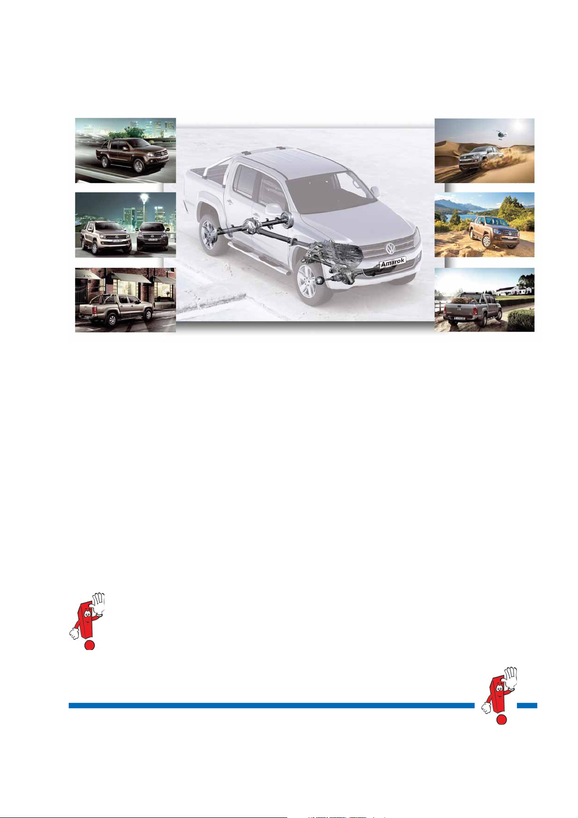
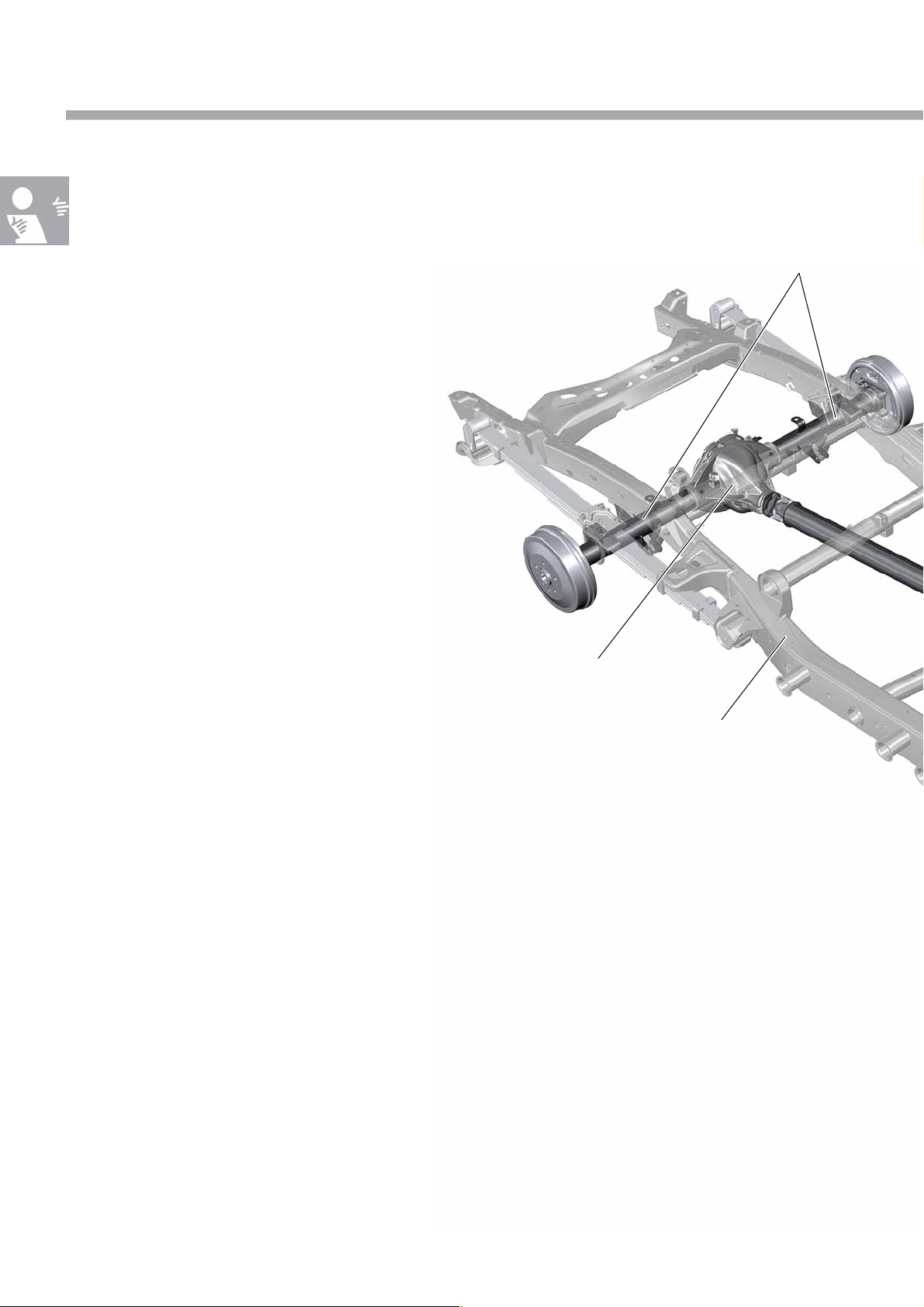
The driveline
The Amarok has a modular driveline in which the individual
components such as manual gearbox, front final drive, transfer
box and rear final drive are independent subassemblies.
Gearbox
At present, the 6-speed manual gearbox 0C6 is used
for transmitting power from the engine
Rear axle
Transfer box
Power is distributed to the final drives either by means
of the transfer box 0C7 (non-permanently engaged
four-wheel drive) or 0BU (permanently engaged
four-wheel drive).
Rear final drive
Lad der f ram e
Propshafts
Three different two-part propshafts are used for driving the rear axle.
The front part of the propshaft has a length that is adapted to the particular drive version.
A one-piece propshaft is fitted for driving the front axle. This is identical in both versions of the four-wheel drive.
8
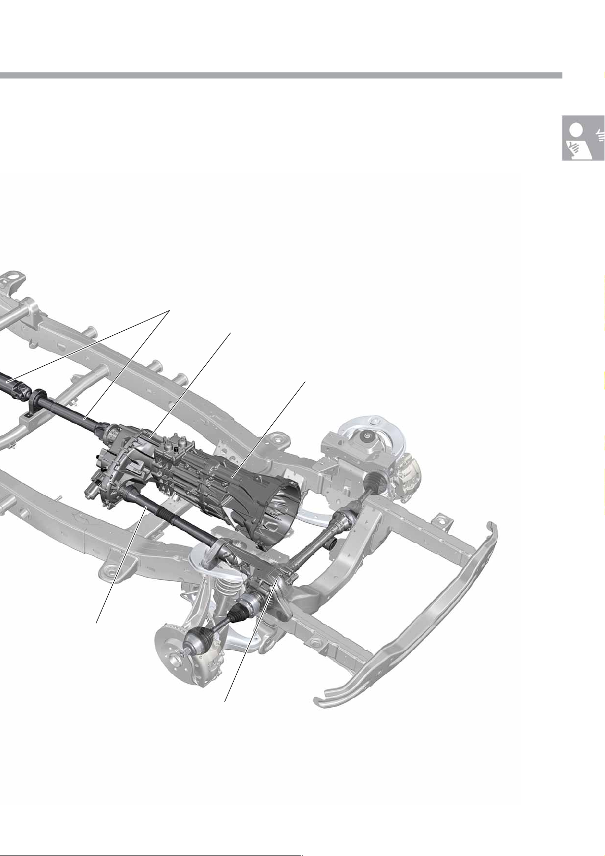
Rear final drive, front final drive
The rear final drive 0CC arranged in a symmetrical installation position is used for driving the rear axle. The rear
axle differential can be locked up.
The front final drive 0C1 is used for driving the front axle, and is available in two different designs. The front final
drive is asymmetrically arranged.
Rear propshaft
Transfer box
6-speed manual gearbox
Front propshaft
Front final drive
The illustration shows the drivetrain with non-permanently engaged four-wheel drive.
S464_007
9
Operation
The operation
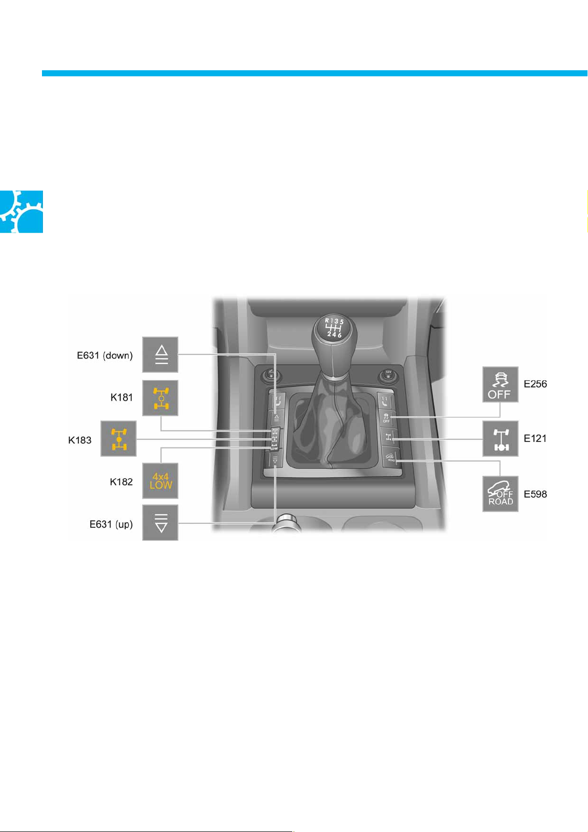
Four-wheel drive, the reduction ratio (offroad ratio), the differential lock and the offroad drive programme are
engaged and disengaged using a button panel in the centre console. The status is displayed by warning lamps
K181, K182 and K183.
The four-wheel drive components are each electrically connected to the gearbox.
This means no additional selector levers are required for operating the four-wheel drive ranges.
Centre console button assignments
10
Key
E631 (down) = Running gear programme switch
(switching on)
K181 Normal operation warning lamp in transfer box
operating unit (4x2)
K183 Longitudinal lock-up warning lamp in transfer
box operating unit (4x4 HIGH)
K182 Reduction gearing warning lamp in transfer box
operating unit
(4x4 LOW)
E631 (up) = Running gear programme switch
(switching off)
S464_049
E256 TCS and ESP button (TCS deactivation)
E121 Rear differential lock switch
E598 Driving programme button (offroad driving
programme)
E256, E121 and E598 do not have function
lighting
In right-hand drive vehicles, button panel E631 is fitted
on the other side of the selector lever.
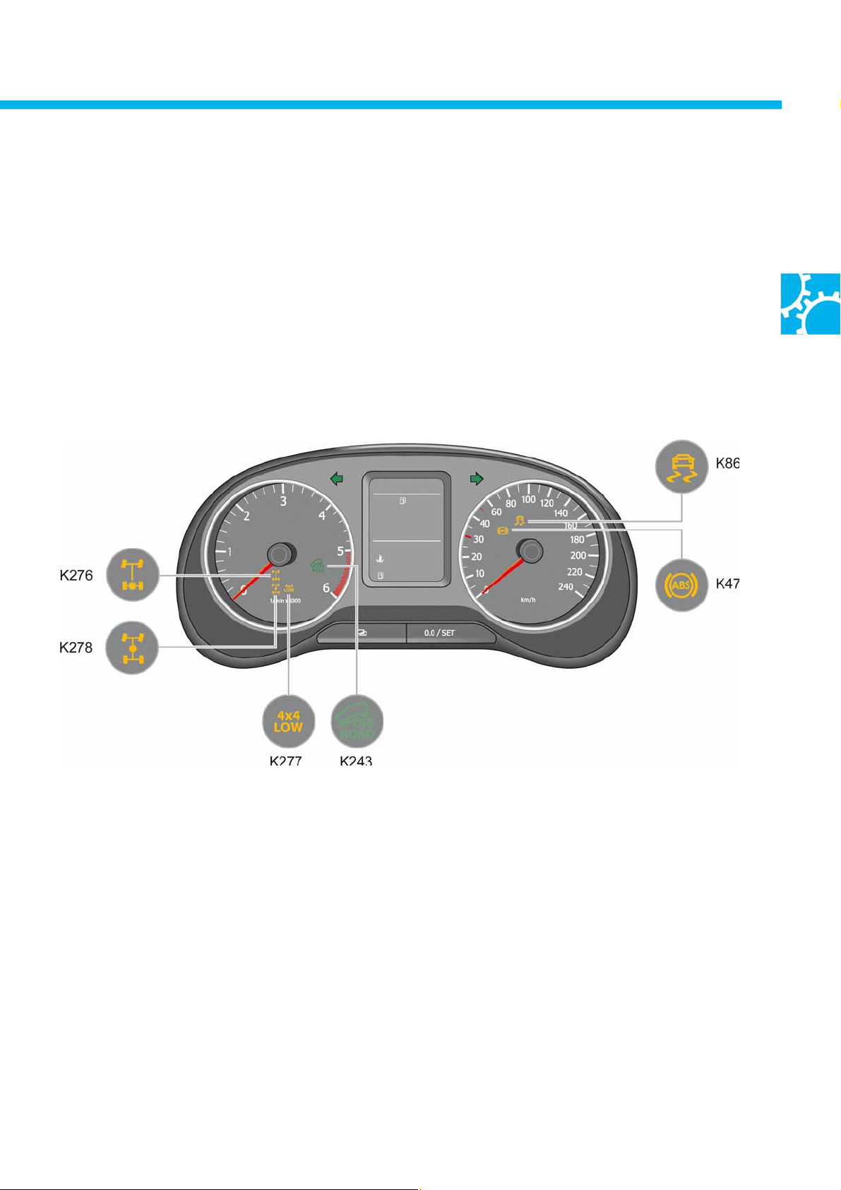
Displays on the dash panel insert
Each of the four-wheel drive statuses that are activated during operation is backlit in the button panel and also
shown in the dash panel insert as a status display.
The status of 4x2 rear-axle mode is only displayed in the centre console.
Key
K278 Longitudinal lock-up warning lamp (4x4 HIGH)
K277 Warning lamp for gearbox low range
K276 Warning lamp for rear transverse lock
K47 ABS warning lamp (ABS fault or ABS deactivated)
K86 Traction control system warning lamp (fault, control or deactivated)
K243 Driving programme warning light (offroad driving programme)
S464_050
11

Operation
Four-wheel drive 4x4 HIGH
Display in the dash panel insert
… four-wheel drive is engaged
(interaxle lock engaged)
S464_077
Switch-on conditions
● Ter m in al 1 5 " ON "
● E631 (up) pressed > 0.5 s
● Can be engaged at any vehicle speed
● No undervoltage
● No relevant error memory entry
Offroad range 4x4 LOW
Display in the dash panel insert
Switch-off conditions
● Ter m i n al 15 " O N"
● E631 (down) pressed > 0.5 s
● Can be switched off at any vehicle speed
● No undervoltage
● No relevant error memory entry
… four-wheel drive is engaged and LOW
reduction ratio engaged
12
S464_079
Switch-on conditions
● Engine speed < 1500 rpm
● E631 (up) pressed > 0.5 s
● Vehicle speed v < 1 km/h
● 4x4 HIGH engaged
● No undervoltage
● No relevant error memory entry
Switch-off conditions
● Engine speed < 1500 rpm
● E631 (down) pressed > 0.5 s
● Vehicle speed v < 1 km/h
● No undervoltage
● No relevant error memory entry

Differential lock
Display in the dash panel insert
… differential lock engaged
S464_081
Switch-on conditions
● Engine running
● E121 pressed > 0.5 s
● Can be engaged at any vehicle speed
● No undervoltage
● No relevant error memory entry
● With non-permanently engaged four-wheel drive:
Four-wheel drive range 4x4 LOW engaged
Switch-off conditions
● Button pressed > 0.5 s (E121)
● Can be switched off at any vehicle speed
● 30 s follow-on operation after tl. 15 "OFF".
If the engine stalls whilst driving with the
differential lock engaged, the lock remains
engaged for a period of 30 seconds after tl. 15
"OFF". This means restarting and moving off are
possible with the lock engaged. As a result , driving
comfort is increased when driving offroad.
The following applies to all variants 4x4 HIGH, 4x4 LOW and for the differential lock with regard to operation
The driver's request for engaging the required four-wheel drive range is stored for 10 s. If the required activation
conditions are met within this period then the four-wheel drive ranges 4x4 HIGH, 4x4 LOW and the differential lock
are engaged. Operating comfort is therefore improved.
ABS/ESP system statuses
ABS/ESP control is retained during four-wheel drive operation (4x4 HIGH and 4x4 LOW) in all equipment variants of
the Amarok. In vehicles with non-permanently engaged four-wheel drive, ABS/ESP control is deactivated when the
differential lock is engaged. The mechanical link-up between the two axles (4x4 HIGH /4x4 LOW) and the additional
link-up between the two rear wheels means that individual ABS/ESP control for individual wheels is no longer
possible. Deactivation is displayed by warning lamps K86 and K47 in the dash panel insert. In vehicles with
permanently engaged four-wheel drive, the ABS/ESP function is also retained when the differential lock is engaged.
13

Operation
The offroad drive programme
The offroad drive programme is used as standard in all vehicle variants of the Amarok.
It is intended to assist the driver in special driving situations when offroad. The possible extended functions of the
ABS/ESP control unit are used in this case.
● Offroad ABS (adaptations in the ABS control behaviour)
● Offroad ESP (adaptations in the ABS and ESP control behaviour)
● Hill-descent assist
Activation of the offroad programme and indication
The offroad programme is activated
● Manually – by pressing the driving programme button E598
(in the centre console, on the right of the selector lever) or
● Automatically – when 4x4 LOW drive range is activated
Display showing activation of the offroad drive programme
Activation of the offroad drive programme is indicated by the driving
programme warning light K243 in the dash panel insert.
Configurations
● Vehicles with ABS (MK25 E) have offroad ABS
● Vehicles with ESP (MK25 XT) have offroad ABS/ESP
and hill descent control
Activation conditions for the offroad
programme
The offroad drive programme remains active
● Ter m i na l 15 " O N "
● E598 pressed > 0.5 s
Special case in vehicles with non-permanently
engaged four-wheel drive
When 4x4 LOW drive range is engaged, the offroad
programme is activated automatically.
following activation until the next change of ignition
status, without interruption.
For example, if the engine is stalled when driving
offroad, the offroad drive programme also remains
activated after restarting, with a follow-on operation
of 30 s after a change of status on tl. 15.
This increases driving comfort.
E598
S464_073
S464_072
14
Features of the offroad drive programme
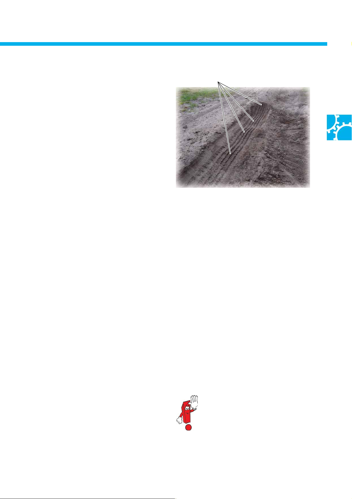
Offroad ABS
Vehicles with offroad ABS can brake better on
unconsolidated ground such as sand and gravel.
In ABS control, the pressure buildup and pressure
holding phases are extended. The depressurisation is
shorter and takes place later. This means wheel slip
can occur in each control phase, thereby building up
a skid wedge of loose material in front of the wheels.
The skid wedge brakes the vehicle additionally and
shortens the braking distance depending on the
composition of the ground.
Offroad ESP
Skid wedge
S464_076
Special information about using offroad ABS can be
found in the owner's manual .
Vehicles with ESP have adapted ESP control behaviour
as well as offroad ABS in order to improve traction:
● ESP intervenes somewhat later at speeds below
50 km/h when the vehicle is understeering.
● ESP intervenes somewhat later at speeds below
70 km/h when the vehicle is oversteering.
● ASR intervenes somewhat later at speeds below
70 km/h.
Hill-descent assist
The hill-descent assist makes descending steep hills more straightforward and more controllable. It limits the speed
by active brake intervention at all 4 wheel brakes using the ESP hydraulics. It keeps the speed constant after the
vehicle has started its descent. The driver can increase or reduce the speed at any time using the accelerator and
brakes. The hill-descent assist adjusts speed within its control range between 2 and max. 30 km/h. The system
functions when driving forwards and in reverse.
Switch-on conditions for hill-descent assist
● E598 pressed > 0.5 s
● Special feature with non-permanently engaged
four-wheel drive: automatic activation in 4x4 LOW
● Engine running
● Slope forwards > 10 %, reverse > 8 %
● Vehicle speed v < 30 km/h (> 30 km/h change to
standby mode)
● Driver brakes less than the downslope force
● Accelerator pedal is not pressed
For more information about the basic
function of the hill-descent assist, refer
to self-study programme 374
"Slip control and assistance systems".
15
6-speed manual gearbox 0C6
The 6-speed manual gearbox
A modern, fully synchronised 2-shaft gearbox of conventional design is used for transmitting power. It has a robust
structure and is designed for the specific requirements of commercial vehicles. The developer and manufacturer of
the 0C6 gearbox is ZF-Getriebe GmbH
● The 6-speed manual gearbox has a uniform housing for all drive variants.
● The same gear ratios are used for all engines.
● The newly-developed 6-speed manual gearbox is exclusively used in the Amarok at present.
S464_052
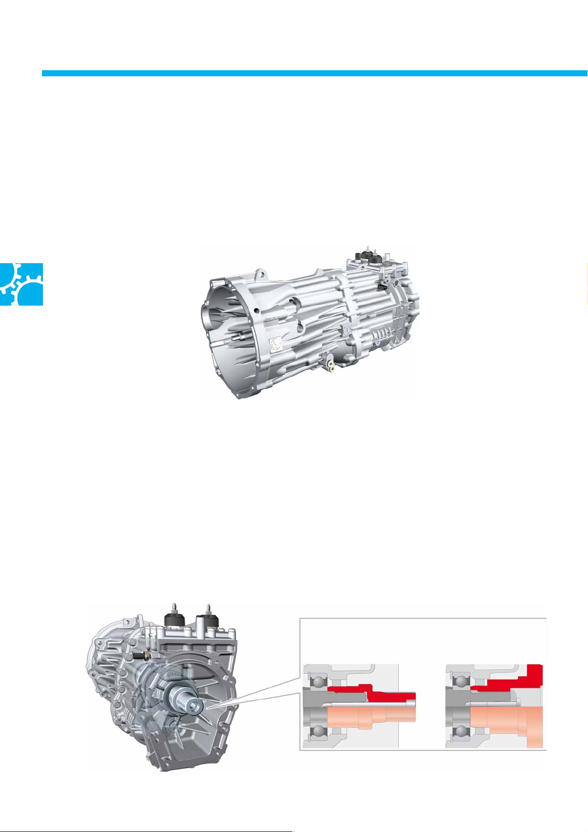
Gearbox – output adapter
There are two different gearbox variants for the two drive variants of rear-wheel drive and four-wheel drive. These
only differ in the area of the connection to the propshaft in vehicles with rear-wheel drive or the transfer box in
four-wheel drive vehicles.
Four-wheel drive – The torque is transferred from the manual gearbox to the transfer box via an adapter shaft.
The adapter shaft is connected to the gearbox output shaft by means of splines with a light press-fit seat , and is
additionally bolted.
Rear-wheel drive – The torque is transmitted onto the propshaft to the rear axle by means of an output flange. The
output flange is mounted on the splines of the output shaft by means of a light press-fit seat, and is additionally
secured by a bolted connection.
Adapter shaft for
four-wheel drive
Output flange for
rear-wheel drive
Picture corresponds
to adapter shaft for
four-wheel drive
16
S464_062
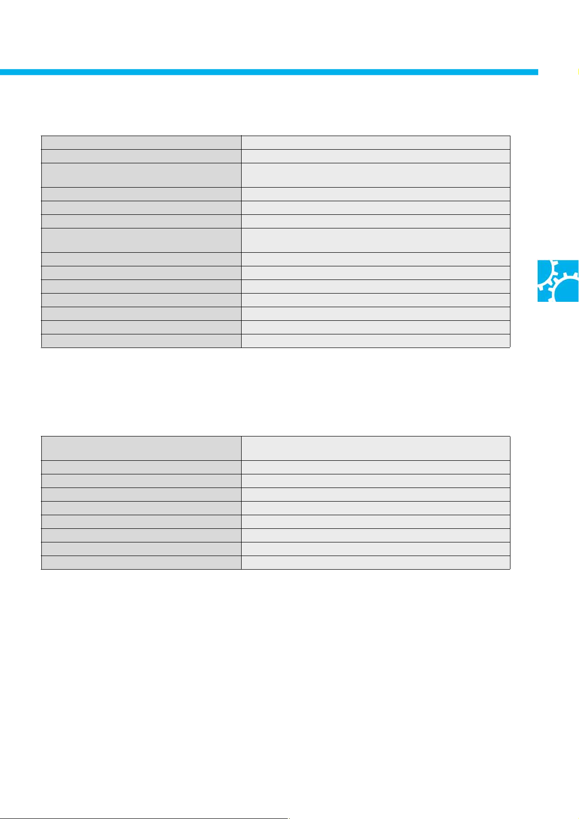
Techn ic al d ata
Gearbox designation 0C6
Gearbox type 6-speed manual gearbox
Gearbox code e.g. MQU (4x2) NFG, NCR
MQV, MJE (4x4) NFF, NCQ, MJE
max. transmissible torque 400 Nm
Shafts Input shaft and coaxial output shaft, layshaft, R-gear reverse shaft
Installation location Longitudinal installation
Use with the engines … 90/120kW TDI engines
118kW TSI engine
Shaft clearance 85 mm
Structural length 690 mm
Weigh t 61 kg
Gear oil specification Synthetic gear oil (SAE 75W-80)
Fill quantity of lifetime fill First fill: 1.5 l, change volume: 1.4 l
Change interval Lifetime fill
Clutch mechanism Hydraulic
Ratios
Gear ratio
1st gear 4.82
2nd gear 2.54
3rd gear 1.49
4th gear 1.0
5th gear 0.76
6th g ear 0.64
Reverse gear 4.37
Spread 7.5 3
The gear ratios in all gearbox variants are the same. 5th and 6th gears are configured as overdrive.
The vehicle's maximum speed is reached in 5th gear and also in 6th gear. 6th gear is an override used for saving
fuel, since the engine rpm is significantly lower.
This reduces CO2 emissions and reduces wear in the engine.
Example: 120kW TDI engine (calculated values)
– Vmax 5th gear = 179.5 km/h at 4135 rpm
– Vmax 6th gear = 178.9 km/h at 3457 rpm
1st gear has a relatively high mechanical advantage, specifically for a commercial vehicle. This is used for moving
off without overloading the clutch when the vehicles are heavily loaded and/or towing a trailer.
17
6-speed manual gearbox 0C6
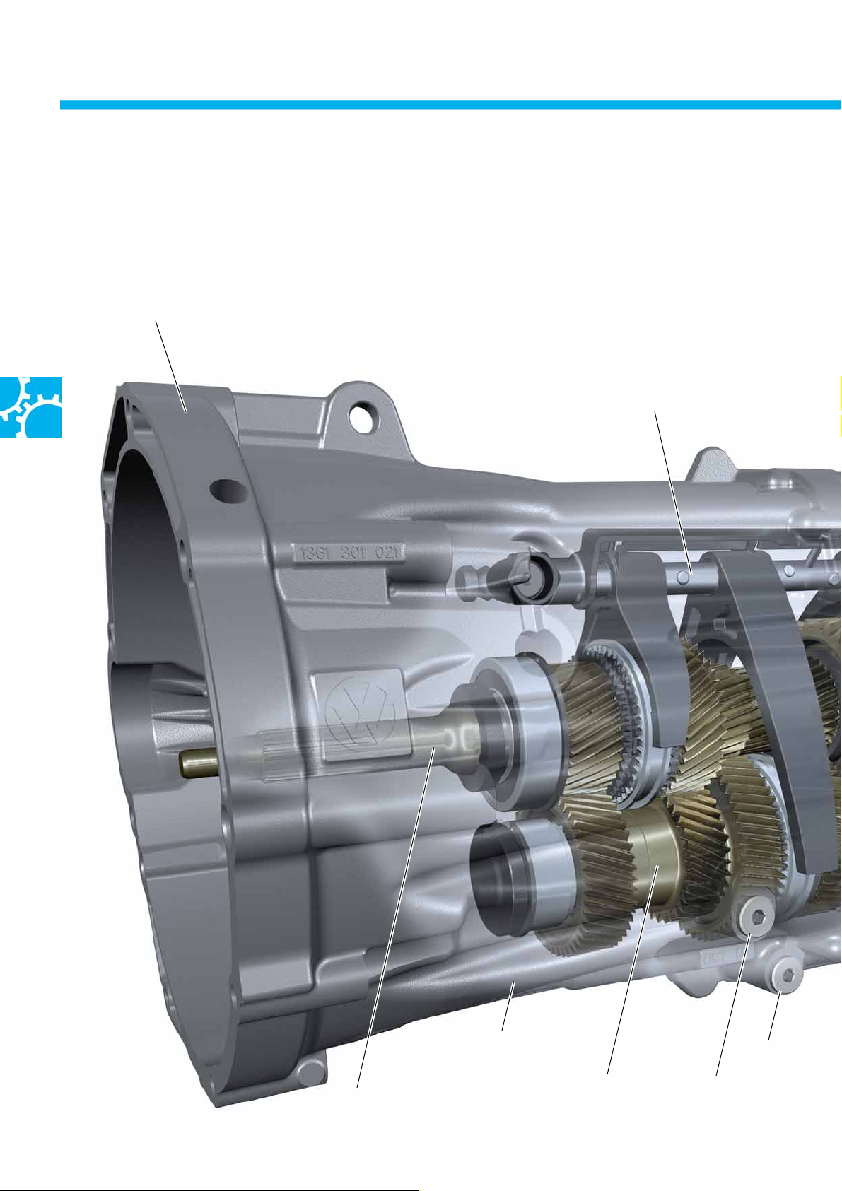
The gearbox structure and function
The two-part gearbox housing is made from aluminium diecastings.
Housing flange
for connection to the engine
Centre selector shaft
18
Input shaft
Front gearbox housing
Laysha ft
Oil drain plug
Oil filler plug
 Loading...