


Volkswagen Golf Variant 2010 User Manual

P
r
o
t
e
c
t
e
d
b
y
c
o
p
y
r
i
g
h
t
.
C
o
p
y
i
n
g
f
o
r
p
r
i
v
a
t
e
o
r
c
o
m
m
e
r
c
i
a
l
p
u
r
p
o
s
e
s
,
i
n
p
a
r
t
o
r
i
n
w
h
o
l
e
,
i
s
n
o
t
p
e
r
m
i
t
t
e
d
u
n
l
e
s
s
a
u
t
h
o
r
i
s
e
d
b
y
V
o
l
k
s
w
a
g
e
n
A
G
.
V
o
l
k
s
w
a
g
e
n
A
G
d
o
e
s
n
o
t
g
u
a
r
a
n
t
e
e
o
r
a
c
c
e
p
t
a
n
y
l
i
a
b
i
l
i
t
y
w
i
t
h
r
e
s
p
e
c
t
t
o
t
h
e
c
o
r
r
e
c
t
n
e
s
s
o
f
i
n
f
o
r
m
a
t
i
o
n
i
n
t
h
i
s
d
o
c
u
m
e
n
t
.
C
o
p
y
r
i
g
h
t
b
y
V
o
l
k
s
w
a
g
e
n
A
G
.
Service
Workshop Manual
Golf Variant 2007 ➤
Golf Variant 2010 ➤
Jetta 2005 ➤
Jetta 2011 ➤
6-speed automatic gearbox 09G
Edition 04.2010
Service Department. Technical Information

P
r
o
t
e
c
t
e
d
b
y
c
o
p
y
r
i
g
h
t
.
C
o
p
y
i
n
g
f
o
r
p
r
i
v
a
t
e
o
r
c
o
m
m
e
r
c
i
a
l
p
u
r
p
o
s
e
s
,
i
n
p
a
r
t
o
r
i
n
w
h
o
l
e
,
i
s
n
o
t
p
e
r
m
i
t
t
e
d
u
n
l
e
s
s
a
u
t
h
o
r
i
s
e
d
b
y
V
o
l
k
s
w
a
g
e
n
A
G
.
V
o
l
k
s
w
a
g
e
n
A
G
d
o
e
s
n
o
t
g
u
a
r
a
n
t
e
e
o
r
a
c
c
e
p
t
a
n
y
l
i
a
b
i
l
i
t
y
w
i
t
h
r
e
s
p
e
c
t
t
o
t
h
e
c
o
r
r
e
c
t
n
e
s
s
o
f
i
n
f
o
r
m
a
t
i
o
n
i
n
t
h
i
s
d
o
c
u
m
e
n
t
.
C
o
p
y
r
i
g
h
t
b
y
V
o
l
k
s
w
a
g
e
n
A
G
.
List of Workshop Manual Repair GroupsList of Workshop Manual
Repair GroupsList of Workshop Manual Repair Groups
Re pa ir G ro up
00 - Technical data
32 - Torque converter
37 - Controls, housing
38 - Gears, control
39 - Final drive - differential
Service
Technical information should always be available to the foremen and mechanics, because their
careful and constant adherence to the instructions is essential to ensure vehicle road-worthiness and
safety. In addition, the normal basic safety precautions for working on motor vehicles must, as a
matter of course, be observed.
All rights reserved.
No reproduction without prior agreement from publisher.
Copyright © 2010 Volkswagen AG, Wolfsburg MEX5R005320

P
r
o
t
e
c
t
e
d
b
y
c
o
p
y
r
i
g
h
t
.
C
o
p
y
i
n
g
f
o
r
p
r
i
v
a
t
e
o
r
c
o
m
m
e
r
c
i
a
l
p
u
r
p
o
s
e
s
,
i
n
p
a
r
t
o
r
i
n
w
h
o
l
e
,
i
s
n
o
t
p
e
r
m
i
t
t
e
d
u
n
l
e
s
s
a
u
t
h
o
r
i
s
e
d
b
y
V
o
l
k
s
w
a
g
e
n
A
G
.
V
o
l
k
s
w
a
g
e
n
A
G
d
o
e
s
n
o
t
g
u
a
r
a
n
t
e
e
o
r
a
c
c
e
p
t
a
n
y
l
i
a
b
i
l
i
t
y
w
i
t
h
r
e
s
p
e
c
t
t
o
t
h
e
c
o
r
r
e
c
t
n
e
s
s
o
f
i
n
f
o
r
m
a
t
i
o
n
i
n
t
h
i
s
d
o
c
u
m
e
n
t
.
C
o
p
y
r
i
g
h
t
b
y
V
o
l
k
s
w
a
g
e
n
A
G
.
Golf Variant 2007 ➤ , Golf Variant 2010 ➤ , Jetta 2005 ➤ , Jetta 2011 ➤
6-speed automatic gearbox 09G - Edition 04.2010
Contents
00 - Technical data . . . . . . . . . . . . . . . . . . . . . . . . . . . . . . . . . . . . . . . . . . . . . . . . . . . . 1
1 Suggestions and criticism, general repair notes . . . . . . . . . . . . . . . . . . . . . . . . . . . . . . . . . . 1
1.1 Suggestions and criticism of this workshop manual . . . . . . . . . . . . . . . . . . . . . . . . . . . . . . 1
1.2 General repair notes . . . . . . . . . . . . . . . . . . . . . . . . . . . . . . . . . . . . . . . . . . . . . . . . . . . . . . 2
1.3 Gearbox . . . . . . . . . . . . . . . . . . . . . . . . . . . . . . . . . . . . . . . . . . . . . . . . . . . . . . . . . . . . . . . . 2
1.4 Torque converter . . . . . . . . . . . . . . . . . . . . . . . . . . . . . . . . . . . . . . . . . . . . . . . . . . . . . . . . 2
1.5 ATF . . . . . . . . . . . . . . . . . . . . . . . . . . . . . . . . . . . . . . . . . . . . . . . . . . . . . . . . . . . . . . . . . . . . 2
1.6 Automatic gearbox control unit J217 with fuzzy logic . . . . . . . . . . . . . . . . . . . . . . . . . . . . 2
1.7 Control units in vehicle . . . . . . . . . . . . . . . . . . . . . . . . . . . . . . . . . . . . . . . . . . . . . . . . . . . . 2
1.8 Information on “09G gearbox” . . . . . . . . . . . . . . . . . . . . . . . . . . . . . . . . . . . . . . . . . . . . . . 2
1.9 Tools . . . . . . . . . . . . . . . . . . . . . . . . . . . . . . . . . . . . . . . . . . . . . . . . . . . . . . . . . . . . . . . . . . 2
1.10 Gearbox . . . . . . . . . . . . . . . . . . . . . . . . . . . . . . . . . . . . . . . . . . . . . . . . . . . . . . . . . . . . . . . . 3
1.11 Gaskets, seals and oil . . . . . . . . . . . . . . . . . . . . . . . . . . . . . . . . . . . . . . . . . . . . . . . . . . . . 4
1.12 Nuts and bolts . . . . . . . . . . . . . . . . . . . . . . . . . . . . . . . . . . . . . . . . . . . . . . . . . . . . . . . . . . 4
1.13 Electrical components . . . . . . . . . . . . . . . . . . . . . . . . . . . . . . . . . . . . . . . . . . . . . . . . . . . . 4
1.14 Guided fault finding, vehicle self-diagnosis and testing . . . . . . . . . . . . . . . . . . . . . . . . . . . . 5
2 Gearbox identification . . . . . . . . . . . . . . . . . . . . . . . . . . . . . . . . . . . . . . . . . . . . . . . . . . . . . . 6
2.1 Gearbox codes . . . . . . . . . . . . . . . . . . . . . . . . . . . . . . . . . . . . . . . . . . . . . . . . . . . . . . . . . . 6
3 Capacities . . . . . . . . . . . . . . . . . . . . . . . . . . . . . . . . . . . . . . . . . . . . . . . . . . . . . . . . . . . . . . 7
3.1 Planetary gearbox and final drive . . . . . . . . . . . . . . . . . . . . . . . . . . . . . . . . . . . . . . . . . . . . 7
4 Codes, gearbox allocation, ratios ▸ . . . . . . . . . . . . . . . . . . . . . . . . . . . . . . . . . . . . . . . . . . 8
32 - Torque converter . . . . . . . . . . . . . . . . . . . . . . . . . . . . . . . . . . . . . . . . . . . . . . . . . . 9
1 Torque converter . . . . . . . . . . . . . . . . . . . . . . . . . . . . . . . . . . . . . . . . . . . . . . . . . . . . . . . . 9
1.1 Identification of torque converter . . . . . . . . . . . . . . . . . . . . . . . . . . . . . . . . . . . . . . . . . . . . 9
1.2 Draining torque converter . . . . . . . . . . . . . . . . . . . . . . . . . . . . . . . . . . . . . . . . . . . . . . . . . . 9
1.3 Removing and installing torque converter oil seal . . . . . . . . . . . . . . . . . . . . . . . . . . . . . . . . 9
1.4 Installing torque converter . . . . . . . . . . . . . . . . . . . . . . . . . . . . . . . . . . . . . . . . . . . . . . . . . . 10
37 - Controls, housing . . . . . . . . . . . . . . . . . . . . . . . . . . . . . . . . . . . . . . . . . . . . . . . . . . 11
1 Connecting “tester” . . . . . . . . . . . . . . . . . . . . . . . . . . . . . . . . . . . . . . . . . . . . . . . . . . . . . . 11
1.1 Connecting vehicle diagnosis, testing and information system VAS 5051 . . . . . . . . . . . . 11
2 Electrical and electronic components and their locations . . . . . . . . . . . . . . . . . . . . . . . . . . 13
3 Multifunction switch F125 . . . . . . . . . . . . . . . . . . . . . . . . . . . . . . . . . . . . . . . . . . . . . . . . . . 18
3.1 Removing multifunction switch F125 . . . . . . . . . . . . . . . . . . . . . . . . . . . . . . . . . . . . . . . . . . 18
3.2 Installing multifunction switch F125 . . . . . . . . . . . . . . . . . . . . . . . . . . . . . . . . . . . . . . . . . . 19
3.3 Adjusting multifunction switch F125 . . . . . . . . . . . . . . . . . . . . . . . . . . . . . . . . . . . . . . . . . . 20
4 Selector mechanism up to 02.2009 . . . . . . . . . . . . . . . . . . . . . . . . . . . . . . . . . . . . . . . . . . 22
4.1 Overview of selector mechanism up to 02.2009 . . . . . . . . . . . . . . . . . . . . . . . . . . . . . . . . 22
4.2 Removing and installing selector mechanism with selector lever up to 02.2009 . . . . . . . . 23
4.3 Removing and installing selector lever cable up to 02.2009 . . . . . . . . . . . . . . . . . . . . . . . . 23
4.4 Checking selector lever cable . . . . . . . . . . . . . . . . . . . . . . . . . . . . . . . . . . . . . . . . . . . . . . 30
4.5 Adjusting selector lever cable . . . . . . . . . . . . . . . . . . . . . . . . . . . . . . . . . . . . . . . . . . . . . . . . 30
4.6 Emergency release of selector lever . . . . . . . . . . . . . . . . . . . . . . . . . . . . . . . . . . . . . . . . . . 31
4.7 Removing and installing knob . . . . . . . . . . . . . . . . . . . . . . . . . . . . . . . . . . . . . . . . . . . . . . 32
4.8 Checking selector mechanism . . . . . . . . . . . . . . . . . . . . . . . . . . . . . . . . . . . . . . . . . . . . . . 33
5 Selector mechanism from 03.2009 onwards . . . . . . . . . . . . . . . . . . . . . . . . . . . . . . . . . . . . 35
5.1 Overview of selector mechanism in vehicles from 03.2009 onwards . . . . . . . . . . . . . . . . . . 35
5.2 Removing and installing selector lever and selector mechanism with selector lever cable from
03.2009 onwards . . . . . . . . . . . . . . . . . . . . . . . . . . . . . . . . . . . . . . . . . . . . . . . . . . . . . . . . 36
5.3 Emergency release of selector lever . . . . . . . . . . . . . . . . . . . . . . . . . . . . . . . . . . . . . . . . . . 37
Contents i

P
r
o
t
e
c
t
e
d
b
y
c
o
p
y
r
i
g
h
t
.
C
o
p
y
i
n
g
f
o
r
p
r
i
v
a
t
e
o
r
c
o
m
m
e
r
c
i
a
l
p
u
r
p
o
s
e
s
,
i
n
p
a
r
t
o
r
i
n
w
h
o
l
e
,
i
s
n
o
t
p
e
r
m
i
t
t
e
d
u
n
l
e
s
s
a
u
t
h
o
r
i
s
e
d
b
y
V
o
l
k
s
w
a
g
e
n
A
G
.
V
o
l
k
s
w
a
g
e
n
A
G
d
o
e
s
n
o
t
g
u
a
r
a
n
t
e
e
o
r
a
c
c
e
p
t
a
n
y
l
i
a
b
i
l
i
t
y
w
i
t
h
r
e
s
p
e
c
t
t
o
t
h
e
c
o
r
r
e
c
t
n
e
s
s
o
f
i
n
f
o
r
m
a
t
i
o
n
i
n
t
h
i
s
d
o
c
u
m
e
n
t
.
C
o
p
y
r
i
g
h
t
b
y
V
o
l
k
s
w
a
g
e
n
A
G
.
Golf Variant 2007 ➤ , Golf Variant 2010 ➤ , Jetta 2005 ➤ , Jetta 2011 ➤
6-speed automatic gearbox 09G - Edition 04.2010
6 Removing and installing gearbox, Jetta 2005 ▸, Bora 2006 ▸, Golf Variant 2007 ▸, Jetta
Wagon 2008 ▸ . . . . . . . . . . . . . . . . . . . . . . . . . . . . . . . . . . . . . . . . . . . . . . . . . . . . . . . . . . 38
6.1 Removing gearbox, vehicles with 1.6 l - 75 kW and 2.0 l - 110 kW (FSI) engines . . . . . . . . 38
6.2 Installing gearbox, vehicles with 1.6 l - 75 kW and 2.0 l - 110 kW (FSI) engines . . . . . . . . 45
6.3 Removing gearbox, vehicles with 2.5 l, 110 kW engine . . . . . . . . . . . . . . . . . . . . . . . . . . . . 45
6.4 Installing gearbox, vehicles with 2.5 l, 110 kW engine . . . . . . . . . . . . . . . . . . . . . . . . . . . . 53
6.5 Torque settings, gearbox to engine . . . . . . . . . . . . . . . . . . . . . . . . . . . . . . . . . . . . . . . . . . 54
7 Removing and installing gearbox, Jetta 2011 ▸ . . . . . . . . . . . . . . . . . . . . . . . . . . . . . . . . . . 57
7.1 Removing gearbox, Jetta 2011 with 2.0 l - 85 kW engine . . . . . . . . . . . . . . . . . . . . . . . . . . 57
7.2 Installing gearbox, Jetta 2011 with 2.0 l - 85 kW engine . . . . . . . . . . . . . . . . . . . . . . . . . . 63
7.3 Removing gearbox, Jetta 2011 with 2.5 l - 125 kW engine . . . . . . . . . . . . . . . . . . . . . . . . 63
7.4 Installing gearbox, Jetta 2011 with 2.5 l - 125 kW engine . . . . . . . . . . . . . . . . . . . . . . . . . . 72
7.5 Torque settings, gearbox to engine . . . . . . . . . . . . . . . . . . . . . . . . . . . . . . . . . . . . . . . . . . 72
8 Transporting gearbox . . . . . . . . . . . . . . . . . . . . . . . . . . . . . . . . . . . . . . . . . . . . . . . . . . . . . . 75
9 ATF cooler . . . . . . . . . . . . . . . . . . . . . . . . . . . . . . . . . . . . . . . . . . . . . . . . . . . . . . . . . . . . . . 76
9.1 Assembly overview - ATF cooler . . . . . . . . . . . . . . . . . . . . . . . . . . . . . . . . . . . . . . . . . . . . 76
10 Checking ATF level and topping up . . . . . . . . . . . . . . . . . . . . . . . . . . . . . . . . . . . . . . . . . . 77
10.1 Checking ATF level . . . . . . . . . . . . . . . . . . . . . . . . . . . . . . . . . . . . . . . . . . . . . . . . . . . . . . 78
10.2 Topping up ATF . . . . . . . . . . . . . . . . . . . . . . . . . . . . . . . . . . . . . . . . . . . . . . . . . . . . . . . . . . 79
10.3 Draining and filling ATF . . . . . . . . . . . . . . . . . . . . . . . . . . . . . . . . . . . . . . . . . . . . . . . . . . . . 80
38 - Gears, control . . . . . . . . . . . . . . . . . . . . . . . . . . . . . . . . . . . . . . . . . . . . . . . . . . . . 81
1 Renewing oil seal for selector shaft . . . . . . . . . . . . . . . . . . . . . . . . . . . . . . . . . . . . . . . . . . 81
2 ATF pan . . . . . . . . . . . . . . . . . . . . . . . . . . . . . . . . . . . . . . . . . . . . . . . . . . . . . . . . . . . . . . . . 82
2.1 Removing and installing ATF pan . . . . . . . . . . . . . . . . . . . . . . . . . . . . . . . . . . . . . . . . . . . . 82
3 ATF strainer . . . . . . . . . . . . . . . . . . . . . . . . . . . . . . . . . . . . . . . . . . . . . . . . . . . . . . . . . . . . 85
3.1 Removing and installing ATF strainer . . . . . . . . . . . . . . . . . . . . . . . . . . . . . . . . . . . . . . . . 85
4 Valve body . . . . . . . . . . . . . . . . . . . . . . . . . . . . . . . . . . . . . . . . . . . . . . . . . . . . . . . . . . . . . . 86
4.1 Assembly overview . . . . . . . . . . . . . . . . . . . . . . . . . . . . . . . . . . . . . . . . . . . . . . . . . . . . . . . . 87
4.2 Removing and installing valve body . . . . . . . . . . . . . . . . . . . . . . . . . . . . . . . . . . . . . . . . . . 91
4.3 Removing and installing wiring harness with 14-pin connector (for solenoid valves) . . . . . . 103
4.4 Removing and installing wiring harness with 8-pin connector (for sender) . . . . . . . . . . . . 105
4.5 Removing and installing gearbox input speed sender G182 . . . . . . . . . . . . . . . . . . . . . . . . 106
4.6 Removing and installing gearbox output speed sender G195 . . . . . . . . . . . . . . . . . . . . . . 107
39 - Final drive - differential . . . . . . . . . . . . . . . . . . . . . . . . . . . . . . . . . . . . . . . . . . . . . . 109
1 Renewing oil seals for flange shafts . . . . . . . . . . . . . . . . . . . . . . . . . . . . . . . . . . . . . . . . . . 109
1.1 Renewing oil seal for flange shaft . . . . . . . . . . . . . . . . . . . . . . . . . . . . . . . . . . . . . . . . . . . . 109
ii Contents
P
r
o
t
e
c
t
e
d
b
y
c
o
p
y
r
i
g
h
t
.
C
o
p
y
i
n
g
f
o
r
p
r
i
v
a
t
e
o
r
c
o
m
m
e
r
c
i
a
l
p
u
r
p
o
s
e
s
,
i
n
p
a
r
t
o
r
i
n
w
h
o
l
e
,
i
s
n
o
t
p
e
r
m
i
t
t
e
d
u
n
l
e
s
s
a
u
t
h
o
r
i
s
e
d
b
y
V
o
l
k
s
w
a
g
e
n
A
G
.
V
o
l
k
s
w
a
g
e
n
A
G
d
o
e
s
n
o
t
g
u
a
r
a
n
t
e
e
o
r
a
c
c
e
p
t
a
n
y
l
i
a
b
i
l
i
t
y
w
i
t
h
r
e
s
p
e
c
t
t
o
t
h
e
c
o
r
r
e
c
t
n
e
s
s
o
f
i
n
f
o
r
m
a
t
i
o
n
i
n
t
h
i
s
d
o
c
u
m
e
n
t
.
C
o
p
y
r
i
g
h
t
b
y
V
o
l
k
s
w
a
g
e
n
A
G
.
Golf Variant 2007 ➤ , Golf Variant 2010 ➤ , Jetta 2005 ➤ , Jetta 2011 ➤
6-speed automatic gearbox 09G - Edition 04.2010
00 – Technical data
1 Suggestions and criticism, general
repair notes
1.1 Suggestions and criticism of this work‐
shop manual
This workshop manual was made for you. It should support you
and be an aid to you. If you use ⇒ ELSA, you can send us sug‐
gestions, “praise and criticism” from anywhere in the world.
– You can do this by clicking the ⇒ Feedback button at the top
in the menu bar.
You will not always receive a reply from Volkswagen but your
message will always be read. We make great effort to implement
your suggestions for the workshop manuals.
1. Suggestions and criticism, general repair notes 1

P
r
o
t
e
c
t
e
d
b
y
c
o
p
y
r
i
g
h
t
.
C
o
p
y
i
n
g
f
o
r
p
r
i
v
a
t
e
o
r
c
o
m
m
e
r
c
i
a
l
p
u
r
p
o
s
e
s
,
i
n
p
a
r
t
o
r
i
n
w
h
o
l
e
,
i
s
n
o
t
p
e
r
m
i
t
t
e
d
u
n
l
e
s
s
a
u
t
h
o
r
i
s
e
d
b
y
V
o
l
k
s
w
a
g
e
n
A
G
.
V
o
l
k
s
w
a
g
e
n
A
G
d
o
e
s
n
o
t
g
u
a
r
a
n
t
e
e
o
r
a
c
c
e
p
t
a
n
y
l
i
a
b
i
l
i
t
y
w
i
t
h
r
e
s
p
e
c
t
t
o
t
h
e
c
o
r
r
e
c
t
n
e
s
s
o
f
i
n
f
o
r
m
a
t
i
o
n
i
n
t
h
i
s
d
o
c
u
m
e
n
t
.
C
o
p
y
r
i
g
h
t
b
y
V
o
l
k
s
w
a
g
e
n
A
G
.
Golf Variant 2007 ➤ , Golf Variant 2010 ➤ , Jetta 2005 ➤ , Jetta 2011 ➤
6-speed automatic gearbox 09G - Edition 04.2010
1.2 General repair notes
To ensure flawless and successful gearbox repairs, the greatest
care and cleanliness as well as the use of good and proper tools
are essential. Obviously, the basic rules for safety also apply dur‐
ing repair work.
A number of generally valid instructions applicable for the various
repair procedures - which were formerly repeated a number of
times at numerous places in the workshop manual - are summar‐
ised here. They apply to this workshop manual.
1.3 Gearbox
The “6-speed automatic gearbox 09G” has six hydraulically ac‐
tuated forward gears. When the torque converter lock-up clutch
closes, 2nd, 3rd, 4th, 5th and 6th gears become mechanically
driven gears by eliminating torque converter slip.
1.4 Torque converter
The torque converter is equipped with a lock-up clutch. The lockup clutch locks up depending on load and speed. The 2nd, 3rd,
4th, 5th and 6th gears can be driven mechanically (without slip).
1.5 ATF
The ATF is filled for life. The ATF need not be changed during a
service.
Use only ATF which has been ordered as a part from the ⇒ Elec‐
tronic parts catalogue “ETKA” .
The ATF levels in the planetary gearbox and final drive are
checked and topped up together.
1.6 Automatic gearbox control unit -J217-
The gear change point, which is dependent on the driving situa‐
tion and driving resistance, is determined automatically.
Advantages:
• Gear changes will be fuel-consumption orientated.
• Maximum engine output is always available.
• Individual adaptation of gear change points in all driving sit‐
uations.
• Gear change points are infinitely variable.
1.7 Control units in vehicle
The installation locations of all vehicle control units and other
useful information can also be found in ⇒ Current flow diagrams,
Electrical fault finding and Fitting locations.
with ⇒ fuzzy logic
1.8 Information on “09G gearbox”
Design and function of gearbox
♦ ⇒ Multimedia training; Automatic gearbox 09G
♦ ⇒ Self-study programme No. 291 ; Automatic gearbox 09G
1.9 Tools
A summary of the special tools and workshop equipment used in
the workshop manual precedes each repair procedure and can
be found in “Special tools/Workshop equipment” binder.
2 Rep. Gr.00 - Technical data

P
r
o
t
e
c
t
e
d
b
y
c
o
p
y
r
i
g
h
t
.
C
o
p
y
i
n
g
f
o
r
p
r
i
v
a
t
e
o
r
c
o
m
m
e
r
c
i
a
l
p
u
r
p
o
s
e
s
,
i
n
p
a
r
t
o
r
i
n
w
h
o
l
e
,
i
s
n
o
t
p
e
r
m
i
t
t
e
d
u
n
l
e
s
s
a
u
t
h
o
r
i
s
e
d
b
y
V
o
l
k
s
w
a
g
e
n
A
G
.
V
o
l
k
s
w
a
g
e
n
A
G
d
o
e
s
n
o
t
g
u
a
r
a
n
t
e
e
o
r
a
c
c
e
p
t
a
n
y
l
i
a
b
i
l
i
t
y
w
i
t
h
r
e
s
p
e
c
t
t
o
t
h
e
c
o
r
r
e
c
t
n
e
s
s
o
f
i
n
f
o
r
m
a
t
i
o
n
i
n
t
h
i
s
d
o
c
u
m
e
n
t
.
C
o
p
y
r
i
g
h
t
b
y
V
o
l
k
s
w
a
g
e
n
A
G
.
Golf Variant 2007 ➤ , Golf Variant 2010 ➤ , Jetta 2005 ➤ , Jetta 2011 ➤
The catalogue is also available on ⇒ CD-ROM and can be ordered
the usual way from Bertelsmann.
Uncertainty often occurs with smaller bolts having low tightening
forces. Torque wrench 2...10 Nm -V.A.G 1783- can be used with
these bolts.
1.10 Gearbox
♦ If gearbox covers have been unbolted or gearbox has no fluid,
do not run engine or tow vehicle.
♦ First thoroughly clean connecting points and surrounding
areas and then loosen bolts.
♦ When installing the gearbox, ensure that dowel sleeves be‐
tween the engine and gearbox are correctly located.
♦ Place removed parts on a clean surface. Cover parts to pre‐
vent soiling. Use plastic sheeting and paper. Use lint-free
cloths only!
6-speed automatic gearbox 09G - Edition 04.2010
♦ Install only clean parts; do not remove new parts from pack‐
aging until immediately before installing.
♦ If repair work cannot be performed immediately, carefully cov‐
er or seal components.
♦ With gearbox removed, secure torque converter against falling
out.
Gearboxes with and without filler pipe
Here is an “example” with a filler pipe as it is installed in “older”
gearboxes. This pipe has been discontinued.
This “old” filler opening with the red cap is not needed because
ATF can be drained or filled as required through the bottom hole.
The “height” of this tube determines the level of the ATF.
The tube must be removed to drain the fluid.
♦ After installation, check the ATF level and top up
⇒ page 77 .
♦ Capacities ⇒ page 7 .
1. Suggestions and criticism, general repair notes 3

P
r
o
t
e
c
t
e
d
b
y
c
o
p
y
r
i
g
h
t
.
C
o
p
y
i
n
g
f
o
r
p
r
i
v
a
t
e
o
r
c
o
m
m
e
r
c
i
a
l
p
u
r
p
o
s
e
s
,
i
n
p
a
r
t
o
r
i
n
w
h
o
l
e
,
i
s
n
o
t
p
e
r
m
i
t
t
e
d
u
n
l
e
s
s
a
u
t
h
o
r
i
s
e
d
b
y
V
o
l
k
s
w
a
g
e
n
A
G
.
V
o
l
k
s
w
a
g
e
n
A
G
d
o
e
s
n
o
t
g
u
a
r
a
n
t
e
e
o
r
a
c
c
e
p
t
a
n
y
l
i
a
b
i
l
i
t
y
w
i
t
h
r
e
s
p
e
c
t
t
o
t
h
e
c
o
r
r
e
c
t
n
e
s
s
o
f
i
n
f
o
r
m
a
t
i
o
n
i
n
t
h
i
s
d
o
c
u
m
e
n
t
.
C
o
p
y
r
i
g
h
t
b
y
V
o
l
k
s
w
a
g
e
n
A
G
.
Golf Variant 2007 ➤ , Golf Variant 2010 ➤ , Jetta 2005 ➤ , Jetta 2011 ➤
6-speed automatic gearbox 09G - Edition 04.2010
1.11 Gaskets, seals and oil
♦ Always renew O-rings, seals and gaskets.
♦ Before installing a radial oil seal, coat sealing lips and area
between them with sealing grease -G 052 128- .
♦ Open side of oil seal faces oil.
♦ After installing, check ATF level.
Caution
Be careful when working with oil. Dispose of drained oil ac‐
cording to regulations. Remember: one drop of oil will contam‐
inate 1,000 litres of water.
1.12 Nuts and bolts
♦ Loosen and tighten securing bolts and securing nut for covers
and housings diagonally.
♦ Torque settings are specified for unoiled bolts and nuts.
♦ Threads of bolts secured with locking fluid must be cleaned
with a wire brush. Then insert bolts with locking fluid AMV 185
100 A1.
♦ Use a thread chaser to clear residual locking fluid from all
threaded holes into which self-locking bolts are to be screwed.
Otherwise there is a danger of bolts shearing when subse‐
quently being removed.
♦ Always renew self-locking bolts and nuts.
1.13 Electrical components
You have probably at some time received an electrical shock
when touching a metal object. This is due to the electrostatic
charge of the human body. This charge can disturb the function
of electrical components of the gearbox and of the selector mech‐
anism.
– Before beginning work on electrical components, touch an
earthed object, for example a water pipe or lifting platform. Do
not touch connectors or “open” electronic components directly.
4 Rep. Gr.00 - Technical data

P
r
o
t
e
c
t
e
d
b
y
c
o
p
y
r
i
g
h
t
.
C
o
p
y
i
n
g
f
o
r
p
r
i
v
a
t
e
o
r
c
o
m
m
e
r
c
i
a
l
p
u
r
p
o
s
e
s
,
i
n
p
a
r
t
o
r
i
n
w
h
o
l
e
,
i
s
n
o
t
p
e
r
m
i
t
t
e
d
u
n
l
e
s
s
a
u
t
h
o
r
i
s
e
d
b
y
V
o
l
k
s
w
a
g
e
n
A
G
.
V
o
l
k
s
w
a
g
e
n
A
G
d
o
e
s
n
o
t
g
u
a
r
a
n
t
e
e
o
r
a
c
c
e
p
t
a
n
y
l
i
a
b
i
l
i
t
y
w
i
t
h
r
e
s
p
e
c
t
t
o
t
h
e
c
o
r
r
e
c
t
n
e
s
s
o
f
i
n
f
o
r
m
a
t
i
o
n
i
n
t
h
i
s
d
o
c
u
m
e
n
t
.
C
o
p
y
r
i
g
h
t
b
y
V
o
l
k
s
w
a
g
e
n
A
G
.
Golf Variant 2007 ➤ , Golf Variant 2010 ➤ , Jetta 2005 ➤ , Jetta 2011 ➤
6-speed automatic gearbox 09G - Edition 04.2010
1.14 Guided fault finding, vehicle self-diag‐
nosis and testing
Before making repairs to the automatic gearbox, determine the
cause of the fault as precisely as possible with the aid of “guided
fault finding”.
Guided fault finding is carried out using the vehicle diagno‐
sis, testing and information system -VAS 5051BThe guided functions will guide you to the ATF temperature
in the shortest way possible
⇒ page 11 .
⇒ page 11 .
1. Suggestions and criticism, general repair notes 5

P
r
o
t
e
c
t
e
d
b
y
c
o
p
y
r
i
g
h
t
.
C
o
p
y
i
n
g
f
o
r
p
r
i
v
a
t
e
o
r
c
o
m
m
e
r
c
i
a
l
p
u
r
p
o
s
e
s
,
i
n
p
a
r
t
o
r
i
n
w
h
o
l
e
,
i
s
n
o
t
p
e
r
m
i
t
t
e
d
u
n
l
e
s
s
a
u
t
h
o
r
i
s
e
d
b
y
V
o
l
k
s
w
a
g
e
n
A
G
.
V
o
l
k
s
w
a
g
e
n
A
G
d
o
e
s
n
o
t
g
u
a
r
a
n
t
e
e
o
r
a
c
c
e
p
t
a
n
y
l
i
a
b
i
l
i
t
y
w
i
t
h
r
e
s
p
e
c
t
t
o
t
h
e
c
o
r
r
e
c
t
n
e
s
s
o
f
i
n
f
o
r
m
a
t
i
o
n
i
n
t
h
i
s
d
o
c
u
m
e
n
t
.
C
o
p
y
r
i
g
h
t
b
y
V
o
l
k
s
w
a
g
e
n
A
G
.
Golf Variant 2007 ➤ , Golf Variant 2010 ➤ , Jetta 2005 ➤ , Jetta 2011 ➤
6-speed automatic gearbox 09G - Edition 04.2010
2 Gearbox identification
“6-speed automatic gearbox 09G” is fitted in Jetta 2005 ▸, Bora
2006 ▸, Golf Variant 2007 ▸, Jetta Wagon 2008 ▸ and Jetta 2011.
The allocation of the gearbox to the vehicles can be found here:
Codes, gearbox allocation, ratios ⇒ page 8 .
2.1 Gearbox codes
Code letters -arrow-
Code letters -arrow 1-
“6-speed automatic gearbox 09G” -arrow 2-
Example:
GGZ 08 05 02
I I I I
Identification
Day Month Year -2002-
code
of manufacture
The gearbox code also appears on the vehicle identification
plates.
6 Rep. Gr.00 - Technical data

P
r
o
t
e
c
t
e
d
b
y
c
o
p
y
r
i
g
h
t
.
C
o
p
y
i
n
g
f
o
r
p
r
i
v
a
t
e
o
r
c
o
m
m
e
r
c
i
a
l
p
u
r
p
o
s
e
s
,
i
n
p
a
r
t
o
r
i
n
w
h
o
l
e
,
i
s
n
o
t
p
e
r
m
i
t
t
e
d
u
n
l
e
s
s
a
u
t
h
o
r
i
s
e
d
b
y
V
o
l
k
s
w
a
g
e
n
A
G
.
V
o
l
k
s
w
a
g
e
n
A
G
d
o
e
s
n
o
t
g
u
a
r
a
n
t
e
e
o
r
a
c
c
e
p
t
a
n
y
l
i
a
b
i
l
i
t
y
w
i
t
h
r
e
s
p
e
c
t
t
o
t
h
e
c
o
r
r
e
c
t
n
e
s
s
o
f
i
n
f
o
r
m
a
t
i
o
n
i
n
t
h
i
s
d
o
c
u
m
e
n
t
.
C
o
p
y
r
i
g
h
t
b
y
V
o
l
k
s
w
a
g
e
n
A
G
.
Golf Variant 2007 ➤ , Golf Variant 2010 ➤ , Jetta 2005 ➤ , Jetta 2011 ➤
6-speed automatic gearbox 09G - Edition 04.2010
3 Capacities
3.1 Planetary gearbox and final drive
Capacities “6-speed automatic gearbox 09G”
Initial filling approx. 7.0 l
Change Filled for life
no change
Lubricant ATF is available as a part. Therefore, the part number
for it can be found in the ⇒ Electronic parts catalogue
“ETKA”.
3. Capacities 7

P
r
o
t
e
c
t
e
d
b
y
c
o
p
y
r
i
g
h
t
.
C
o
p
y
i
n
g
f
o
r
p
r
i
v
a
t
e
o
r
c
o
m
m
e
r
c
i
a
l
p
u
r
p
o
s
e
s
,
i
n
p
a
r
t
o
r
i
n
w
h
o
l
e
,
i
s
n
o
t
p
e
r
m
i
t
t
e
d
u
n
l
e
s
s
a
u
t
h
o
r
i
s
e
d
b
y
V
o
l
k
s
w
a
g
e
n
A
G
.
V
o
l
k
s
w
a
g
e
n
A
G
d
o
e
s
n
o
t
g
u
a
r
a
n
t
e
e
o
r
a
c
c
e
p
t
a
n
y
l
i
a
b
i
l
i
t
y
w
i
t
h
r
e
s
p
e
c
t
t
o
t
h
e
c
o
r
r
e
c
t
n
e
s
s
o
f
i
n
f
o
r
m
a
t
i
o
n
i
n
t
h
i
s
d
o
c
u
m
e
n
t
.
C
o
p
y
r
i
g
h
t
b
y
V
o
l
k
s
w
a
g
e
n
A
G
.
Golf Variant 2007 ➤ , Golf Variant 2010 ➤ , Jetta 2005 ➤ , Jetta 2011 ➤
6-speed automatic gearbox 09G - Edition 04.2010
4 Codes, gearbox allocation, ratios ▸
If Genuine parts are required for a repair, always refer to the
gearbox code.
“Automatic gearbox 09G”
Identification
code
Engine 1.6 l - 75 kW 2.0 l - 85 kW 2.0 l - 110 kW
“HFS”, “HTN”,
“JTY”
“MAM” “HFT”, “HTP”,
“JUH”
(FSI)
“HDN”, “HFU”,
“HRM”, “JUJ”
2.5 l - 110 kW 2.5 l - 125 kW
“KGL”
8 Rep. Gr.00 - Technical data

P
r
o
t
e
c
t
e
d
b
y
c
o
p
y
r
i
g
h
t
.
C
o
p
y
i
n
g
f
o
r
p
r
i
v
a
t
e
o
r
c
o
m
m
e
r
c
i
a
l
p
u
r
p
o
s
e
s
,
i
n
p
a
r
t
o
r
i
n
w
h
o
l
e
,
i
s
n
o
t
p
e
r
m
i
t
t
e
d
u
n
l
e
s
s
a
u
t
h
o
r
i
s
e
d
b
y
V
o
l
k
s
w
a
g
e
n
A
G
.
V
o
l
k
s
w
a
g
e
n
A
G
d
o
e
s
n
o
t
g
u
a
r
a
n
t
e
e
o
r
a
c
c
e
p
t
a
n
y
l
i
a
b
i
l
i
t
y
w
i
t
h
r
e
s
p
e
c
t
t
o
t
h
e
c
o
r
r
e
c
t
n
e
s
s
o
f
i
n
f
o
r
m
a
t
i
o
n
i
n
t
h
i
s
d
o
c
u
m
e
n
t
.
C
o
p
y
r
i
g
h
t
b
y
V
o
l
k
s
w
a
g
e
n
A
G
.
Golf Variant 2007 ➤ , Golf Variant 2010 ➤ , Jetta 2005 ➤ , Jetta 2011 ➤
6-speed automatic gearbox 09G - Edition 04.2010
32 – Torque converter
1 Torque converter
1.1 Identification of torque converter
There are various torque converters. They are identified by codes.
Torque converter/gearbox allocation ⇒ Replacement parts cata‐
logue ⇒ ETKA
1.2 Draining torque converter
Special tools and workshop equipment required
♦ -V.A.G 1358 A- Oil extraction unit
♦ -V.A.G 1358 A/1- Oil extraction probe
– Extract ATF from torque converter using -V.A.G 1358 A- and
probe -V.A.G 1358 A/1- .
1.3 Removing and installing torque convert‐
Special tools and workshop equipment required
♦ Thrust piece -T10175-
er oil seal
1. Torque converter 9
P
r
o
t
e
c
t
e
d
b
y
c
o
p
y
r
i
g
h
t
.
C
o
p
y
i
n
g
f
o
r
p
r
i
v
a
t
e
o
r
c
o
m
m
e
r
c
i
a
l
p
u
r
p
o
s
e
s
,
i
n
p
a
r
t
o
r
i
n
w
h
o
l
e
,
i
s
n
o
t
p
e
r
m
i
t
t
e
d
u
n
l
e
s
s
a
u
t
h
o
r
i
s
e
d
b
y
V
o
l
k
s
w
a
g
e
n
A
G
.
V
o
l
k
s
w
a
g
e
n
A
G
d
o
e
s
n
o
t
g
u
a
r
a
n
t
e
e
o
r
a
c
c
e
p
t
a
n
y
l
i
a
b
i
l
i
t
y
w
i
t
h
r
e
s
p
e
c
t
t
o
t
h
e
c
o
r
r
e
c
t
n
e
s
s
o
f
i
n
f
o
r
m
a
t
i
o
n
i
n
t
h
i
s
d
o
c
u
m
e
n
t
.
C
o
p
y
r
i
g
h
t
b
y
V
o
l
k
s
w
a
g
e
n
A
G
.
Golf Variant 2007 ➤ , Golf Variant 2010 ➤ , Jetta 2005 ➤ , Jetta 2011 ➤
6-speed automatic gearbox 09G - Edition 04.2010
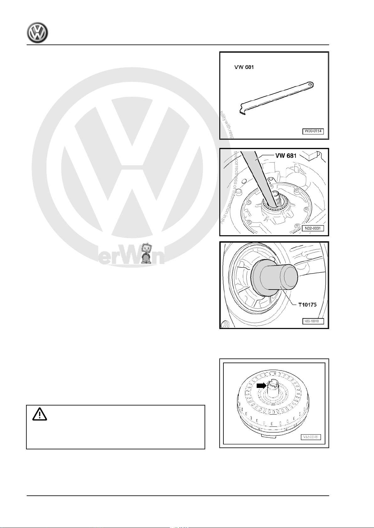
♦ Oil seal extractor lever -VW 681-
Removing
– Pry out seal with lever -VW 681- .
Installing
– Drive in seal flush thrust piece -T10175- .
1.4 Installing torque converter
– Carefully push on torque converter hub via oil seal to first stop.
– Turn torque converter towards gearbox using light pressure
until notch in hub -arrow- engages in follower of pump gear
and torque converter can be felt to slip in place.
The torque converter is properly inserted when it can easily be
turned by hand and is seated equally deep in gearbox around the
entire circumference.
Caution
If engine and gearbox are brought together with force because
the torque converter is improperly fitted, both gearbox and tor‐
que converter will be damaged.
10 Rep. Gr.32 - Torque converter

P
r
o
t
e
c
t
e
d
b
y
c
o
p
y
r
i
g
h
t
.
C
o
p
y
i
n
g
f
o
r
p
r
i
v
a
t
e
o
r
c
o
m
m
e
r
c
i
a
l
p
u
r
p
o
s
e
s
,
i
n
p
a
r
t
o
r
i
n
w
h
o
l
e
,
i
s
n
o
t
p
e
r
m
i
t
t
e
d
u
n
l
e
s
s
a
u
t
h
o
r
i
s
e
d
b
y
V
o
l
k
s
w
a
g
e
n
A
G
.
V
o
l
k
s
w
a
g
e
n
A
G
d
o
e
s
n
o
t
g
u
a
r
a
n
t
e
e
o
r
a
c
c
e
p
t
a
n
y
l
i
a
b
i
l
i
t
y
w
i
t
h
r
e
s
p
e
c
t
t
o
t
h
e
c
o
r
r
e
c
t
n
e
s
s
o
f
i
n
f
o
r
m
a
t
i
o
n
i
n
t
h
i
s
d
o
c
u
m
e
n
t
.
C
o
p
y
r
i
g
h
t
b
y
V
o
l
k
s
w
a
g
e
n
A
G
.
Golf Variant 2007 ➤ , Golf Variant 2010 ➤ , Jetta 2005 ➤ , Jetta 2011 ➤
6-speed automatic gearbox 09G - Edition 04.2010
37 – Controls, housing
1 Connecting “tester”
Volkswagen offers various devices such as
♦ Vehicle diagnosis, testing and information system -VAS 5051-
♦ Vehicle diagnosis, testing and information system -VAS
5051B-
♦ Tester -VAS 5051/11A-
♦ Vehicle diagnosis and service information system -VAS 5052-
♦ Diagnostic system -VAS 5053-
The operation of these “devices” is described in the respective
user's manuals.
The following description refers to the vehicle diagnosis, testing
and information system -VAS 5051- ⇒ page 11 .
1.1 Connecting vehicle diagnosis, testing
Special tools and workshop equipment required
♦ Vehicle diagnosis, testing and information system -VAS 5051-
and information system -VAS 5051-
WARNING
♦ During a road test, always secure testing and measuring
equipment on the back seat.
♦ These devices may be operated only by a passenger dur‐
ing a test drive.
– Push connector of diagnosis cable -VAS 5051/1- -2- or -
VAS 5051/3- onto diagnosis connection.
1. Connecting “tester” 11

P
r
o
t
e
c
t
e
d
b
y
c
o
p
y
r
i
g
h
t
.
C
o
p
y
i
n
g
f
o
r
p
r
i
v
a
t
e
o
r
c
o
m
m
e
r
c
i
a
l
p
u
r
p
o
s
e
s
,
i
n
p
a
r
t
o
r
i
n
w
h
o
l
e
,
i
s
n
o
t
p
e
r
m
i
t
t
e
d
u
n
l
e
s
s
a
u
t
h
o
r
i
s
e
d
b
y
V
o
l
k
s
w
a
g
e
n
A
G
.
V
o
l
k
s
w
a
g
e
n
A
G
d
o
e
s
n
o
t
g
u
a
r
a
n
t
e
e
o
r
a
c
c
e
p
t
a
n
y
l
i
a
b
i
l
i
t
y
w
i
t
h
r
e
s
p
e
c
t
t
o
t
h
e
c
o
r
r
e
c
t
n
e
s
s
o
f
i
n
f
o
r
m
a
t
i
o
n
i
n
t
h
i
s
d
o
c
u
m
e
n
t
.
C
o
p
y
r
i
g
h
t
b
y
V
o
l
k
s
w
a
g
e
n
A
G
.
Golf Variant 2007 ➤ , Golf Variant 2010 ➤ , Jetta 2005 ➤ , Jetta 2011 ➤
6-speed automatic gearbox 09G - Edition 04.2010
– Switch on “tester” -arrow-.
The “tester” is ready for use when it is possible to choose between
the buttons Guided functions and Guided fault finding on
the “right” of the screen.
Depending on equipment and version of the tester, other func‐
tions may be “displayed” such as:
♦ ElsaWin
♦ Testing
♦ Self-diagnosis
The “tester” is now ready for use.
– Switch on ignition.
– Touch a button on the screen to start the desired function.
12 Rep. Gr.37 - Controls, housing

P
r
o
t
e
c
t
e
d
b
y
c
o
p
y
r
i
g
h
t
.
C
o
p
y
i
n
g
f
o
r
p
r
i
v
a
t
e
o
r
c
o
m
m
e
r
c
i
a
l
p
u
r
p
o
s
e
s
,
i
n
p
a
r
t
o
r
i
n
w
h
o
l
e
,
i
s
n
o
t
p
e
r
m
i
t
t
e
d
u
n
l
e
s
s
a
u
t
h
o
r
i
s
e
d
b
y
V
o
l
k
s
w
a
g
e
n
A
G
.
V
o
l
k
s
w
a
g
e
n
A
G
d
o
e
s
n
o
t
g
u
a
r
a
n
t
e
e
o
r
a
c
c
e
p
t
a
n
y
l
i
a
b
i
l
i
t
y
w
i
t
h
r
e
s
p
e
c
t
t
o
t
h
e
c
o
r
r
e
c
t
n
e
s
s
o
f
i
n
f
o
r
m
a
t
i
o
n
i
n
t
h
i
s
d
o
c
u
m
e
n
t
.
C
o
p
y
r
i
g
h
t
b
y
V
o
l
k
s
w
a
g
e
n
A
G
.
Golf Variant 2007 ➤ , Golf Variant 2010 ➤ , Jetta 2005 ➤ , Jetta 2011 ➤
6-speed automatic gearbox 09G - Edition 04.2010
2 Electrical and electronic components and their locations
1 - Control unit for automatic
gearbox -J217-
❑ The control unit trans‐
mits and receives data
from the ⇒ data bus.
❑ Installation location in
Jetta 2005 ▸, Bora
2006 ▸, Golf Variant
2007 ▸, Jetta Wagon
2008 ▸ ⇒ page 14
❑ Installation location in
Jetta 2011 ▸ with 2.0 l 85 kW engine
⇒ page 15 .
❑ Installation location in
Jetta 2011 ▸ with 2.5 l 125 kW engine
⇒ page 15 .
❑ Can be checked using
“guided fault finding” of VAS 5051-
2 - Engine control unit
❑ The control unit trans‐
mits and receives data
from the data bus
❑ Location and removing
and installing ⇒ Rep.
Gr. 23 for the respective
engine code letter ⇒
Rep. Gr. 24 for the re‐
spective engine code
letter
3 - Multifunction switch -F125-
❑ Location ⇒ page 15
❑ Can be checked using
“guided fault finding” of VAS 5051-
❑ Removing, installing and adjusting ⇒ page 18 .
4 - Valve body
❑ Location ⇒ page 15
❑ Components can be checked using “guided fault finding” of -VAS 5051❑ Allocation ⇒ Electronic parts catalogue “ETKA”
5 - Wiring harness, 8-pin
❑ For senders
❑ With gearbox oil temperature sender -G93❑ Location ⇒ page 16
❑ Removing and installing ⇒ page 105
❑ Allocation ⇒ Electronic parts catalogue “ETKA”
6 - Gearbox oil temperature sender -G93-
❑ Location ⇒ page 16
❑ Can be checked using “guided fault finding” of -VAS 5051-
7 - Wiring harness, 14-pin
❑ For solenoid valves
2. Electrical and electronic components and their locations 13

P
r
o
t
e
c
t
e
d
b
y
c
o
p
y
r
i
g
h
t
.
C
o
p
y
i
n
g
f
o
r
p
r
i
v
a
t
e
o
r
c
o
m
m
e
r
c
i
a
l
p
u
r
p
o
s
e
s
,
i
n
p
a
r
t
o
r
i
n
w
h
o
l
e
,
i
s
n
o
t
p
e
r
m
i
t
t
e
d
u
n
l
e
s
s
a
u
t
h
o
r
i
s
e
d
b
y
V
o
l
k
s
w
a
g
e
n
A
G
.
V
o
l
k
s
w
a
g
e
n
A
G
d
o
e
s
n
o
t
g
u
a
r
a
n
t
e
e
o
r
a
c
c
e
p
t
a
n
y
l
i
a
b
i
l
i
t
y
w
i
t
h
r
e
s
p
e
c
t
t
o
t
h
e
c
o
r
r
e
c
t
n
e
s
s
o
f
i
n
f
o
r
m
a
t
i
o
n
i
n
t
h
i
s
d
o
c
u
m
e
n
t
.
C
o
p
y
r
i
g
h
t
b
y
V
o
l
k
s
w
a
g
e
n
A
G
.
Golf Variant 2007 ➤ , Golf Variant 2010 ➤ , Jetta 2005 ➤ , Jetta 2011 ➤
6-speed automatic gearbox 09G - Edition 04.2010
❑ Location ⇒ page 16
❑ Removing and installing ⇒ page 103
❑ Allocation ⇒ Electronic parts catalogue “ETKA”
8 - Hydraulic pressure sender 1 for automatic gearbox -G193-
❑ Not installed in all gearboxes
❑ Allocation ⇒ Electronic parts catalogue “ETKA”
❑ Location ⇒ page 16
9 - Hydraulic pressure sender 2 for automatic gearbox -G194-
❑ Not installed in all gearboxes
❑ Allocation ⇒ Electronic parts catalogue “ETKA”
❑ Location ⇒ page 16
10 - Gearbox input speed sender -G182-
❑ Location ⇒ page 17
❑ Removing and installing ⇒ page 106
❑ Can be checked using “guided fault finding” of -VAS 5051-
11 - Gearbox output speed sender -G195-
❑ Location ⇒ page 17
❑ Removing and installing ⇒ page 107
❑ Can be checked using “guided fault finding” of -VAS 5051-
12 - Selector lever lock solenoid -N110-
❑ Location: selector lever lock solenoid is located in the selector mechanism.
❑ Can be checked using “guided fault finding” of -VAS 5051-
13 - Tiptronic switch -F189-
❑ Location ⇒ page 17
❑ Can be checked using “guided fault finding” of -VAS 5051-
14 - Terminal 50 voltage supply relay -J682-
❑ In E box in engine compartment ⇒ Current flow diagrams, Electrical fault finding and Fitting locations.
15 - Diagnostic connection
❑ Location ⇒ page 17
16 - Selector lever position display -Y6-
❑ Location ⇒ page 17
❑ Removing and installing ⇒ Electrical system; Rep. Gr. 90 ; Gauges, instruments; Dash panel insert .
Automatic gearbox control unit -J217- -arrow- in Jetta 2005 ▸,
Bora 2006 ▸, Golf Variant 2007 ▸, Jetta Wagon 2008 ▸
Location: control unit is located in front left wheel housing.
– Wheel housing liner must be removed for removing and in‐
stalling.
14 Rep. Gr.37 - Controls, housing

P
r
o
t
e
c
t
e
d
b
y
c
o
p
y
r
i
g
h
t
.
C
o
p
y
i
n
g
f
o
r
p
r
i
v
a
t
e
o
r
c
o
m
m
e
r
c
i
a
l
p
u
r
p
o
s
e
s
,
i
n
p
a
r
t
o
r
i
n
w
h
o
l
e
,
i
s
n
o
t
p
e
r
m
i
t
t
e
d
u
n
l
e
s
s
a
u
t
h
o
r
i
s
e
d
b
y
V
o
l
k
s
w
a
g
e
n
A
G
.
V
o
l
k
s
w
a
g
e
n
A
G
d
o
e
s
n
o
t
g
u
a
r
a
n
t
e
e
o
r
a
c
c
e
p
t
a
n
y
l
i
a
b
i
l
i
t
y
w
i
t
h
r
e
s
p
e
c
t
t
o
t
h
e
c
o
r
r
e
c
t
n
e
s
s
o
f
i
n
f
o
r
m
a
t
i
o
n
i
n
t
h
i
s
d
o
c
u
m
e
n
t
.
C
o
p
y
r
i
g
h
t
b
y
V
o
l
k
s
w
a
g
e
n
A
G
.
Golf Variant 2007 ➤ , Golf Variant 2010 ➤ , Jetta 2005 ➤ , Jetta 2011 ➤
Automatic gearbox control unit -J217- -A- in Jetta 2011 ▸ with 2.0
l - 85 kW engine
Location: control unit is located in plenum chamber on right.
– Plenum chamber cover must be removed for removal and in‐
stallation ⇒ Rep. Gr. 50 ; Plenum chamber cover; Removing
and installing plenum chamber cover .
Automatic gearbox control unit -J217- -A- in Jetta 2011 ▸ with 2.5
l - 125 kW engine
Location: control unit is located in front left of engine compartment
next to battery.
Multifunction switch -F125-
6-speed automatic gearbox 09G - Edition 04.2010
Location: multifunction switch is located on top of the gearbox.
Valve body
Location: valve body is bolted to underside of gearbox housing
and covered by pan.
Solenoid valves -N88- , -N89- , -N90- , -N91- , -N92- , -N93- , N282- and -N283- are attached to valve body.
2. Electrical and electronic components and their locations 15

P
r
o
t
e
c
t
e
d
b
y
c
o
p
y
r
i
g
h
t
.
C
o
p
y
i
n
g
f
o
r
p
r
i
v
a
t
e
o
r
c
o
m
m
e
r
c
i
a
l
p
u
r
p
o
s
e
s
,
i
n
p
a
r
t
o
r
i
n
w
h
o
l
e
,
i
s
n
o
t
p
e
r
m
i
t
t
e
d
u
n
l
e
s
s
a
u
t
h
o
r
i
s
e
d
b
y
V
o
l
k
s
w
a
g
e
n
A
G
.
V
o
l
k
s
w
a
g
e
n
A
G
d
o
e
s
n
o
t
g
u
a
r
a
n
t
e
e
o
r
a
c
c
e
p
t
a
n
y
l
i
a
b
i
l
i
t
y
w
i
t
h
r
e
s
p
e
c
t
t
o
t
h
e
c
o
r
r
e
c
t
n
e
s
s
o
f
i
n
f
o
r
m
a
t
i
o
n
i
n
t
h
i
s
d
o
c
u
m
e
n
t
.
C
o
p
y
r
i
g
h
t
b
y
V
o
l
k
s
w
a
g
e
n
A
G
.
Golf Variant 2007 ➤ , Golf Variant 2010 ➤ , Jetta 2005 ➤ , Jetta 2011 ➤
6-speed automatic gearbox 09G - Edition 04.2010
Wiring harness, 8-pin
♦ Wiring harness for senders
♦ With integrated gearbox oil temperature sender -G93-
-arrow-
Location: wiring harness is attached to valve body in gearbox.
Wiring harness, 14-pin
♦ Wiring harness for solenoid valves.
Location: wiring harness is attached to valve body in gearbox.
Hydraulic pressure sender 1 for automatic gearbox -G193- and
hydraulic pressure sender 2 for automatic gearbox -G194-
This sender is not installed in all gearboxes.
Location:
Automatic gearbox hydraulic pressure sender 1 -G193- -1- and
automatic gearbox hydraulic pressure sender 2 -G194- -2- are
bolted into valve body.
16 Rep. Gr.37 - Controls, housing

P
r
o
t
e
c
t
e
d
b
y
c
o
p
y
r
i
g
h
t
.
C
o
p
y
i
n
g
f
o
r
p
r
i
v
a
t
e
o
r
c
o
m
m
e
r
c
i
a
l
p
u
r
p
o
s
e
s
,
i
n
p
a
r
t
o
r
i
n
w
h
o
l
e
,
i
s
n
o
t
p
e
r
m
i
t
t
e
d
u
n
l
e
s
s
a
u
t
h
o
r
i
s
e
d
b
y
V
o
l
k
s
w
a
g
e
n
A
G
.
V
o
l
k
s
w
a
g
e
n
A
G
d
o
e
s
n
o
t
g
u
a
r
a
n
t
e
e
o
r
a
c
c
e
p
t
a
n
y
l
i
a
b
i
l
i
t
y
w
i
t
h
r
e
s
p
e
c
t
t
o
t
h
e
c
o
r
r
e
c
t
n
e
s
s
o
f
i
n
f
o
r
m
a
t
i
o
n
i
n
t
h
i
s
d
o
c
u
m
e
n
t
.
C
o
p
y
r
i
g
h
t
b
y
V
o
l
k
s
w
a
g
e
n
A
G
.
Golf Variant 2007 ➤ , Golf Variant 2010 ➤ , Jetta 2005 ➤ , Jetta 2011 ➤
Gearbox input speed sender -G182- and gearbox output speed
sender -G195-
Location: senders are installed in gearbox housing above valve
body.
1 - Gearbox input speed sender -G182-
2 - Gearbox output speed sender -G195-
Tiptronic switch -F189-
Location: Tiptronic switch is integrated into selector mechanism.
In vehicles with a multifunction steering wheel, the buttons on the
steering wheel and their cable connections must also be checked.
6-speed automatic gearbox 09G - Edition 04.2010
Diagnostic connection
Location: diagnosis connector -arrow- is located on left below
driver storage compartment.
Selector lever position display -Y6-
Location: in dash panel insert
2. Electrical and electronic components and their locations 17

P
r
o
t
e
c
t
e
d
b
y
c
o
p
y
r
i
g
h
t
.
C
o
p
y
i
n
g
f
o
r
p
r
i
v
a
t
e
o
r
c
o
m
m
e
r
c
i
a
l
p
u
r
p
o
s
e
s
,
i
n
p
a
r
t
o
r
i
n
w
h
o
l
e
,
i
s
n
o
t
p
e
r
m
i
t
t
e
d
u
n
l
e
s
s
a
u
t
h
o
r
i
s
e
d
b
y
V
o
l
k
s
w
a
g
e
n
A
G
.
V
o
l
k
s
w
a
g
e
n
A
G
d
o
e
s
n
o
t
g
u
a
r
a
n
t
e
e
o
r
a
c
c
e
p
t
a
n
y
l
i
a
b
i
l
i
t
y
w
i
t
h
r
e
s
p
e
c
t
t
o
t
h
e
c
o
r
r
e
c
t
n
e
s
s
o
f
i
n
f
o
r
m
a
t
i
o
n
i
n
t
h
i
s
d
o
c
u
m
e
n
t
.
C
o
p
y
r
i
g
h
t
b
y
V
o
l
k
s
w
a
g
e
n
A
G
.
Golf Variant 2007 ➤ , Golf Variant 2010 ➤ , Jetta 2005 ➤ , Jetta 2011 ➤
6-speed automatic gearbox 09G - Edition 04.2010
3 Multifunction switch -F125-
Removing multifunction switch -F125- ⇒ page 18
Installing multifunction switch -F125- ⇒ page 19
Adjusting multifunction switch -F125- ⇒ page 20
3.1 Removing multifunction switch -F125-
Carry out procedure as follows:
– Move selector lever to position “N”.
– Switch off ignition.
– In order to remove selector lever cable from gearbox, first re‐
lease cable -arrows 1- and then remove it from cable support
bracket -arrow 2-.
Note
♦
Do not use any pliers, otherwise securing tabs on cable sup‐
port bracket could break off.
♦
Do not bend or kink selector lever cable.
– Lever cable -1- off lever -3- using an open jaw spanner -2-.
– Pull connector off multifunction switch -F125- .
– Unscrew nut -1-.
– Remove spring ring -2- and lever -3- from selector shaft -4-.
18 Rep. Gr.37 - Controls, housing

P
r
o
t
e
c
t
e
d
b
y
c
o
p
y
r
i
g
h
t
.
C
o
p
y
i
n
g
f
o
r
p
r
i
v
a
t
e
o
r
c
o
m
m
e
r
c
i
a
l
p
u
r
p
o
s
e
s
,
i
n
p
a
r
t
o
r
i
n
w
h
o
l
e
,
i
s
n
o
t
p
e
r
m
i
t
t
e
d
u
n
l
e
s
s
a
u
t
h
o
r
i
s
e
d
b
y
V
o
l
k
s
w
a
g
e
n
A
G
.
V
o
l
k
s
w
a
g
e
n
A
G
d
o
e
s
n
o
t
g
u
a
r
a
n
t
e
e
o
r
a
c
c
e
p
t
a
n
y
l
i
a
b
i
l
i
t
y
w
i
t
h
r
e
s
p
e
c
t
t
o
t
h
e
c
o
r
r
e
c
t
n
e
s
s
o
f
i
n
f
o
r
m
a
t
i
o
n
i
n
t
h
i
s
d
o
c
u
m
e
n
t
.
C
o
p
y
r
i
g
h
t
b
y
V
o
l
k
s
w
a
g
e
n
A
G
.
Golf Variant 2007 ➤ , Golf Variant 2010 ➤ , Jetta 2005 ➤ , Jetta 2011 ➤
6-speed automatic gearbox 09G - Edition 04.2010
– Carefully bend back hooks of lock washer -2- using a screw‐
driver.
– Renew securing clip if hooks have broken off.
– Unscrew nut -1-.
– Remove bolts -5-.
– Pull multifunction switch -4-, together with washers -2- and
-3-, off selector shaft -6-.
3.2 Installing multifunction switch -F125-
Special tools and workshop equipment required
♦ Torque wrench -V.A.G 1331-
Carry out procedure as follows:
Install in the reverse order of removal, observing the following:
– Place multifunction switch -4- on selector shaft -6-.
– Tighten securing bolts -5- for multifunction switch hand-tight.
– Bend hooks of lock washer -2- back.
– Put washers -2- and -3- on selector shaft -6-.
– Install washer -2- with hooks pointing up.
– Install washer -2- with long, narrow guides in long, narrow re‐
cesses of selector shaft -6-.
– Tighten nut -1- to 7 Nm.
– Secure nut -1- by bending up hooks on lock washer -2-.
– Renew securing clip if hooks have broken off.
3. Multifunction switch F125 19

P
r
o
t
e
c
t
e
d
b
y
c
o
p
y
r
i
g
h
t
.
C
o
p
y
i
n
g
f
o
r
p
r
i
v
a
t
e
o
r
c
o
m
m
e
r
c
i
a
l
p
u
r
p
o
s
e
s
,
i
n
p
a
r
t
o
r
i
n
w
h
o
l
e
,
i
s
n
o
t
p
e
r
m
i
t
t
e
d
u
n
l
e
s
s
a
u
t
h
o
r
i
s
e
d
b
y
V
o
l
k
s
w
a
g
e
n
A
G
.
V
o
l
k
s
w
a
g
e
n
A
G
d
o
e
s
n
o
t
g
u
a
r
a
n
t
e
e
o
r
a
c
c
e
p
t
a
n
y
l
i
a
b
i
l
i
t
y
w
i
t
h
r
e
s
p
e
c
t
t
o
t
h
e
c
o
r
r
e
c
t
n
e
s
s
o
f
i
n
f
o
r
m
a
t
i
o
n
i
n
t
h
i
s
d
o
c
u
m
e
n
t
.
C
o
p
y
r
i
g
h
t
b
y
V
o
l
k
s
w
a
g
e
n
A
G
.
Golf Variant 2007 ➤ , Golf Variant 2010 ➤ , Jetta 2005 ➤ , Jetta 2011 ➤
6-speed automatic gearbox 09G - Edition 04.2010
– Push lever -3- onto selector shaft -4-.
– Use lever -3- to shift gearbox to “P” position, i.e. press lever
-3- back (opposite direction of travel) to stop.
– Now use lever -3- to shift gearbox to “N” position. To do this,
push lever -3- two detent positions forwards in direction of
travel.
– Place spring ring -2- and nut -1- on selector shaft -4-.
– Tighten nut -1- to 13 Nm.
– Check selector mechanism ⇒ page 33 .
3.3 Adjusting multifunction switch -F125-
Special tools and workshop equipment required
♦ Setting gauge -T10173-
– Move selector lever to position “N”.
– Do not kink selector lever cable.
3.3.1 Adjustment prerequisites
• Selector lever cable is disconnected from selector shaft lever.
• Selector shaft is set to “N” position.
• Securing bolts for multifunction switch -F125- have been loos‐
ened.
• Selector shaft lever has been removed.
20 Rep. Gr.37 - Controls, housing

P
r
o
t
e
c
t
e
d
b
y
c
o
p
y
r
i
g
h
t
.
C
o
p
y
i
n
g
f
o
r
p
r
i
v
a
t
e
o
r
c
o
m
m
e
r
c
i
a
l
p
u
r
p
o
s
e
s
,
i
n
p
a
r
t
o
r
i
n
w
h
o
l
e
,
i
s
n
o
t
p
e
r
m
i
t
t
e
d
u
n
l
e
s
s
a
u
t
h
o
r
i
s
e
d
b
y
V
o
l
k
s
w
a
g
e
n
A
G
.
V
o
l
k
s
w
a
g
e
n
A
G
d
o
e
s
n
o
t
g
u
a
r
a
n
t
e
e
o
r
a
c
c
e
p
t
a
n
y
l
i
a
b
i
l
i
t
y
w
i
t
h
r
e
s
p
e
c
t
t
o
t
h
e
c
o
r
r
e
c
t
n
e
s
s
o
f
i
n
f
o
r
m
a
t
i
o
n
i
n
t
h
i
s
d
o
c
u
m
e
n
t
.
C
o
p
y
r
i
g
h
t
b
y
V
o
l
k
s
w
a
g
e
n
A
G
.
Golf Variant 2007 ➤ , Golf Variant 2010 ➤ , Jetta 2005 ➤ , Jetta 2011 ➤
6-speed automatic gearbox 09G - Edition 04.2010
Carry out procedure as follows:
– Place setting gauge on selector shaft -2- and turn multifunction
switch -1- until setting gauge engages in lug on multifunction
switch connector.
– Secure setting gauge on selector shaft -2- with bolt -3-.
– Tighten bolts -arrows- to 6 Nm.
– Remove setting gauge.
– Continue installation in reverse order of removal ⇒ page 19 .
3. Multifunction switch F125 21

P
r
o
t
e
c
t
e
d
b
y
c
o
p
y
r
i
g
h
t
.
C
o
p
y
i
n
g
f
o
r
p
r
i
v
a
t
e
o
r
c
o
m
m
e
r
c
i
a
l
p
u
r
p
o
s
e
s
,
i
n
p
a
r
t
o
r
i
n
w
h
o
l
e
,
i
s
n
o
t
p
e
r
m
i
t
t
e
d
u
n
l
e
s
s
a
u
t
h
o
r
i
s
e
d
b
y
V
o
l
k
s
w
a
g
e
n
A
G
.
V
o
l
k
s
w
a
g
e
n
A
G
d
o
e
s
n
o
t
g
u
a
r
a
n
t
e
e
o
r
a
c
c
e
p
t
a
n
y
l
i
a
b
i
l
i
t
y
w
i
t
h
r
e
s
p
e
c
t
t
o
t
h
e
c
o
r
r
e
c
t
n
e
s
s
o
f
i
n
f
o
r
m
a
t
i
o
n
i
n
t
h
i
s
d
o
c
u
m
e
n
t
.
C
o
p
y
r
i
g
h
t
b
y
V
o
l
k
s
w
a
g
e
n
A
G
.
Golf Variant 2007 ➤ , Golf Variant 2010 ➤ , Jetta 2005 ➤ , Jetta 2011 ➤
6-speed automatic gearbox 09G - Edition 04.2010
4 Selector mechanism up to 02.2009
WARNING
Before working on vehicle with engine running, move selector
lever into position “P” and apply handbrake.
Selector mechanism from 03.2009 onwards ⇒ page 35 .
4.1 Overview of selector mechanism up to 02.2009
1 - Selector cover with knob
❑ Do not remove knob
without reason. For
emergency release, on‐
ly the cover needs to be
unclipped ⇒ page 31 .
❑ Before removing knob,
pull button out past its
pressure point. Secure
button with cable tie or
appropriate wire against
being pressed in. This
will prevent the button
from being accidentally
pressed into the knob.
❑ If button is pressed into
removed handle
– Always pull out button
past the felt pressure
point before installing
knob.
2 - Selector mechanism with
selector lever
❑ Removing and installing
⇒ page 23
3 - Bolt with spring
❑ 3 Nm
4 - Pin
❑ Removing ⇒ page 23
❑ Do not grease
5 - Locking plate
❑ Always renew after re‐
moving
6 - Nut
❑ 9 Nm
❑ Qty. 4
7 - Selector housing
❑ With seal
8 - Selector lever cable
❑ Cable must not be greased
❑ Removing and installing ⇒ page 23
❑ Checking ⇒ page 30
22 Rep. Gr.37 - Controls, housing

P
r
o
t
e
c
t
e
d
b
y
c
o
p
y
r
i
g
h
t
.
C
o
p
y
i
n
g
f
o
r
p
r
i
v
a
t
e
o
r
c
o
m
m
e
r
c
i
a
l
p
u
r
p
o
s
e
s
,
i
n
p
a
r
t
o
r
i
n
w
h
o
l
e
,
i
s
n
o
t
p
e
r
m
i
t
t
e
d
u
n
l
e
s
s
a
u
t
h
o
r
i
s
e
d
b
y
V
o
l
k
s
w
a
g
e
n
A
G
.
V
o
l
k
s
w
a
g
e
n
A
G
d
o
e
s
n
o
t
g
u
a
r
a
n
t
e
e
o
r
a
c
c
e
p
t
a
n
y
l
i
a
b
i
l
i
t
y
w
i
t
h
r
e
s
p
e
c
t
t
o
t
h
e
c
o
r
r
e
c
t
n
e
s
s
o
f
i
n
f
o
r
m
a
t
i
o
n
i
n
t
h
i
s
d
o
c
u
m
e
n
t
.
C
o
p
y
r
i
g
h
t
b
y
V
o
l
k
s
w
a
g
e
n
A
G
.
Golf Variant 2007 ➤ , Golf Variant 2010 ➤ , Jetta 2005 ➤ , Jetta 2011 ➤
6-speed automatic gearbox 09G - Edition 04.2010
❑ Adjusting ⇒ page 30
9 - Hexagon nut with washer
❑ 8 Nm
❑ Qty. 4
4.2 Removing and installing selector mech‐
anism with selector lever up to 02.2009
Carry out procedure as follows:
Note
Following installation, selector lever cable must be checked for
ease of movement and be adjusted.
– Remove selector lever cable from gearbox ⇒ page 23 .
– Remove centre console ⇒ Rep. Gr. 68 ; Compartments, cov‐
ers and trims .
– Remove selector lever cable from gearbox ⇒ page 23 .
– Remove exhaust system below heat shield ⇒ Rep. Gr. 26 ;
Removing and installing parts of exhaust system .
– Remove heat shield beneath selector mechanism.
– Remove 4 nuts for selector mechanism “from above”.
Torque setting for nuts: 8 Nm
– Take selector mechanism out downwards.
– Check selector lever cable after installing ⇒ page 30 .
4.3 Removing and installing selector lever cable up to 02.2009
Carry out procedure as follows:
Note
Following installation, selector lever cable must be checked for
ease of movement and be adjusted.
Removing
– Move selector lever to position “S” position.
– In order to remove selector lever cable from gearbox, first re‐
lease cable -arrows 1- and then remove it from cable support
bracket -arrow 2-.
Note
♦
Do not use any pliers, otherwise securing tabs on cable sup‐
port bracket could break off.
♦
Do not bend or kink selector lever cable.
4. Selector mechanism up to 02.2009 23

P
r
o
t
e
c
t
e
d
b
y
c
o
p
y
r
i
g
h
t
.
C
o
p
y
i
n
g
f
o
r
p
r
i
v
a
t
e
o
r
c
o
m
m
e
r
c
i
a
l
p
u
r
p
o
s
e
s
,
i
n
p
a
r
t
o
r
i
n
w
h
o
l
e
,
i
s
n
o
t
p
e
r
m
i
t
t
e
d
u
n
l
e
s
s
a
u
t
h
o
r
i
s
e
d
b
y
V
o
l
k
s
w
a
g
e
n
A
G
.
V
o
l
k
s
w
a
g
e
n
A
G
d
o
e
s
n
o
t
g
u
a
r
a
n
t
e
e
o
r
a
c
c
e
p
t
a
n
y
l
i
a
b
i
l
i
t
y
w
i
t
h
r
e
s
p
e
c
t
t
o
t
h
e
c
o
r
r
e
c
t
n
e
s
s
o
f
i
n
f
o
r
m
a
t
i
o
n
i
n
t
h
i
s
d
o
c
u
m
e
n
t
.
C
o
p
y
r
i
g
h
t
b
y
V
o
l
k
s
w
a
g
e
n
A
G
.
Golf Variant 2007 ➤ , Golf Variant 2010 ➤ , Jetta 2005 ➤ , Jetta 2011 ➤
6-speed automatic gearbox 09G - Edition 04.2010
– Lever cable -1- off lever -3- using an open jaw spanner -2-.
– Raise vehicle.
To remove cable and/or selector mechanism, heat shield and, if
necessary, parts of exhaust system must be removed ⇒ Rep. Gr.
26 ; Removing and installing parts of exhaust system .
– Remove heat shield beneath selector mechanism.
– Remove -selector housing- beneath selector lever.
24 Rep. Gr.37 - Controls, housing

P
r
o
t
e
c
t
e
d
b
y
c
o
p
y
r
i
g
h
t
.
C
o
p
y
i
n
g
f
o
r
p
r
i
v
a
t
e
o
r
c
o
m
m
e
r
c
i
a
l
p
u
r
p
o
s
e
s
,
i
n
p
a
r
t
o
r
i
n
w
h
o
l
e
,
i
s
n
o
t
p
e
r
m
i
t
t
e
d
u
n
l
e
s
s
a
u
t
h
o
r
i
s
e
d
b
y
V
o
l
k
s
w
a
g
e
n
A
G
.
V
o
l
k
s
w
a
g
e
n
A
G
d
o
e
s
n
o
t
g
u
a
r
a
n
t
e
e
o
r
a
c
c
e
p
t
a
n
y
l
i
a
b
i
l
i
t
y
w
i
t
h
r
e
s
p
e
c
t
t
o
t
h
e
c
o
r
r
e
c
t
n
e
s
s
o
f
i
n
f
o
r
m
a
t
i
o
n
i
n
t
h
i
s
d
o
c
u
m
e
n
t
.
C
o
p
y
r
i
g
h
t
b
y
V
o
l
k
s
w
a
g
e
n
A
G
.
Golf Variant 2007 ➤ , Golf Variant 2010 ➤ , Jetta 2005 ➤ , Jetta 2011 ➤
6-speed automatic gearbox 09G - Edition 04.2010
– Remove locking plate for selector lever cable. Always renew
locking plate.
-Selector housing- is pushed forwards slightly on cable --.
To remove selector lever cable, securing tab must be pushed for‐
wards in -direction of arrow 1-.
– At same time, -pin- is pushed up with a screwdriver
-arrow 2-.
– Please insert -screwdriver- from underneath whilst pushing
securing tab forwards.
4. Selector mechanism up to 02.2009 25
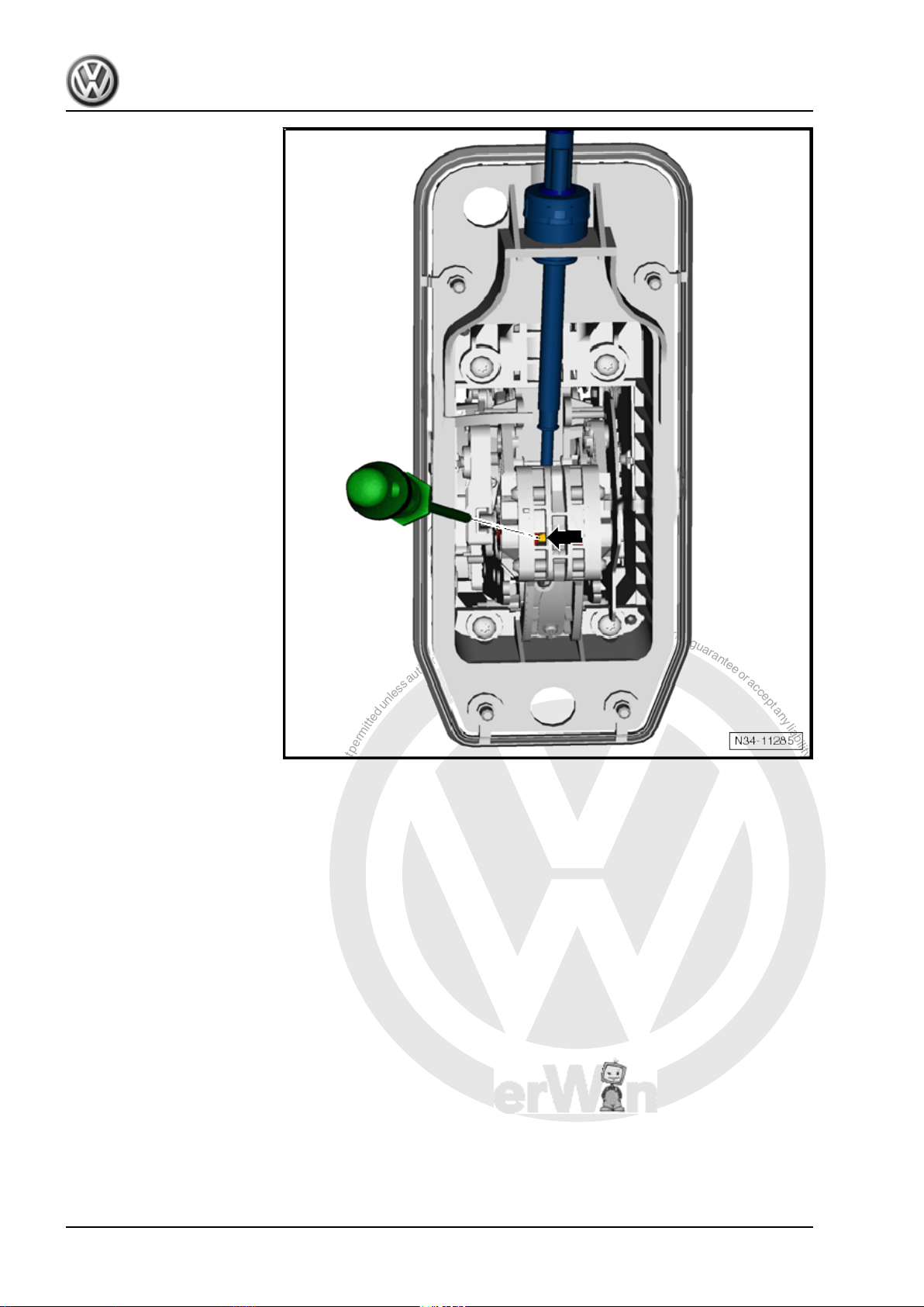
P
r
o
t
e
c
t
e
d
b
y
c
o
p
y
r
i
g
h
t
.
C
o
p
y
i
n
g
f
o
r
p
r
i
v
a
t
e
o
r
c
o
m
m
e
r
c
i
a
l
p
u
r
p
o
s
e
s
,
i
n
p
a
r
t
o
r
i
n
w
h
o
l
e
,
i
s
n
o
t
p
e
r
m
i
t
t
e
d
u
n
l
e
s
s
a
u
t
h
o
r
i
s
e
d
b
y
V
o
l
k
s
w
a
g
e
n
A
G
.
V
o
l
k
s
w
a
g
e
n
A
G
d
o
e
s
n
o
t
g
u
a
r
a
n
t
e
e
o
r
a
c
c
e
p
t
a
n
y
l
i
a
b
i
l
i
t
y
w
i
t
h
r
e
s
p
e
c
t
t
o
t
h
e
c
o
r
r
e
c
t
n
e
s
s
o
f
i
n
f
o
r
m
a
t
i
o
n
i
n
t
h
i
s
d
o
c
u
m
e
n
t
.
C
o
p
y
r
i
g
h
t
b
y
V
o
l
k
s
w
a
g
e
n
A
G
.
Golf Variant 2007 ➤ , Golf Variant 2010 ➤ , Jetta 2005 ➤ , Jetta 2011 ➤
6-speed automatic gearbox 09G - Edition 04.2010
Clarification:
♦ -1- Push tab forwards
♦ -2- Push pin up
26 Rep. Gr.37 - Controls, housing
 Loading...