

Page 1
2.8L VR6
Article Text
This file passed thru Volkswagen Technical Site - http://volkswagen.msk.ru
ARTICLE BEGINNING
1999-2000 ENGINES
Volkswagen 2.8L VR6 6-Cylinder
Golf, GTI, Jetta
* PLEASE READ THIS FIRST *
NOTE: For engine repair procedures not covered in this article,
see ENGINE OVERHAUL PROCEDURES - GENERAL INFORMATION article
in the GENERAL INFORMATION section.
ENGINE IDENTIFICATION
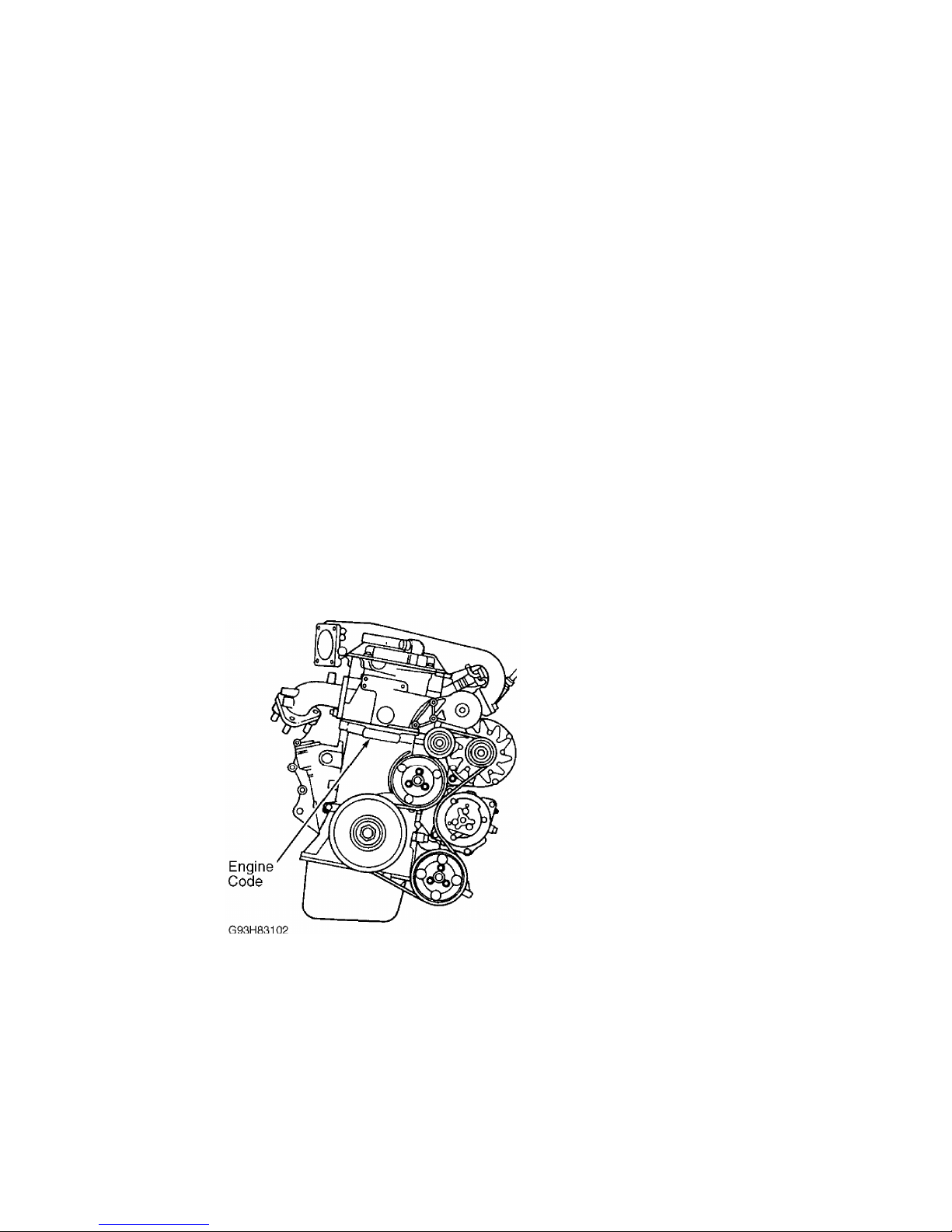
Engine identification number is stamped on a machined pad, on
front of the cylinder block. See Fig. 1. The engine code is also
listed on a sticker attached to the pulley side of the valve cover and
the vehicle identification sticker located in the luggage compartment.
ENGINE CODES
ДДДДДДДДДДДДДДДДДДДДДДДДДДДДДДДДДДДДДДДДДДДДДДДДДДДДДДДДДДДДДДДДДДДДД
Application Code
2.8L VR6 ...................................................... AAA
2.8L VR6 ...................................................... AFP
ДДДДДДДДДДДДДДДДДДДДДДДДДДДДДДДДДДДДДДДДДДДДДДДДДДДДДДДДДДДДДДДДДДДДД
Fig. 1: Locating Engine Identification Number
Courtesy of Volkswagen United States, Inc.
ADJUSTMENTS
VALVE CLEARANCE
Engine is equipped with hydraulic lifters. Adjustment is not
necessary.
TROUBLE SHOOTING
NOTE: See TROUBLE SHOOTING - BASIC PROCEDURES article in the
GENERAL TROUBLE SHOOTING section.
Page 2
REMOVAL & INSTALLATION
* PLEASE READ THIS FIRST *
NOTE: When battery is disconnected, vehicle computer and memory
systems may lose memory data. Driveability problems may exist
until computer systems have completed a relearn cycle.
NOTE: For reassembly reference, label all electrical connectors,
vacuum hoses and fuel lines before removal. Also place mating
marks on other major assemblies before removal.
WARNING: Radio/cassette or radio/CD player is equipped with an
anti-theft protection circuit. Whenever battery is
disconnected, radio will go into anti-theft mode. When
battery is reconnected, radio will display CODE, and will be
inoperative until proper code number is entered. Obtain
security code before disconnecting battery.
FUEL PRESSURE RELEASE
Remove fuel pump relay (lower right relay located in
fuse/relay panel). start engine and let idle until it stalls. Crank
engine for an additional 5 seconds. Reinstall fuel pump relay.
ENGINE
NOTE: Engine is removed with transaxle attached.
Removal
1) Obtain radio code. Turn ignition off and wait 20 seconds.
Disconnect negative battery cable. Remove air cleaner assembly.
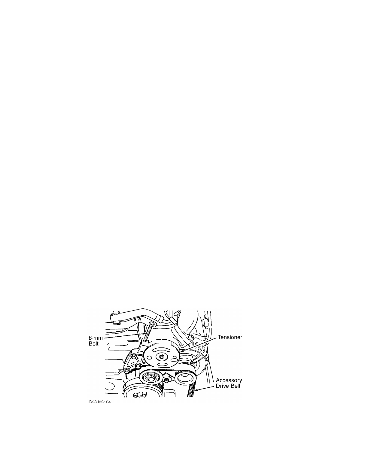
Install 8-mm bolt in belt tensioner hole and remove accessory drive
belt. See Fig. 2.
2) On manual transmission models, disconnect clutch slave
cylinder. On all models, remove power steering pump and attach to
body. DO NOT disconnect power steering hoses. Remove radiator, front
lock support and front bumper. Drain cooling system. Disconnect
cooling fan and thermoswitch.
Fig. 2: Releasing Accessory Drive Belt Tensioner
Courtesy of Volkswagen United States, Inc.
3) Label and disconnect all electrical wiring, control
cables, coolant hoses and vacuum hoses from engine/transaxle assembly.
Disconnect throttle, cruise and kickdown linkage (if equipped). Remove
air duct from intake manifold.
4) Disconnect drive axles from transaxle. See FWD AXLE SHAFTS
Page 3
article in DRIVE AXLES. Disconnect exhaust pipe from exhaust manifold.
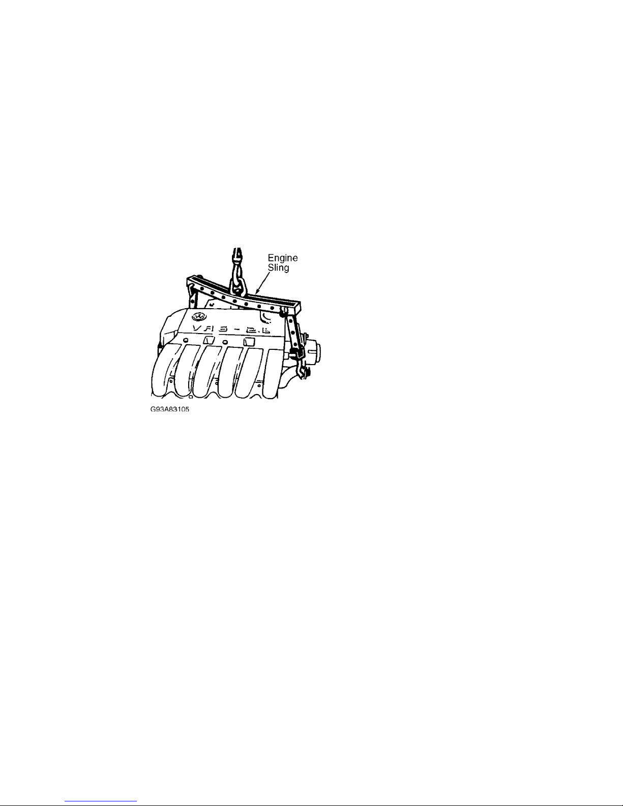
Attach Engine Sling (2024A). See Fig. 3.
5) Disconnect left rear transaxle mount and right rear engine
mount. Disconnect front engine mount. Release engine carrier. It may
be necessary to pry spacer bracket from rubber bushings. Raise engine
and transaxle out of vehicle.
Installation
To install, reverse removal procedure. Use NEW self-locking
nuts and coolant. Ensure engine mounts are installed to original
location. Align all engine supports with mount bushings before
tightening mount bolts. Tighten bolts to specification. See
TORQUE SPECIFICATIONS.
Fig. 3: Attaching Engine Sling
Courtesy of Volkswagen United States, Inc.
INTAKE & EXHAUST MANIFOLD
Removal and installation procedure is not available from
manufacturer. See TORQUE SPECIFICATIONS.
CYLINDER HEAD
Removal (GTI & Jetta - AAA Engine)
1) Remove upper engine cover. Remove wire guide. Remove right
rear support between upper intake manifold and cylinder head. Remove
fuel line bracket, flame trap coil and circlip. Remove wire brackets.
Remove valve cover and gasket. See Fig. 4.
Page 4
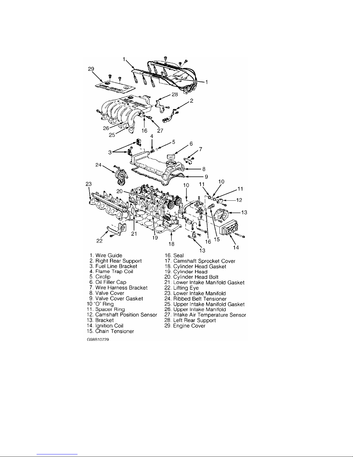
Fig. 4: Identifying 2.8L VR6 Cylinder Head (GTI & Jetta - AAA Engine)
Courtesy of Volkswagen United States, Inc.
2) Remove camshaft position sensor, "O" ring and spacer ring.
Remove bracket for 42-pin connector and water pump. Remove ignition
coil, chain tensioner and seal. Remove camshaft sprocket cover. Remove
cylinder head bolts in reverse order of installation. See Fig. 7.
Replace cylinder head bolts after loosening or removing.
Removal (Golf & Jetta - AFP Engine)
1) Remove engine cover. Remove upper intake manifold, fuel
line retainer, cylinder head and gasket. Remove Coolant Return Pump
(V51) and retainer. See Fig. 5. Remove ignition coil bolt and ignition
coil from cover.
2) Remove "O" ring, chain tensioner and seal ring from cover.
Remove cover bolts and cover from cylinder head. Remove thermostat
Page 5

housing retainer, seal, thermostat housing, O-ring and combination
valve from cylinder head.
3) Remove lower intake manifold bolts, both upper and lower
seals, and lower intake manifold. Remove cylinder head bolts in
reverse order of installation. See Fig. 7. Replace cylinder head bolt
after loosening or removing.
Fig. 5: Identifying 2.8L VR6 Cylinder Head (Golf & Jetta - AFP
Engine)
Courtesy of Volkswagen United States, Inc.
Inspection
Thoroughly clean all gasket mating surfaces. Check cylinder
head for warpage. Maximum warpage is .004" (.10 mm). Check minimum
cylinder head height and replace cylinder head (if necessary). See
Page 6
CYLINDER HEAD table under ENGINE SPECIFICATIONS.
NOTE: DO NOT reuse antifreeze after replacing cylinder block,
cylinder head, head gasket, radiator and/or heater core.
Installation
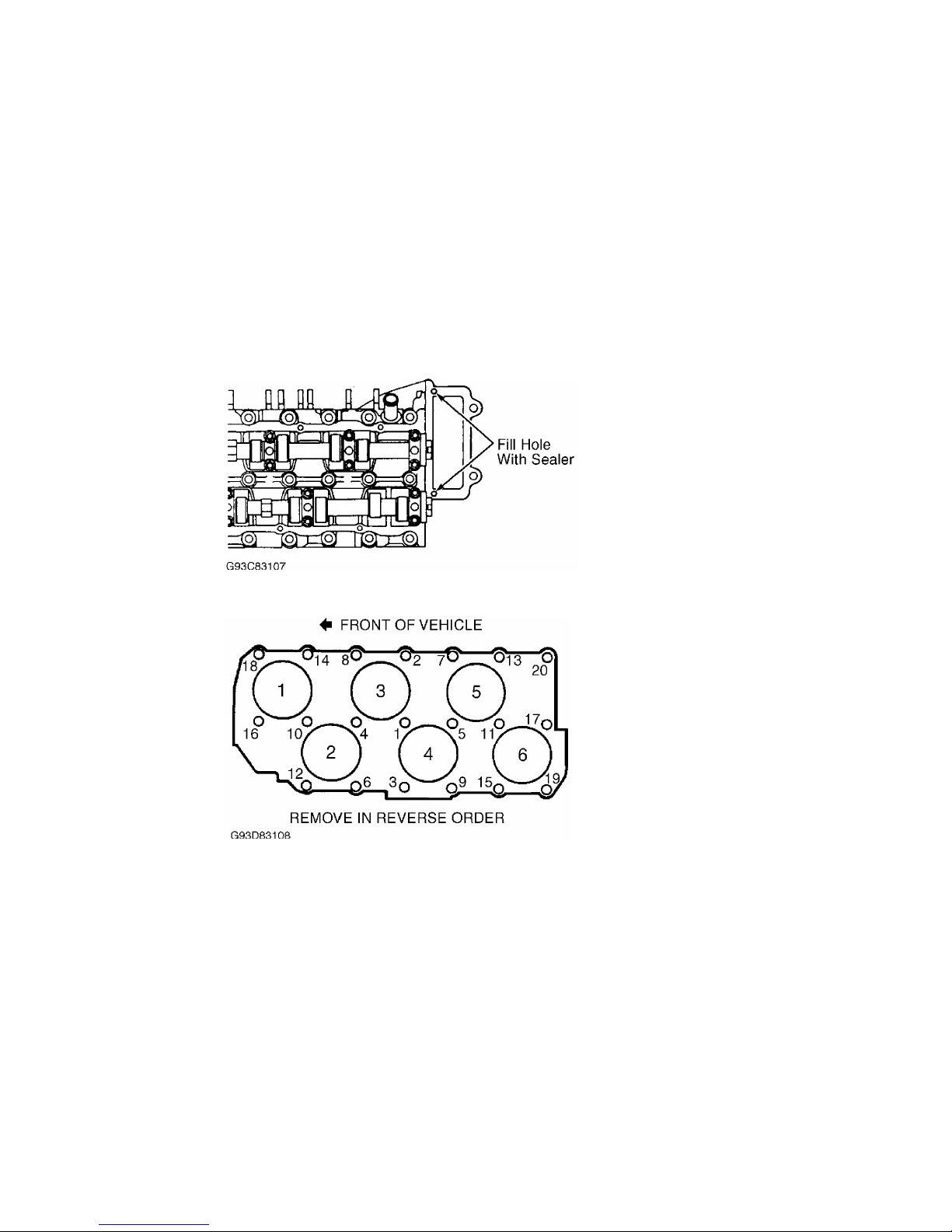
1) Remove sealer from the two 3-mm holes and replace with new
sealer. See Fig. 6. Install gasket onto guide pins. Guide pins should
be located near bolt holes No. 12 and 20. See Fig. 7.
2) Install cylinder head onto cylinder block. Do not use any
type of sealant. Install head bolts and tighten by hand. Tighten
cylinder head bolts in sequence (4 steps) to specification. See Fig. 7
. See TORQUE SPECIFICATIONS.
Fig. 6: Sealing Cylinder Head 3-mm Holes
Courtesy of Volkswagen United States, Inc.
Fig. 7: Cylinder Head Bolts Tightening Sequence
Courtesy of Volkswagen United States, Inc.
CRANKSHAFT OIL SEAL
Removal
Install 8-mm bolt in belt tensioner hole and remove accessory
drive belt. See Fig. 2. Remove vibration damper. Loosen inner section
of Oil Seal Extractor (3203) about 3 turns (4 mm) and lock in position
with knurled screw. Turn inner section of oil seal extractor until
seal is removed.
Installation
Place Guide Sleeve (3266/1) on crankshaft. Push oil seal over
guide sleeve. Using Oil Seal Installer (3266) and vibration damper
bolt, press oil seal in completely. See Fig. 8. Reverse removal
procedure to complete installation.
Page 7
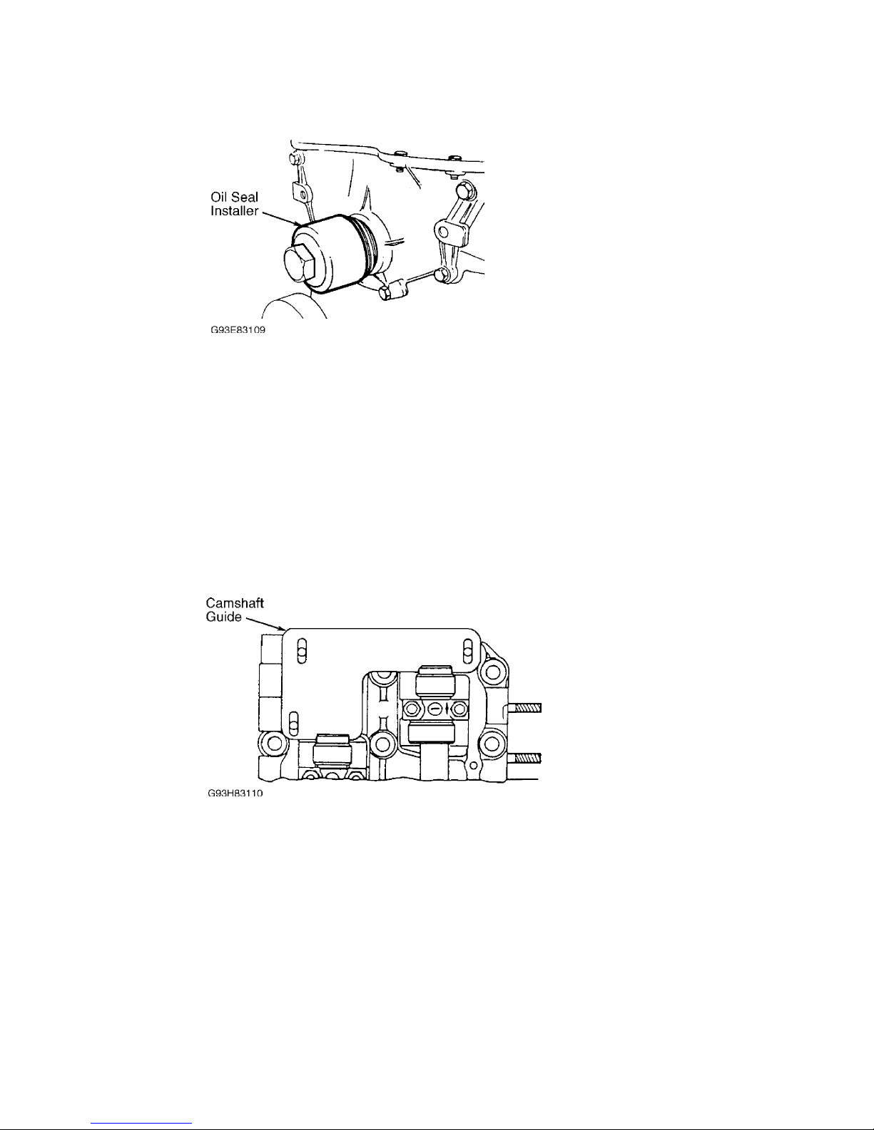
Fig. 8: Installing Crankshaft Oil Seal
Courtesy of Volkswagen United States, Inc.
TIMING CHAIN
Removal
1) Removal and installation procedure is not available from
manufacturer. Ensure crankshaft is aligned at TDC. Remove transaxle
and bellhousing assembly. Remove torque converter or clutch assembly
(as applicable). Remove valve cover. Remove camshaft sprocket cover
and intermediate shaft cover. Match mark all components to ensure
reassembly in original position.
2) Mark timing chains for direction of rotation. Align and
install Camshaft Guide (3268) onto cylinder head bolts. See Fig. 9.
Remove upper and lower chain tensioners. If necessary, remove
intermediate sprocket and camshaft sprocket bolts. Remove the timing
chain. See Fig. 10.
Fig. 9: Installing Camshaft Guide Onto Cylinder Head
Courtesy of Volkswagen United States, Inc.
Page 8
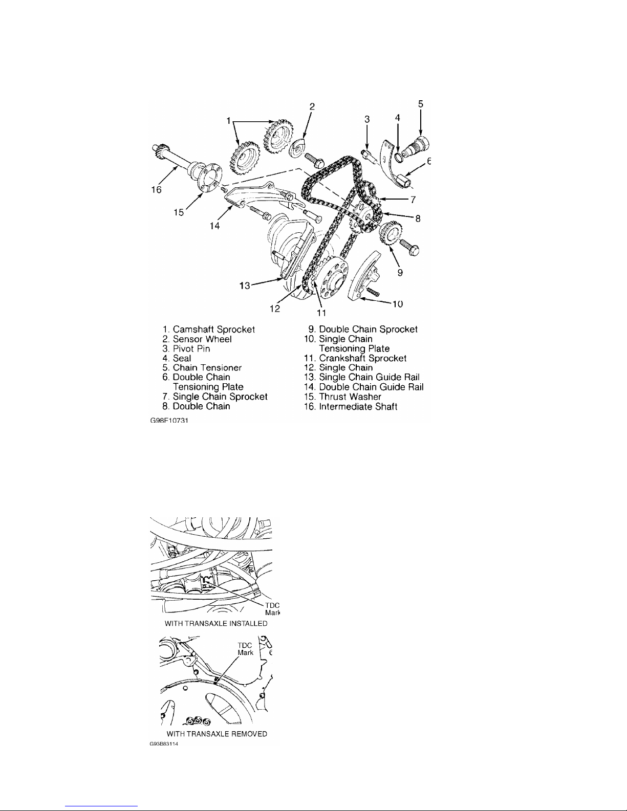
Fig. 10: Exploded View Of Timing Chain & Related Components
Courtesy of Volkswagen United States, Inc.
Installation
Leave Camshaft Guide (3268) installed. Ensure crankshaft is
aligned at TDC. See Figs. 11or 12. Ensure intermediate shaft is
correctly aligned. See Fig. 13. Install timing chain on sprockets.
Reverse removal procedure to complete installation
Fig. 11: Aligning Crankshaft At TDC (GTI & Jetta - AAA Engine)
Courtesy of Volkswagen United States, Inc.
Page 9
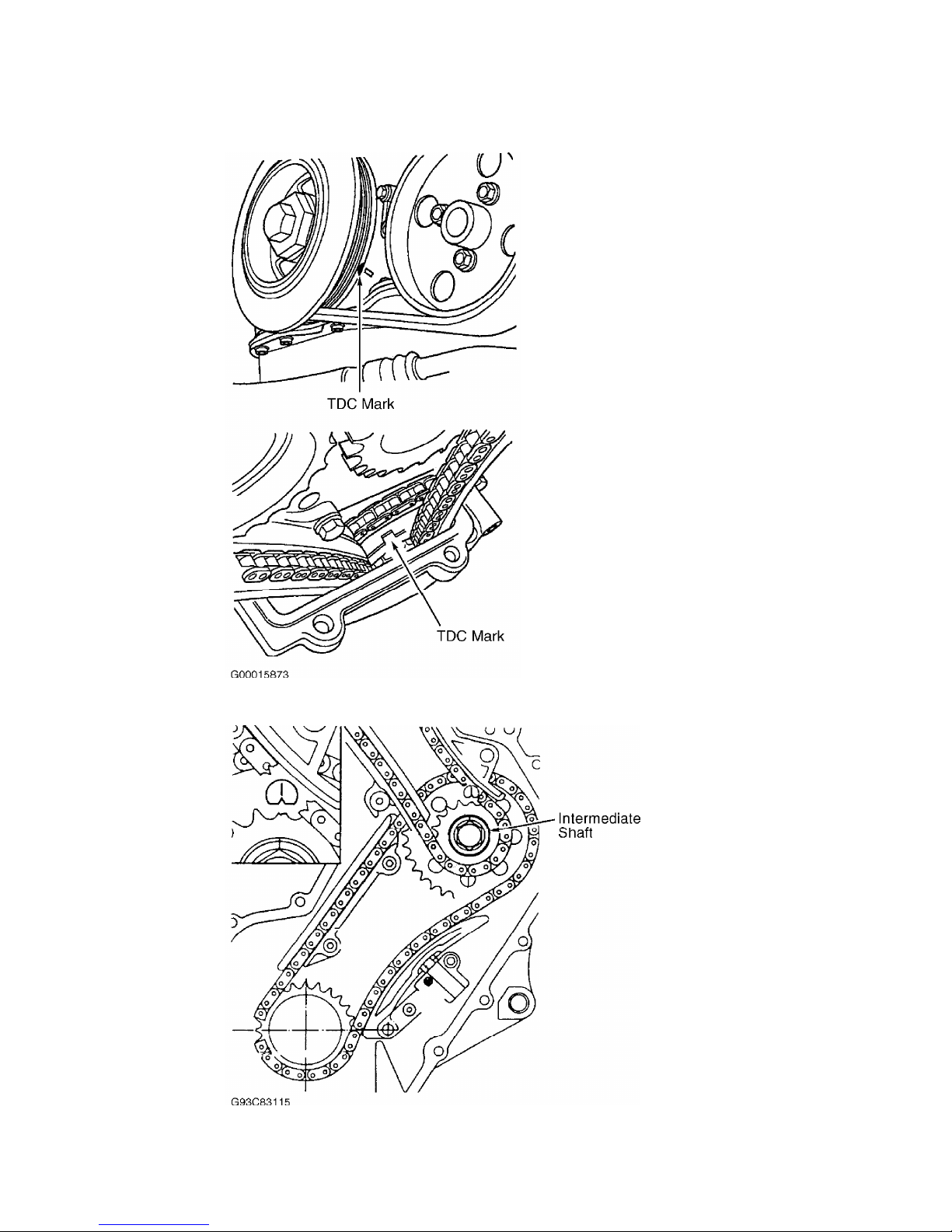
Fig. 12: Aligning Crankshaft At TDC (Golf & Jetta - AFP Engine)
Courtesy of Volkswagen United States, Inc.
Fig. 13: Aligning Intermediate Shaft At TDC
Courtesy of Volkswagen United States, Inc.
CAMSHAFT
Page 10
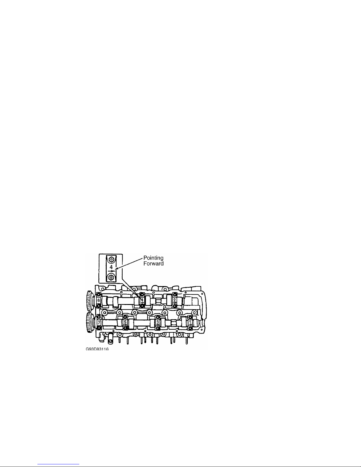
Removal
Remove valve cover. Place crankshaft at TDC. Remove ignition
coil. Remove double chain tensioner. Remove camshaft sprocket cover
with camshaft position sensor attached. Remove camshaft sprockets.
Mark timing chains for direction of rotation. If removing camshaft for
cylinders No. 1, 3 and 5, remove bearing caps No. 1 and 7 first, then
remove bearing caps No. 3 and 5. If removing camshaft for cylinders
No. 2, 4 and 6, remove bearing cap No. 4 first, then remove bearing
caps No. 2 and 6. Remove camshafts.
Inspection
Check camshaft bearing oil clearance. See CAMSHAFT table
under ENGINE SPECIFICATIONS. If oil clearance exceeds specification,
install new camshaft and recheck clearance. If clearance still exceeds
specification, replace cylinder head.
Installation
1) Lubricate all contact surfaces. When installing bearing
caps, ensure identification mark on bearing cap is readable from
exhaust manifold side and arrow points toward vibration damper. See
Fig. 14.
2) If installing camshaft for cylinders No. 1, 3 and 5,
tighten bearing caps No. 3 and 5 alternately in a diagonal sequence to
15 ft. lbs. (20 N.m). Repeat procedure for bearing caps No. 1 and 7.
3) If installing camshaft for cylinders No. 2, 4 and 6,
tighten bearing caps No. 2 and 6 alternately in a diagonal sequence to
15 ft. lbs. (20 N.m). Repeat procedure for bearing cap No. 4.
4) To complete installation, reverse removal procedure.
Ensure timing marks are properly aligned. If lifters are charged with
oil, allow 30 minutes for lifters to bleed down before starting
engine. Otherwise valves may come in contact with pistons.
Fig. 14: Installing Camshafts Into Cylinder Head
Courtesy of Volkswagen United States, Inc.
VALVE LIFTERS
Removal & Installation
Remove camshaft. See CAMSHAFT. Remove valve lifters from
cylinder head. Note position of each lifter. If lifters are reused,
they MUST be installed in original position. If replacement lifters
are charged with oil, allow 30 minutes for lifters to bleed down
before starting engine. Otherwise, valves may come in contact with
pistons. To complete installation, reverse removal procedure.
WATER PUMP
NOTE: Coolant/water mixture should be used at all times.
Page 11

Removal (GTI & Jetta - AAA Engine)
1) Obtain radio security code. Turn ignition off and wait for
20 seconds. Disconnect negative battery cable. Drain cooling system.
Disconnect front exhaust pipe from catalytic converter.
2) Install 8-mm bolt in belt tensioner hole and remove drive
belt. See Fig. 2. Remove ignition cable guide. Disconnect front and
rear motor mounts. Attach Engine Sling (2024A) to engine. See Fig. 3.
3) Lift engine enough to access water pump. Secure pulley
using Spanner Wrench (VAG 1590). Remove water pump bolts. Push engine
toward left side and remove water pump.
Installation
When installing motor mounts, ensure recess on engine bracket
fits into mounting tab of bonded rubber bushing. Hand tighten motor
mount bolts and light rock engine to ensure motor mounts are fully
seated. To complete installation, reverse removal procedure.
Removal & Installation (Golf & Jetta - AFP Engine)
1) Obtain radio security code. Turn ignition off and wait for
20 seconds. Disconnect negative battery cable. Drain cooling system.
2) Remove accessory belt. Remove pulley retaining bolts and
pulley from Coolant pump. Remove coolant pump bolts and coolant pump
from engine block.
3) To install, reverse removal procedure. Tighten bolts to
specification. See TORQUE SPECIFICATIONS.
OIL PAN
Removal & Installation
1) Remove center, left and right damping pans. Drain oil.
Remove oil pan bolts. Remove oil pan using a rubber hammer if
necessary. Remove sealant residue from cylinder block and oil pan.
Ensure surfaces are free from grease and oil.
2) To install, apply 2-3 mm thick silicone bead around
sealing surface of oil pan. Immediately install oil pan and lightly
tighten all bolts. Ensure oil pan is flush with cylinder block.
Tighten bolts to specification. See TORQUE SPECIFICATIONS. To complete
installation, reverse removal procedures. Allow sealer to dry 30
minutes before installing engine oil.
OVERHAUL
CYLINDER HEAD
Cylinder Head
Clean all gasket mating surfaces. Check cylinder head for
warpage. Ensure warpage does not exceed .0039" (.100 mm).
Valve Stem Oil Seals
With valve springs removed, remove oil seals using Valve Seal
Remover (3047A). To install new oil seal, slide plastic sleeve over
valve stem. Lubricate new oil seal. Using Valve Seal Installer (3129),
push oil seal on valve guide.
Valve Guides
1) Check valve-to-guide clearance specification. See
CYLINDER HEAD table under ENGINE SPECIFICATIONS. If valve guides have
previously been replaced, replace cylinder head.
2) To replace valve guide, press guide out from camshaft
side. Lubricate guide and press in cold cylinder head (from camshaft
side) until shoulder makes contact. DO NOT exceed one ton pressure.
Ream guides to proper valve-to-guide clearance. See CYLINDER HEAD
table under ENGINE SPECIFICATIONS.
Page 12

Valve Seats
1) Check valve seats before any other cylinder head service.
Insert valve and hold firmly against valve seat. Measure valve stem
tip-to-cylinder head distance. See Fig. 15. This measurement
determines installed valve height. Subtract measured distance from
minimum specification. See MINIMUM VALVE INSTALLED HEIGHT table.
2) The difference is maximum refacing allowable for valve and
seat. If valve installed height is too low or too high, lifters will
not work correctly. Replace cylinder head assembly.
MINIMUM VALVE INSTALLED HEIGHT
ДДДДДДДДДДДДДДДДДДДДДДДДДДДДДДДДДДДДДДДДДДДДДДДДДДДДДДДДДДДДДДДДДДДДД
Application In. (mm)
Intake Valve .......................................... 1.33 (33.9)
Exhaust Valve ......................................... 1.34 (34.1)
ДДДДДДДДДДДДДДДДДДДДДДДДДДДДДДДДДДДДДДДДДДДДДДДДДДДДДДДДДДДДДДДДДДДДД
Fig. 15: Measuring Installed Valve Height
Courtesy of Volkswagen United States, Inc.
Valves
Measure valve length, stem diameter and valve margin. If not
within specification, replace valves. Lap valves by hand or replace as
necessary. See VALVES table under ENGINE SPECIFICATIONS.
HYDRAULIC LIFTER TEST
To determine weak or noisy lifter, position camshaft lobe
high point upward. Using a piece of wood, push lifter down. See
Fig. 16. If lifter moves down more than .004" (.10 mm), replace
lifter. If lifter moves less than .004" (.10 mm), lifter is okay.
Repeat procedure for remaining lifters.
CAUTION: If new lifters have been installed, engine must not be
started for 30 minutes. Otherwise, valves may come in contact
with pistons.
Fig. 16: Depressing Lifter
Courtesy of Volkswagen United States, Inc.
Page 13
CYLINDER BLOCK ASSEMBLY
Piston & Rod Assembly
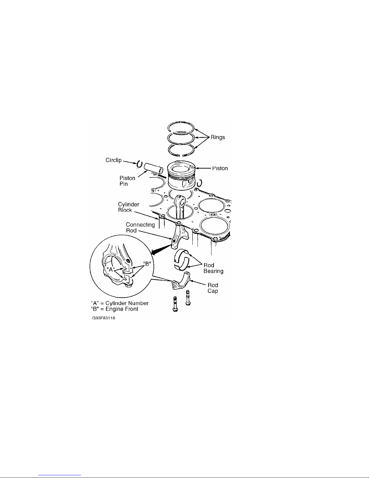
1) Ensure piston, rod and rod caps are marked with matching
cylinder number prior to removal. Ensure arrow on top of piston points
toward pulleys. Ensure marks on rod and cap are positioned correctly.
See Fig. 17. Rod cap bolts and nuts must be replaced after removing or
loosening.
Fig. 17: Assembling Piston & Rod
Courtesy of Volkswagen United States, Inc.
2) Mark piston in relation to pin. Remove circlips from ends
of pin bore. Use Piston Pin Replacer/Installer (VW 222A) to remove and
install piston pin. If pin is too tight, heat piston to 140øF (60øC).
Ensure rod is properly positioned with piston.
Fitting Pistons
Measure clearances with cylinder block supported on work
bench. Check clearance of piston-to-cylinder bore. Piston diameter is
stamped on top of piston in millimeters.
PISTON-TO-CYLINDER BORE DIMENSIONS
ДДДДДДДДДДДДДДДДДДДДДДДДДДДДДДДДДДДДДДДДДДДДДДДДДДДДДДДДДДДДДДДДДДДД
Size Piston Diameter In. (mm) Cylinder Bore In. (mm)
Standard ......... 3.188 (80.98) ................. 3.189 (81.01)
1st Over ......... 3.208 (81.49) ................. 3.209 (81.51)
2nd Over ......... 3.228 (81.98) ................. 3.229 (82.01)
ДДДДДДДДДДДДДДДДДДДДДДДДДДДДДДДДДДДДДДДДДДДДДДДДДДДДДДДДДДДДДДДДДДДД
Page 14
Piston Rings
1) Measure ring end gap. Measure ring side clearance between
ring and piston. Replace if necessary. See PISTONS, PINS & RINGS table
under ENGINE SPECIFICATIONS.
2) Install rings on piston with TOP mark facing upward.
Recessed edge on outside of center ring must face piston pin (down).
Position ring gaps on piston at 120-degree intervals.
Connecting Rod Bearings
Mark rod caps for reinstallation. Use Plastigage to measure
bearing clearances. Measure connecting rod side play. Replace or
machine as necessary. See CRANKSHAFT, MAIN & CONNECTING ROD BEARINGS
table under ENGINE SPECIFICATIONS. Tighten evenly to specification in
several steps. See TORQUE SPECIFICATIONS.
Crankshaft & Main Bearings
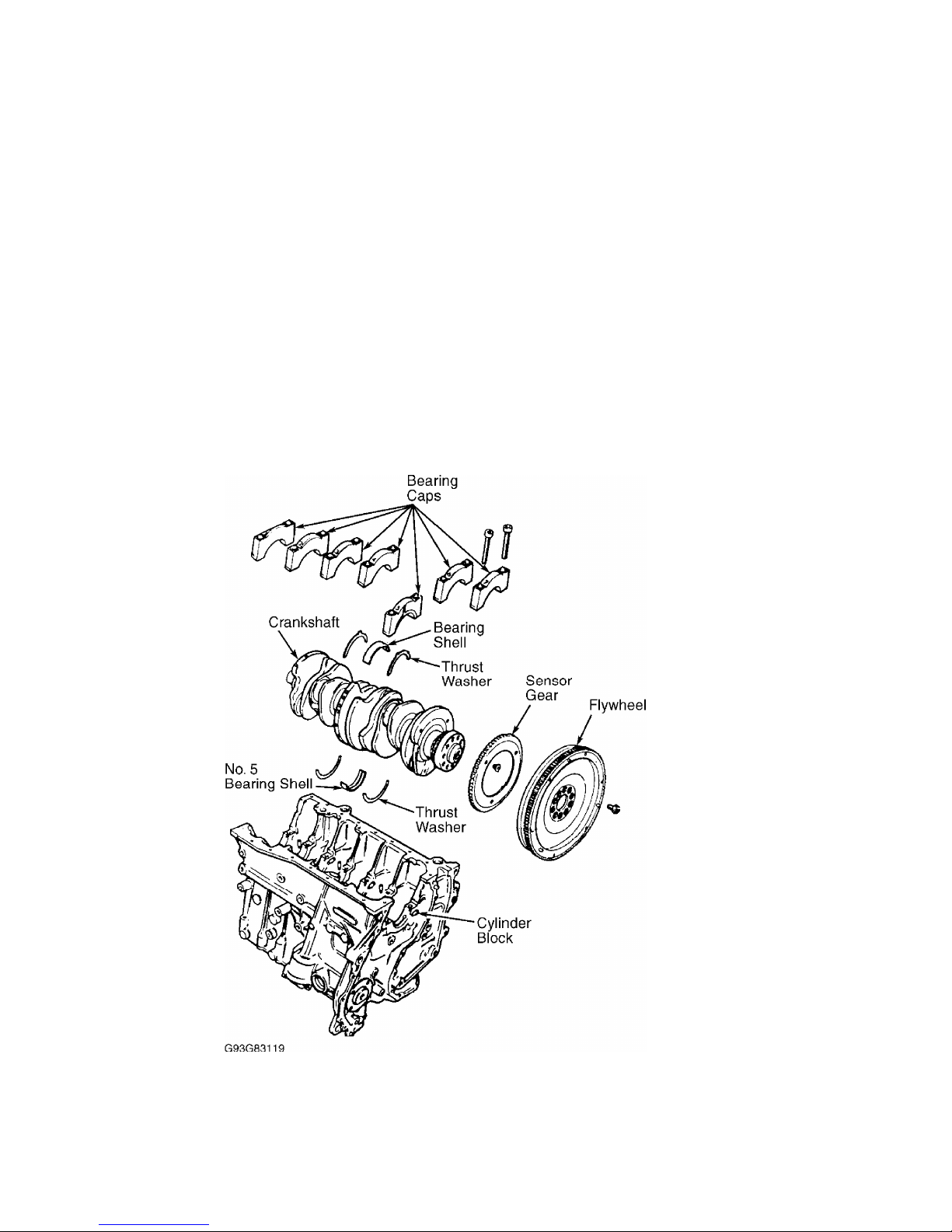
Main bearing caps are marked with matching journal for
installation in original position. See Fig. 18. Measure crankshaft end
play. See THRUST BEARING.
Fig. 18: Exploded View Of Crankshaft Assembly
Courtesy of Volkswagen United States, Inc.
Thrust Bearing
Insert feeler gauge between No. 5 main bearing and crankshaft
thrust face to measure end play. See Fig. 18. Replace thrust bearing
as necessary. See CRANKSHAFT, MAIN & CONNECTING ROD BEARINGS table
under ENGINE SPECIFICATIONS.
Page 15
Cylinder Block
Check cylinder bore for wear, out-of-round and taper. Check
cylinder block for warpage. See CYLINDER BLOCK table under ENGINE
SPECIFICATIONS.
ENGINE OILING
ENGINE LUBRICATION SYSTEM
Crankcase Capacity
See CRANKCASE CAPACITY table.
CRANKCASE CAPACITY
ДДДДДДДДДДДДДДДДДДДДДДДДДДДДДДДДДДДДДДДДДДДДДДДДДДДДДДДДДДДДДДДДДДДДД
With Filter Without Filter
Engine Code Replacement Replacement
AAA ................ 5.8 Qts. (5.5L) ............ 5.3 Qts. (5.0L)
AFP ................ 6.4 Qts. (6.1L) ............ 5.9 Qts. (5.6L)
ДДДДДДДДДДДДДДДДДДДДДДДДДДДДДДДДДДДДДДДДДДДДДДДДДДДДДДДДДДДДДДДДДДДДД
Oil Pressure
Check oil pressure with engine at warm operating temperature.
Minimum oil pressure at 2000 RPM is 29 psi (2.0 kg/cmý). If oil
pressure is incorrect, check oil pump and oil pressure relief valve.
OIL PUMP
Removal & Installation
Remove oil pan. Remove oil pump attaching bolts and remove
oil pump assembly. To install, reverse removal procedure.
Inspection
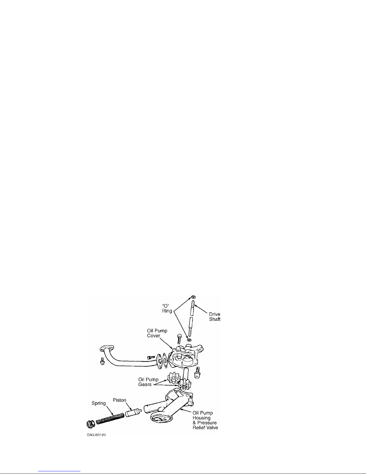
Check oil pump housing, gears and pressure relief valve for
damage or excessive wear. See Fig. 19. Repair or replace as an
assembly.
Fig. 19: Oil Pump Assembly
Courtesy of Volkswagen United States, Inc.
Page 16

TORQUE SPECIFICATIONS
TORQUE SPECIFICATIONS
ДДДДДДДДДДДДДДДДДДДДДДДДДДДДДДДДДДДДДДДДДДДДДДДДДДДДДДДДДДДДДДДДДДДДД
Application Ft. Lbs. (N.m)
A/C Bracket-To-Engine Bolt ................................ 18 (25)
Axle Shaft-To-Transaxle Drive Flange Bolt ................. 33 (45)
Camshaft Bearing Cap Bolt ................................. 15 (20)
Camshaft Sprocket Bolt ................................... 74 (100)
Connecting Rod Bolt
Step 1 .................................................. 22 (30)
Step 2 ......................... Additional 1/4 Turn (90 Degrees)
Crankshaft Main Bearing Cap Bolt
Step 1 .................................................. 22 (30)
Step 2 ........................ Additional 1/2 Turn (180 Degrees)
Cylinder Head Bolt (1)
Step 1 .................................................. 30 (40)
Step 2 .................................................. 44 (60)
Step 3 ......................... Additional 1/4 Turn (90 Degrees)
Step 4 ......................... Additional 1/4 Turn (90 Degrees)
Engine Bracket (Front) .................................... 44 (60)
Engine Bracket (To Body) .................................. 44 (60)
Engine-To-Transaxle
M12 Bolt ................................................ 59 (80)
M10 Bolt ................................................ 44 (60)
M7 Bolt ..................................................... (2)
M6 Bolt ........................................................
Fig. 2
Exhaust Manifold-To-Cylinder Head Bolt & Nut .............. 18 (25)
Exhaust Pipe-To-Catalytic Converter Bolt .................. 18 (25)
Exhaust Pipe-To-Manifold Nut .............................. 30 (40)
Flywheel-To-Crankshaft Bolt
Step 1 .................................................. 44 (60)
Step 2 ......................... Additional 1/4 Turn (90 Degrees)
Guide Rail Bolt ........................................... 15 (20)
Intake Manifold ........................................... 18 (25)
Intermediate Shaft Sprocket Bolt ......................... 74 (100)
Oil Pan Bolt .............................................. 11 (15)
Oil Pan Drain Plug ........................................ 22 (30)
Oil Pressure Switch ....................................... 18 (25)
Oil Pump Cover Long Bolt ...................................... (2)
Oil Pump Cover Short Bolt ................................. 18 (25)
Power Steering Pump Bracket Bolt .......................... 18 (25)
Pressure Plate Bolt ....................................... 15 (20)
Starter Mount Bolt ........................................ 44 (60)
Timing Chain (Double Row) Tensioner Nut ................... 22 (30)
Torque Converter-To-Carrier Plate Bolt .................... 22 (30)
Vibration Damper Bolt
Step 1 ................................................. 89 (120)
Step 2 ......................... Additional 1/4 Turn (90 Degrees)
Water Pump Pulley Bolt .................................... 18 (25)
Water Pump Housing-To-Engine Bolt ......................... 15 (20)
INCH Lbs. (N.m)
Fuel Rail Bolt (Lower) .................................... 89 (10)
Intermediate Shaft Retainer Plate Bolt .................... 89 (10)
Sensor Wheel Bolt
Step 1 .................................................. 89 (10)
Step 2 ......................... Additional 1/4 Turn (90 Degrees)
Timing Chain (Single Row) Tensioner Bolt .................. 89 (10)
Valve Cover Retaining Nut ................................. 89 (10)
Page 17

(1) - Never reuse cylinder head bolt(s) when servicing.
(2) - Tighten bolt to 89 INCH lbs. (10 N.m).
ДДДДДДДДДДДДДДДДДДДДДДДДДДДДДДДДДДДДДДДДДДДДДДДДДДДДДДДДДДДДДДДДДДДДД
ENGINE SPECIFICATIONS
GENERAL SPECIFICATIONS
GENERAL SPECIFICATIONS
ДДДДДДДДДДДДДДДДДДДДДДДДДДДДДДДДДДДДДДДДДДДДДДДДДДДДДДДДДДДДДДДДДДДДД
Application Specification
Displacement ................................... 170 Cu. In. (2.8L)
Bore .............................................. 3.19" (81.0 mm)
Stroke ............................................ 3.56" (90.3 mm)
Compression Ratio .......................................... 10.0:1
Fuel System .......................................... Motronic SFI
ДДДДДДДДДДДДДДДДДДДДДДДДДДДДДДДДДДДДДДДДДДДДДДДДДДДДДДДДДДДДДДДДДДДДД
CRANKSHAFT, MAIN & CONNECTING ROD BEARINGS
CRANKSHAFT, MAIN & CONNECTING ROD BEARINGS
ДДДДДДДДДДДДДДДДДДДДДДДДДДДДДДДДДДДДДДДДДДДДДДДДДДДДДДДДДДДДДДДДДДДДД
Application In. (mm)
Crankshaft
End Play
Standard .................................. .003-.009 (.07-.23)
Service Limit ...................................... .012 (.30)
Runout ............................................... .001 (.03)
Main Bearings
Journal Diameter .................... 2.361-2.362 (59.958-59.978)
Journal Out-Of-Round ................................. .001 (.03)
Journal Taper ........................................ .001 (.03)
Oil Clearance
Standard ................................ .0008-.0020 (.02-.06)
Service Limit .................................... .0039 (.100)
Connecting Rod Bearings
Journal Diameter .................... 2.124-2.125 (53.958-53.978)
Journal Out-Of-Round ................................. .001 (.03)
Journal Taper ........................................ .001 (.03)
Oil Clearance
Standard ................................ .0004-.0020 (.01-.06)
Service Limit .................................... .0039 (.100)
ДДДДДДДДДДДДДДДДДДДДДДДДДДДДДДДДДДДДДДДДДДДДДДДДДДДДДДДДДДДДДДДДДДДДД
PISTONS, PINS & RINGS
PISTONS, PINS & RINGS
ДДДДДДДДДДДДДДДДДДДДДДДДДДДДДДДДДДДДДДДДДДДДДДДДДДДДДДДДДДДДДДДДДДДДД
Application In. (mm)
Pistons
Clearance .......................................... .0016 (.040)
Diameter .......................................... 3.188 (80.99)
Pins
Diameter .................................................... (1)
Piston Fit ..................................... Interference Fit
Rod Fit ........................................ Interference Fit
Rings
No. 1
End Gap
Standard ................................ .008-.016 (.20-.40)
Page 18

Service Limit .................................. .0039 (.100)
Side Clearance
Standard ................................ .001-.003 (.02-.07)
Service Limit .................................... .006 (.15)
No. 2
End Gap
Standard ................................ .008-.016 (.20-.40)
Service Limit .................................. .0039 (.100)
Side Clearance
Standard ................................ .001-.003 (.02-.07)
Service Limit .................................... .006 (.15)
No. 3 (Oil)
End Gap
Standard ................................ .010-.020 (.25-.50)
Service Limit .................................. .0039 (.100)
Side Clearance ............................ .001-.002 (.02-.05)
(1) - Information is not available from manufacturer.
ДДДДДДДДДДДДДДДДДДДДДДДДДДДДДДДДДДДДДДДДДДДДДДДДДДДДДДДДДДДДДДДДДДДДД
CYLINDER BLOCK
CYLINDER BLOCK
ДДДДДДДДДДДДДДДДДДДДДДДДДДДДДДДДДДДДДДДДДДДДДДДДДДДДДДДДДДДДДДДДДДДДД
Application In. (mm)
Cylinder Bore
Standard Diameter ................................. 3.189 (81.01)
Maximum Taper ....................................... .0032 (.08)
Maximum Out-Of-Round ................................. .001 (.03)
ДДДДДДДДДДДДДДДДДДДДДДДДДДДДДДДДДДДДДДДДДДДДДДДДДДДДДДДДДДДДДДДДДДДДД
OIL PUMP
OIL PUMP
ДДДДДДДДДДДДДДДДДДДДДДДДДДДДДДДДДДДДДДДДДДДДДДДДДДДДДДДДДДДДДДДДДДДДД
Application Specification
Pump Gear Clearance
Radial (Maximum) ................................. .008" (.20 mm)
Axial (Maximum) ................................ .0039" (.100 mm)
ДДДДДДДДДДДДДДДДДДДДДДДДДДДДДДДДДДДДДДДДДДДДДДДДДДДДДДДДДДДДДДДДДДДДД
VALVES
VALVES
ДДДДДДДДДДДДДДДДДДДДДДДДДДДДДДДДДДДДДДДДДДДДДДДДДДДДДДДДДДДДДДДДДДДДД
Application Specification
Intake Valves
Face Angle .................................................. 45
ø
Head Diameter ................................. 1.535" (39.00 mm)
Length ...................................... 4.1713" (105.95 mm)
Minimum Margin (1) .......................................... (2)
Stem Diameter .................................. .2744" (6.97 mm)
Exhaust Valves
Face Angle .................................................. 45
ø
Head Diameter ................................. 1.346" (34.20 mm)
Length ...................................... 4.2106" (106.95 mm)
Minimum Margin (1) .......................................... (2)
Stem Diameter .................................. .2736" (6.95 mm)
(1) - DO NOT machine valves; hand lap only.
(2) - Information is not available from manufacturer.
Page 19

ДДДДДДДДДДДДДДДДДДДДДДДДДДДДДДДДДДДДДДДДДДДДДДДДДДДДДДДДДДДДДДДДДДДДД
CYLINDER HEAD
CYLINDER HEAD
ДДДДДДДДДДДДДДДДДДДДДДДДДДДДДДДДДДДДДДДДДДДДДДДДДДДДДДДДДДДДДДДДДДДДД
Application Specification
Cylinder Head Height (Minimum) .................. 5.492" (139.5 mm)
Maximum Warpage .................................. .0039" (.100 mm)
Valve Seats
Intake Valve
Seat Angle ................................................ 45
ø
Seat Width ............................ .055-.079" (1.4-2.0 mm)
Exhaust Valve
Seat Angle ................................................ 45
ø
Seat Width ............................ .079-.098" (2.0-2.5 mm)
Valve Guides
Intake Valve
Valve Guide Installed Height .............................. (1)
Oil Clearance .............................. (2) .040" (1.0 mm)
Exhaust Valve
Valve Guide Installed Height .............................. (1)
Valve Stem-To-Guide Oil Clearance ......... (2) .051" (1.30 mm)
(1) - Valve guide shoulder flush with cylinder head.
(2) - New valve installed in cylinder head. Dial indicator used
to measure valve rock in guide.
ДДДДДДДДДДДДДДДДДДДДДДДДДДДДДДДДДДДДДДДДДДДДДДДДДДДДДДДДДДДДДДДДДДДДД
CAMSHAFT
CAMSHAFT
ДДДДДДДДДДДДДДДДДДДДДДДДДДДДДДДДДДДДДДДДДДДДДДДДДДДДДДДДДДДДДДДДДДДДД
Application In. (mm)
End Play ............................................... .006 (.15)
Oil Clearance ................................ .0039 (.100) Maximum
Runout ........................................ .0004 (.01) Maximum
ДДДДДДДДДДДДДДДДДДДДДДДДДДДДДДДДДДДДДДДДДДДДДДДДДДДДДДДДДДДДДДДДДДДДД
END OF ARTICLE
 Loading...