


Volkswagen Golf 2004 User Manual
P
r
o
t
e
c
t
e
d
b
y
c
o
p
y
r
i
g
h
t
.
C
o
p
y
i
n
g
f
o
r
p
r
i
v
a
t
e
o
r
c
o
m
m
e
r
c
i
a
l
p
u
r
p
o
s
e
s
,
i
n
p
a
r
t
o
r
i
n
w
h
o
l
e
,
i
s
n
o
t
p
e
r
m
i
t
t
e
d
u
n
l
e
s
s
a
u
t
h
o
r
i
s
e
d
b
y
V
o
l
k
s
w
a
g
e
n
A
G
.
V
o
l
k
s
w
a
g
e
n
A
G
d
o
e
s
n
o
t
g
u
a
r
a
n
t
e
e
o
r
a
c
c
e
p
t
a
n
y
l
i
a
b
i
l
i
t
y
w
i
t
h
r
e
s
p
e
c
t
t
o
t
h
e
c
o
r
r
e
c
t
n
e
s
s
o
f
i
n
f
o
r
m
a
t
i
o
n
i
n
t
h
i
s
d
o
c
u
m
e
n
t
.
C
o
p
y
r
i
g
h
t
b
y
V
o
l
k
s
w
a
g
e
n
A
G
.
Service
Workshop Manual
Golf 2004 ➤
Heating, air conditioning
Edition 02.2008
Service Department. Technical Information

P
r
o
t
e
c
t
e
d
b
y
c
o
p
y
r
i
g
h
t
.
C
o
p
y
i
n
g
f
o
r
p
r
i
v
a
t
e
o
r
c
o
m
m
e
r
c
i
a
l
p
u
r
p
o
s
e
s
,
i
n
p
a
r
t
o
r
i
n
w
h
o
l
e
,
i
s
n
o
t
p
e
r
m
i
t
t
e
d
u
n
l
e
s
s
a
u
t
h
o
r
i
s
e
d
b
y
V
o
l
k
s
w
a
g
e
n
A
G
.
V
o
l
k
s
w
a
g
e
n
A
G
d
o
e
s
n
o
t
g
u
a
r
a
n
t
e
e
o
r
a
c
c
e
p
t
a
n
y
l
i
a
b
i
l
i
t
y
w
i
t
h
r
e
s
p
e
c
t
t
o
t
h
e
c
o
r
r
e
c
t
n
e
s
s
o
f
i
n
f
o
r
m
a
t
i
o
n
i
n
t
h
i
s
d
o
c
u
m
e
n
t
.
C
o
p
y
r
i
g
h
t
b
y
V
o
l
k
s
w
a
g
e
n
A
G
.
Service
List of Workshop Manual Repair GroupsList of Workshop Manual
Repair GroupsList of Workshop Manual Repair Groups
Re pa ir G ro up
80 - Heating
87 - Air conditioning system
Technical information should always be available to the foremen and mechanics, because their
careful and constant adherence to the instructions is essential to ensure vehicle road-worthiness and
safety. In addition, the normal basic safety precautions for working on motor vehicles must, as a
matter of course, be observed.
All rights reserved.
No reproduction without prior agreement from publisher.
Copyright © 2010 Volkswagen AG, Wolfsburg K0058991220

P
r
o
t
e
c
t
e
d
b
y
c
o
p
y
r
i
g
h
t
.
C
o
p
y
i
n
g
f
o
r
p
r
i
v
a
t
e
o
r
c
o
m
m
e
r
c
i
a
l
p
u
r
p
o
s
e
s
,
i
n
p
a
r
t
o
r
i
n
w
h
o
l
e
,
i
s
n
o
t
p
e
r
m
i
t
t
e
d
u
n
l
e
s
s
a
u
t
h
o
r
i
s
e
d
b
y
V
o
l
k
s
w
a
g
e
n
A
G
.
V
o
l
k
s
w
a
g
e
n
A
G
d
o
e
s
n
o
t
g
u
a
r
a
n
t
e
e
o
r
a
c
c
e
p
t
a
n
y
l
i
a
b
i
l
i
t
y
w
i
t
h
r
e
s
p
e
c
t
t
o
t
h
e
c
o
r
r
e
c
t
n
e
s
s
o
f
i
n
f
o
r
m
a
t
i
o
n
i
n
t
h
i
s
d
o
c
u
m
e
n
t
.
C
o
p
y
r
i
g
h
t
b
y
V
o
l
k
s
w
a
g
e
n
A
G
.
Golf 2004 ➤
Heating, air conditioning - Edition 02.2008
Contents
80 - Heating . . . . . . . . . . . . . . . . . . . . . . . . . . . . . . . . . . . . . . . . . . . . . . . . . . . . . . . . . . 1
1 Repairing heater . . . . . . . . . . . . . . . . . . . . . . . . . . . . . . . . . . . . . . . . . . . . . . . . . . . . . . . . . . 1
1.1 Passenger compartment heating . . . . . . . . . . . . . . . . . . . . . . . . . . . . . . . . . . . . . . . . . . . . 1
1.2 Removing fresh air blower V2 . . . . . . . . . . . . . . . . . . . . . . . . . . . . . . . . . . . . . . . . . . . . . . 3
1.3 Removing and installing fresh air blower series resistor with overheating fuse N24 . . . . . . 3
1.4 Removing and installing dust and pollen filter . . . . . . . . . . . . . . . . . . . . . . . . . . . . . . . . . . 4
1.5 Removing vents . . . . . . . . . . . . . . . . . . . . . . . . . . . . . . . . . . . . . . . . . . . . . . . . . . . . . . . . . . 4
1.6 Removing and installing controls for heated and fresh air . . . . . . . . . . . . . . . . . . . . . . . . . . 7
1.7 Connectors on controls for heated and fresh air . . . . . . . . . . . . . . . . . . . . . . . . . . . . . . . . 8
1.8 Removing and installing flexible shaft for air distribution . . . . . . . . . . . . . . . . . . . . . . . . . . 9
1.9 Removing and installing Bowden cable for temperature flap . . . . . . . . . . . . . . . . . . . . . . . . 10
1.10 Removing and installing fresh air and air recirculation flap control motor V154 . . . . . . . . 11
1.11 Removing and installing heat exchanger . . . . . . . . . . . . . . . . . . . . . . . . . . . . . . . . . . . . . . 12
1.12 Removing and installing auxiliary air heater element Z35 on vehicles up to 1K-7P015628 and
1.13 Removing and installing auxiliary air heater element Z35 on vehicles from 1K-7P015629 und
1.14 Checking ventilation . . . . . . . . . . . . . . . . . . . . . . . . . . . . . . . . . . . . . . . . . . . . . . . . . . . . . . 18
1.15 Removing and installing air intake screen . . . . . . . . . . . . . . . . . . . . . . . . . . . . . . . . . . . . . . 18
1.16 Removing and installing heater unit . . . . . . . . . . . . . . . . . . . . . . . . . . . . . . . . . . . . . . . . . . 19
2 Dismantling and assembling heater unit . . . . . . . . . . . . . . . . . . . . . . . . . . . . . . . . . . . . . . 23
2.1 Assembly overview – heater unit . . . . . . . . . . . . . . . . . . . . . . . . . . . . . . . . . . . . . . . . . . . . 23
2.2 Removing and installing air distribution housing . . . . . . . . . . . . . . . . . . . . . . . . . . . . . . . . 24
2.3 Dismantling and assembling heater unit . . . . . . . . . . . . . . . . . . . . . . . . . . . . . . . . . . . . . . 25
2.4 Removing and installing air distribution flap actuator . . . . . . . . . . . . . . . . . . . . . . . . . . . . . . 26
2.5 Removing and installing temperature flap actuator . . . . . . . . . . . . . . . . . . . . . . . . . . . . . . 26
87 - Air conditioning system . . . . . . . . . . . . . . . . . . . . . . . . . . . . . . . . . . . . . . . . . . . . 28
1 Notes on repair work to vehicles with air conditioning and on handling refrigerant . . . . . . 28
2 Air conditioning system with manual controls “Climatic” . . . . . . . . . . . . . . . . . . . . . . . . . . 29
1K-7B084800 . . . . . . . . . . . . . . . . . . . . . . . . . . . . . . . . . . . . . . . . . . . . . . . . . . . . . . . . . . . . 15
1K-7B084801 . . . . . . . . . . . . . . . . . . . . . . . . . . . . . . . . . . . . . . . . . . . . . . . . . . . . . . . . . . . . 16
2.1 Air conditioning and heating - passenger compartment . . . . . . . . . . . . . . . . . . . . . . . . . . . . 29
2.2 Dismantling and assembling heater and air conditioner unit “Climatic” . . . . . . . . . . . . . . . . 31
2.3 Removing and installing heating and air conditioning controls, “Climatic” with air conditioning
system control unit J301 . . . . . . . . . . . . . . . . . . . . . . . . . . . . . . . . . . . . . . . . . . . . . . . . . . 33
2.4 Connectors on controls for heating and air conditioning “Climatic” . . . . . . . . . . . . . . . . . . 33
2.5 Removing and installing flexible shaft for air distribution . . . . . . . . . . . . . . . . . . . . . . . . . . 35
2.6 Checking condensation water drainage hose on heater and air conditioner unit . . . . . . . . 36
2.7 Removing and installing air recirculation flap control motor V113 . . . . . . . . . . . . . . . . . . . . 36
2.8 Removing and installing temperature flap control motor V68 . . . . . . . . . . . . . . . . . . . . . . 36
2.9 Removing and installing footwell vent temperature sender G192 . . . . . . . . . . . . . . . . . . . . 38
2.10 Removing and installing centre vent temperature sender G191 . . . . . . . . . . . . . . . . . . . . 39
2.11 Ambient temperature sensor G17 . . . . . . . . . . . . . . . . . . . . . . . . . . . . . . . . . . . . . . . . . . . . 39
3 Air conditioning system with automatic regulation “Climatronic” . . . . . . . . . . . . . . . . . . . . 41
3.1 Procedure for checking and adjusting components . . . . . . . . . . . . . . . . . . . . . . . . . . . . . . 42
3.2 Function of operating and display unit for Climatronic air conditioning system E87 . . . . . . 43
3.3 Removing and installing operating and display unit for Climatronic air conditioning system
E87 with Climatronic control unit J255 . . . . . . . . . . . . . . . . . . . . . . . . . . . . . . . . . . . . . . . . 44
3.4 Connectors on Climatronic control unit J255 . . . . . . . . . . . . . . . . . . . . . . . . . . . . . . . . . . . . 45
3.5 Climatronic - passenger compartment . . . . . . . . . . . . . . . . . . . . . . . . . . . . . . . . . . . . . . . . 47
3.6 Dismantling and assembling heater and air conditioner unit “Climatronic” . . . . . . . . . . . . 50
3.7 Assembly overview - evaporator housing . . . . . . . . . . . . . . . . . . . . . . . . . . . . . . . . . . . . . . 52
3.8 Removing and installing fresh air blower control unit J126 . . . . . . . . . . . . . . . . . . . . . . . . 53
3.9 Removing and installing left footwell vent temperature sender G261 . . . . . . . . . . . . . . . . 54
Contents i

P
r
o
t
e
c
t
e
d
b
y
c
o
p
y
r
i
g
h
t
.
C
o
p
y
i
n
g
f
o
r
p
r
i
v
a
t
e
o
r
c
o
m
m
e
r
c
i
a
l
p
u
r
p
o
s
e
s
,
i
n
p
a
r
t
o
r
i
n
w
h
o
l
e
,
i
s
n
o
t
p
e
r
m
i
t
t
e
d
u
n
l
e
s
s
a
u
t
h
o
r
i
s
e
d
b
y
V
o
l
k
s
w
a
g
e
n
A
G
.
V
o
l
k
s
w
a
g
e
n
A
G
d
o
e
s
n
o
t
g
u
a
r
a
n
t
e
e
o
r
a
c
c
e
p
t
a
n
y
l
i
a
b
i
l
i
t
y
w
i
t
h
r
e
s
p
e
c
t
t
o
t
h
e
c
o
r
r
e
c
t
n
e
s
s
o
f
i
n
f
o
r
m
a
t
i
o
n
i
n
t
h
i
s
d
o
c
u
m
e
n
t
.
C
o
p
y
r
i
g
h
t
b
y
V
o
l
k
s
w
a
g
e
n
A
G
.
Golf 2004 ➤
Heating, air conditioning - Edition 02.2008
3.10 Removing and installing right footwell vent temperature sender G262 . . . . . . . . . . . . . . . . 54
3.11 Removing and installing evaporator temperature sensor G308 or evaporator output
3.12 Ambient temperature sensor G17 . . . . . . . . . . . . . . . . . . . . . . . . . . . . . . . . . . . . . . . . . . . . 55
3.13 Function of air quality sensor G238 . . . . . . . . . . . . . . . . . . . . . . . . . . . . . . . . . . . . . . . . . . 56
3.14 Removing and installing air quality sensor G238 . . . . . . . . . . . . . . . . . . . . . . . . . . . . . . . . 57
3.15 Removing left vent temperature sender G150 and right vent temperature sender G151 . . 58
3.16 Removing sunlight penetration photosensor G107 or sunlight penetration photosensor 2
3.17 Checking condensation water drainage hose on air conditioner unit . . . . . . . . . . . . . . . . . . 59
3.18 Renewing control motors for air conditioning regulation . . . . . . . . . . . . . . . . . . . . . . . . . . 59
3.19 Removing and installing air recirculation flap control motor V113 . . . . . . . . . . . . . . . . . . . . 60
3.20 Removing and installing air flow flap control motor V71 for vehicles up to calendar week
3.21 Removing and installing control motor for fresh air and air recirculation flap and air flow flap
3.22 Removing and installing setting unit for fresh air and air recirculation flap and air flow flap
3.23 Removing and installing defroster flap control motor V107 . . . . . . . . . . . . . . . . . . . . . . . . 63
3.24 Removing and installing left temperature flap control motor V158 . . . . . . . . . . . . . . . . . . 64
3.25 Removing and installing right temperature flap control motor V159 . . . . . . . . . . . . . . . . . . 65
3.26 Removing and installing central flap control motor V70 . . . . . . . . . . . . . . . . . . . . . . . . . . 66
temperature sender G263 . . . . . . . . . . . . . . . . . . . . . . . . . . . . . . . . . . . . . . . . . . . . . . . . . . 55
G134 . . . . . . . . . . . . . . . . . . . . . . . . . . . . . . . . . . . . . . . . . . . . . . . . . . . . . . . . . . . . . . . . . . 59
17/2007 . . . . . . . . . . . . . . . . . . . . . . . . . . . . . . . . . . . . . . . . . . . . . . . . . . . . . . . . . . . . . . . . 60
V425 for vehicles from calendar week 18/2007 . . . . . . . . . . . . . . . . . . . . . . . . . . . . . . . . . . 61
. . . . . . . . . . . . . . . . . . . . . . . . . . . . . . . . . . . . . . . . . . . . . . . . . . . . . . . . . . . . . . . . . . . . . . . . 62
4 Removing and installing ancillary bracket for air conditioner compressor . . . . . . . . . . . . . . 67
4.1 Engine codes: AZV, BDK, BJB, BKC, BKD, BLS, BMM, BMN, BRM, BRU, BVB, BXE, BXF
and BXJ . . . . . . . . . . . . . . . . . . . . . . . . . . . . . . . . . . . . . . . . . . . . . . . . . . . . . . . . . . . . . . . . 67
4.2 Engine codes: BCA, BUD . . . . . . . . . . . . . . . . . . . . . . . . . . . . . . . . . . . . . . . . . . . . . . . . . . 69
4.3 Engine codes: BLG, BMY . . . . . . . . . . . . . . . . . . . . . . . . . . . . . . . . . . . . . . . . . . . . . . . . . . 71
4.4 Engine codes: BAG, BKG, BLF, BLN, BLP and CAX . . . . . . . . . . . . . . . . . . . . . . . . . . . . . . 73
4.5 Engine codes: AXW, AXX, BGU, BHY, BLR, BLX, BLY, BPY, BSE, BSF, BVX, BVY, BVZ,
BWA, BYD, CAWB, CBFA and CCTA . . . . . . . . . . . . . . . . . . . . . . . . . . . . . . . . . . . . . . . . 75
4.6 Engine codes: BGP, BGQ, BTK, CBTA and CBUA . . . . . . . . . . . . . . . . . . . . . . . . . . . . . . 77
4.7 Engine codes: BUB, CBRA . . . . . . . . . . . . . . . . . . . . . . . . . . . . . . . . . . . . . . . . . . . . . . . . 79
5 Repair work on refrigerant circuit which may be performed only in appropriate workshops by
specially trained mechanics . . . . . . . . . . . . . . . . . . . . . . . . . . . . . . . . . . . . . . . . . . . . . . . . 82
5.1 Testing equipment and tools . . . . . . . . . . . . . . . . . . . . . . . . . . . . . . . . . . . . . . . . . . . . . . . . 83
5.2 Removing and installing heater and air conditioning unit . . . . . . . . . . . . . . . . . . . . . . . . . . 84
5.3 Renewing components of refrigerant circuit . . . . . . . . . . . . . . . . . . . . . . . . . . . . . . . . . . . . 88
5.4 Removing and installing high-pressure sender G65 . . . . . . . . . . . . . . . . . . . . . . . . . . . . . . 92
5.5 Removing and installing receiver with dryer . . . . . . . . . . . . . . . . . . . . . . . . . . . . . . . . . . . . 92
5.6 Removing and installing air conditioner compressor . . . . . . . . . . . . . . . . . . . . . . . . . . . . . . 94
5.7 Assembly overview - poly V-belt pulley (air conditioner compressor from “Denso”) . . . . . . 97
5.8 Removing and installing poly V-belt pulley (air conditioner compressor from “Denso”) . . . . 99
5.9 Removing and installing poly V-belt pulley, “Sanden” air conditioner compressor . . . . . . . . 100
5.10 Checking high-pressure safety valve on air conditioner compressor . . . . . . . . . . . . . . . . . . 100
5.11 Expansion valve, function and removing . . . . . . . . . . . . . . . . . . . . . . . . . . . . . . . . . . . . . . 100
5.12 Removing and installing evaporator . . . . . . . . . . . . . . . . . . . . . . . . . . . . . . . . . . . . . . . . . . 103
5.13 Removing and installing condenser . . . . . . . . . . . . . . . . . . . . . . . . . . . . . . . . . . . . . . . . . . 103
5.14 Notes on installing air conditioner compressor . . . . . . . . . . . . . . . . . . . . . . . . . . . . . . . . . . 106
6 Capacities . . . . . . . . . . . . . . . . . . . . . . . . . . . . . . . . . . . . . . . . . . . . . . . . . . . . . . . . . . . . . . 109
6.1 Refrigerant R134a . . . . . . . . . . . . . . . . . . . . . . . . . . . . . . . . . . . . . . . . . . . . . . . . . . . . . . . . 109
6.2 Refrigerant oil . . . . . . . . . . . . . . . . . . . . . . . . . . . . . . . . . . . . . . . . . . . . . . . . . . . . . . . . . . . . 109
ii Contents
P
r
o
t
e
c
t
e
d
b
y
c
o
p
y
r
i
g
h
t
.
C
o
p
y
i
n
g
f
o
r
p
r
i
v
a
t
e
o
r
c
o
m
m
e
r
c
i
a
l
p
u
r
p
o
s
e
s
,
i
n
p
a
r
t
o
r
i
n
w
h
o
l
e
,
i
s
n
o
t
p
e
r
m
i
t
t
e
d
u
n
l
e
s
s
a
u
t
h
o
r
i
s
e
d
b
y
V
o
l
k
s
w
a
g
e
n
A
G
.
V
o
l
k
s
w
a
g
e
n
A
G
d
o
e
s
n
o
t
g
u
a
r
a
n
t
e
e
o
r
a
c
c
e
p
t
a
n
y
l
i
a
b
i
l
i
t
y
w
i
t
h
r
e
s
p
e
c
t
t
o
t
h
e
c
o
r
r
e
c
t
n
e
s
s
o
f
i
n
f
o
r
m
a
t
i
o
n
i
n
t
h
i
s
d
o
c
u
m
e
n
t
.
C
o
p
y
r
i
g
h
t
b
y
V
o
l
k
s
w
a
g
e
n
A
G
.
80 – Heating
1 Repairing heater
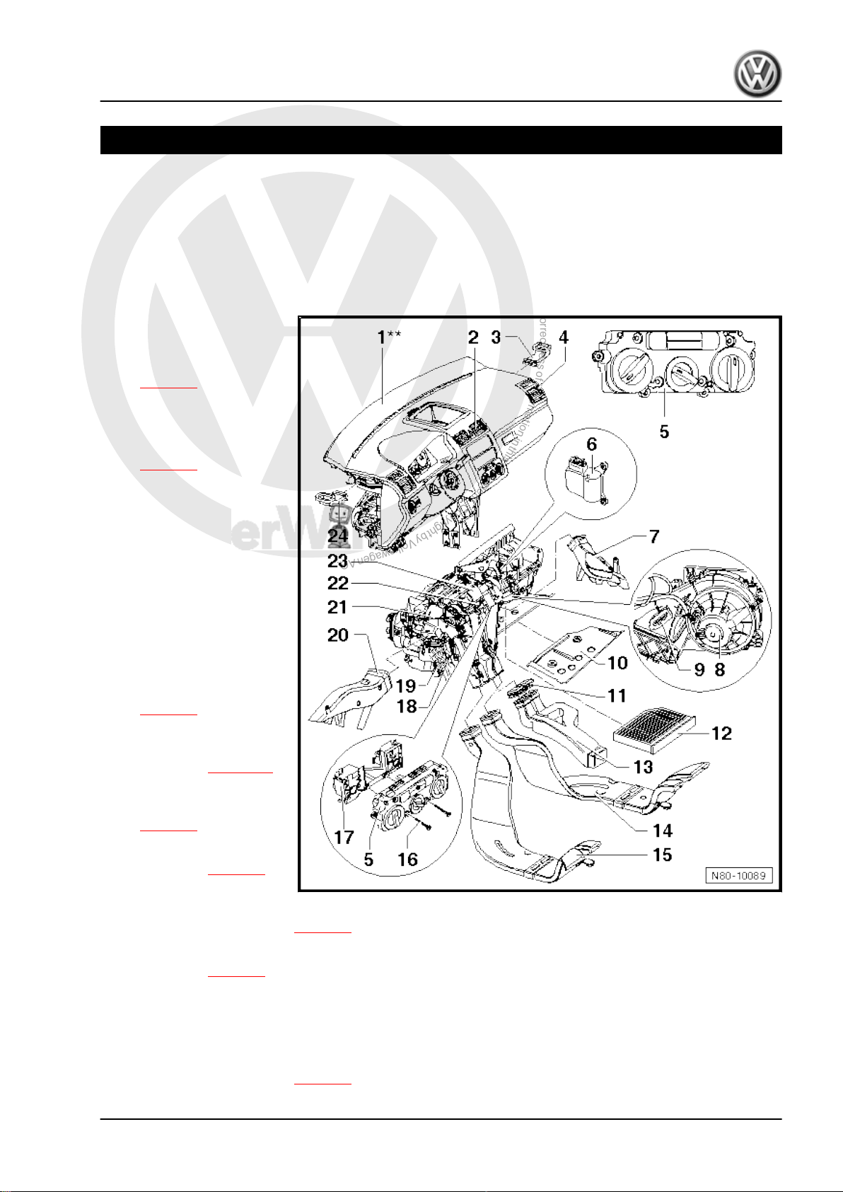
1.1 Passenger compartment heating
Disconnect battery before removing components marked ** ⇒
Rep. Gr. 27 .
1 - Dash panel**
2 - Centre vents
❑ Removing vent
3 - Right side vent
4 - Right vent
❑ Removing vent
5 - Controls for fresh and heat‐
ed air
❑ With fresh air and air re‐
⇒ page 5 .
⇒ page 5 .
circulation flap switch E159- .
❑ With heated driver seat
regulator -E94- and
heated front passenger
seat regulator -E95-
❑ For vehicles with sup‐
plementary heating hav‐
ing instant heating but‐
ton -E537- .
❑ Removing controls
⇒ page 7 .
6 - Fresh air and air recircula‐
tion flap control motor -V154-
❑ Removing ⇒ page 11
7 - Right footwell vent
❑ Removing and installing
⇒ page 7
8 - Fresh air blower -V2-
❑ Removing ⇒ page 3
9 - Fresh air blower series re‐
sistor with overheating fuse -N24-
❑ Removing and installing ⇒ page 3
Golf 2004 ➤
Heating, air conditioning - Edition 02.2008
10 - Baffle plate for heater unit
❑ Removing ⇒ page 2
11 - Sealing cap
❑ Fitted only in vehicles without air duct to vent in rear centre console.
12 - Dust and pollen filter
❑ With activated charcoal filter
❑ Removing and installing ⇒ page 4
1. Repairing heater 1
P
r
o
t
e
c
t
e
d
b
y
c
o
p
y
r
i
g
h
t
.
C
o
p
y
i
n
g
f
o
r
p
r
i
v
a
t
e
o
r
c
o
m
m
e
r
c
i
a
l
p
u
r
p
o
s
e
s
,
i
n
p
a
r
t
o
r
i
n
w
h
o
l
e
,
i
s
n
o
t
p
e
r
m
i
t
t
e
d
u
n
l
e
s
s
a
u
t
h
o
r
i
s
e
d
b
y
V
o
l
k
s
w
a
g
e
n
A
G
.
V
o
l
k
s
w
a
g
e
n
A
G
d
o
e
s
n
o
t
g
u
a
r
a
n
t
e
e
o
r
a
c
c
e
p
t
a
n
y
l
i
a
b
i
l
i
t
y
w
i
t
h
r
e
s
p
e
c
t
t
o
t
h
e
c
o
r
r
e
c
t
n
e
s
s
o
f
i
n
f
o
r
m
a
t
i
o
n
i
n
t
h
i
s
d
o
c
u
m
e
n
t
.
C
o
p
y
r
i
g
h
t
b
y
V
o
l
k
s
w
a
g
e
n
A
G
.
Golf 2004 ➤
Heating, air conditioning - Edition 02.2008
13 - Connecting piece
❑ For centre console air duct (to rear vents)
❑ To remove, centre console must be removed ⇒ Rep. Gr. 68 .
14 - Air duct for right rear footwell
❑ Removing and installing ⇒ page 6
15 - Air duct for left rear footwell
❑ Removing and installing ⇒ page 6
16 - Securing bolt
❑ Qty. 8
❑ Various lengths.
17 - Adapter for controls
❑ Removing and installing ⇒ page 7
18 - Auxiliary air heater element -Z35-
❑ With auxiliary air heater control unit -J604- .
❑ Checking: with vehicle diagnostic, testing and information system -VAS 5051- (or later model), under
Heating, ventilation, air conditioning; Systems capable of self-diagnosis; Auxiliary heating; Electrical
components.
❑ Installed only in vehicles with diesel engines without supplementary heater.
❑ Removing and installing ⇒ page 15
19 - Heat exchanger
❑ After renewing heat exchanger, renew coolant completely
❑ Removing and installing ⇒ page 12
20 - Left footwell vent
❑ Removing and installing ⇒ page 7
21 - Bowden cable for temperature flap
❑ Removing and installing ⇒ page 10
22 - Flexible shaft for air distribution
❑ Removing and installing ⇒ page 9
23 - Heater unit
❑ Removing and installing ⇒ page 19
❑ Dismantling and assembling ⇒ page 23
24 - Left side vent
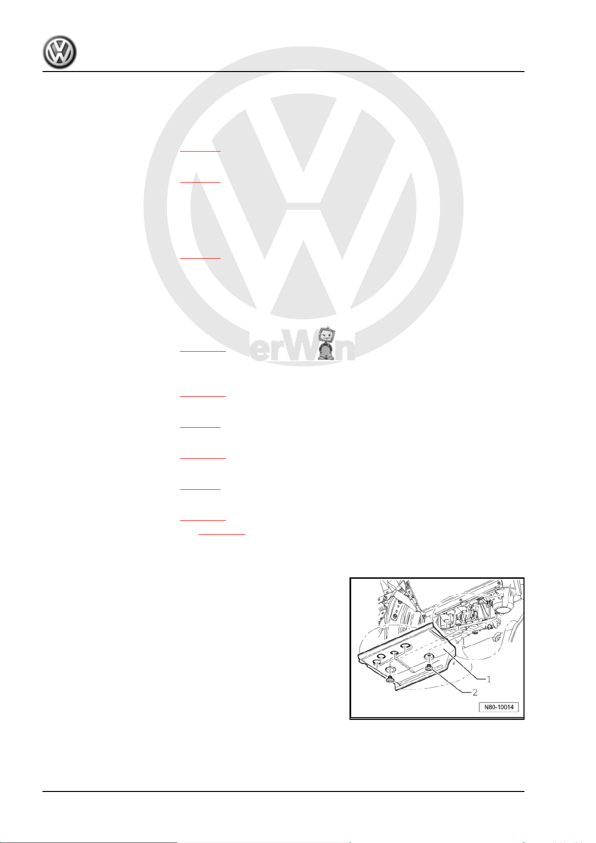
Removing heater unit baffle plate
– Remove plastic bolts -2- and remove baffle plate -1-.
2 Rep. Gr.80 - Heating
P
r
o
t
e
c
t
e
d
b
y
c
o
p
y
r
i
g
h
t
.
C
o
p
y
i
n
g
f
o
r
p
r
i
v
a
t
e
o
r
c
o
m
m
e
r
c
i
a
l
p
u
r
p
o
s
e
s
,
i
n
p
a
r
t
o
r
i
n
w
h
o
l
e
,
i
s
n
o
t
p
e
r
m
i
t
t
e
d
u
n
l
e
s
s
a
u
t
h
o
r
i
s
e
d
b
y
V
o
l
k
s
w
a
g
e
n
A
G
.
V
o
l
k
s
w
a
g
e
n
A
G
d
o
e
s
n
o
t
g
u
a
r
a
n
t
e
e
o
r
a
c
c
e
p
t
a
n
y
l
i
a
b
i
l
i
t
y
w
i
t
h
r
e
s
p
e
c
t
t
o
t
h
e
c
o
r
r
e
c
t
n
e
s
s
o
f
i
n
f
o
r
m
a
t
i
o
n
i
n
t
h
i
s
d
o
c
u
m
e
n
t
.
C
o
p
y
r
i
g
h
t
b
y
V
o
l
k
s
w
a
g
e
n
A
G
.
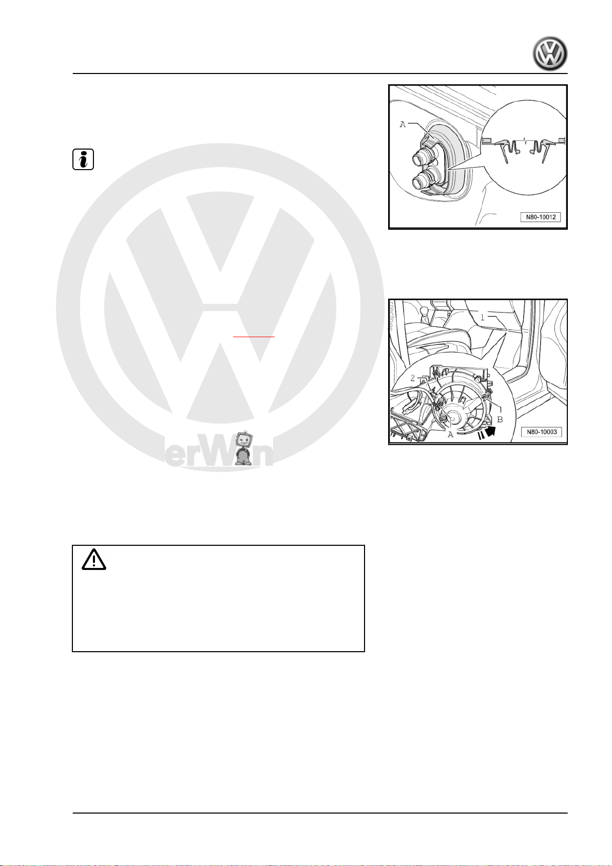
Installation position of seal between heater unit and engine com‐
partment
– First insert seal between heater unit and engine compartment
-A- in bulkhead and then attach to heat exchanger.
Note
To prevent water from entering vehicle interior, installation posi‐
tion must be observed.
1.2 Removing fresh air blower -V2-
1.2.1 Removing
Fresh air blower -V2- is accessible from footwell on front passen‐
ger side.
– Remove heater unit baffle plate ⇒ page 2 .
– Pull connector -A- off fresh air blower -V2- .
– Remove bolt -B- for fresh air blower -V2- (1 Nm).
– Release catch -2-, turn fresh air blower -V2- in direction of
-arrow- and remove.
1.3 Removing and installing fresh air blower
series resistor with overheating fuse N24-
Golf 2004 ➤
Heating, air conditioning - Edition 02.2008
1.3.1 Removing
WARNING
Danger of burn injuries.
The fresh air blower series resistor with overheating fuse -N24can be hot.
Before removing fresh air blower series resistor with overheat‐
ing fuse -N24- , let it cool off.
First carry out the following work:
1. Repairing heater 3
P
r
o
t
e
c
t
e
d
b
y
c
o
p
y
r
i
g
h
t
.
C
o
p
y
i
n
g
f
o
r
p
r
i
v
a
t
e
o
r
c
o
m
m
e
r
c
i
a
l
p
u
r
p
o
s
e
s
,
i
n
p
a
r
t
o
r
i
n
w
h
o
l
e
,
i
s
n
o
t
p
e
r
m
i
t
t
e
d
u
n
l
e
s
s
a
u
t
h
o
r
i
s
e
d
b
y
V
o
l
k
s
w
a
g
e
n
A
G
.
V
o
l
k
s
w
a
g
e
n
A
G
d
o
e
s
n
o
t
g
u
a
r
a
n
t
e
e
o
r
a
c
c
e
p
t
a
n
y
l
i
a
b
i
l
i
t
y
w
i
t
h
r
e
s
p
e
c
t
t
o
t
h
e
c
o
r
r
e
c
t
n
e
s
s
o
f
i
n
f
o
r
m
a
t
i
o
n
i
n
t
h
i
s
d
o
c
u
m
e
n
t
.
C
o
p
y
r
i
g
h
t
b
y
V
o
l
k
s
w
a
g
e
n
A
G
.
Golf 2004 ➤
Heating, air conditioning - Edition 02.2008
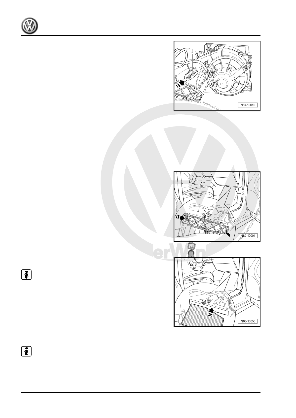
– Remove heater unit baffle plate ⇒ page 2 .
– Pull connector -1- off fresh air blower series resistor with over‐
heating fuse -N24- .
– Press catch in -direction of arrow- and remove fresh air blower
series resistor with overheating fuse -N24- from heater unit.
1.3.2 Installing
Install in reverse order.
1.4 Removing and installing dust and pollen filter
1.4.1 Removing
– Remove footwell trim -1- on front passenger side.
– Remove baffle plate -2- from heater unit ⇒ page 2 .
– Release cover -3- in direction of arrow.
– Remove dust and pollen filter from heater unit downwards.
1.4.2 Installing
Install in reverse order.
Note
Observe installation position of dust and pollen filter.
1.5 Removing vents
Note
Removal and installation of rear vents (in arm rest) is described
in ELSA under General body repairs, interior; ⇒ Rep. Gr. 68 ;
Removing and installing centre console (Highline version).
4 Rep. Gr.80 - Heating
P
r
o
t
e
c
t
e
d
b
y
c
o
p
y
r
i
g
h
t
.
C
o
p
y
i
n
g
f
o
r
p
r
i
v
a
t
e
o
r
c
o
m
m
e
r
c
i
a
l
p
u
r
p
o
s
e
s
,
i
n
p
a
r
t
o
r
i
n
w
h
o
l
e
,
i
s
n
o
t
p
e
r
m
i
t
t
e
d
u
n
l
e
s
s
a
u
t
h
o
r
i
s
e
d
b
y
V
o
l
k
s
w
a
g
e
n
A
G
.
V
o
l
k
s
w
a
g
e
n
A
G
d
o
e
s
n
o
t
g
u
a
r
a
n
t
e
e
o
r
a
c
c
e
p
t
a
n
y
l
i
a
b
i
l
i
t
y
w
i
t
h
r
e
s
p
e
c
t
t
o
t
h
e
c
o
r
r
e
c
t
n
e
s
s
o
f
i
n
f
o
r
m
a
t
i
o
n
i
n
t
h
i
s
d
o
c
u
m
e
n
t
.
C
o
p
y
r
i
g
h
t
b
y
V
o
l
k
s
w
a
g
e
n
A
G
.
1.5.1 Removing centre vents
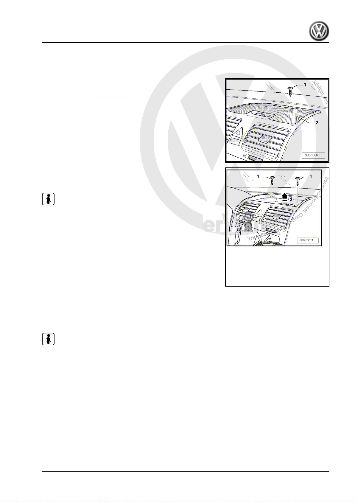
– On vehicles with a storage compartment in the centre vent
trim, the rubber mat must be removed to reach bolt -1-.
– On vehicles with Climatronic, first remove the sunlight pene‐
tration photosensor -G107- or the sunlight penetration photo‐
sensor 2 -G134- ⇒ page 59 .
– Remove bolt -1-.
– Remove cover -2- (only in vehicles with Climatronic).
– Remove securing bolts -1-.
Note
For vehicles with a storage compartment in dash panel, bolts are
beneath a trim mat.
– Remove compartment from dash panel.
Heating, air conditioning - Edition 02.2008
– Remove central vents -2- upwards -arrow-.
– Separate connectors from central vents.
Golf 2004 ➤
1.5.2 Installing
Install in reverse order.
1.5.3 Removing right or left vent
Note
♦
The procedure for removal of vents is identical on both sides.
♦
To avoid damage to dash panel, use a pad when levering out
components.
1. Repairing heater 5
P
r
o
t
e
c
t
e
d
b
y
c
o
p
y
r
i
g
h
t
.
C
o
p
y
i
n
g
f
o
r
p
r
i
v
a
t
e
o
r
c
o
m
m
e
r
c
i
a
l
p
u
r
p
o
s
e
s
,
i
n
p
a
r
t
o
r
i
n
w
h
o
l
e
,
i
s
n
o
t
p
e
r
m
i
t
t
e
d
u
n
l
e
s
s
a
u
t
h
o
r
i
s
e
d
b
y
V
o
l
k
s
w
a
g
e
n
A
G
.
V
o
l
k
s
w
a
g
e
n
A
G
d
o
e
s
n
o
t
g
u
a
r
a
n
t
e
e
o
r
a
c
c
e
p
t
a
n
y
l
i
a
b
i
l
i
t
y
w
i
t
h
r
e
s
p
e
c
t
t
o
t
h
e
c
o
r
r
e
c
t
n
e
s
s
o
f
i
n
f
o
r
m
a
t
i
o
n
i
n
t
h
i
s
d
o
c
u
m
e
n
t
.
C
o
p
y
r
i
g
h
t
b
y
V
o
l
k
s
w
a
g
e
n
A
G
.
Golf 2004 ➤
Heating, air conditioning - Edition 02.2008
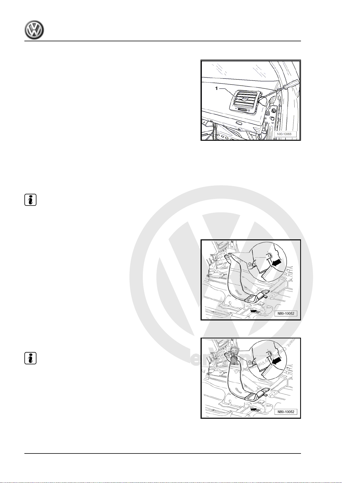
1.5.4 Removing
– Using an appropriate tool, lever out vent -1-.
– Separate connector from vent.
1.5.5 Installing
Install in reverse order.
1.5.6 Removing and installing right and left rear footwell air ducts
Note
The procedure for removal of footwell air ducts is identical on both
sides.
– Remove driver or front passenger seat ⇒ Rep. Gr. 72 .
– Remove centre console ⇒ Rep. Gr. 68 .
– Raise floor covering, unclip rear footwell air duct from under‐
body and pull off heater unit.
1.5.7 Installing
Install in reverse order.
Note
When installing rear footwell air duct, ensure that duct is first
pushed onto heater unit -arrow- and then clipped to underbody.
6 Rep. Gr.80 - Heating
P
r
o
t
e
c
t
e
d
b
y
c
o
p
y
r
i
g
h
t
.
C
o
p
y
i
n
g
f
o
r
p
r
i
v
a
t
e
o
r
c
o
m
m
e
r
c
i
a
l
p
u
r
p
o
s
e
s
,
i
n
p
a
r
t
o
r
i
n
w
h
o
l
e
,
i
s
n
o
t
p
e
r
m
i
t
t
e
d
u
n
l
e
s
s
a
u
t
h
o
r
i
s
e
d
b
y
V
o
l
k
s
w
a
g
e
n
A
G
.
V
o
l
k
s
w
a
g
e
n
A
G
d
o
e
s
n
o
t
g
u
a
r
a
n
t
e
e
o
r
a
c
c
e
p
t
a
n
y
l
i
a
b
i
l
i
t
y
w
i
t
h
r
e
s
p
e
c
t
t
o
t
h
e
c
o
r
r
e
c
t
n
e
s
s
o
f
i
n
f
o
r
m
a
t
i
o
n
i
n
t
h
i
s
d
o
c
u
m
e
n
t
.
C
o
p
y
r
i
g
h
t
b
y
V
o
l
k
s
w
a
g
e
n
A
G
.
1.5.8 Removing right footwell vent
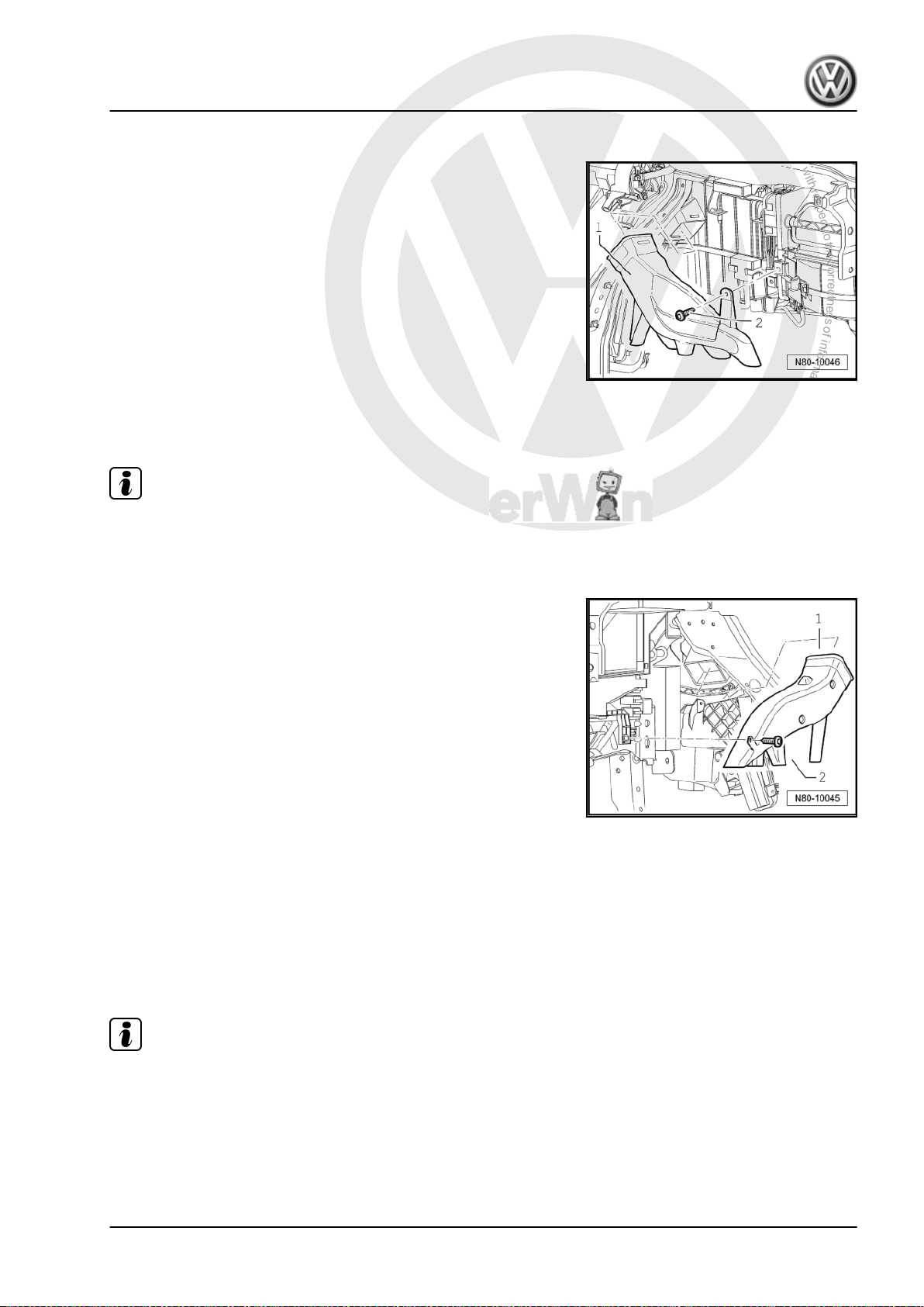
– Remove glove compartment ⇒ Rep. Gr. 68 .
– Remove securing bolt -2- (1.5 ± 0.2 Nm) and remove right
footwell vent -1-.
1.5.9 Installing
Install in reverse order.
Note
If vehicle has glove box cooling, ensure that refrigerant hose is
properly seated.
1.5.10 Removing left footwell vent
Heating, air conditioning - Edition 02.2008
– Remove driver side footwell cover ⇒ Rep. Gr. 68 .
– Remove securing bolt -2- (1.5 ± 0.2 Nm) and remove left foot‐
well vent -1-.
Golf 2004 ➤
1.5.11 Installing
Install in reverse order.
1.6 Removing and installing controls for heated and fresh air
1.6.1 Removing
Note
♦
The control consists of two separable housings. Before re‐
moving controls, set rotary knobs to the following positions:
♦
Heater control to “cold”
♦
Blower to “0”
♦
Vent direction to “footwell”
– Remove radio ⇒ Rep. Gr. 91 .
1. Repairing heater 7
P
r
o
t
e
c
t
e
d
b
y
c
o
p
y
r
i
g
h
t
.
C
o
p
y
i
n
g
f
o
r
p
r
i
v
a
t
e
o
r
c
o
m
m
e
r
c
i
a
l
p
u
r
p
o
s
e
s
,
i
n
p
a
r
t
o
r
i
n
w
h
o
l
e
,
i
s
n
o
t
p
e
r
m
i
t
t
e
d
u
n
l
e
s
s
a
u
t
h
o
r
i
s
e
d
b
y
V
o
l
k
s
w
a
g
e
n
A
G
.
V
o
l
k
s
w
a
g
e
n
A
G
d
o
e
s
n
o
t
g
u
a
r
a
n
t
e
e
o
r
a
c
c
e
p
t
a
n
y
l
i
a
b
i
l
i
t
y
w
i
t
h
r
e
s
p
e
c
t
t
o
t
h
e
c
o
r
r
e
c
t
n
e
s
s
o
f
i
n
f
o
r
m
a
t
i
o
n
i
n
t
h
i
s
d
o
c
u
m
e
n
t
.
C
o
p
y
r
i
g
h
t
b
y
V
o
l
k
s
w
a
g
e
n
A
G
.
Golf 2004 ➤
Heating, air conditioning - Edition 02.2008
– For vehicles without radio, remove centre dash panel trim ⇒
Rep. Gr. 68 .
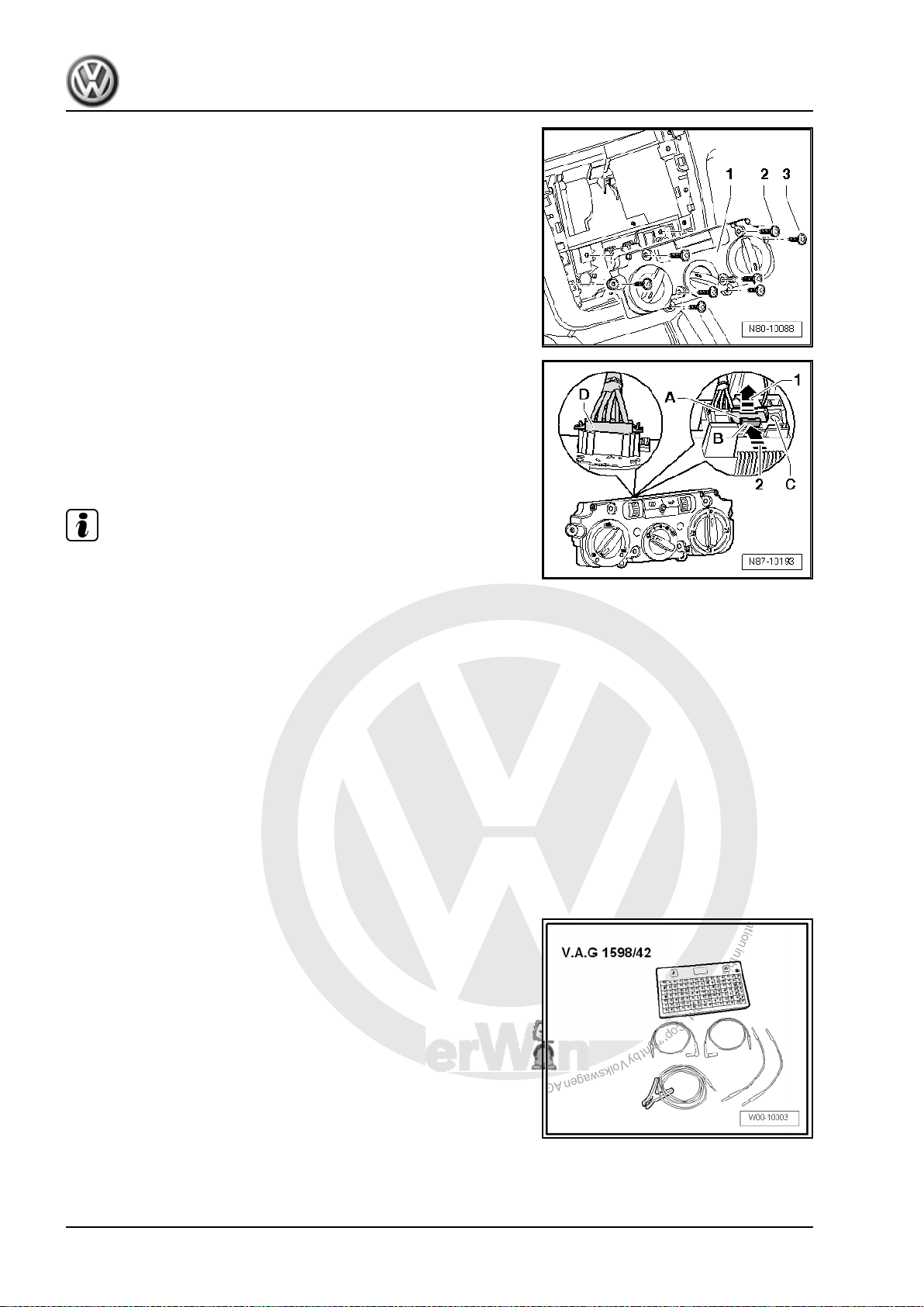
– Remove bolts -2- (4.2 x 45) and -3- (4.2 x 16) and remove the
controls -1- from centre console.
Specified torque for bolts -2- and -3- (1.5 ± 0.2 Nm).
– Release connector catch -A- by pulling in direction of arrow
-1-.
– Push connector catch -B- to connector -arrow 2- and remove
connector -C-.
– Release connector catch -D- and remove connector -D-.
Note
Figure shows “Climatic” version. The procedure for releasing con‐
nector is the same.
1.6.2 Installing
Installation is performed in the reverse order. Ensure that rotary
knobs are in the same positions as when removed.
1.7 Connectors on controls for heated and fresh air
1.7.1 Pin assignment for multi-pin connectors on back of controls for heated and fresh air
Special tools and workshop equipment required
♦ Test box -V.A.G 1598/42-
♦ Adapter cable -V.A.G 1598/47-
♦ Template -1598/47-2-
8 Rep. Gr.80 - Heating
P
r
o
t
e
c
t
e
d
b
y
c
o
p
y
r
i
g
h
t
.
C
o
p
y
i
n
g
f
o
r
p
r
i
v
a
t
e
o
r
c
o
m
m
e
r
c
i
a
l
p
u
r
p
o
s
e
s
,
i
n
p
a
r
t
o
r
i
n
w
h
o
l
e
,
i
s
n
o
t
p
e
r
m
i
t
t
e
d
u
n
l
e
s
s
a
u
t
h
o
r
i
s
e
d
b
y
V
o
l
k
s
w
a
g
e
n
A
G
.
V
o
l
k
s
w
a
g
e
n
A
G
d
o
e
s
n
o
t
g
u
a
r
a
n
t
e
e
o
r
a
c
c
e
p
t
a
n
y
l
i
a
b
i
l
i
t
y
w
i
t
h
r
e
s
p
e
c
t
t
o
t
h
e
c
o
r
r
e
c
t
n
e
s
s
o
f
i
n
f
o
r
m
a
t
i
o
n
i
n
t
h
i
s
d
o
c
u
m
e
n
t
.
C
o
p
y
r
i
g
h
t
b
y
V
o
l
k
s
w
a
g
e
n
A
G
.
Heating, air conditioning - Edition 02.2008
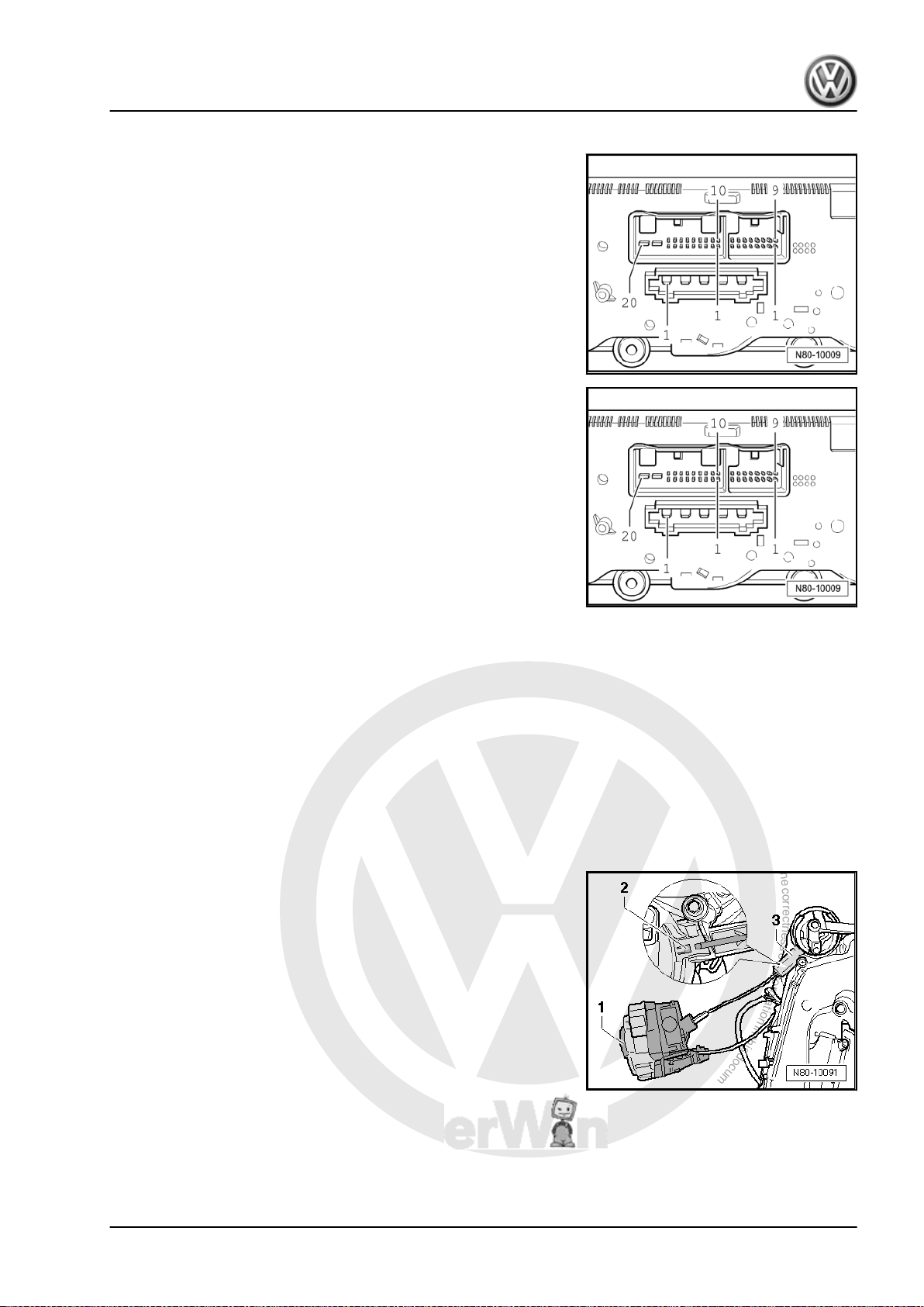
The 16-pin connector is vacant.
5-pin connector, T5 in current flow diagram
1 - 3rd blower speed
2 - 2nd blower speed
3 - 1st blower speed
4 - 4th blower speed
5 - X terminal
20-pin connector, T20c in current flow diagram
3 - Fresh air and air recirculation flap control motor -V154-
6 - Fresh air and air recirculation flap control motor -V154-
7 - With auxiliary air heater control unit -J604-
8 - Rear window
11 - Heated driver seat control unit -J131-
15 - Heated front passenger seat control unit -J132-
16 - Terminal 75, seat heating (optional)
18 - Terminal 30
19 - Terminal 15
20 - Terminal 31
1.8 Removing and installing flexible shaft for air distribution
1.8.1 Removing
– Remove radio ⇒ Rep. Gr. 91 .
– For vehicles without radio, remove centre dash panel trim ⇒
Rep. Gr. 68 .
– Remove glove compartment ⇒ Rep. Gr. 68 .
– Move flexible shaft to following position:
– Turn rotary switch for air distribution -1- until catch in shaft
-2- is visible in gears -3-.
Golf 2004 ➤
1. Repairing heater 9

P
r
o
t
e
c
t
e
d
b
y
c
o
p
y
r
i
g
h
t
.
C
o
p
y
i
n
g
f
o
r
p
r
i
v
a
t
e
o
r
c
o
m
m
e
r
c
i
a
l
p
u
r
p
o
s
e
s
,
i
n
p
a
r
t
o
r
i
n
w
h
o
l
e
,
i
s
n
o
t
p
e
r
m
i
t
t
e
d
u
n
l
e
s
s
a
u
t
h
o
r
i
s
e
d
b
y
V
o
l
k
s
w
a
g
e
n
A
G
.
V
o
l
k
s
w
a
g
e
n
A
G
d
o
e
s
n
o
t
g
u
a
r
a
n
t
e
e
o
r
a
c
c
e
p
t
a
n
y
l
i
a
b
i
l
i
t
y
w
i
t
h
r
e
s
p
e
c
t
t
o
t
h
e
c
o
r
r
e
c
t
n
e
s
s
o
f
i
n
f
o
r
m
a
t
i
o
n
i
n
t
h
i
s
d
o
c
u
m
e
n
t
.
C
o
p
y
r
i
g
h
t
b
y
V
o
l
k
s
w
a
g
e
n
A
G
.
Golf 2004 ➤
Heating, air conditioning - Edition 02.2008
– Remove controls for fresh and heated air ⇒ page 7 .
– Reach into centre console and release locking lug -1- by
pressing in direction of arrow.
– Pull flexible shaft out of adapter -2-.
Note
When flexible shaft is installed, the adapter and the rotary knobs
of the controls for heated and fresh air must be aligned in a spe‐
cific position to one another or the system will malfunction
⇒ page 10 .
1.8.2 Checking
Flexible shaft for air distribution flap actuator:
– Run fresh air blower at highest speed. If air flows out of de‐
froster jet in the “defrost” position and no air flows out of
footwell vent, then the flexible shaft is correctly installed. Oth‐
erwise, remove flexible shaft from adapter. Position controls
for heated and fresh air on adapter and turn rotary knob for air
distribution 1/2 turn (180°). Then reconnect flexible shaft. Re‐
peat check.
1.9 Removing and installing Bowden cable for temperature flap
1.9.1 Removing
– Remove controls for fresh and heated air ⇒ page 7 .
– Reach into centre console and release catch -1- of Bowden
cable sheath -2- and remove Bowden cable sheath from sup‐
port.
– Release ball on Bowden cable -3- from operating lever -4-.
10 Rep. Gr.80 - Heating
P
r
o
t
e
c
t
e
d
b
y
c
o
p
y
r
i
g
h
t
.
C
o
p
y
i
n
g
f
o
r
p
r
i
v
a
t
e
o
r
c
o
m
m
e
r
c
i
a
l
p
u
r
p
o
s
e
s
,
i
n
p
a
r
t
o
r
i
n
w
h
o
l
e
,
i
s
n
o
t
p
e
r
m
i
t
t
e
d
u
n
l
e
s
s
a
u
t
h
o
r
i
s
e
d
b
y
V
o
l
k
s
w
a
g
e
n
A
G
.
V
o
l
k
s
w
a
g
e
n
A
G
d
o
e
s
n
o
t
g
u
a
r
a
n
t
e
e
o
r
a
c
c
e
p
t
a
n
y
l
i
a
b
i
l
i
t
y
w
i
t
h
r
e
s
p
e
c
t
t
o
t
h
e
c
o
r
r
e
c
t
n
e
s
s
o
f
i
n
f
o
r
m
a
t
i
o
n
i
n
t
h
i
s
d
o
c
u
m
e
n
t
.
C
o
p
y
r
i
g
h
t
b
y
V
o
l
k
s
w
a
g
e
n
A
G
.
Heating, air conditioning - Edition 02.2008
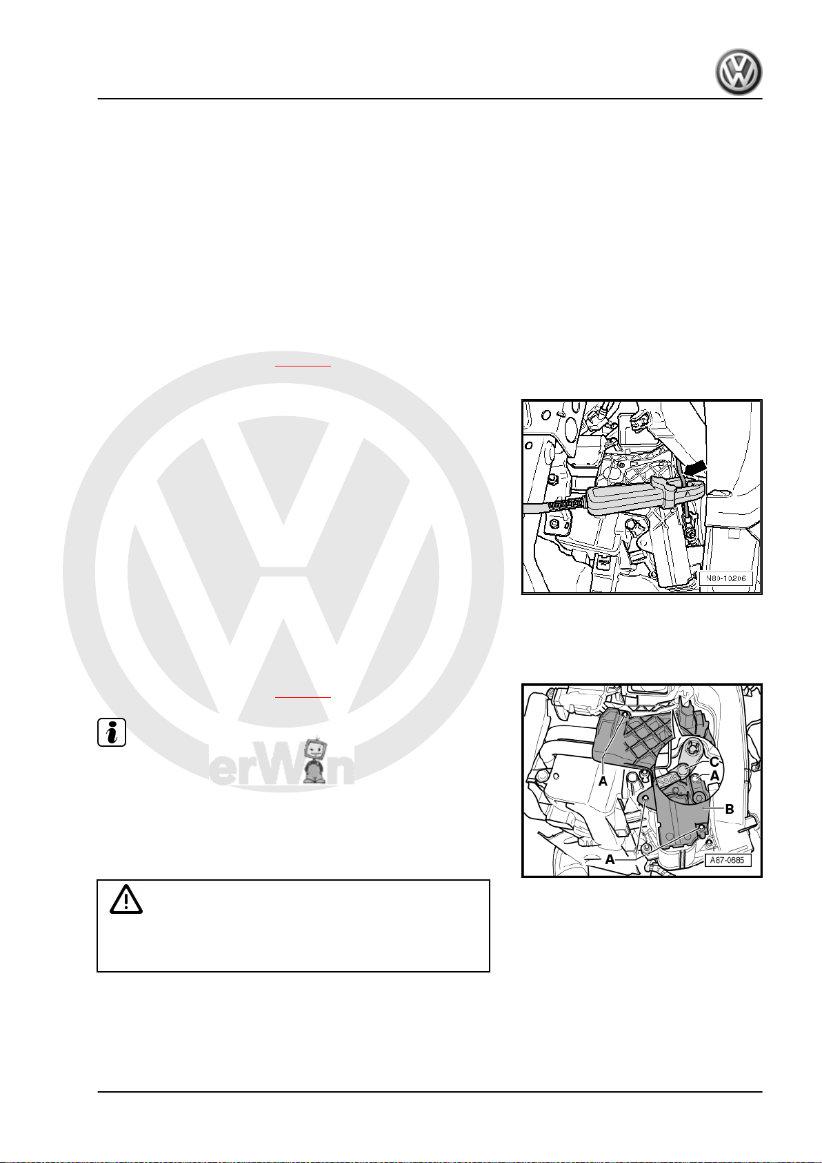
– Remove driver side footwell trim ⇒ Rep. Gr. 68 .
– Unclip Bowden cable from control unit for temperature flap
-A- and heater unit -B-.
1.9.2 Installing
Install in reverse order. Ensure that Bowden cable lies under hook
-arrow-.
– Check whether temperature knob can be easily turned from
“cold” to “warm”.
1.10 Removing and installing fresh air and air
1.10.1 Removing
Note
The position of the air recirculation flap must not be changed.
– Remove glove compartment ⇒ Rep. Gr. 68 .
– Remove cover -1-.
– Separate connector from fresh air and air recirculation flap
control motor -V154- -2-.
– Remove fresh air and air recirculation flap control motor -
V154- -2- from mountings.
recirculation flap control motor -V154-
Golf 2004 ➤
1.10.2 Installing
Install in reverse order.
1. Repairing heater 11
P
r
o
t
e
c
t
e
d
b
y
c
o
p
y
r
i
g
h
t
.
C
o
p
y
i
n
g
f
o
r
p
r
i
v
a
t
e
o
r
c
o
m
m
e
r
c
i
a
l
p
u
r
p
o
s
e
s
,
i
n
p
a
r
t
o
r
i
n
w
h
o
l
e
,
i
s
n
o
t
p
e
r
m
i
t
t
e
d
u
n
l
e
s
s
a
u
t
h
o
r
i
s
e
d
b
y
V
o
l
k
s
w
a
g
e
n
A
G
.
V
o
l
k
s
w
a
g
e
n
A
G
d
o
e
s
n
o
t
g
u
a
r
a
n
t
e
e
o
r
a
c
c
e
p
t
a
n
y
l
i
a
b
i
l
i
t
y
w
i
t
h
r
e
s
p
e
c
t
t
o
t
h
e
c
o
r
r
e
c
t
n
e
s
s
o
f
i
n
f
o
r
m
a
t
i
o
n
i
n
t
h
i
s
d
o
c
u
m
e
n
t
.
C
o
p
y
r
i
g
h
t
b
y
V
o
l
k
s
w
a
g
e
n
A
G
.
Golf 2004 ➤
Heating, air conditioning - Edition 02.2008
Note
After installing fresh air and air recirculation flap control motor V154- , check operation of air recirculation flap.
– Checking: vehicle diagnosis, testing and information system -
VAS 5051- or successor models.
– Renewing: initiate basic setting using vehicle diagnosis, test‐
ing and information system -VAS 5051- or successor models
⇒ page 42 .
1.11 Removing and installing heat exchanger
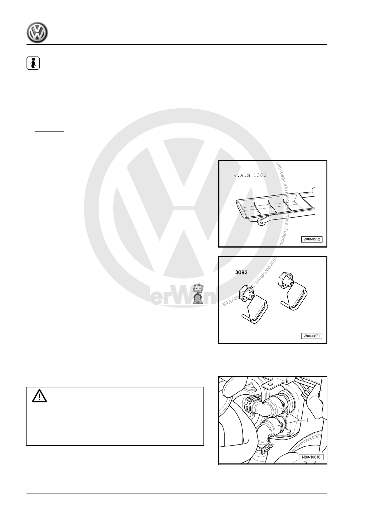
Special tools and workshop equipment required
♦ Drip tray -V.A.G 1306-
♦ Hose clamps up to 40 mm Ø -VAS 3093-
♦ Compressed air gun, commercially available
1.11.1 Removing
– Place drip tray -V.A.G 1306- beneath engine.
WARNING
Danger of scalding injuries.
When the engine is warm, the coolant temperature may be
above 100 °C. The cooling system is pressurised.
If necessary, release pressure before carrying out repairs.
12 Rep. Gr.80 - Heating
P
r
o
t
e
c
t
e
d
b
y
c
o
p
y
r
i
g
h
t
.
C
o
p
y
i
n
g
f
o
r
p
r
i
v
a
t
e
o
r
c
o
m
m
e
r
c
i
a
l
p
u
r
p
o
s
e
s
,
i
n
p
a
r
t
o
r
i
n
w
h
o
l
e
,
i
s
n
o
t
p
e
r
m
i
t
t
e
d
u
n
l
e
s
s
a
u
t
h
o
r
i
s
e
d
b
y
V
o
l
k
s
w
a
g
e
n
A
G
.
V
o
l
k
s
w
a
g
e
n
A
G
d
o
e
s
n
o
t
g
u
a
r
a
n
t
e
e
o
r
a
c
c
e
p
t
a
n
y
l
i
a
b
i
l
i
t
y
w
i
t
h
r
e
s
p
e
c
t
t
o
t
h
e
c
o
r
r
e
c
t
n
e
s
s
o
f
i
n
f
o
r
m
a
t
i
o
n
i
n
t
h
i
s
d
o
c
u
m
e
n
t
.
C
o
p
y
r
i
g
h
t
b
y
V
o
l
k
s
w
a
g
e
n
A
G
.
Heating, air conditioning - Edition 02.2008
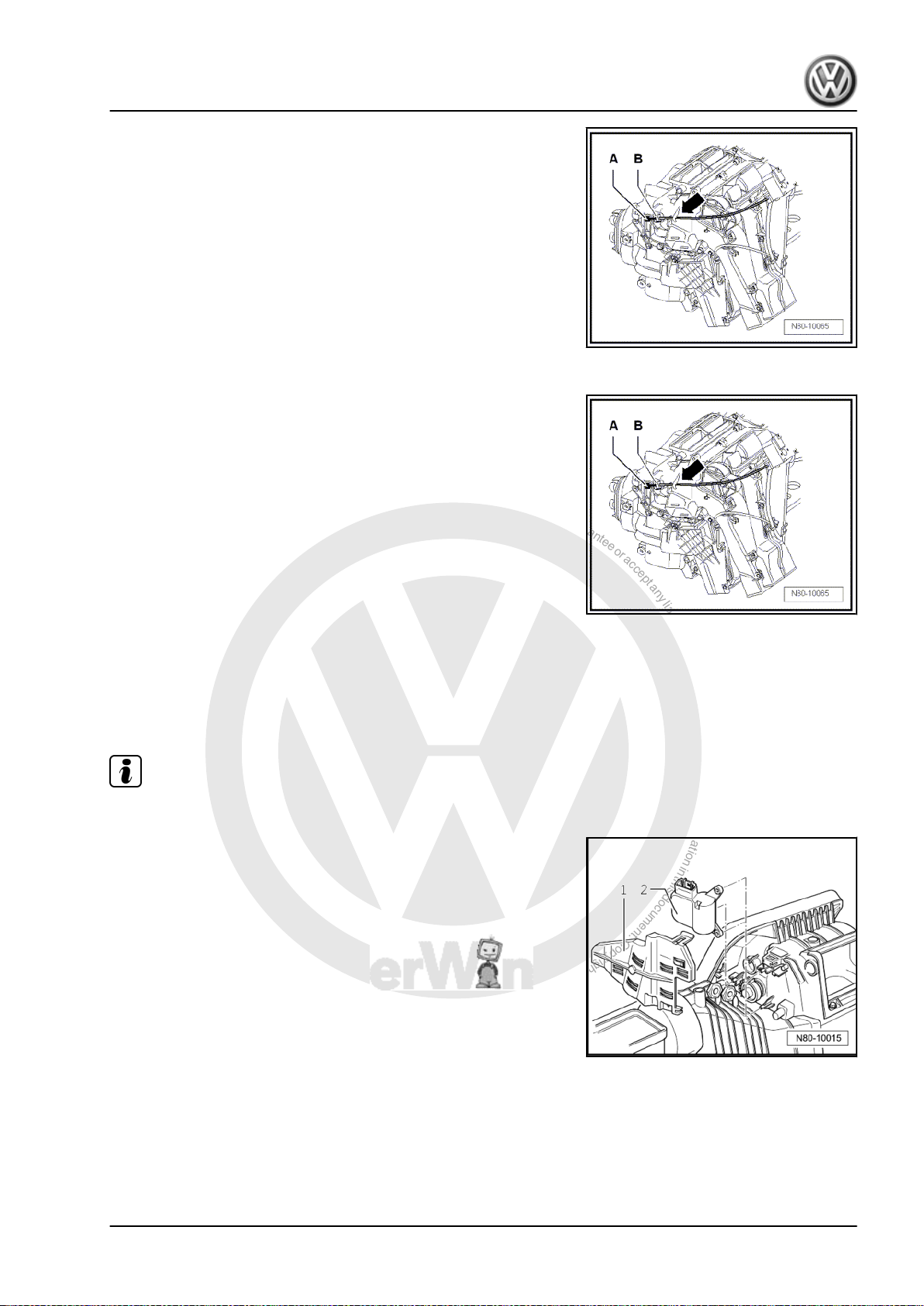
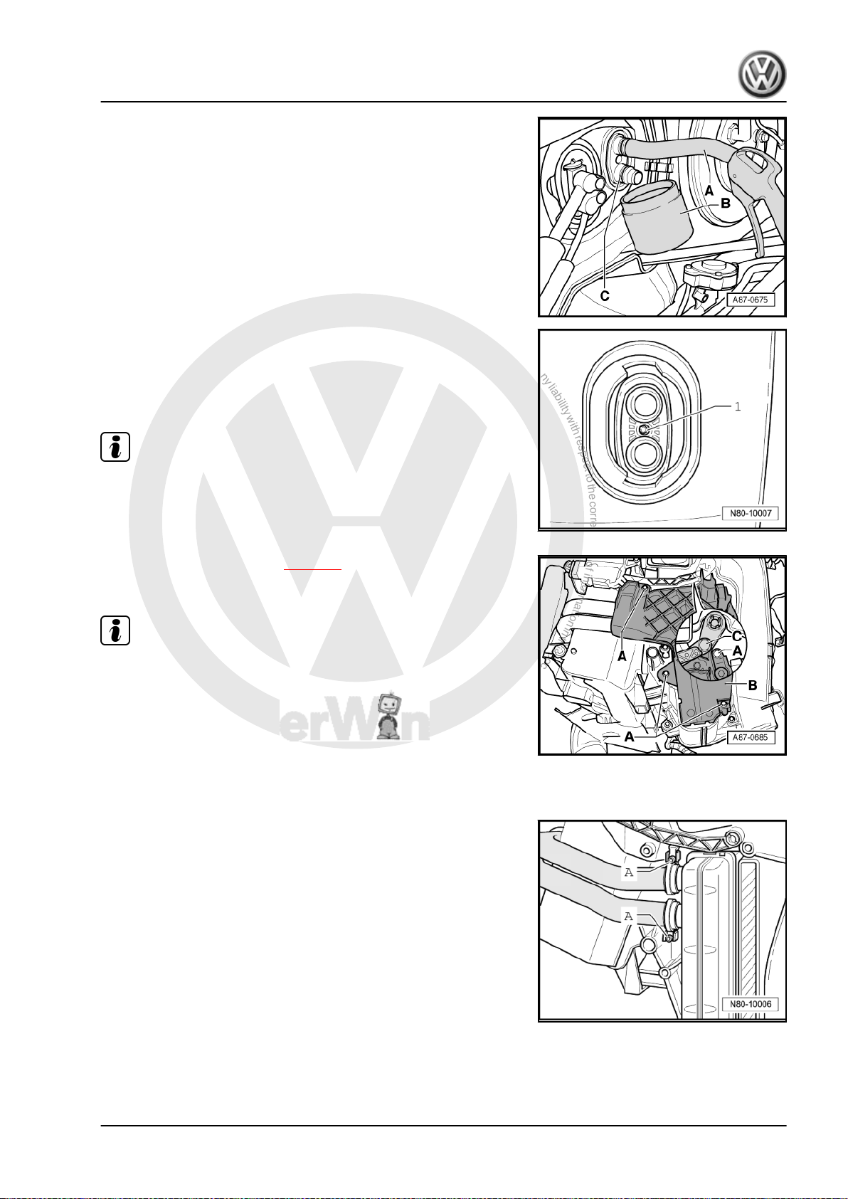
– Clamp off coolant hoses -1- using hose clamps up to 40 mm Ø
-VAS 3093- and disconnect coolant hoses to heat exchanger.
– Push a piece of hose -A- onto upper connection of heat ex‐
changer.
– Hold a container -B- under lower connection -C-.
– Using a compressed air pistol, carefully blow coolant out of
heat exchanger into container -B-.
Depending on the engine type, some parts must be removed ad‐
ditionally, e.g. the charge air pipe.
– Loosen bolt (6 mm hexagon socket head) -1- on flange be‐
tween heat exchanger connections, but do not remove com‐
pletely.
Loosening the bolt -1- loosens the coolant pipe which eases the
removal of the heat exchanger.
– Remove driver side footwell trim ⇒ Rep. Gr. 68 .
– Remove left footwell vent ⇒ page 7 .
– Remove bolts -A- and remove cover -B-.
♦
There are two different versions of cover -B-.
♦
The figure shows the version with auxiliary air heater element
Note
Note
-Z35- .
♦
If the lever -C- to temperature flap is positioned so the the up‐
per bolt -A- is not accessible. Change the position of the
temperature flap at the heater and fresh air controls. On vehi‐
cles with Climatronic, at the control and display unit (e.g. the
setting “Hi”).
Golf 2004 ➤
– Cover carpet in area under heat exchanger with waterproof foil
and water absorbing paper.
– Open pipe clamps -A- and pull coolant pipes out of heat ex‐
changer.
– Remove heat exchanger from heater unit.
1. Repairing heater 13
P
r
o
t
e
c
t
e
d
b
y
c
o
p
y
r
i
g
h
t
.
C
o
p
y
i
n
g
f
o
r
p
r
i
v
a
t
e
o
r
c
o
m
m
e
r
c
i
a
l
p
u
r
p
o
s
e
s
,
i
n
p
a
r
t
o
r
i
n
w
h
o
l
e
,
i
s
n
o
t
p
e
r
m
i
t
t
e
d
u
n
l
e
s
s
a
u
t
h
o
r
i
s
e
d
b
y
V
o
l
k
s
w
a
g
e
n
A
G
.
V
o
l
k
s
w
a
g
e
n
A
G
d
o
e
s
n
o
t
g
u
a
r
a
n
t
e
e
o
r
a
c
c
e
p
t
a
n
y
l
i
a
b
i
l
i
t
y
w
i
t
h
r
e
s
p
e
c
t
t
o
t
h
e
c
o
r
r
e
c
t
n
e
s
s
o
f
i
n
f
o
r
m
a
t
i
o
n
i
n
t
h
i
s
d
o
c
u
m
e
n
t
.
C
o
p
y
r
i
g
h
t
b
y
V
o
l
k
s
w
a
g
e
n
A
G
.
Golf 2004 ➤
Heating, air conditioning - Edition 02.2008
1.11.2 Installing
Installation is carried out in the reverse order. When installing,
note the following:
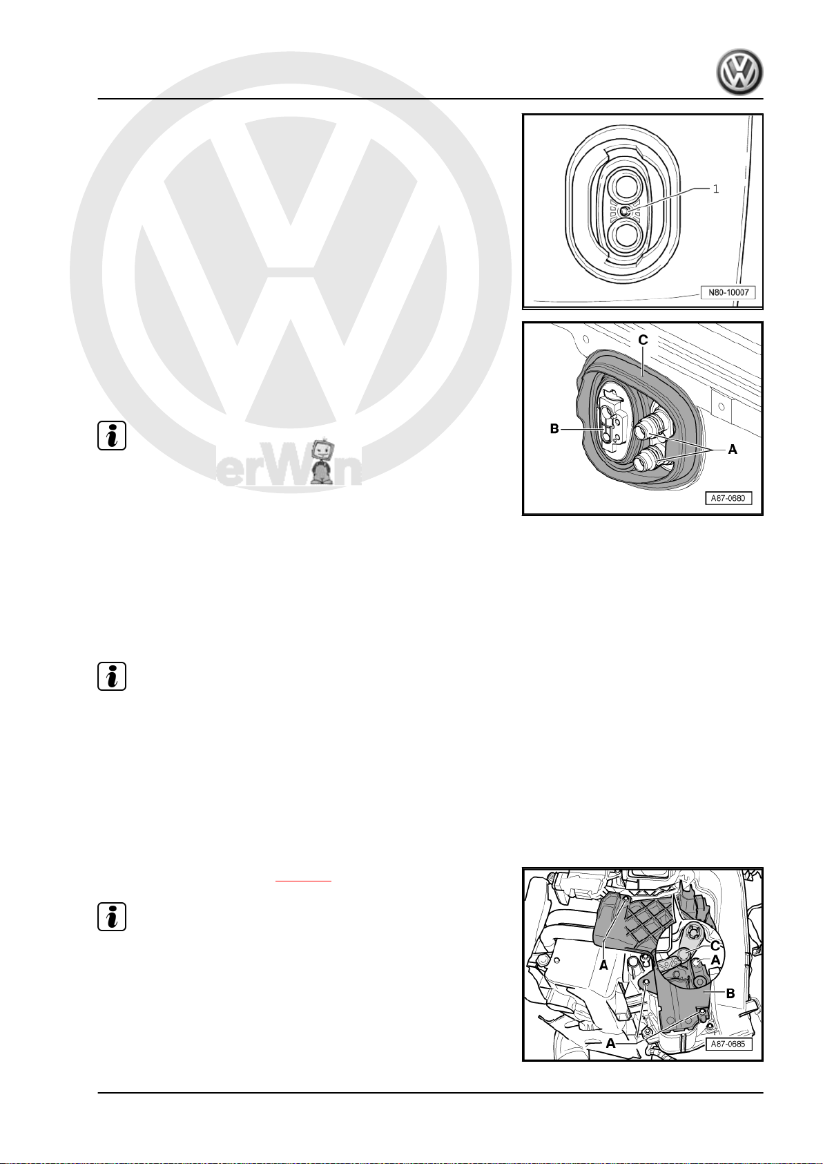
– Check seals attached to heat exchanger -A- and -B-. Install
heat exchanger only with undamaged seals.
Note
♦
An improperly bonded seal can roll up when heat exchanger
is pushed into heater unit.
♦
If seal is damaged or improperly attached, cold air can flow
past heat exchanger.
– Check heater unit for cleanliness through shaft -A- for heat
exchanger while heat exchanger is removed.
– If necessary, remove dirt or residue of leaked coolant from
heater unit, e.g. after removing a leaking heat exchanger.
– Push heat exchanger into heater unit.
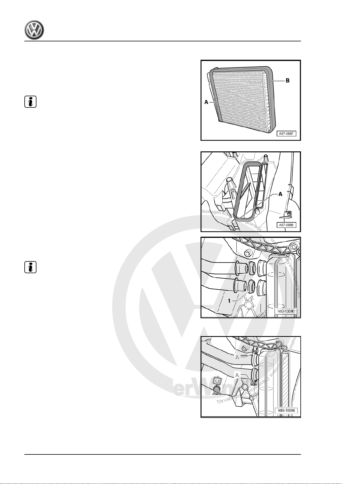
– Moisten seals -1- with coolant before installing.
– Set seals -1- in connection of heat exchanger.
Note
♦
Ensure that seals are installed in the proper direction as shown
in figure.
♦
Renew deformed pipe clamps.
– Connect coolant pipes to heat exchanger.
– During assembly, pipe clamps -A- must turn easily on coolant
pipes.
– Pipe clamps -A- must be installed as shown in figure.
– Tighten pipe clamps -A- to 2 Nm.
14 Rep. Gr.80 - Heating
P
r
o
t
e
c
t
e
d
b
y
c
o
p
y
r
i
g
h
t
.
C
o
p
y
i
n
g
f
o
r
p
r
i
v
a
t
e
o
r
c
o
m
m
e
r
c
i
a
l
p
u
r
p
o
s
e
s
,
i
n
p
a
r
t
o
r
i
n
w
h
o
l
e
,
i
s
n
o
t
p
e
r
m
i
t
t
e
d
u
n
l
e
s
s
a
u
t
h
o
r
i
s
e
d
b
y
V
o
l
k
s
w
a
g
e
n
A
G
.
V
o
l
k
s
w
a
g
e
n
A
G
d
o
e
s
n
o
t
g
u
a
r
a
n
t
e
e
o
r
a
c
c
e
p
t
a
n
y
l
i
a
b
i
l
i
t
y
w
i
t
h
r
e
s
p
e
c
t
t
o
t
h
e
c
o
r
r
e
c
t
n
e
s
s
o
f
i
n
f
o
r
m
a
t
i
o
n
i
n
t
h
i
s
d
o
c
u
m
e
n
t
.
C
o
p
y
r
i
g
h
t
b
y
V
o
l
k
s
w
a
g
e
n
A
G
.
– Check seating of both clamps -A- after tightening bolts. They
– Tighten bolt -1- on connecting flange between heat exchanger
– Check that grommet -C- in bulkhead is properly seated.
– If necessary, seal flanges for coolant pipes to heat exchanger
♦
♦
♦
must fully enclose the flange on the heat exchanger and the
coolant pipe and the must not contact other components.
connections to 2 Nm.
-A- and for expansion valve to evaporator (only in vehicles with
air conditioning) -B- at apertures in grommet -C- with silicone
adhesive sealant against moisture intrusion.
Note
Always renew seals.
After renewing heat exchanger, renew coolant completely ⇒
Rep. Gr. 19 .
Check coolant circuit for leaks. Examine in particular connec‐
tions between coolant pipes and heat exchanger.
Heating, air conditioning - Edition 02.2008
Golf 2004 ➤
1.12 Removing and installing auxiliary air heater element -Z35- on vehicles up to 1K-7P015628 and 1K-7B084800
Note
♦
Installed only in vehicles with diesel engines without supple‐
mentary heater.
♦
Checking: with vehicle diagnosis, testing and information sys‐
tem -VAS 5051- (or later model), under Heating, ventilation,
air conditioning; Systems capable of self-diagnosis; Auxiliary
heating; Electrical components.
1.12.1 Removing
– Remove driver side footwell trim ⇒ Rep. Gr. 68 .
– Remove left footwell vent ⇒ page 7 .
Note
If the lever -C- to temperature flap is positioned so the the upper
bolt -A- is not accessible. Change the position of the temperature
flap at the heater and fresh air controls. On vehicles with Clima‐
tronic, at the control and display unit (e.g. the setting “Hi”).
1. Repairing heater 15
P
r
o
t
e
c
t
e
d
b
y
c
o
p
y
r
i
g
h
t
.
C
o
p
y
i
n
g
f
o
r
p
r
i
v
a
t
e
o
r
c
o
m
m
e
r
c
i
a
l
p
u
r
p
o
s
e
s
,
i
n
p
a
r
t
o
r
i
n
w
h
o
l
e
,
i
s
n
o
t
p
e
r
m
i
t
t
e
d
u
n
l
e
s
s
a
u
t
h
o
r
i
s
e
d
b
y
V
o
l
k
s
w
a
g
e
n
A
G
.
V
o
l
k
s
w
a
g
e
n
A
G
d
o
e
s
n
o
t
g
u
a
r
a
n
t
e
e
o
r
a
c
c
e
p
t
a
n
y
l
i
a
b
i
l
i
t
y
w
i
t
h
r
e
s
p
e
c
t
t
o
t
h
e
c
o
r
r
e
c
t
n
e
s
s
o
f
i
n
f
o
r
m
a
t
i
o
n
i
n
t
h
i
s
d
o
c
u
m
e
n
t
.
C
o
p
y
r
i
g
h
t
b
y
V
o
l
k
s
w
a
g
e
n
A
G
.
Golf 2004 ➤
Heating, air conditioning - Edition 02.2008
– Disconnect the battery ⇒ Rep. Gr. 27 .
– Remove bolts -1- from cover -2-.
Caution
Danger of short circuit.
Disconnect battery before performing repair work.
– Remove securing nut for voltage supply -3- and earth con‐
nection -4- (6 ± 1 Nm).
– Pull connectors -5- off auxiliary air heater element -Z35- .
WARNING
Danger of burn injuries.
The auxiliary air heater element -Z35- may be hot.
Before removing auxiliary air heater element -Z35- , allow it to
cool off.
– Pull auxiliary air heater element -Z35- out of heater unit.
1.12.2 Installing
Install in reverse order.
1.13 Removing and installing auxiliary air heater element -Z35- on vehicles from 1K-7P015629 und 1K-7B084801
1.13.1 Checking auxiliary air heater element Z35- with peripherals
Auxiliary air heater element -Z35- peripherals (load signal for al‐
ternator terminal DF, low heat output relay -J359- , high heat
output relay -J360- , intake manifold temperature sender -G72- ,
coolant temperature sender -G62- ) can be read via the engine
control unit self-diagnosis.
1.13.2 Checking auxiliary air heater element Z35-
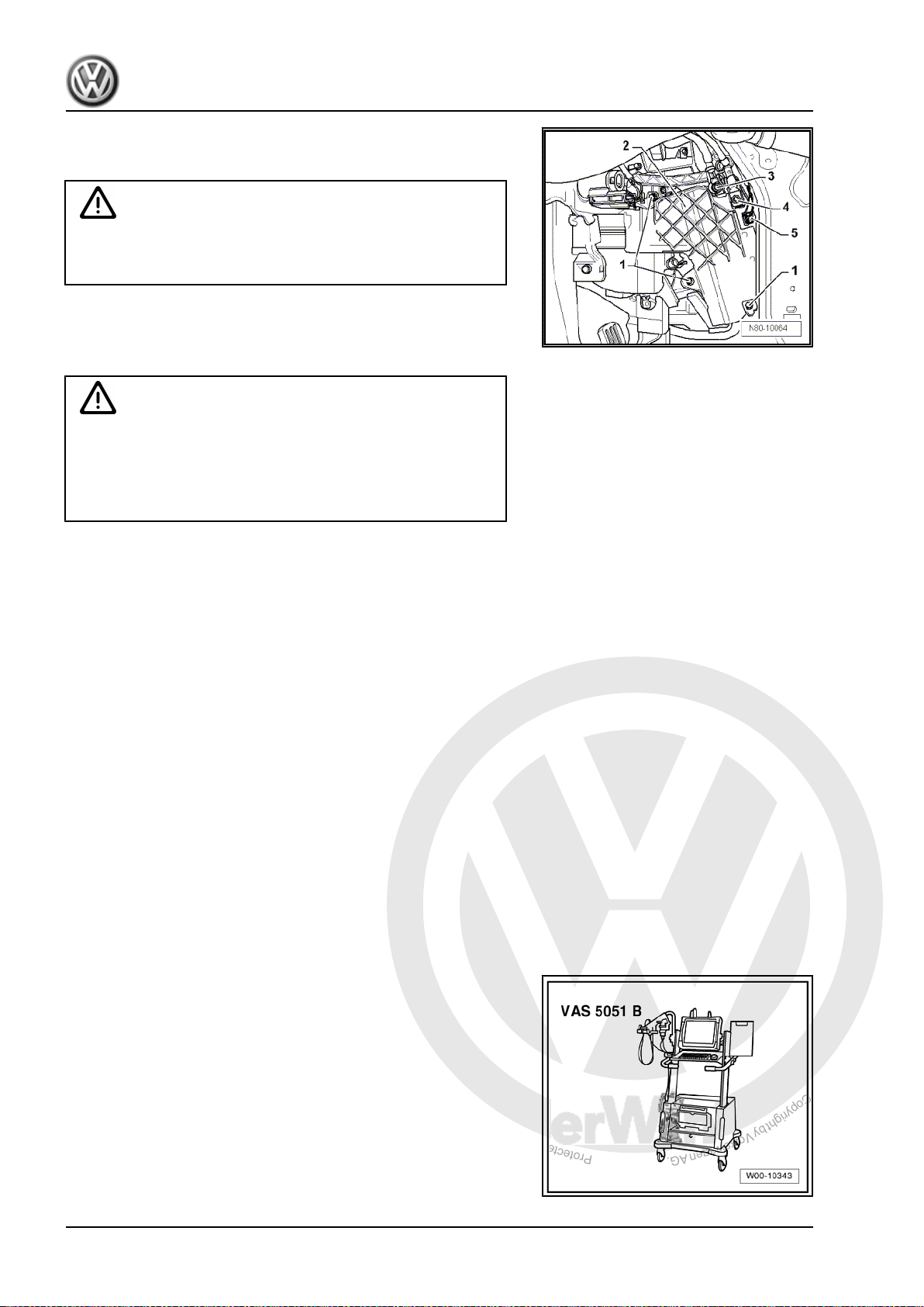
Special tools and workshop equipment required
♦ Vehicle diagnostic, testing and information system -VAS
5051B- with 100 A pick-up clamp -VAS 5051B/7-
16 Rep. Gr.80 - Heating
P
r
o
t
e
c
t
e
d
b
y
c
o
p
y
r
i
g
h
t
.
C
o
p
y
i
n
g
f
o
r
p
r
i
v
a
t
e
o
r
c
o
m
m
e
r
c
i
a
l
p
u
r
p
o
s
e
s
,
i
n
p
a
r
t
o
r
i
n
w
h
o
l
e
,
i
s
n
o
t
p
e
r
m
i
t
t
e
d
u
n
l
e
s
s
a
u
t
h
o
r
i
s
e
d
b
y
V
o
l
k
s
w
a
g
e
n
A
G
.
V
o
l
k
s
w
a
g
e
n
A
G
d
o
e
s
n
o
t
g
u
a
r
a
n
t
e
e
o
r
a
c
c
e
p
t
a
n
y
l
i
a
b
i
l
i
t
y
w
i
t
h
r
e
s
p
e
c
t
t
o
t
h
e
c
o
r
r
e
c
t
n
e
s
s
o
f
i
n
f
o
r
m
a
t
i
o
n
i
n
t
h
i
s
d
o
c
u
m
e
n
t
.
C
o
p
y
r
i
g
h
t
b
y
V
o
l
k
s
w
a
g
e
n
A
G
.
Heating, air conditioning - Edition 02.2008
1.13.3 Test conditions
• Intake temperature less than 19° C
• Coolant temperature less than 80° C
• Passenger compartment temperature about 20° C
• Battery voltage greater than 11 V
• Alternator load not greater than 50% (terminal DF)
• Engine speed greater than 450 rpm
• Turn rotary knob for interior temperature to end position for
maximum temperature.
Golf 2004 ➤
1.13.4 Test procedure
– Remove left footwell vent ⇒ page 7 .
– Remove centre console trim from left footwell.
– Measure current consumption on earth wire -arrow- using ve‐
Low heating output: approx. 30 amps
Medium heating output: approx. 60 amps
High heating output: approx. 80 amps
1.13.5 Removing and installing
Removing
– Remove driver side footwell trim ⇒ Rep. Gr. 68 .
– Remove left footwell vent ⇒ page 7 .
hicle diagnostic, testing and information system -VAS 5051Band 100 A pick-up clamp -VAS 5051B/7- .
Note
If the lever -C- to temperature flap is positioned so the the upper
bolt -A- is not accessible. Change the position of the temperature
flap at the heater and fresh air controls. On vehicles with Clima‐
tronic, at the control and display unit (e.g. the setting “Hi”).
– Disconnect the battery ⇒ Rep. Gr. 27 .
– Remove bolts -A- from cover -B-.
Caution
Danger of short circuit.
Disconnect battery before performing repair work.
1. Repairing heater 17
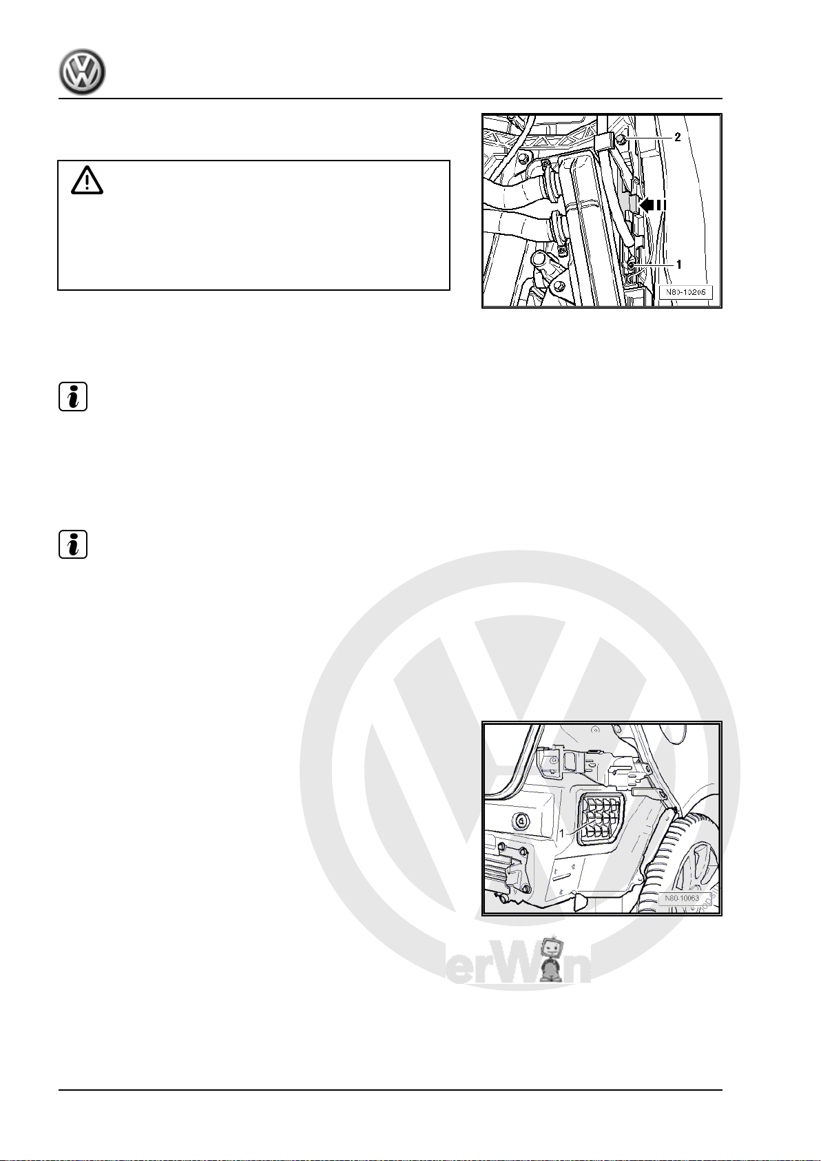
P
r
o
t
e
c
t
e
d
b
y
c
o
p
y
r
i
g
h
t
.
C
o
p
y
i
n
g
f
o
r
p
r
i
v
a
t
e
o
r
c
o
m
m
e
r
c
i
a
l
p
u
r
p
o
s
e
s
,
i
n
p
a
r
t
o
r
i
n
w
h
o
l
e
,
i
s
n
o
t
p
e
r
m
i
t
t
e
d
u
n
l
e
s
s
a
u
t
h
o
r
i
s
e
d
b
y
V
o
l
k
s
w
a
g
e
n
A
G
.
V
o
l
k
s
w
a
g
e
n
A
G
d
o
e
s
n
o
t
g
u
a
r
a
n
t
e
e
o
r
a
c
c
e
p
t
a
n
y
l
i
a
b
i
l
i
t
y
w
i
t
h
r
e
s
p
e
c
t
t
o
t
h
e
c
o
r
r
e
c
t
n
e
s
s
o
f
i
n
f
o
r
m
a
t
i
o
n
i
n
t
h
i
s
d
o
c
u
m
e
n
t
.
C
o
p
y
r
i
g
h
t
b
y
V
o
l
k
s
w
a
g
e
n
A
G
.
Golf 2004 ➤
Heating, air conditioning - Edition 02.2008
– Unscrew nut -1- (9 ± 1 Nm).
– Release connector strip catch -arrow-.
WARNING
Danger of burn injuries.
The auxiliary air heater element -Z35- may be hot.
Before removing auxiliary air heater element -Z35- , allow it to
cool off.
– Remove screw -2- (1.4 Nm) and pull out auxiliary air heater
element -Z35- from blower box.
Installing
Note
Ensure that the earth wire is in proper position.
Install in reverse order.
1.14 Checking ventilation
Note
♦
The stale air escapes via ventilation openings in the luggage
compartment trim.
♦
If the ventilation is to function properly, the ventilation open‐
ings must not be covered.
♦
The ventilation frames are located in the rear side panels be‐
hind the bumper.
1.14.1 Checking
– Remove rear bumper ⇒ Rep. Gr. 63 .
– Sealing lips -1- in ventilation frames on both sides of vehicle
must be free to move and close by themselves.
– Note installation position.
1.15 Removing and installing air intake screen
1.15.1 Removing
– Remove plenum chamber cover ⇒ Rep. Gr. 64 .
18 Rep. Gr.80 - Heating
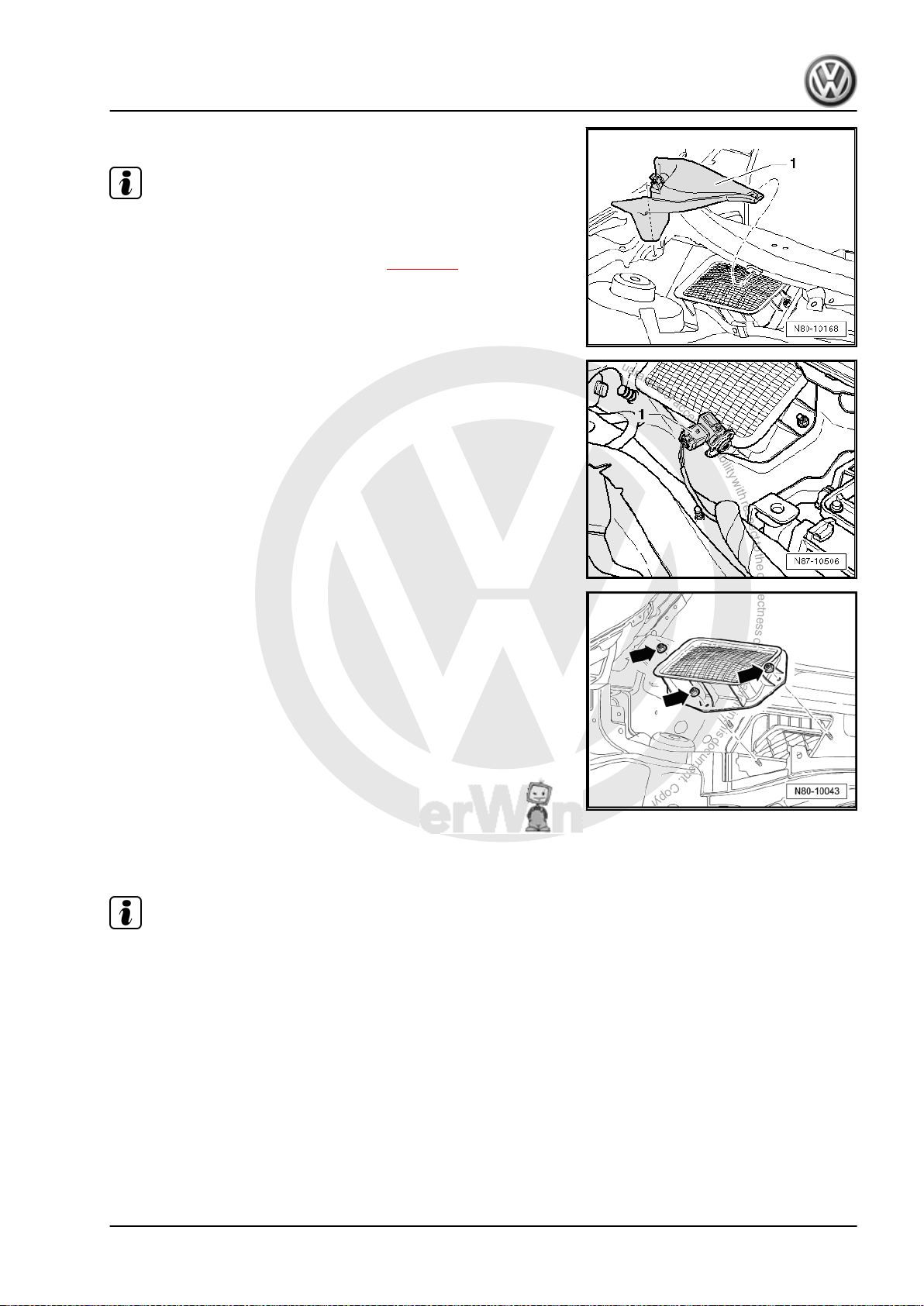
P
r
o
t
e
c
t
e
d
b
y
c
o
p
y
r
i
g
h
t
.
C
o
p
y
i
n
g
f
o
r
p
r
i
v
a
t
e
o
r
c
o
m
m
e
r
c
i
a
l
p
u
r
p
o
s
e
s
,
i
n
p
a
r
t
o
r
i
n
w
h
o
l
e
,
i
s
n
o
t
p
e
r
m
i
t
t
e
d
u
n
l
e
s
s
a
u
t
h
o
r
i
s
e
d
b
y
V
o
l
k
s
w
a
g
e
n
A
G
.
V
o
l
k
s
w
a
g
e
n
A
G
d
o
e
s
n
o
t
g
u
a
r
a
n
t
e
e
o
r
a
c
c
e
p
t
a
n
y
l
i
a
b
i
l
i
t
y
w
i
t
h
r
e
s
p
e
c
t
t
o
t
h
e
c
o
r
r
e
c
t
n
e
s
s
o
f
i
n
f
o
r
m
a
t
i
o
n
i
n
t
h
i
s
d
o
c
u
m
e
n
t
.
C
o
p
y
r
i
g
h
t
b
y
V
o
l
k
s
w
a
g
e
n
A
G
.
Heating, air conditioning - Edition 02.2008
– Remove cover -1- from plenum chamber.
Note
♦
On vehicles with Climatronic from week 45/2007, a retainer
with an air quality sensor -G238- is fitted on the air intake grille.
♦
Function of air quality sensor -G238- ⇒ page 56 .
– Release air quality sensor -G238- -1- and turn to right out of
retainer.
– Unscrew collar nuts -arrows- (2.5 ± 0.4 Nm) and remove air
intake grille upwards.
1.15.2 Installing
Install in reverse order.
Golf 2004 ➤
Note
Seal must seat properly on air intake screen.
Assembly sequence:
– Adjust air intake grille on metal collar.
– Hold air intake grille and first tighten lateral collar nuts
(2.5 ± 0.4 Nm), then tighten middle collar nut.
1.16 Removing and installing heater unit
Special tools and workshop equipment required
1. Repairing heater 19
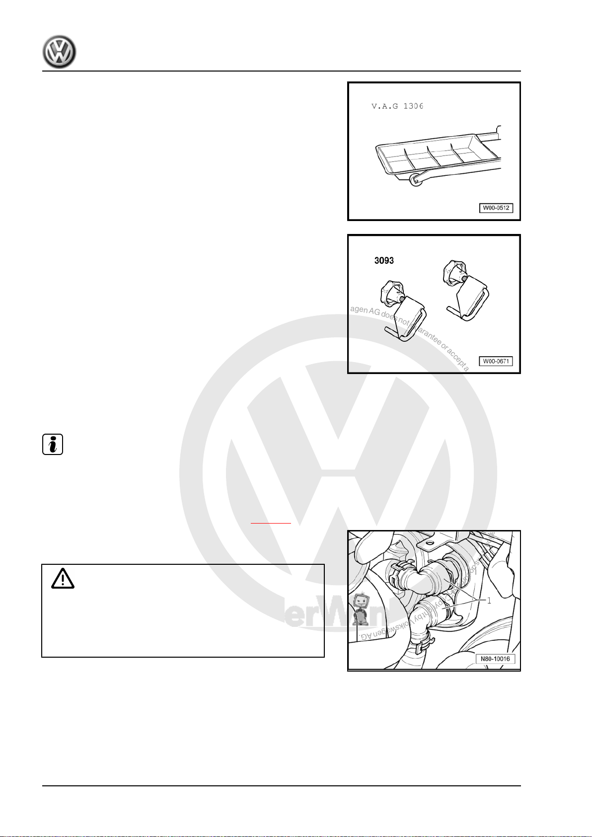
P
r
o
t
e
c
t
e
d
b
y
c
o
p
y
r
i
g
h
t
.
C
o
p
y
i
n
g
f
o
r
p
r
i
v
a
t
e
o
r
c
o
m
m
e
r
c
i
a
l
p
u
r
p
o
s
e
s
,
i
n
p
a
r
t
o
r
i
n
w
h
o
l
e
,
i
s
n
o
t
p
e
r
m
i
t
t
e
d
u
n
l
e
s
s
a
u
t
h
o
r
i
s
e
d
b
y
V
o
l
k
s
w
a
g
e
n
A
G
.
V
o
l
k
s
w
a
g
e
n
A
G
d
o
e
s
n
o
t
g
u
a
r
a
n
t
e
e
o
r
a
c
c
e
p
t
a
n
y
l
i
a
b
i
l
i
t
y
w
i
t
h
r
e
s
p
e
c
t
t
o
t
h
e
c
o
r
r
e
c
t
n
e
s
s
o
f
i
n
f
o
r
m
a
t
i
o
n
i
n
t
h
i
s
d
o
c
u
m
e
n
t
.
C
o
p
y
r
i
g
h
t
b
y
V
o
l
k
s
w
a
g
e
n
A
G
.
Golf 2004 ➤
Heating, air conditioning - Edition 02.2008
♦ Drip tray -V.A.G 1306-
♦ Hose clamps up to 40 mm Ø -VAS 3093-
♦ Compressed air gun, commercially available
1.16.1 Removing
Note
To improve access, depending on engine version, additional com‐
ponents must be removed e.g. engine cover ⇒ Rep. Gr. 10 .
– Remove dash panel ⇒ Rep. Gr. 70 .
– Remove right and left rear footwell air ducts ⇒ page 6 .
– Place drip tray -V.A.G 1306- beneath engine.
– Mark coolant hoses -1-
WARNING
Danger of scalding injuries.
When the engine is warm, the coolant temperature may be
above 100 °C. The cooling system is pressurised.
If necessary, release pressure before carrying out repairs.
20 Rep. Gr.80 - Heating
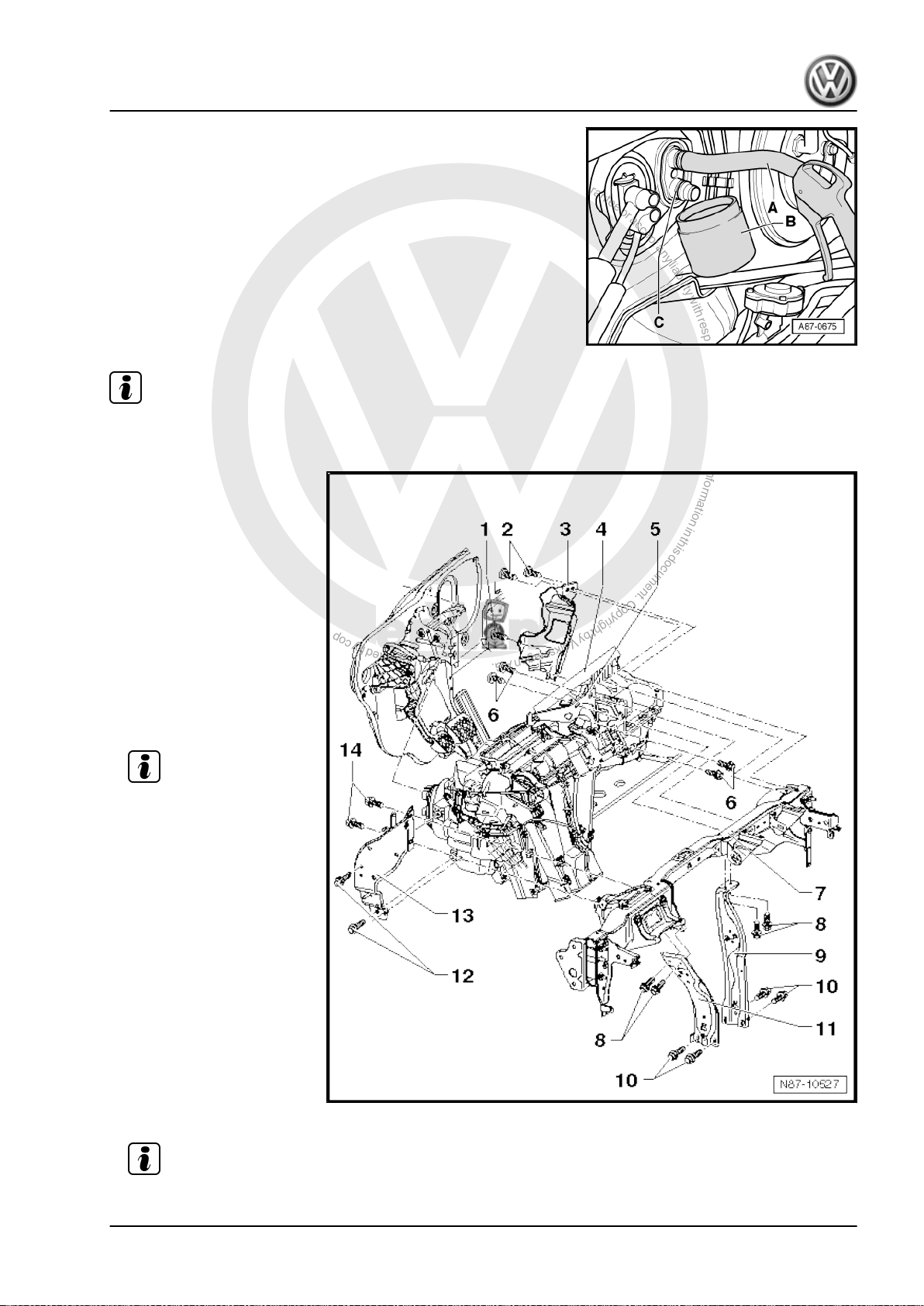
P
r
o
t
e
c
t
e
d
b
y
c
o
p
y
r
i
g
h
t
.
C
o
p
y
i
n
g
f
o
r
p
r
i
v
a
t
e
o
r
c
o
m
m
e
r
c
i
a
l
p
u
r
p
o
s
e
s
,
i
n
p
a
r
t
o
r
i
n
w
h
o
l
e
,
i
s
n
o
t
p
e
r
m
i
t
t
e
d
u
n
l
e
s
s
a
u
t
h
o
r
i
s
e
d
b
y
V
o
l
k
s
w
a
g
e
n
A
G
.
V
o
l
k
s
w
a
g
e
n
A
G
d
o
e
s
n
o
t
g
u
a
r
a
n
t
e
e
o
r
a
c
c
e
p
t
a
n
y
l
i
a
b
i
l
i
t
y
w
i
t
h
r
e
s
p
e
c
t
t
o
t
h
e
c
o
r
r
e
c
t
n
e
s
s
o
f
i
n
f
o
r
m
a
t
i
o
n
i
n
t
h
i
s
d
o
c
u
m
e
n
t
.
C
o
p
y
r
i
g
h
t
b
y
V
o
l
k
s
w
a
g
e
n
A
G
.
Heating, air conditioning - Edition 02.2008
– Clamp off coolant hoses -1- using hose clamps up to 40 mm Ø
-VAS 3093- and disconnect coolant hoses to heat exchanger.
– Push a piece of hose -A- onto upper connection of heat ex‐
changer.
– Hold a container -B- under lower connection -C-.
– Carefully blow remaining coolant out of heat exchanger using
a compressed air pistol at heat exchanger connection.
– Cover carpet in vehicle interior with waterproof foil and ab‐
sorbent paper.
Note
During removal, note lengths and locations of bolts for later installation.
1 - Bolt
❑ 4,5 ± 0.7 Nm
❑ Lower right on cable re‐
tainer to heater unit,
near bulkhead
2 - Bolts
❑ 4,5 ± 0.7 Nm
3 - Cable retainer
4 - Heater unit
Removing:
Golf 2004 ➤
– Separate connectors
from heater unit.
Note
– Remove both securing
nuts from convenience
system central control
unit -J393- and hang
central control unit to
side ⇒ Rep. Gr. 97 .
– Unscrew bolts -6- and
remove bracket -5-.
– Unscrew bolts -8- and
-10- and remove sup‐
ports -9- and -11-.
– Unscrew bolts -12- and
-14- and remove retain‐
er -13-.
– Remove bolts -2- and
-1- from cable retainer
-3-.
Note
– Remove heater unit.
1. Repairing heater 21
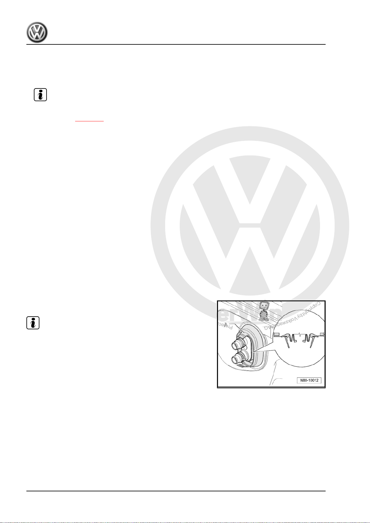
P
r
o
t
e
c
t
e
d
b
y
c
o
p
y
r
i
g
h
t
.
C
o
p
y
i
n
g
f
o
r
p
r
i
v
a
t
e
o
r
c
o
m
m
e
r
c
i
a
l
p
u
r
p
o
s
e
s
,
i
n
p
a
r
t
o
r
i
n
w
h
o
l
e
,
i
s
n
o
t
p
e
r
m
i
t
t
e
d
u
n
l
e
s
s
a
u
t
h
o
r
i
s
e
d
b
y
V
o
l
k
s
w
a
g
e
n
A
G
.
V
o
l
k
s
w
a
g
e
n
A
G
d
o
e
s
n
o
t
g
u
a
r
a
n
t
e
e
o
r
a
c
c
e
p
t
a
n
y
l
i
a
b
i
l
i
t
y
w
i
t
h
r
e
s
p
e
c
t
t
o
t
h
e
c
o
r
r
e
c
t
n
e
s
s
o
f
i
n
f
o
r
m
a
t
i
o
n
i
n
t
h
i
s
d
o
c
u
m
e
n
t
.
C
o
p
y
r
i
g
h
t
b
y
V
o
l
k
s
w
a
g
e
n
A
G
.
Golf 2004 ➤
Heating, air conditioning - Edition 02.2008
Installing:
Installation is carried out in the reverse order. When installing, note the following:
First tighten bolts -8- when installing supports -9- and -11-.
Note
– Have second mechanic guide both coolant pipes to heat exchanger through seal during installation of
heater unit ⇒ page 22 .
– Fill with coolant ⇒ Rep. Gr. 19 .
5 - Bracket
6 - Bolts
❑ 8 ± 1 Nm
7 - Mounting plate
8 - Bolts
❑ 9 ± 1.3 Nm
9 - Right support
10 - Bolts
❑ 20 ± 3 Nm
11 - Left support
12 - Bolts
❑ 9 ± 1.3 Nm
13 - Bracket
14 - Bolts
❑ 9 ± 1.3 Nm
Seal between heater unit and engine compartment
Note
Observe position of seal -A- during installation.
22 Rep. Gr.80 - Heating
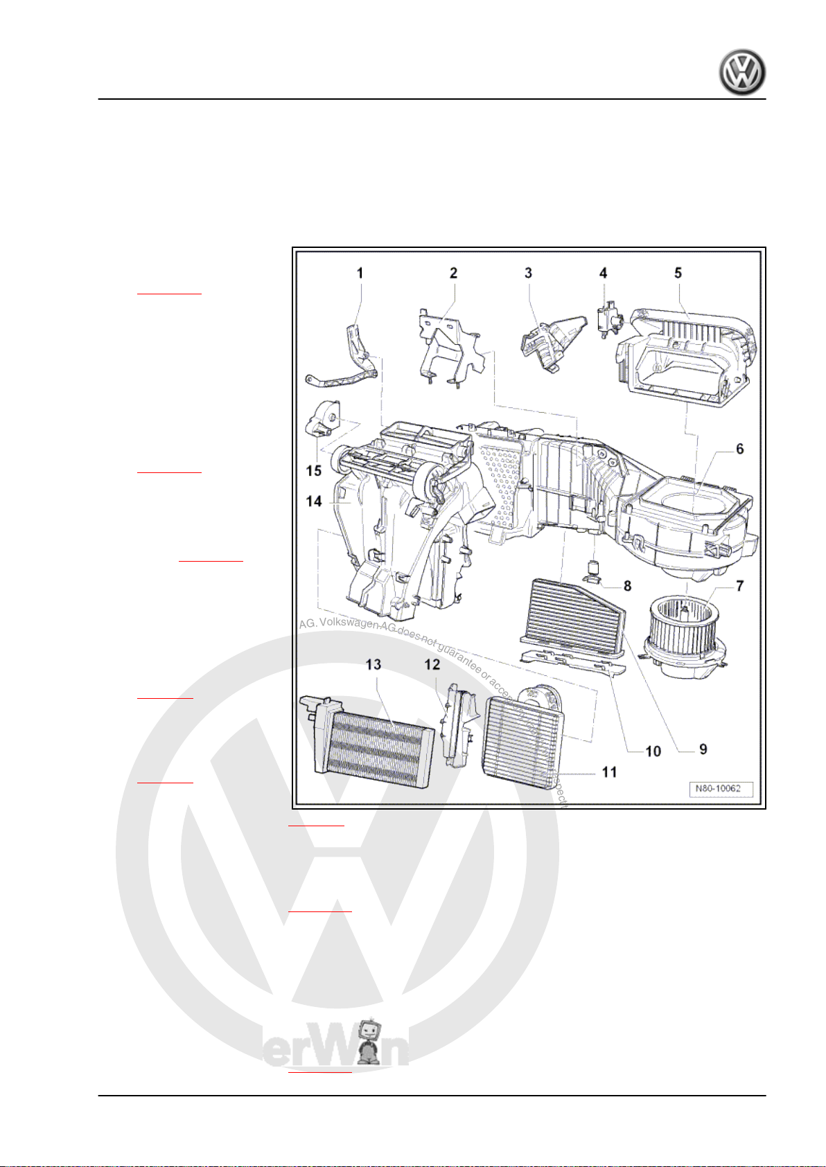
P
r
o
t
e
c
t
e
d
b
y
c
o
p
y
r
i
g
h
t
.
C
o
p
y
i
n
g
f
o
r
p
r
i
v
a
t
e
o
r
c
o
m
m
e
r
c
i
a
l
p
u
r
p
o
s
e
s
,
i
n
p
a
r
t
o
r
i
n
w
h
o
l
e
,
i
s
n
o
t
p
e
r
m
i
t
t
e
d
u
n
l
e
s
s
a
u
t
h
o
r
i
s
e
d
b
y
V
o
l
k
s
w
a
g
e
n
A
G
.
V
o
l
k
s
w
a
g
e
n
A
G
d
o
e
s
n
o
t
g
u
a
r
a
n
t
e
e
o
r
a
c
c
e
p
t
a
n
y
l
i
a
b
i
l
i
t
y
w
i
t
h
r
e
s
p
e
c
t
t
o
t
h
e
c
o
r
r
e
c
t
n
e
s
s
o
f
i
n
f
o
r
m
a
t
i
o
n
i
n
t
h
i
s
d
o
c
u
m
e
n
t
.
C
o
p
y
r
i
g
h
t
b
y
V
o
l
k
s
w
a
g
e
n
A
G
.
Golf 2004 ➤
Heating, air conditioning - Edition 02.2008
2 Dismantling and assembling heater
unit
2.1 Assembly overview – heater unit
1 - Temperature flap actuator
❑ Removing and installing
⇒ page 26
2 - Bracket
3 - Cover
4 - Fresh air and air recircula‐
tion flap control motor -V154-
❑ Checking: vehicle diag‐
nosis, testing and infor‐
mation system -VAS
5051- (or later model)
❑ Removing and installing
⇒ page 11
❑ Renewing: initiate basic
settings using vehicle
diagnosis, testing and
information system VAS 5051- or successor
model ⇒ page 42
5 - Air intake housing
❑ With air recirculation
flap
6 - Heater unit
7 - Fresh air blower -V2-
❑ Removing and installing
⇒ page 3
8 - Fresh air blower series re‐
sistor with overheating fuse N24-
9 - Dust and pollen filter
10 - Cover
11 - Heat exchanger
12 - Heat exchanger trim
13 - Auxiliary air heater element -Z35-
Vehicles up to 1K-7P015628 and 1K-7B084800
❑ Removing and installing
⇒ page 3
❑ Removing and installing ⇒ page 4
❑ For dust and pollen filter.
❑ Removing and installing ⇒ page 12
❑ With auxiliary air heater control unit -J604- .
❑ Checking: with vehicle diagnostic, testing and information system -VAS 5051- (or later model), under
Heating, ventilation, air conditioning; Systems capable of self-diagnosis; Auxiliary heating; Electrical
components.
❑ Removing and installing ⇒ page 15
2. Dismantling and assembling heater unit 23

P
r
o
t
e
c
t
e
d
b
y
c
o
p
y
r
i
g
h
t
.
C
o
p
y
i
n
g
f
o
r
p
r
i
v
a
t
e
o
r
c
o
m
m
e
r
c
i
a
l
p
u
r
p
o
s
e
s
,
i
n
p
a
r
t
o
r
i
n
w
h
o
l
e
,
i
s
n
o
t
p
e
r
m
i
t
t
e
d
u
n
l
e
s
s
a
u
t
h
o
r
i
s
e
d
b
y
V
o
l
k
s
w
a
g
e
n
A
G
.
V
o
l
k
s
w
a
g
e
n
A
G
d
o
e
s
n
o
t
g
u
a
r
a
n
t
e
e
o
r
a
c
c
e
p
t
a
n
y
l
i
a
b
i
l
i
t
y
w
i
t
h
r
e
s
p
e
c
t
t
o
t
h
e
c
o
r
r
e
c
t
n
e
s
s
o
f
i
n
f
o
r
m
a
t
i
o
n
i
n
t
h
i
s
d
o
c
u
m
e
n
t
.
C
o
p
y
r
i
g
h
t
b
y
V
o
l
k
s
w
a
g
e
n
A
G
.
Golf 2004 ➤
Heating, air conditioning - Edition 02.2008
Vehicles from 1K-7P015629 and 1K-7B084801
❑ A three-level auxiliary air heater element -Z35- is fitted here; it is controlled by the respective engine
control unit via relays.
❑ Installed only in vehicles with diesel engines without supplementary heater.
❑ Removing and installing ⇒ page 16
14 - Air distribution housing
15 - Air distribution flap actuator
❑ Removing and installing ⇒ page 26
2.2 Removing and installing air distribution housing
2.2.1 Removing
– Remove heater unit ⇒ page 19 .
– Separate all available connectors from air distribution housing.
24 Rep. Gr.80 - Heating
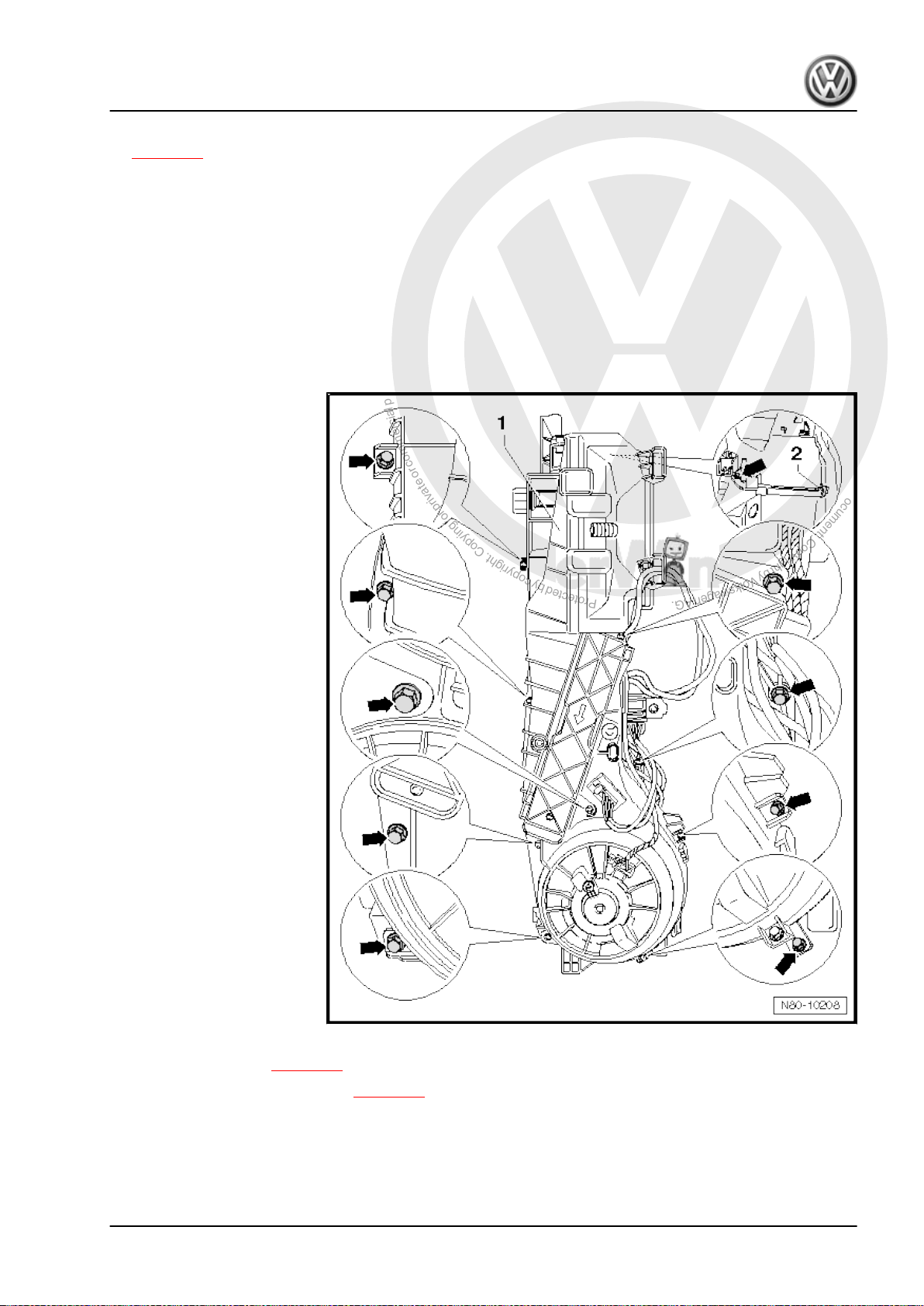
P
r
o
t
e
c
t
e
d
b
y
c
o
p
y
r
i
g
h
t
.
C
o
p
y
i
n
g
f
o
r
p
r
i
v
a
t
e
o
r
c
o
m
m
e
r
c
i
a
l
p
u
r
p
o
s
e
s
,
i
n
p
a
r
t
o
r
i
n
w
h
o
l
e
,
i
s
n
o
t
p
e
r
m
i
t
t
e
d
u
n
l
e
s
s
a
u
t
h
o
r
i
s
e
d
b
y
V
o
l
k
s
w
a
g
e
n
A
G
.
V
o
l
k
s
w
a
g
e
n
A
G
d
o
e
s
n
o
t
g
u
a
r
a
n
t
e
e
o
r
a
c
c
e
p
t
a
n
y
l
i
a
b
i
l
i
t
y
w
i
t
h
r
e
s
p
e
c
t
t
o
t
h
e
c
o
r
r
e
c
t
n
e
s
s
o
f
i
n
f
o
r
m
a
t
i
o
n
i
n
t
h
i
s
d
o
c
u
m
e
n
t
.
C
o
p
y
r
i
g
h
t
b
y
V
o
l
k
s
w
a
g
e
n
A
G
.
– Remove heat exchanger together with coolant pipes
⇒ page 12 .
– Remove bolts -arrows- (1.4 Nm).
– Remove air distribution housing -1- from heater unit -2-.
2.2.2 Installing
Install in reverse order.
2.3 Dismantling and assembling heater unit
2.3.1 Dismantling
Heating, air conditioning - Edition 02.2008
Golf 2004 ➤
– Remove heater unit ⇒ page 19 .
– Remove air distribution housing ⇒ page 24 .
– Remove clip -2- and bolts -arrows- from heater unit.
– Unfold heater unit.
2.3.2 Assembling
Assemble in reverse order.
2. Dismantling and assembling heater unit 25
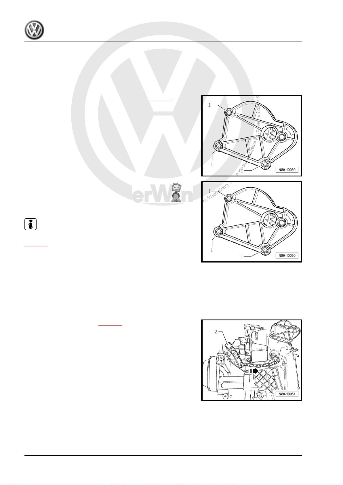
P
r
o
t
e
c
t
e
d
b
y
c
o
p
y
r
i
g
h
t
.
C
o
p
y
i
n
g
f
o
r
p
r
i
v
a
t
e
o
r
c
o
m
m
e
r
c
i
a
l
p
u
r
p
o
s
e
s
,
i
n
p
a
r
t
o
r
i
n
w
h
o
l
e
,
i
s
n
o
t
p
e
r
m
i
t
t
e
d
u
n
l
e
s
s
a
u
t
h
o
r
i
s
e
d
b
y
V
o
l
k
s
w
a
g
e
n
A
G
.
V
o
l
k
s
w
a
g
e
n
A
G
d
o
e
s
n
o
t
g
u
a
r
a
n
t
e
e
o
r
a
c
c
e
p
t
a
n
y
l
i
a
b
i
l
i
t
y
w
i
t
h
r
e
s
p
e
c
t
t
o
t
h
e
c
o
r
r
e
c
t
n
e
s
s
o
f
i
n
f
o
r
m
a
t
i
o
n
i
n
t
h
i
s
d
o
c
u
m
e
n
t
.
C
o
p
y
r
i
g
h
t
b
y
V
o
l
k
s
w
a
g
e
n
A
G
.
Golf 2004 ➤
Heating, air conditioning - Edition 02.2008
2.4 Removing and installing air distribution flap actuator
2.4.1 Removing
– Remove dash panel ⇒ Rep. Gr. 70 .
– Unclip flexible shaft from adapter for controls ⇒ page 9 .
– Remove bolts -1- and remove air distribution flap actuator.
2.4.2 Installing
– Arrows on gears must align.
– Position air distribution flap actuator and tighten bolts -1-.
Note
After installation, check operation of air distribution flap
⇒ page 9 .
2.5 Removing and installing temperature flap actuator
2.5.1 Removing
– Remove driver side footwell trim ⇒ Rep. Gr. 68 .
– Remove left footwell vent ⇒ page 7 .
– Unclip cable on temperature flap actuator -2-.
– Release catch -1- and press temperature flap actuator in
-direction of arrow- to stop.
– Pull off temperature flap actuator.
2.5.2 Installing
Install in reverse order.
26 Rep. Gr.80 - Heating
 Loading...