


Volkswagen 1.4 16v Polo 2003 Owner's Manual
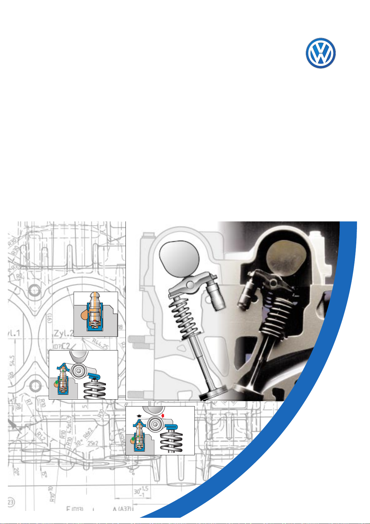
The 1.4-ltr. 16V 55kW Engine
with roller-type cam follower
Design and Function
S
196
.
o
N
E
M
M
A
R
G
O
R
P
Y
D
U
T
S
-
F
L
E

Whether it’s a matter of better fuel economy, higher engine output or lower exhaust emissions - the
demands on engines are constantly increasing.
This presents our engineers with new tasks, with the result that the Volkswagen engine range is constantly
growing.
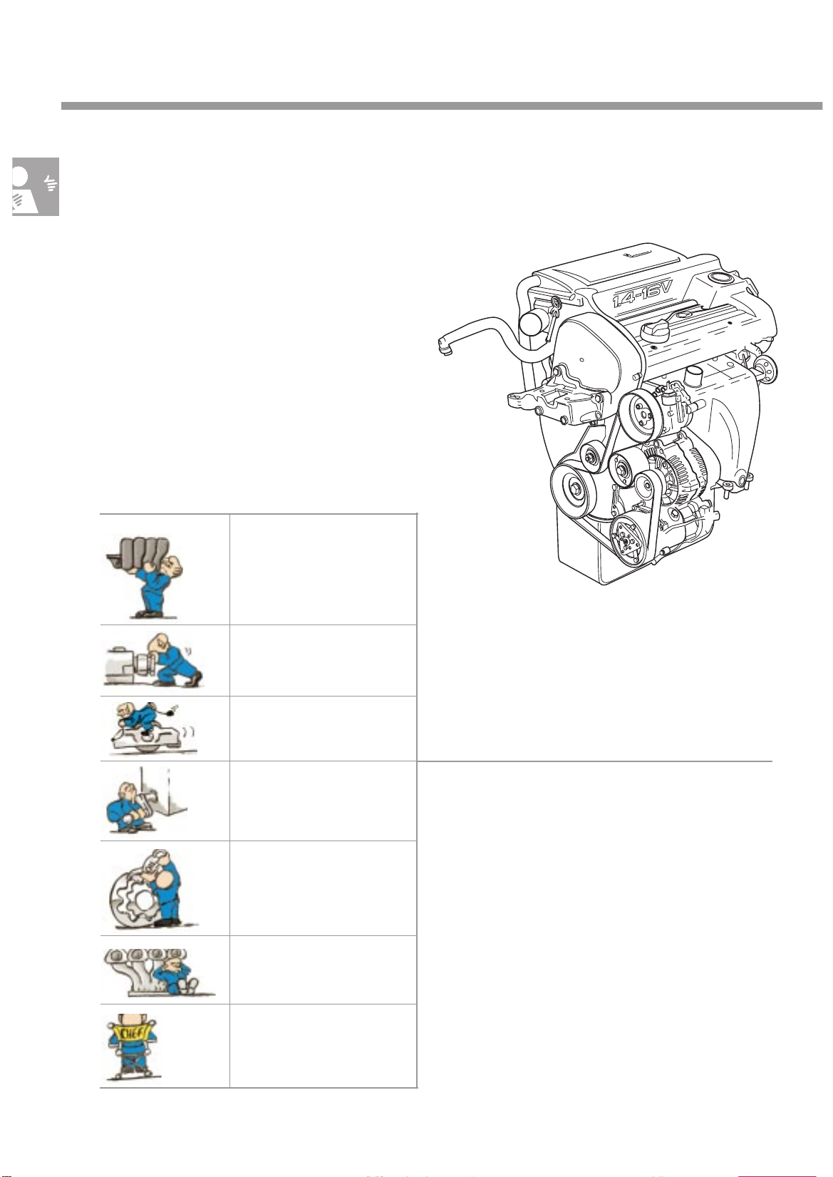
Example: weight saving
During development, the weight of the new 1.4-ltr. 16V 55kW engine was reduced by about 10 kg by
modifying its design.
This self-study programme explains the technical
innovations in our engine range using the 1.4-ltr.
16V 55kW engine as an example.
Apart from minor differences in the engine
mechanics, the 1.6-lr. 16V 88 kW engine for the
Polo GTI will have these new features, too.
The Self-Study Programme
is not a Workshop Manual.
2
196_168
These differences arise out of the various technical demands on the engines and are described
in this Self-Study Programme.
New Importan
t
Precise instructions for testing, adjustment and
repair can be found in the appropriate Workshop
Manual.

At a glance
Introduction . . . . . . . . . . . . . . . . . . . . . . . . . . . . . . . . . 4
Specifications . . . . . . . . . . . . . . . . . . . . . . . . . . . . . . . . . . . . . . . . . . 5
Engine mechanics . . . . . . . . . . . . . . . . . . . . . . . . . . . . . 6
Intake manifold . . . . . . . . . . . . . . . . . . . . . . . . . . . . . . . . . . . . . . . . 6
Valve gear . . . . . . . . . . . . . . . . . . . . . . . . . . . . . . . . . . . . . . . . . . . . 7
Valve actuation . . . . . . . . . . . . . . . . . . . . . . . . . . . . . . . . . . . . . . . . 8
toothed belt drive . . . . . . . . . . . . . . . . . . . . . . . . . . . . . . . . . . . . . . 11
Crankcase . . . . . . . . . . . . . . . . . . . . . . . . . . . . . . . . . . . . . . . . . . . 12
Crankshaft . . . . . . . . . . . . . . . . . . . . . . . . . . . . . . . . . . . . . . . . . . . 13
Sealing flange . . . . . . . . . . . . . . . . . . . . . . . . . . . . . . . . . . . . . . . . 14
Oil pump . . . . . . . . . . . . . . . . . . . . . . . . . . . . . . . . . . . . . . . . . . . . 16
Con rod . . . . . . . . . . . . . . . . . . . . . . . . . . . . . . . . . . . . . . . . . . . . . 18
Exhaust system . . . . . . . . . . . . . . . . . . . . . . . . . . . . . . . . . . . . . . . . 19
Engine management . . . . . . . . . . . . . . . . . . . . . . . . . . 21
Engine control unit . . . . . . . . . . . . . . . . . . . . . . . . . . . . . . . . . . . . .21
System overview . . . . . . . . . . . . . . . . . . . . . . . . . . . . . . . . . . . . . . 22
Static high-voltage distribution . . . . . . . . . . . . . . . . . . . . . . . . . . 24
Engine speed sender G28 . . . . . . . . . . . . . . . . . . . . . . . . . . . . . . 25
Hall sender G40 . . . . . . . . . . . . . . . . . . . . . . . . . . . . . . . . . . . . . . 26
Functional diagram . . . . . . . . . . . . . . . . . . . . . . . . . . . . . . . . . . . 28
Self-diagnosis. . . . . . . . . . . . . . . . . . . . . . . . . . . . . . . . . . . . . . . . . 30
Service . . . . . . . . . . . . . . . . . . . . . . . . . . . . . . . . . . . . .32
Special-purpose tools . . . . . . . . . . . . . . . . . . . . . . . . . . . . . . . . . . 32
3
Introduction
One of a “new generation”
The 1.4-ltr. 16V 55kW engine is the first of a new
generation of engines featuring roller-type cam
followers.
It is fundamentally different from
the 1.4-ltr. 16V 74kW engine with bucket tappets.
The main differences are:
- the die cast aluminium crankcase
- the cylinder head, where only the existing
valve clearance and angle have been
adopted.
New and advanced developments include:
the plastic intake manifold
the cylinder head and
camshaft housing
valves are activated by
roller-type cam followers
the crankcase is made of
die cast aluminium
the duocentric oil pump
196_068
The overall effects of these design modifications are:
- significant reduction in fuel consumption,
- performance on a par with
predecessor models,
- weight savings and
- compliance with the more stringent
exhaust gas
limit values now in effect in Germany.
the exhaust manifold
the Magneti Marelli 4AV
engine management
system
4
Specifications
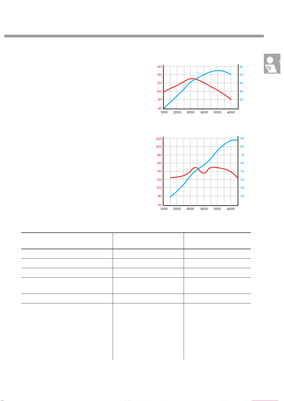
1.4-ltr. 16V 55kW engine
The 1.4-ltr. engine develops 128Nm of torque at
3200rpm. Maximum output is 55kW at
5000rpm.
1.6-ltr. 16V 88kW engine
By comparison, the 1.6-ltr. engine develops
148Nm of torque at 3400rpm and a maximum
output of 88kW at 6200rpm.
Torque
[Nm]
Torque
[Nm]
Output
[kW]
196_070
Engine speed [rpm]
Output
[kW]
1.6-ltr. engine1.4-ltr. engine
Engine code AHW
AKQ exhaust emission level D3
Displacement [cm
3
] 1390 1598
Bore/stroke [mm] 76.5 / 75.6 76.5 / 86.9
Compression ratio 10.5:1 10.6:1
Mixture preparation
Magneti Marelli 4AV Magneti Marelli 4AV
Engine management system
Fuel [RON] 95 / 91 98 / 95
Exhaust gas post-treatment Lambda control,
main catalytic converter for
MVEG-A II for the AHW engine
additional micro catalytic converter for exhaust emission level
D3 for the AKQ engine
AJV exhasut emission level D3
Lambda control,
primary and
main catalytic converters
for exhaust emission level D3
196_088
Engine speed [rpm]
The knock control lets you run the 1.4- ltr. and 1.6-ltr. engines on RON 91 and RON 95 fuel respectively. This may result in a slight loss of power and torque.
5
Engine Mechanics
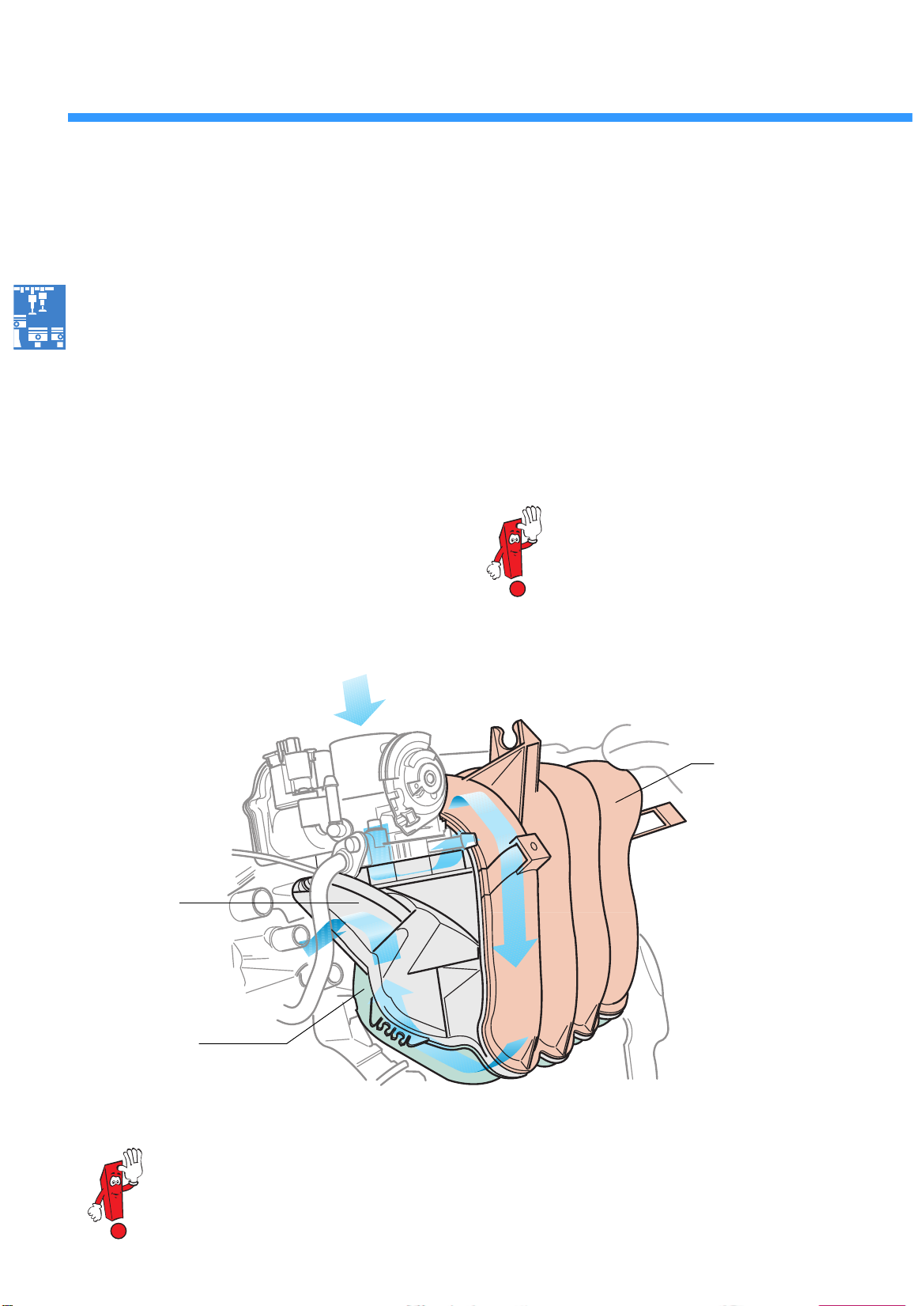
The plastic intake manifold
consists of three component parts which are welded together. The material is made of highgrade polyamide which is resistant to temperatures of up to 140°C for short periods of time.
The use of plastics has made it possible to keep
the weight of the intake manifold down to three
kilograms. As a result, the intake manifold is roughly 36% lighter than a comparable intake manifold made of aluminium.
The plastic intake manifold also has a very
smooth surface, and this improves the induced
air flow.
induced air
The following components are mounted in the
plastic intake manifold:
- the injectors,
- the fuel distributor,
- the throttle valve control unit and
- the intake manifold pressure sender and the
intake air temperature sender.
The air filter housing is secured to the plastic intake manifold by two screws.
The max. permissible tightening torque is
3.5Nm.
Middle section
Upper/lower parts of
intake manifold
An aluminium intake manifold is used for the 1.6-ltr. 16V 88kW engine.
It has been adapted to the engine’s requirements.
Upper shell
The plastic intake manifold
of the 1.4-ltr. engine
196_071
6
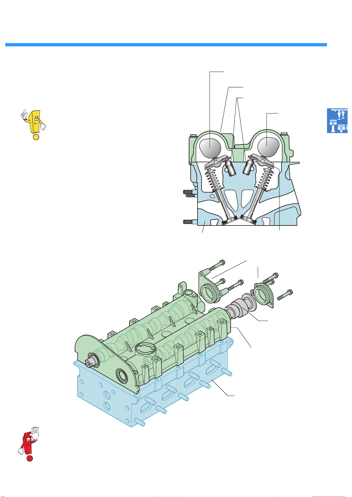
Valve gear
is accommodated in the cylinder head and
camshaft housing.
The camshaft housing is by and large
identical to the cylinder head cover
which was previously used as standard.
What’s new is that the camshafts are
now inserted into the housing. The bearing
covers and camshaft housing limit the axial clearance of the camshafts.
The camshafts run in three bearings.
The valve assembly comprising valves, rollertype cam followers and hydraulic support elements
is located in the cylinder head.
Exhaust
camshaft
Camshaft housing
Hydraulic support element
Intake
camshaft
196_018
Roller-type cam followerCylinder head
Bearing cover
Camshaft housing
196_075
Cylinder head
Inserted camshaft
The gasket between the camshaft housing and the cylinder head is in the form of a fluid seal.
Do not apply the sealant too thickly, since this may cause excess sealant to enter the oil drillings
and damage the engine.
7
Engine Mechanics
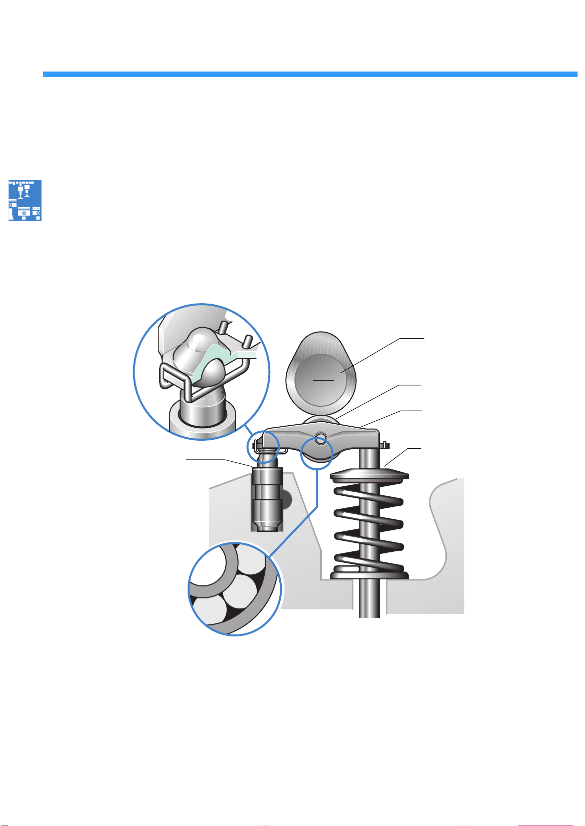
Valve activation
With this engine generation, the valves are activated via a roller-type cam follower with a
hydraulic
support element.
Advantages:
- less friction
- fewer moving masses.
Conclusion:
Less engine power is required to drive the camshafts.
support element
Low-friction
roller bearing
Camshaft
Cam roll
Roller-type
cam follower
ValveHydraulic
196_010
Design
The roller-type cam follower comprises a sheetmetal moulding acting as a lever and a cam roll
with a roller bearing.
The cam follower is clipped onto the support element and seated on the valve.
8
The hydraulic support element has the same
function as the hydraulic bucket tappet. It serves
as a hydraulic valve lifter and support for the
roller-type cam follower.
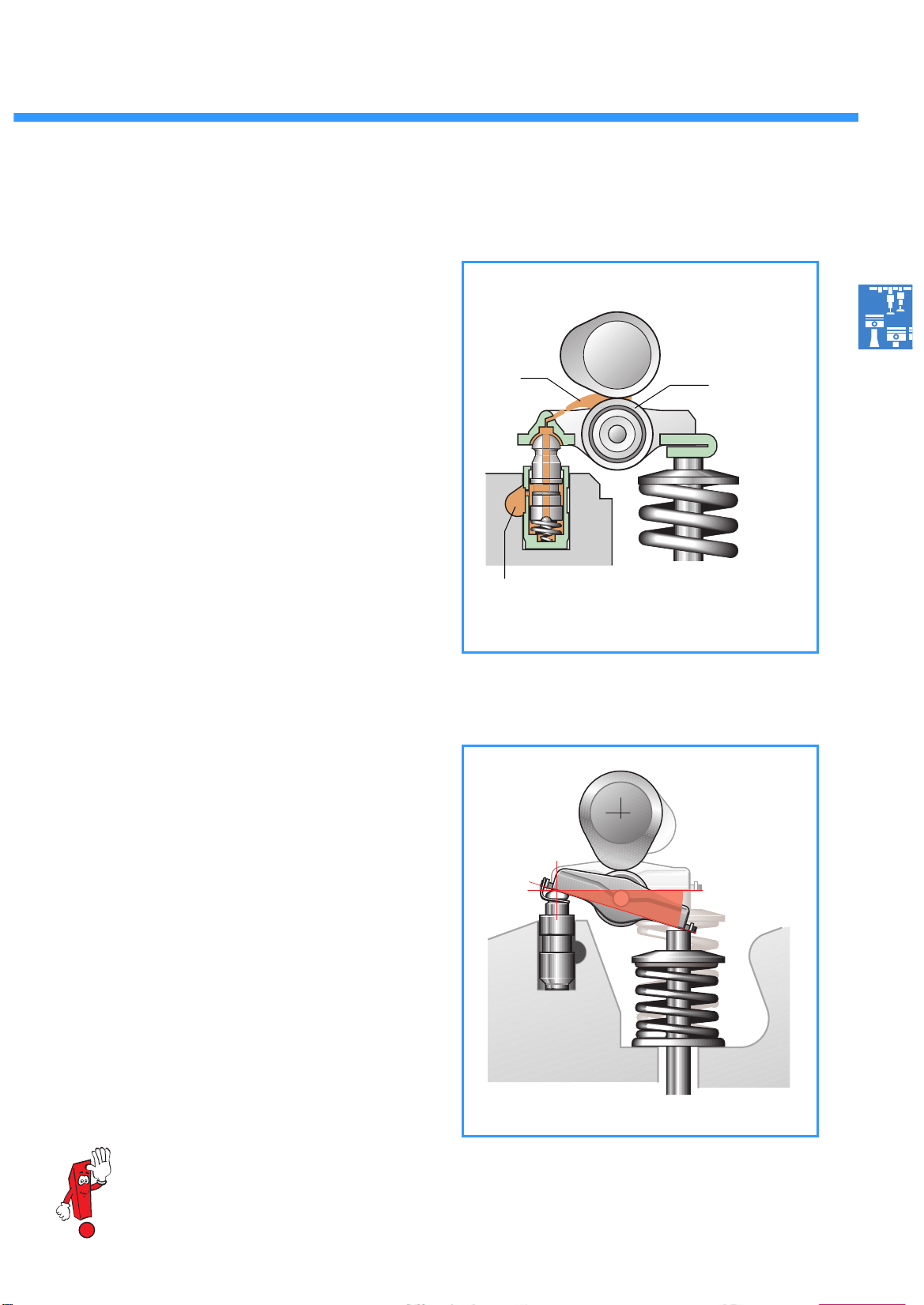
The lubrication system
Lubricant flows between the hydraulic support
element and the roller-type cam follower as well
as between the cams and the cam roll along an
oil duct integrated in the support element.
Oil is injected into the cam roll through a drilling
in the roller-type cam follower.
Oil
Cam roll
Function
The support element serves as a pivot for the roller-type cam follower. The cam contacts the cam
roll and presses the lever down. The lever in turn
activates the valve.
A high valve lift is achieved with a relatively
small cam due to the fact that the leverage between the cam roll and support element is smaller
than between the valve and support element.
Lubricant duct
196_009
It is not possible to inspect the hydraulic support elements.
196_011
9
Engine Mechanics
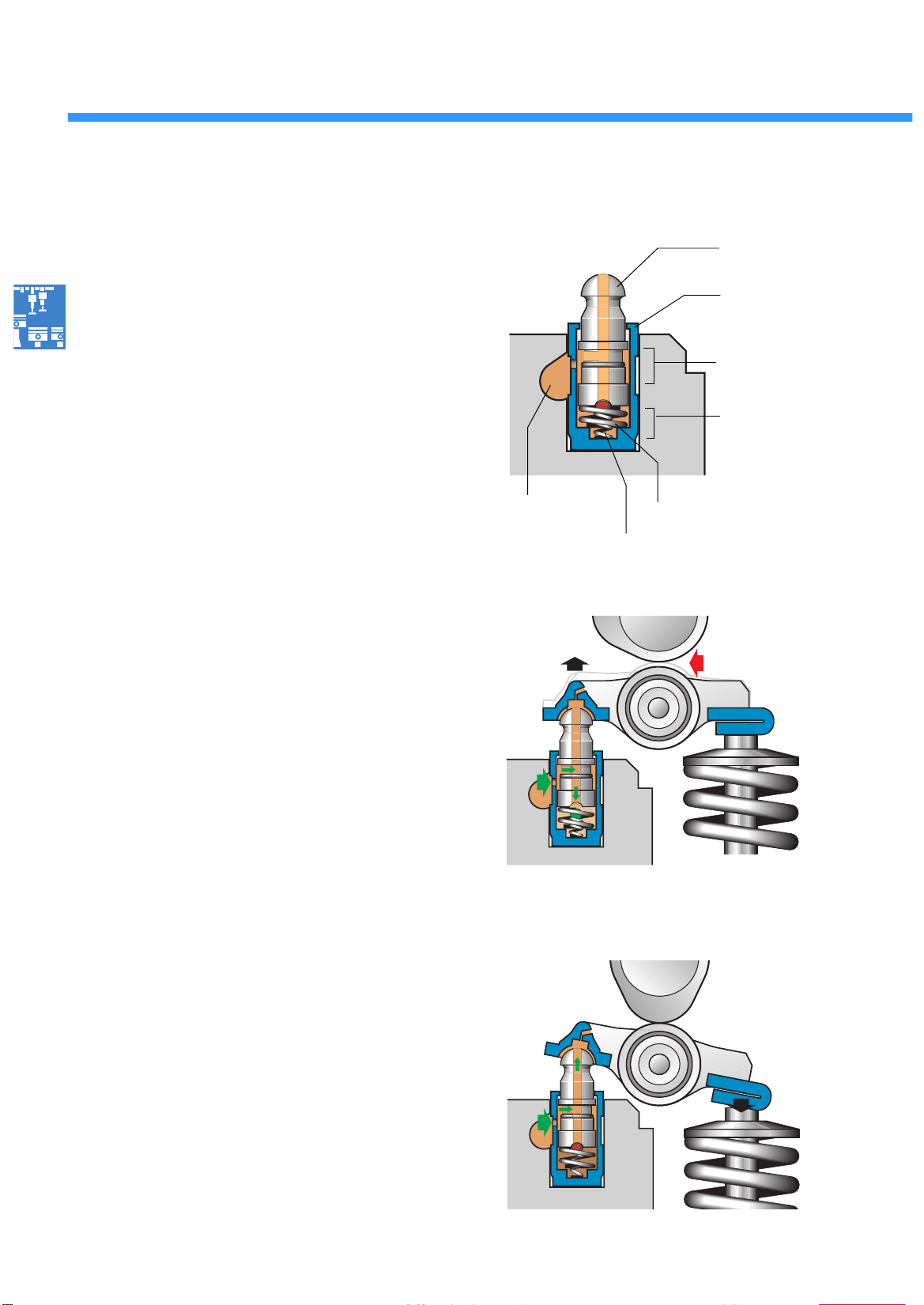
The hydraulic support element
serves as a support for the roller-type cam
follower and hydraulic valve lifter.
Design
The support element is connected to the oil
circuit. It comprises the following elements:
- a piston,
- a cylinder and
- a piston spring.
A small ball, in combination with a pressure
spring integrated in the lower oil chamber,
makes up the one-way valve.
Hydraulic valve lifter
If valve backlash occurs, the piston spring forces
the piston out of the cylinder until the cam roll
makes contact with the cam. When the piston is
pressed out of the cylinder, the oil pressure in the
lower oil chamber drops.
The one-way-valve opens and surplus oil flows
into the oil chamber.
The one-way-valve closes when the pressure
between the lower and upper oil chambers has
been equalised.
Oil inlet
Piston with
drilling
Cylinder
Upper
oil chamber
Lower
oil chamber
196_014
Piston spring
One-way valve
Valve clearance
196_016
10
Valve lift
When the cam contacts the cam roll, the pressure inside the lower oil chamber rises because
the oil here cannot be compressed. The piston
cannot be forced any further into the cylinder.
Thus, the support element acts as a rigid support
for the roller-type cam follower.
The inlet or exhaust valve opens.
196_017
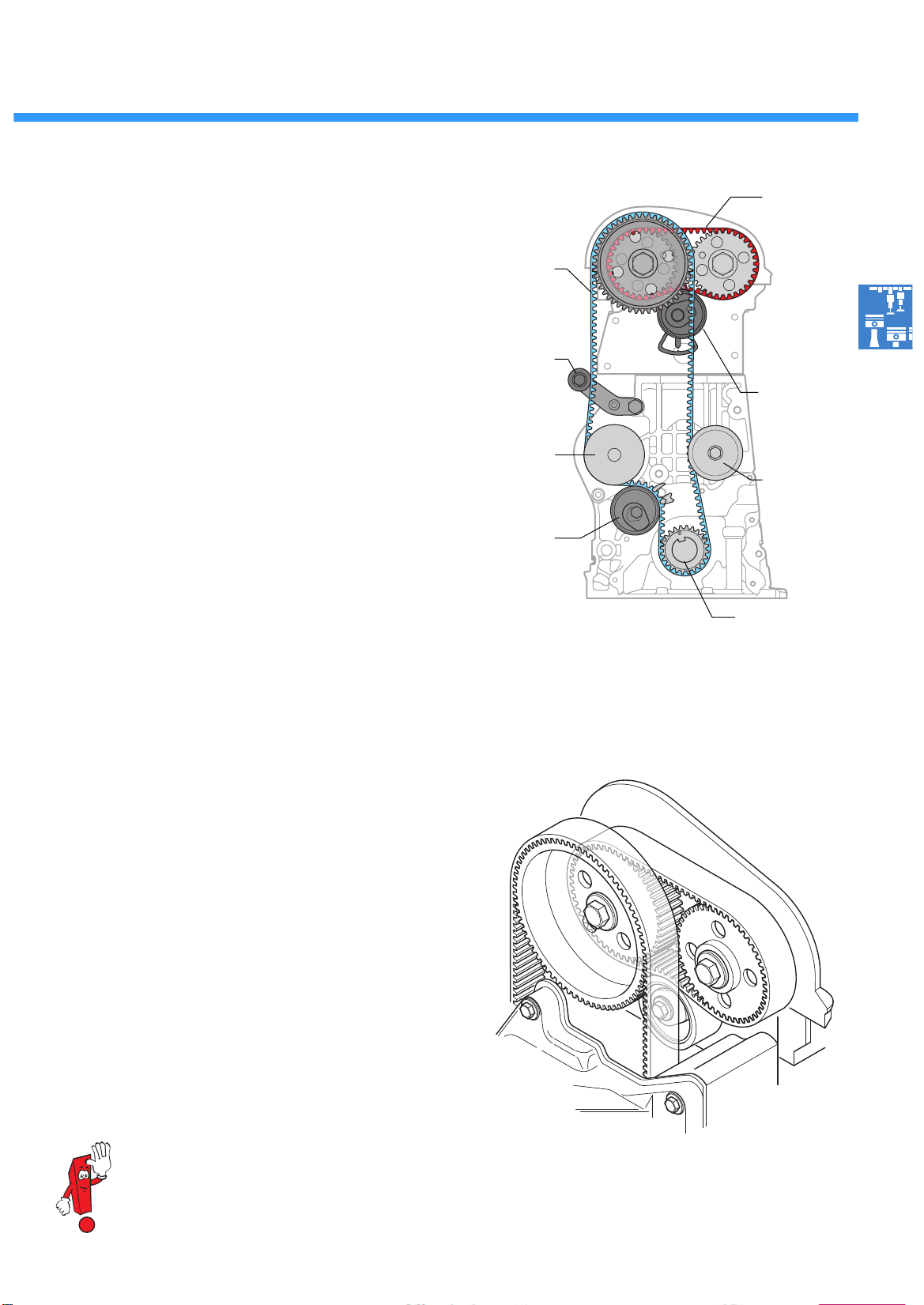
The toothed belt drive
The toothed belt drive is divided into a main
drive and a connecting drive on account of the
small overall width of the of the cylinder head.
Main drive
The coolant pump and the intake camshaft are
driven by the crankshaft by means of a toothed
belt integrated in the main drive. An automatic
tension pulley and two deflection pulleys reduce
toothed belt fluctuation.
Main drive
Deflection
pulley
Belt pulley
Coolant pump
Tension pulley
Main drive
Connecting drive
Tension pulley
Connecting drive
Deflection
pulley
196_021
Belt-driven
crankshaft gear
The connecting drive
is located outside the cylinder head.
The exhaust camshaft is driven by the
intake camshaft by means of a second toothed
belt integrated in the connecting drive.
Again, an automatic tension pulley reduces toothed belt fluctuation.
You can find exact instructions for adjustment the camshaft timing in the Workshop Manual.
196_024
11
 Loading...