


Volkswagen Crafter User Manual
Service Training
Self-study Programme 370
The Crafter
Electrical system
Design and function
Commercial
Vehicles

Innovations in automotive engineering are also taking
place in the commercial vehicle segment.
The Volkswagen Crafter is therefore fitted with
extensive electrical equipment and with electrical and
optical data bus systems.
In comparison with the predecessor model,
these systems enable familiar electrical
functions to be actuated in different ways and
new functions to be implemented.
This self-study programme is intended to explain
these functions and help you to understand
their interconnections better.
The self-study programme shows the design and
function of new developments.
The contents will not be updated.
2
S370_087
NEW Important
Note
For current testing, adjustment and repair
instructions, refer to the relevant
service literature.
Contents
Introduction . . . . . . . . . . . . . . . . . . . . . . . . . . . . . . . . . . . . . . . . . . . . . . . . . . . 4
Vehicle electrical system. . . . . . . . . . . . . . . . . . . . . . . . . . . . . . . . . . . . . . . . 14
Ignition lock . . . . . . . . . . . . . . . . . . . . . . . . . . . . . . . . . . . . . . . . . . . . . . . . . 46
Anti-theft system . . . . . . . . . . . . . . . . . . . . . . . . . . . . . . . . . . . . . . . . . . . . . .50
Dash panel . . . . . . . . . . . . . . . . . . . . . . . . . . . . . . . . . . . . . . . . . . . . . . . . . . .56
Convenience systems . . . . . . . . . . . . . . . . . . . . . . . . . . . . . . . . . . . . . . . . . . 60
Tachograph . . . . . . . . . . . . . . . . . . . . . . . . . . . . . . . . . . . . . . . . . . . . . . . . . . .76
Special control units . . . . . . . . . . . . . . . . . . . . . . . . . . . . . . . . . . . . . . . . . . . .78
Service . . . . . . . . . . . . . . . . . . . . . . . . . . . . . . . . . . . . . . . . . . . . . . . . . . . . . 80
Glossary. . . . . . . . . . . . . . . . . . . . . . . . . . . . . . . . . . . . . . . . . . . . . . . . . . . . . 82
Test yourself . . . . . . . . . . . . . . . . . . . . . . . . . . . . . . . . . . . . . . . . . . . . . . . . . 83
3
Introduction
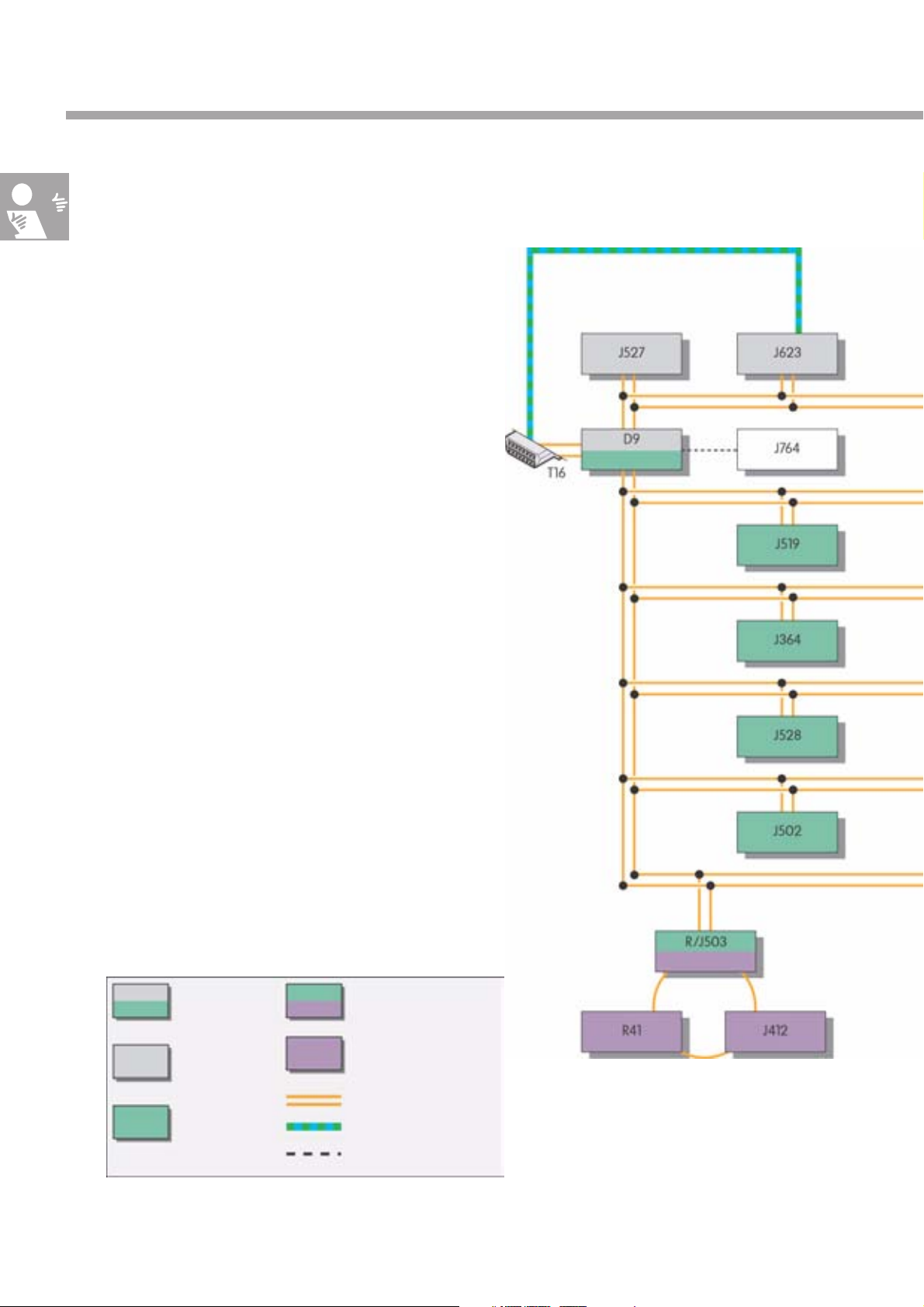
Data bus systems
Data bus networking
The Volkswagen Crafter's control units are networked
via the CAN data bus and the MOST data bus.
Networking enables data to be exchanged between
the individual control units.
Instead of using conventional (discrete) cable
connections, the data are transmitted via the data
buses in digital form as an electrical signal or
as a light signal. This makes it possible to make data
available to several control units.
The CAN data bus is sub-divided into three individual
systems, the CAN drive data bus, the CAN
convenience data bus and the CAN diagnostic data
bus.
All three bus systems are connected to each other via
the electronic ignition lock D9, and are therefore able
to exchange information.
Diagnostic
interface
CAN drive
data bus
CAN
convenience
data bus
MOST data bus
interface
MOST data bus
Data bus
K-wire
Serial data cable
S370_080
4
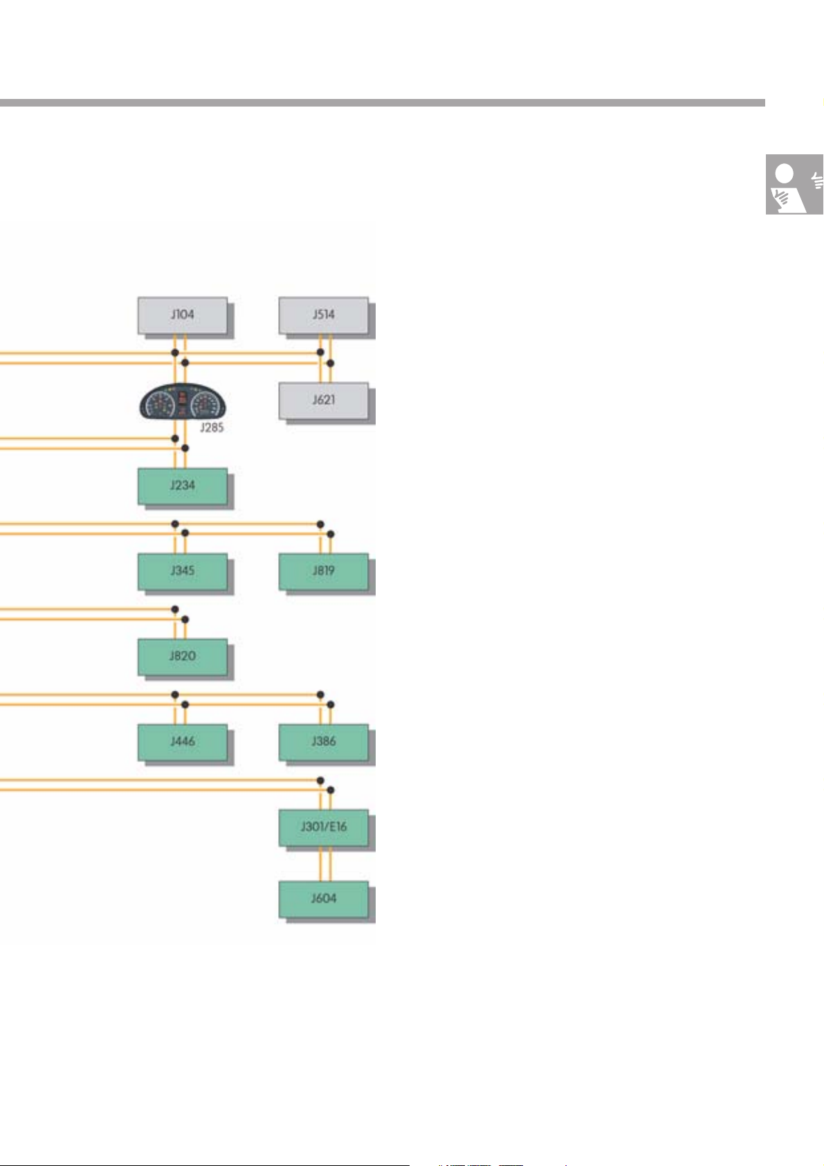
Legend
D9 Electronic ignition lock
E16 Heater/heat output switch
J104 ABS control unit
J234 Airbag control unit
J285 Control unit in dash panel insert
J301 Air conditioning system control unit
J345 Trailer detector control unit
J364 Auxiliary heater control unit
J386 Driver door control unit
J412 Mobile telephone operating electronics control unit
J446 Parking aid control unit
J502 Tyre pressure monitor control unit
J503 Control unit with display for radio and navigation
J514 Electronic manual gearbox control unit
J519 Onboard supply control unit
J527 Steering column electronics control unit
J528 Roof electronics control unit
J604 Auxiliary air heater control unit
J621 Tachograph control unit
J623 Engine control unit
J764 Electronic steering column lock control unit
J819 Control unit for middle of dash panel
J820 Control unit for programmable special functions
S370_001
R Radio
R41 CD changer
T16 16-pin connector (diagnostic connection)
5
Introduction
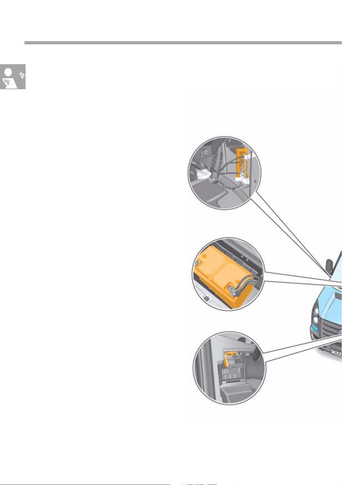
Installation locations of the electrical components
Overview of installation locations
The vehicle electrical system has a decentralised
structure; the fuse and relay installation locations are
therefore in different locations throughout the vehicle.
Junction boxes 2 and 3 for
bus systems,
on the right A pillar
Fuse holder (SA),
on right-hand side of battery, visible only following
removal
Connector (T16, diagnostic connection),
on the left A pillar
6
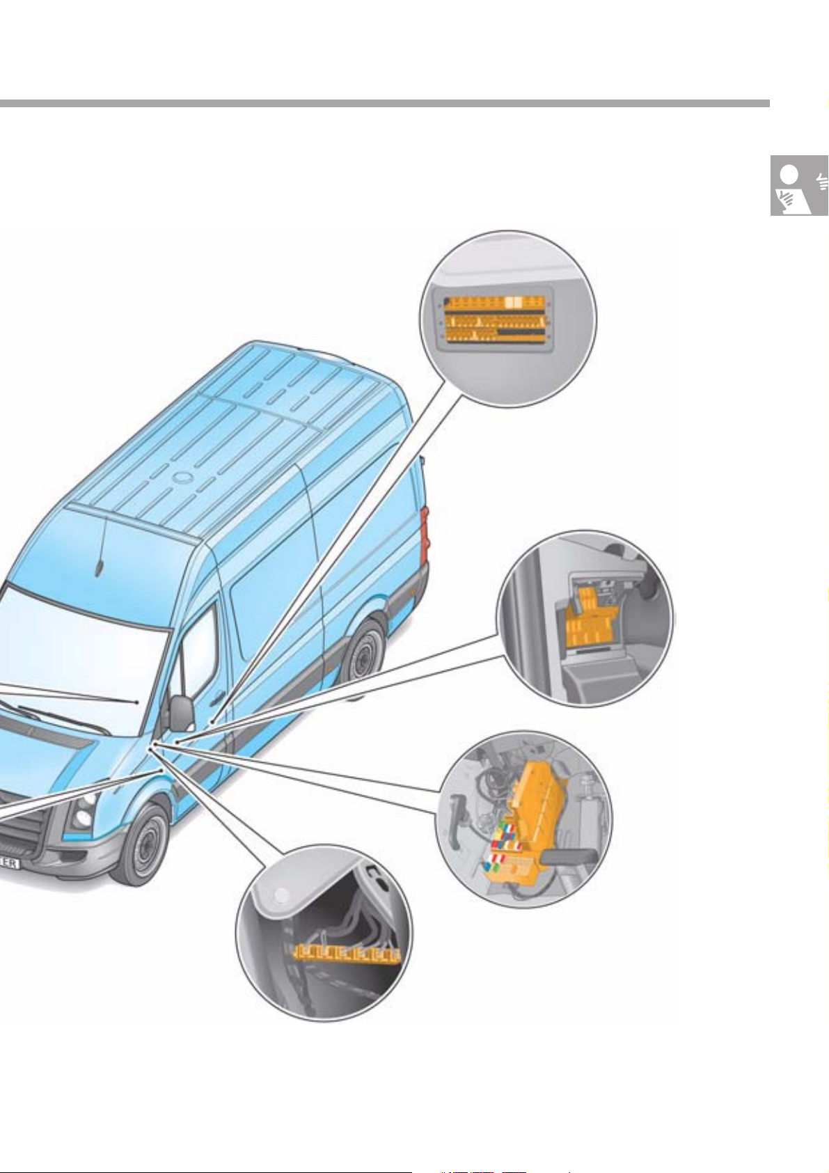
Fuse holder D (SD),
beneath the driver's seat
Fuse holder B (SB),
left A pillar
Junction box 1 for bus systems,
beneath the front left dash panel
Fuse holder C (SC),
on the left A pillar
S370_002
7
Introduction
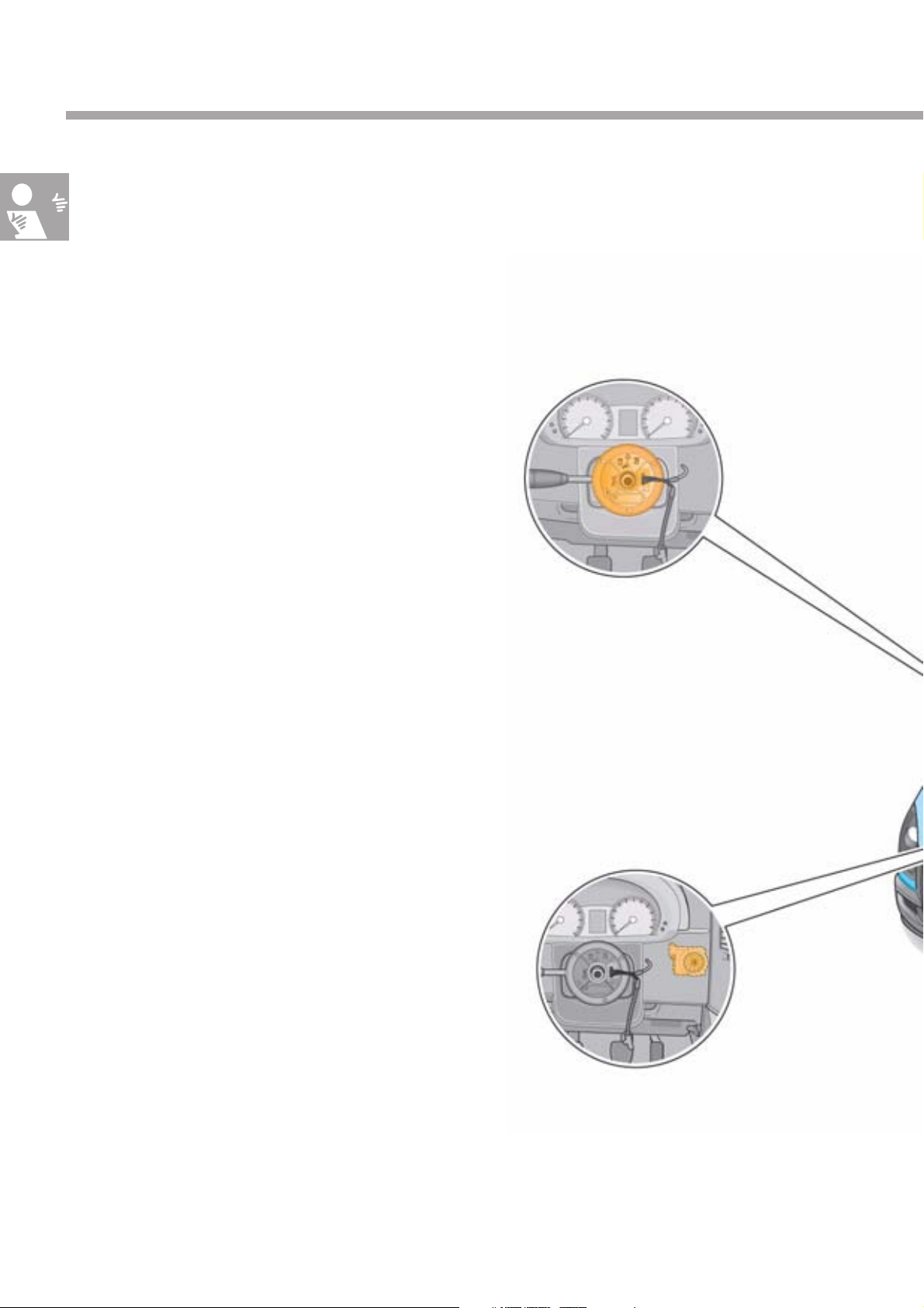
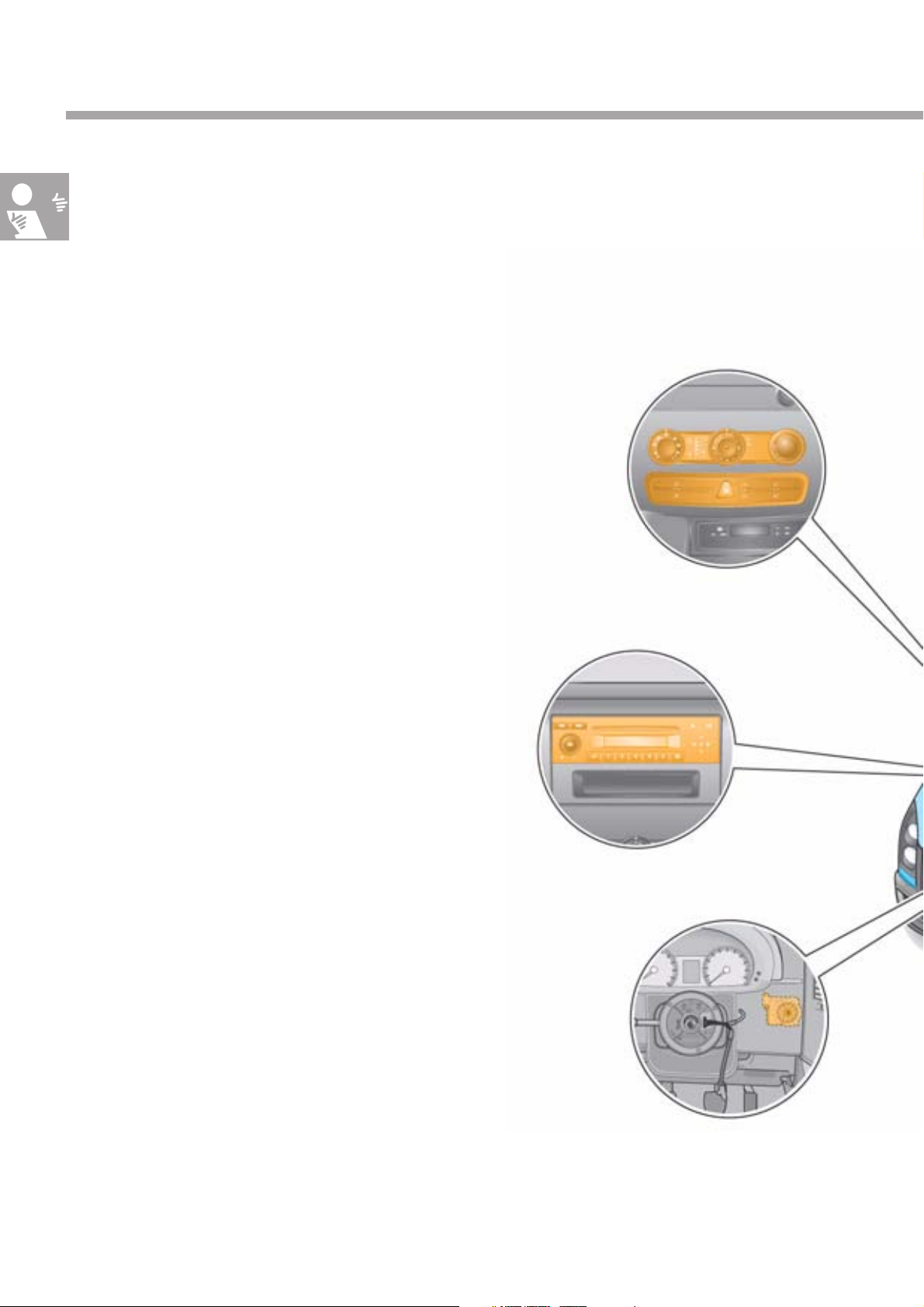
Installation locations of the control units in the CAN drive data bus
Control units and installation
locations
The adjacent illustration shows the control units which
take part in CAN drive data bus data communication
and their installation locations.
Data are transmitted at a speed of
500 kbit/s. Transmission is carried out via the
CAN high cable and the CAN low cable.
CAN high cables are green/white and the
CAN low cables are green.
To ensure reliable data transmission,
the CAN cables are twisted together.
The CAN drive data bus is not 1-wire-capable;
if a CAN cable fails, no data transmission is possible.
Steering column electronics control
unit J527,
on the steering column
Electronic ignition lock D9,
on the right next to the steering wheel
8
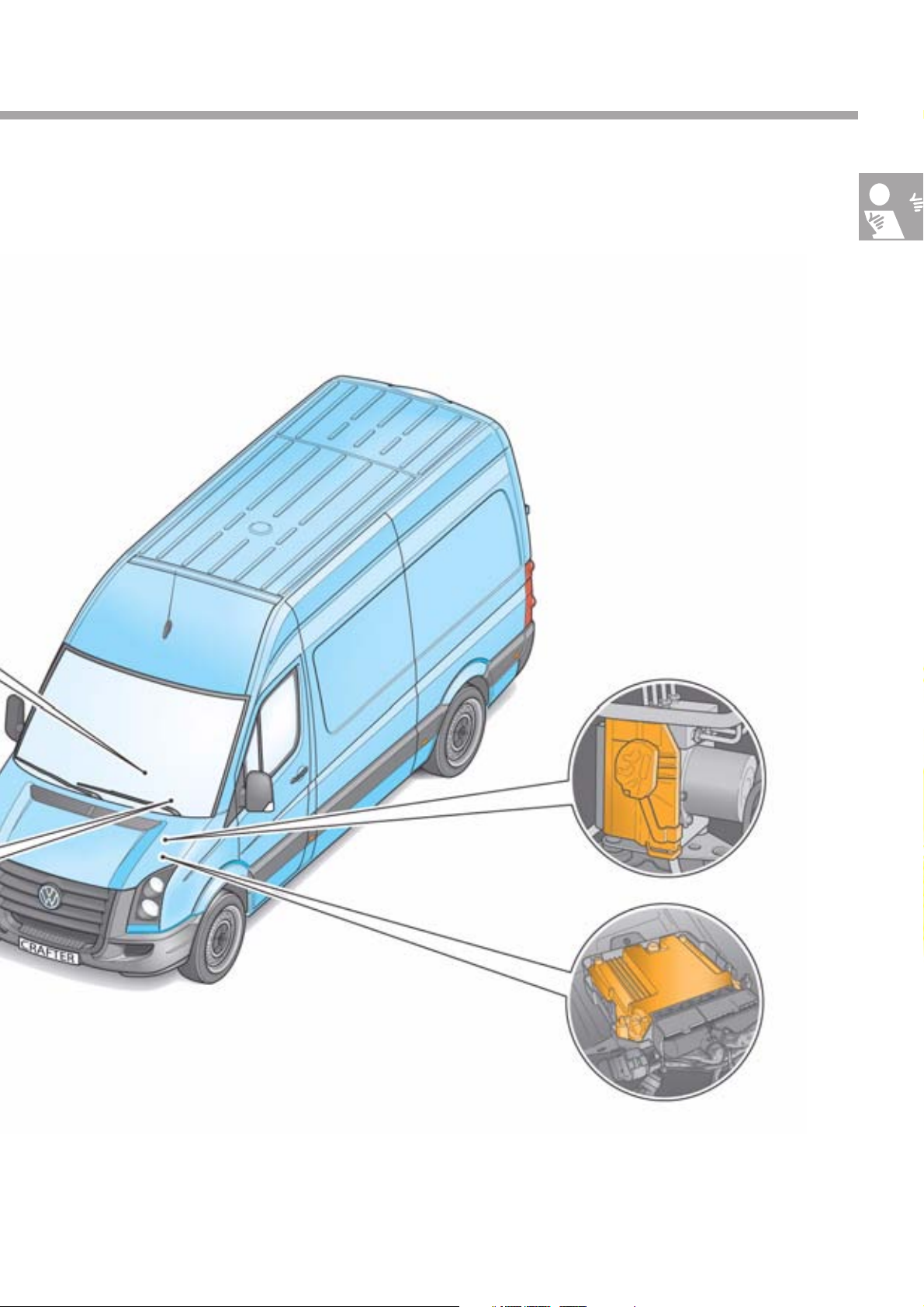
ABS control unit J104,
on the left in the engine compartment
Engine control unit J623,
on the left in the engine
compartment
S370_004
9
Introduction
Installation locations of the control units in the CAN convenience
data bus
Control units and installation
locations
The adjacent illustration shows the control units which
take part in CAN convenience data bus data
communication and their installation locations.
Data are transmitted at a speed of
83.3 kbit/s. Transmission is carried out via the CAN
high cable and the CAN low cable.
CAN high cables are brown/red and the CAN low
cables are brown.
To ensure reliable data transmission, the CAN
cables are twisted together.
Air conditioning system control unit J301,
in centre of dash panel
The CAN convenience data bus is 1-wire-capable;
if a CAN cable fails, data transmission remains
possible.
Control unit for middle of dash panel J819,
in centre of dash panel
Radio R/control unit with display for radio and
navigation J503 *,
in centre of dash panel
10
* Acts as the interface for the MOST
infotainment data bus
Electronic ignition lock D9,
on the right next to the steering
wheel
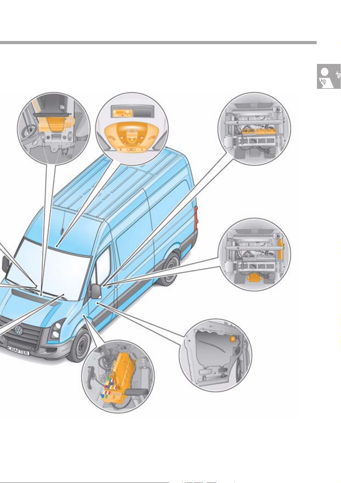
Airbag control unit J234,
beneath the centre console
Auxiliary heater control unit J364,
in moulded headlining near to the interior mirror
Roof electronics
control unit J528,
in moulded
headlining near to
the interior mirror
Trailer detector control
unit J345,
beneath the front left seat
Control unit for programmable
special functions J820,
beneath the front left seat
Parking aid control unit J446,
beneath the front left seat
Onboard supply control unit J519,
on the left A pillar
Tyre pressure monitor control unit J502,
beneath the front left seat
Driver door control unit J386,
in the front left door
S370_003
11
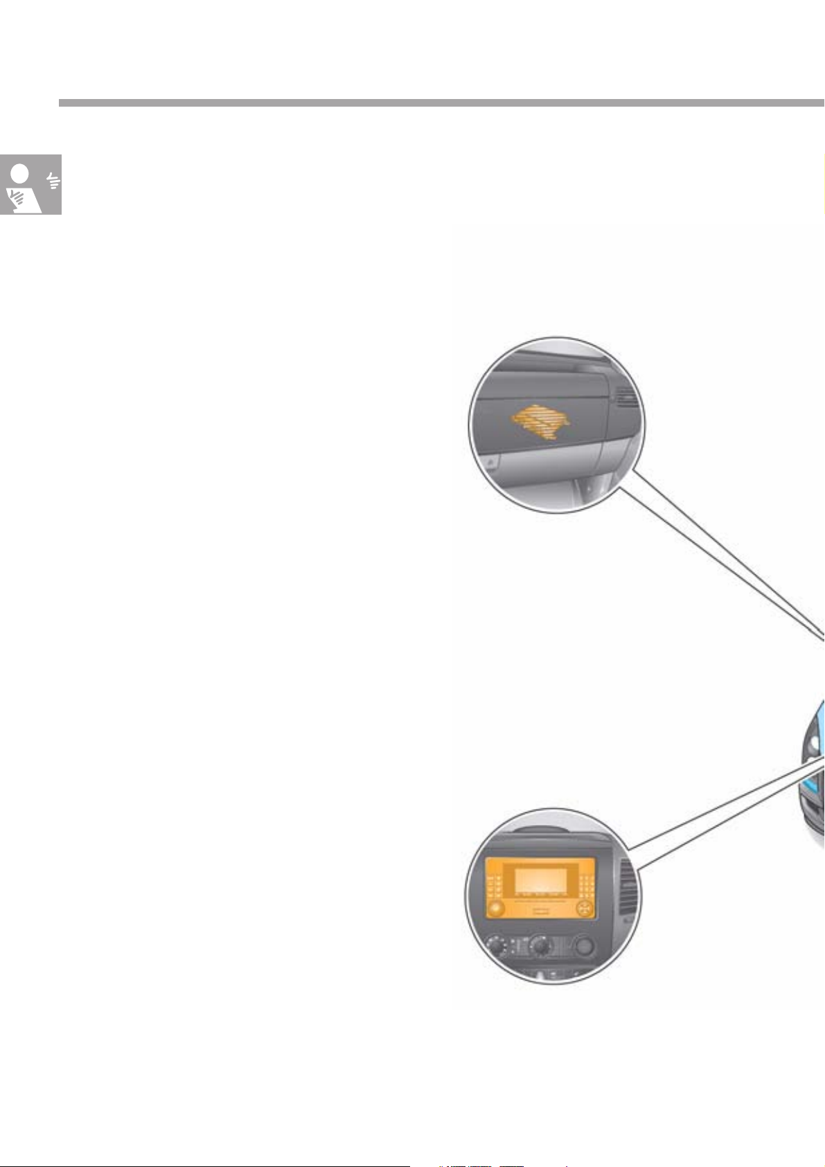
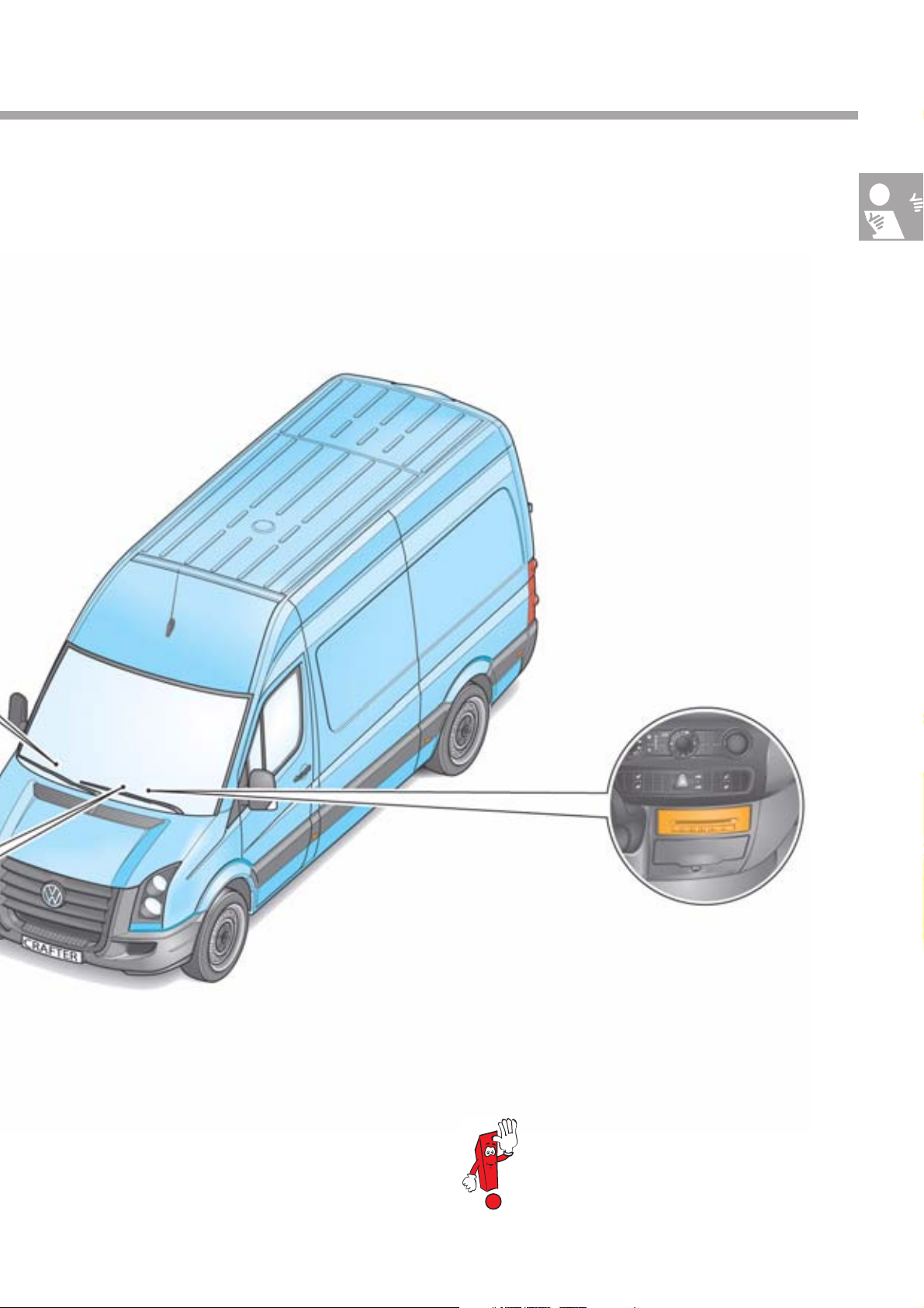
Introduction
Installation locations of the control units in the MOST infotainment
data bus
Control units and installation
locations
Besides the familiar CAN data bus systems,
the Volkswagen Crafter is also equipped with an
optical data bus system.
This data bus system has been named according
to the "Media Oriented Systems Transport" (MOST)
cooperation.
This co-operation has been established by various car
manufacturers, their suppliers and software
companies in order to implement a standardised
system for fast data transmission.
The optical MOST data bus is used to exchange data
between the radio/control unit with display for radio
and navigation, the CD changer and the mobile
telephone operating electronics control unit by means
of light waves.
In comparison with radio waves, light waves have
very short wavelengths, do not generate
electromagnetic interference waves, are
simultaneously insensitive to these and have
a significantly higher data transmission rate than
electronic data bus systems.
On routing, the radius of the fibre optical cable must
be at least 25 mm.
Mobile telephone operating
electronics control unit J412,
behind the glove box
12
Control unit with display unit for radio and
navigation J503/radio R,
in centre of dash panel
CD changer R41,
centre of vehicle interior
S370_071
During diagnosis, please observe the
Guided Fault Finding instructions.
13
Vehicle electrical system
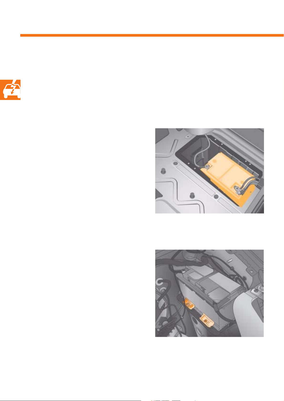
Batteries
Equipment
The Volkswagen Crafter can be optionally equipped
with a dual-battery vehicle electrical system; in this
case, a starter and a vehicle electrical supply battery
are installed.
Starter battery
The vehicle electrical system's standard 12 V vehicle
voltage is supplied by the maintenance-free starter
battery. The starter battery is installed in the covered
battery recess in front of the driver's seat (left-hand
drive vehicle) or the front passenger's seat (right-hand
drive vehicle).
A vent pipe emerges into the open air from the recess.
Vehicle electrical system battery
To supply high-current, body-side consumers,
a second battery, located on the left of the engine
compartment, is available in addition to the starter
battery (left-hand drive vehicles only). This second
battery is not intended as a starter battery.
By supplying the high-current consumers, it is instead
intended to protect the starter battery from discharge,
thereby maintaining the vehicle's ability to start.
S370_049
S370_050
14
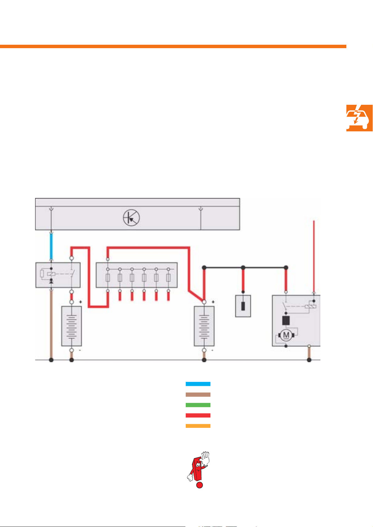
Functional diagram
The second battery A1 is only available in
combination with the battery isolation relay J7.
This prevents battery A from being drained by
consumers which are connected to the second battery.
At the same time, drainage of the second battery
by the standard consumers is prevented.
J519
J7 SA
A1 A
Legend
ABattery
A1 Second battery
BStarter
J7 Battery isolation relay
J519 Onboard supply control unit
SA Fuse holder A
TV32 Jump start connection
SSSSSS
TV32
B
S370_051
Signal output
Ground
Signal input
Positive
CAN data bus cable
The signal cable colours shown in the illustration
apply to all subsequent functional diagrams.
15
Vehicle electrical system
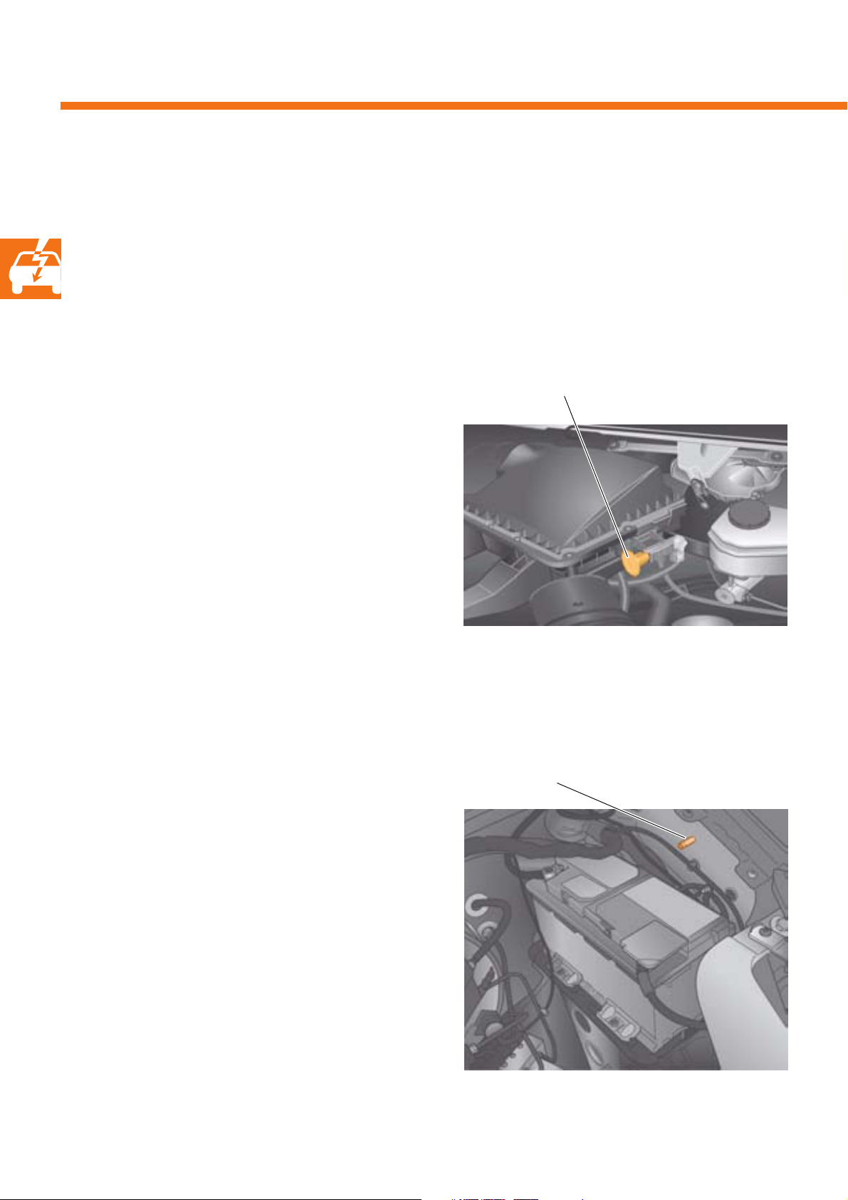
Jump start connections
Equipment
The Volkswagen Crafter is equipped with a positive
and a negative connection for jump-starting and for
charging the battery.
Positive jump start connection
To connect a jump-starting cable or a battery charger,
a connection point for the positive cable is located on
the left-hand side of the air filter housing in the
engine compartment.
Negative jump start connection
Jump start connection
S370_052
Jump start connection
16
To connect a jump-starting cable or a battery charger,
a connection point for the negative cable is located
on the left-hand wing in the engine compartment.
S370_053
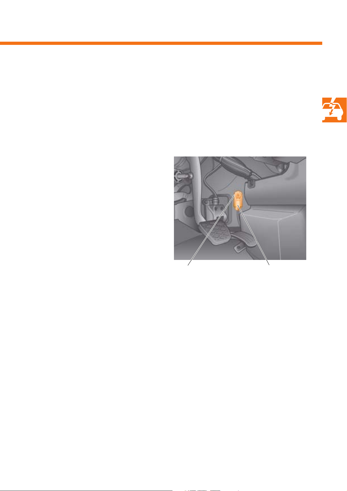
Negative main connection
The optional, main connection for the battery
negative cable is located on the right next to the
accelerator pedal.
The connection and the ground bolt can be separated
by pulling the red actuation tab.
This enables the battery to be isolated from the
vehicle electrical system if necessary or prescribed for
repair work.
Main connection Actuation tab
S370_054
17
Vehicle electrical system
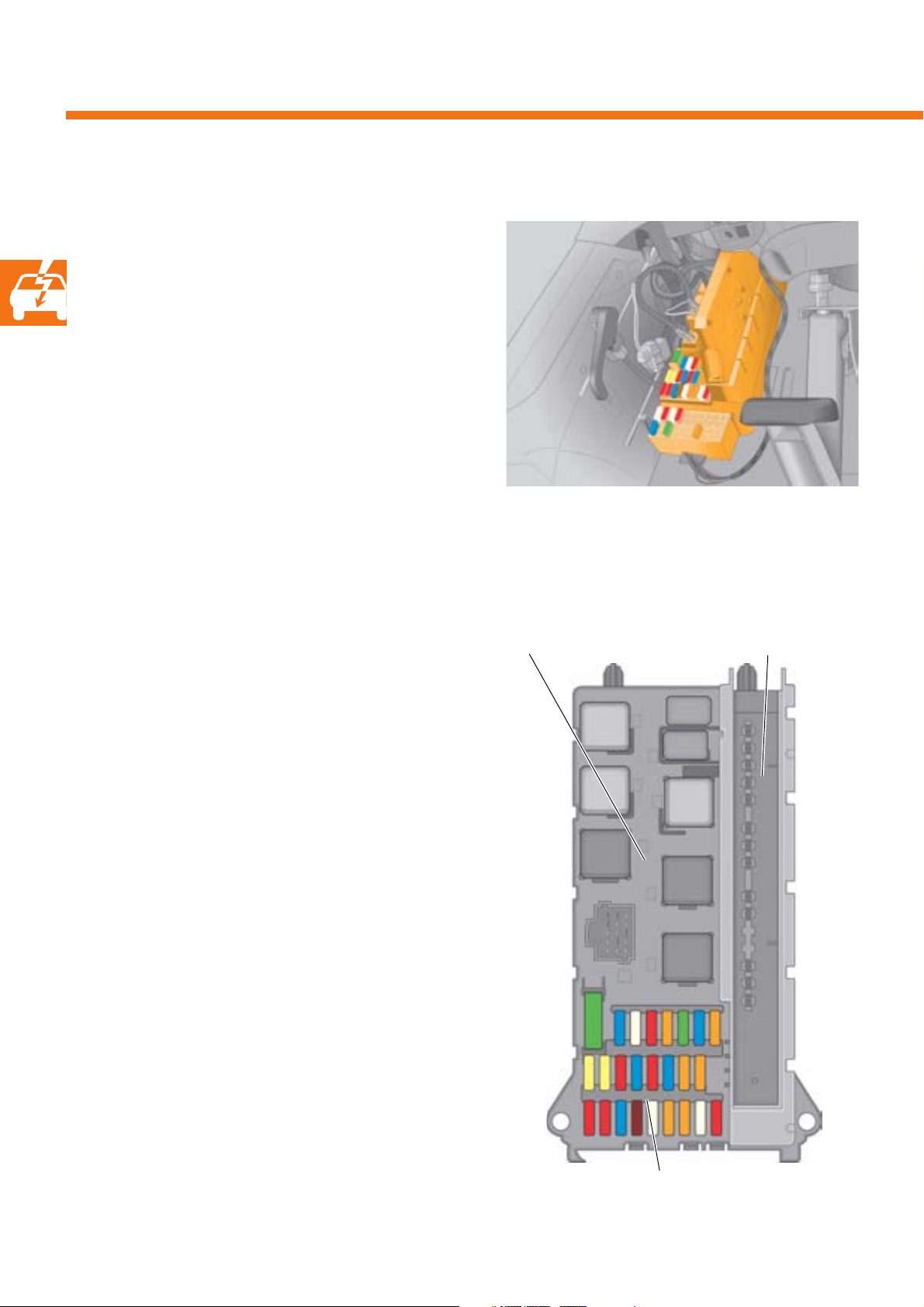
Onboard supply control unit
Installation location
The onboard supply control unit (OBSCU) J519 is
located, together with the fuse and relay box, on
the left of the vehicle interior in the footwell beneath
the instrument panel.
S370_006
Variants
It is available in the following variants:
-Standard
- Low line
-Mid line and
- High line
The different variants offer various functions.
Relay box
Onboard supply control unit
18
Fuse box
S370_007
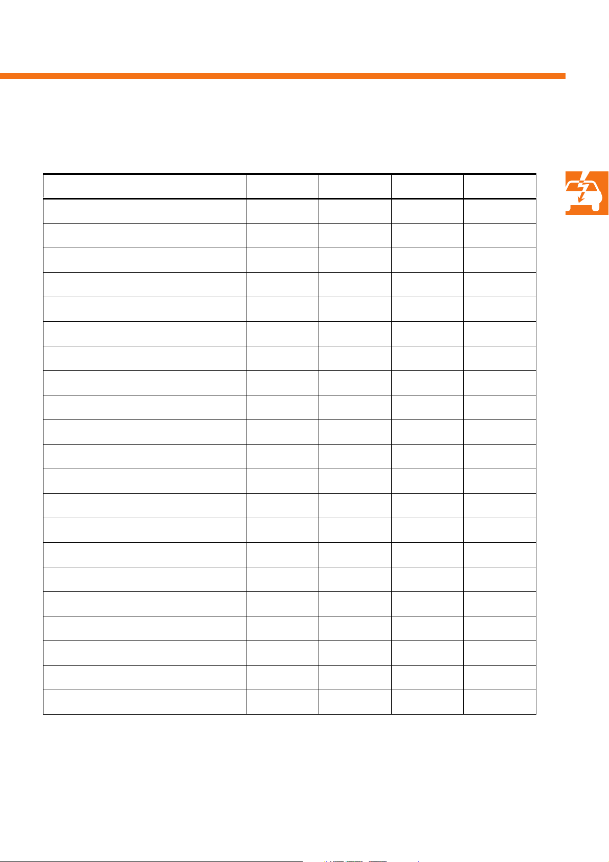
Functions
Function Standard Low line Mid-line High-line
Exterior light control system with bulb monitoringXXXX
High-level brake light X X
Fog lights XX
Turn signal actuation XXXX
Interior light control system XXXX
Interior convenience light X
Windscreen wiper and washer systemXXXX
Rear window wiper and washer system X X
Heated rear window X X
Heated windscreen X
Central locking: Sliding door, hinged rear door X X X
Central locking: 2nd sliding door X X
Rotary light switch input XXXX
Sensor signal and switch input XXXX
Vent windows X
Headlight washer system X X
Auxiliary turn signal module X X
Alarm function XXXX
ATA function XXXX
Central locking: Front passenger door XXXX
Window regulator: Front passenger door XXXX
19
Vehicle electrical system
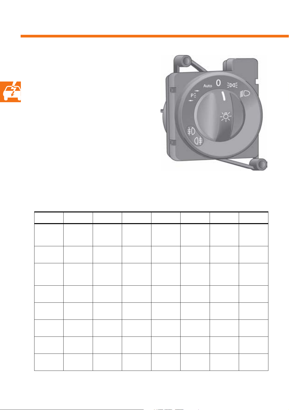
Light switch
Function
The light switch E1 is responsible for actuating the
exterior light functions. The onboard supply control
unit reads in the signals from the voltage-coded light
switch directly.
The signals for the turn signal and main beam
functions are transmitted from the steering column
electronics control unit via the CAN drive data bus
and the CAN convenience data bus.
S370_005
Variants
The light swicth is available in eight different variants.
Variant 1 Variant 2 Variant 3 Variant 4 Variant 5 Variant 6 Variant 7 Variant 8
Off Autom.
driving
lights
Side light Off Side light Off Right
Dipped
beam
Rear fog
light
Side light Dipped
Dipped
beam
Rear fog
light
Off Autom.
driving
lights
Side light Off Autom.
beam
Rear fog
light
Fog light Rear fog
Dipped
beam
light
Left parking
light
parking light
Side light Off Side light Off
Dipped
beam
Left parking
light
Right
parking light
driving
lights
Side light Dipped
Left parking
light
Right
parking light
Off Autom.
beam
Left parking
light
Right
parking light
driving
lights
Side light
20
Fog light Rear fog
light
Dipped
beam
Rear fog
light
Rear fog
light
Fog light Rear fog
Dipped
beam
light
Fog light
Turn signal control system
Function description
The onboard supply control unit is the master for the
turn signal function and carries out the various turn
signal functions. It receives all requests to actuate the
turn signals, prioritises these and is the only control
unit to implement a turn signal pulse on the CAN data
bus. All of the other involved control units evaluate
this turn signal pulse.
Turn signal actuation priority
The turn signals are actuated according to the
following piority:
● 1 Airbag hazard warning flashing
● 2 Special alarm flashing
● 3 Direction indication or hazard warning flashing
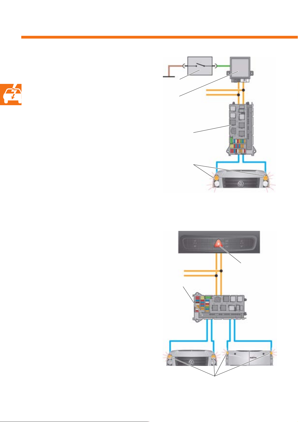
Airbag hazard warning flashing
In the event of airbag deployment, the airbag control
unit transmits a CAN message to the onboard supply
control unit. The hazard warning flashing function is
then triggered.
Electronic ignition lock D9
● 4 ATA alarm flashing
● 5 Central locking feedback flashing
This function is deactivated by actuating the hazard
warning lights button (E229) once or by switching the
ignition off, on and off again.
Airbag control
unit J234
Turn signal bulbs
Onboard supply control unit J519
S370_008
21
Vehicle electrical system
Special alarm flashing
The control unit for programmable special functions
can request alarm flashing with a pre-specified on/off
phase from the onboard supply control unit.
Switch
Depending on the way in which the control unit for
programmable special functions is programmed, the
following lighting facilities can be actuated in the
event of special alarm flashing:
- Main beam,
- Fog lights and
-Turn signals
The special alarm flashing function is used,
e.g. in emergency vehicles.
Hazard warning flashing
The onboard supply control unit receives the hazard
warning flashing signal from the control unit for
middle of dash panel J819, which reads in the signals
from the hazard warning lights button E229. The
onboard supply control unit then actuates all turn
signals.
No bulb monitoring is carried out during hazard
warning flashing. The hazard warning flashing
function is always operational.
Control unit for
programmable special
functions
Onboard supply control unit
Bulbs
S370_009
Control unit for middle of dash panel
Hazard warning lights
button E229
Onboard supply control
unit J519
22
Turn signal bulbs
S370_010
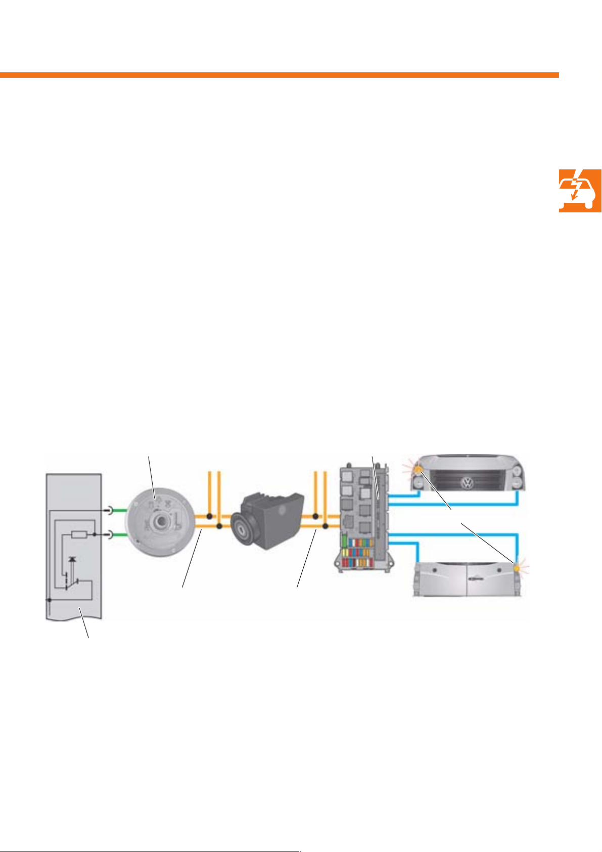
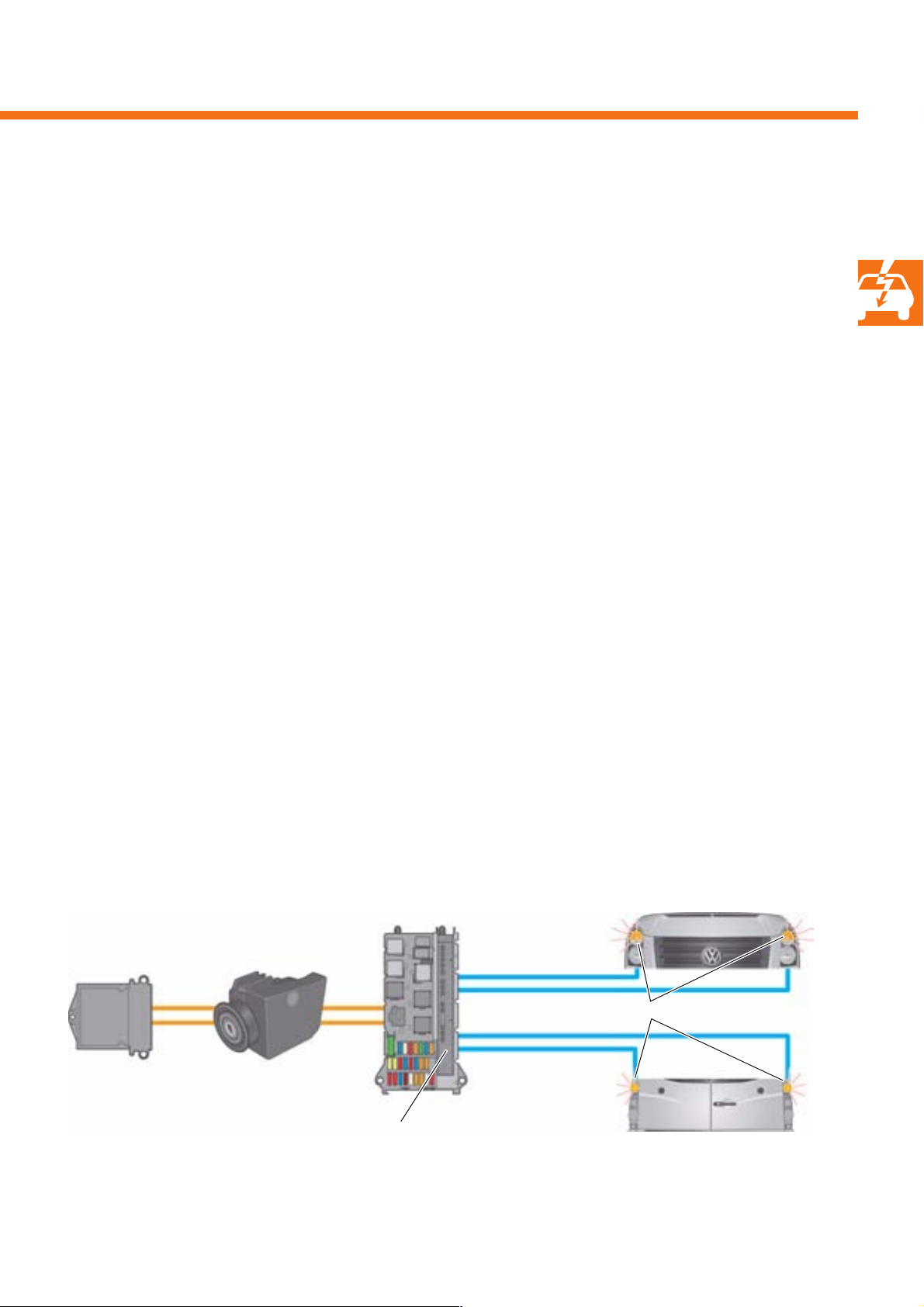
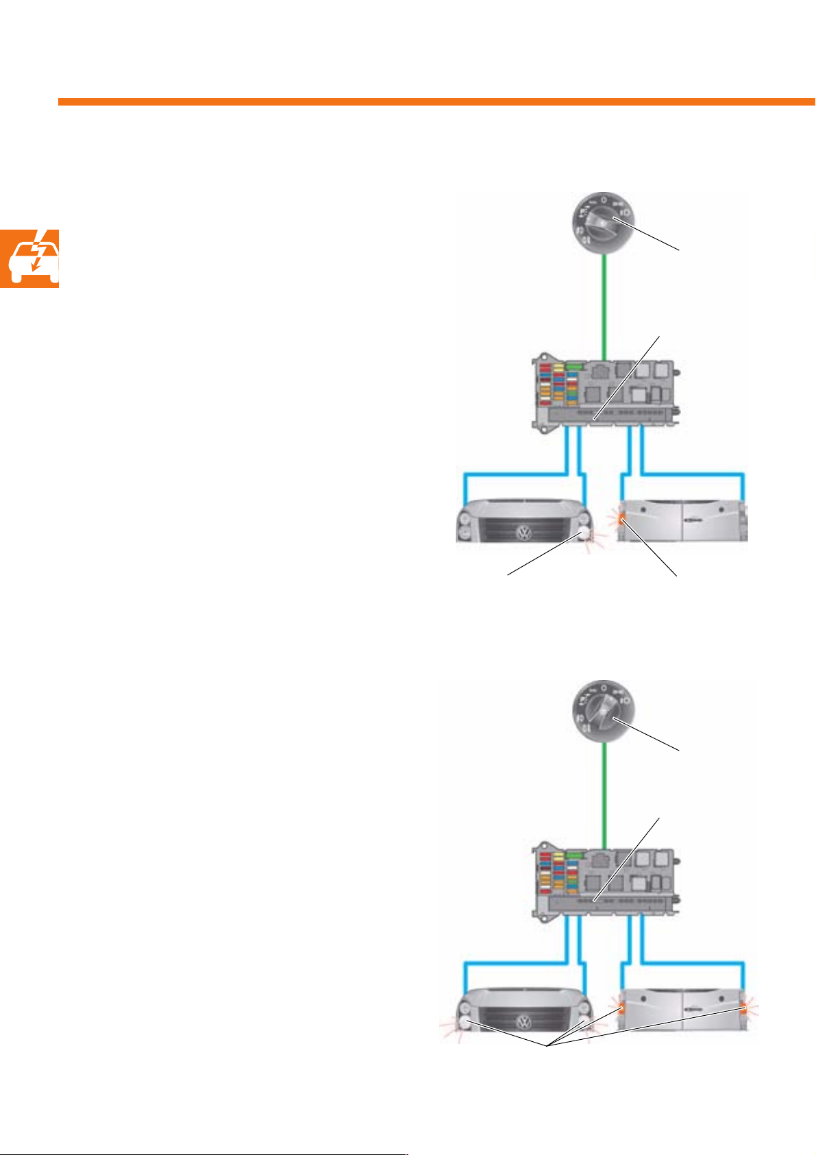
Direction indication
The signal for direction indication is received by the
onboard supply control unit from the steering column
electronics control unit J527, which reads in the signals
from the turn signal switch E2 in voltage-coded form.
The electronic ignition lock (EIL) D9 transfers the
signals from the CAN drive data bus to the CAN
convenience data bus. The onboard supply control
unit actuates the turn signal bulbs as requested.
During direction indication, the turn signal bulbs are
monitored for bulb failure.
The bulbs' flashing frequency is doubled in the event
of bulb failure. Actuation of the turn signal warning
lamps is carried out via the CAN convenience data
bus and the control unit in the dash panel insert. The
direction indication function is only active in the case
of "terminal 15 on".
Steering column electronics control unit J527
Turn signal switch E2
Onboard supply control unit J519
Turn signal bulbs, right
CAN drive data bus CAN convenience data bus
S370_011
23
Vehicle electrical system
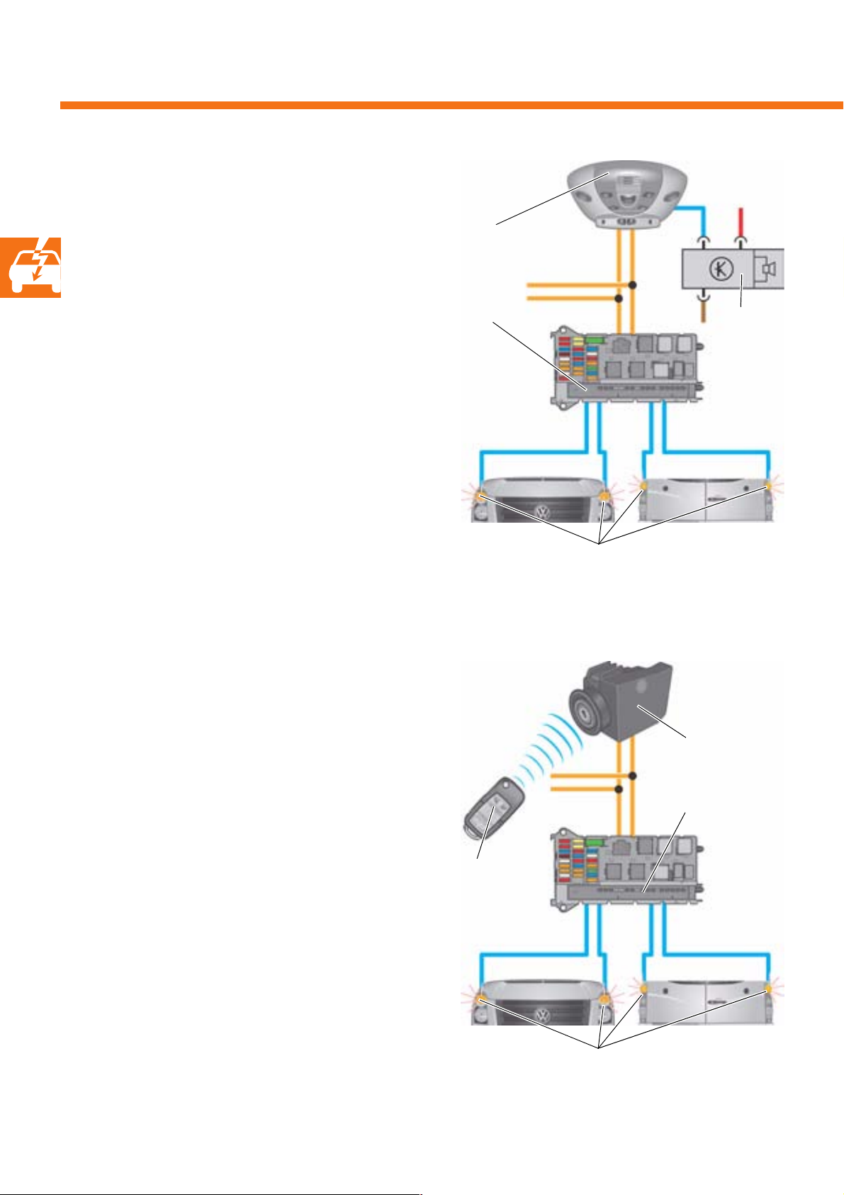
ATA alarm flashing
The ATA alarm flashing function is active if no
authorised key is located in the electronic
ignition lock (EIL).
The alarm is output via the alarm horn H12 and the
turn signals.
In this case, the roof electronics control unit transmits
a request to the onboard supply control unit via the
CAN convenience data bus. Bulb monitoring is not
carried out during ATA alarm flashing.
Roof electronics
control unit
Onboard supply control
unit
Alarm horn
Central locking feedback flashing
Unlocking the vehicle is indicated by all of the turn
signals' flashing twice. Locking the vehicle is indicated
by all of the turn signals' flashing once.
The request for central locking feedback flashing is
transmitted by the electronic ignition lock via the CAN
convenience data bus. This function is only active if no
authorised key is located in the electronic ignition
lock.
S370_012
Turn s i gnal s
Electronic
ignition lock
Onboard supply control
unit
Radio
remote control
24
S370_013
Turn s i gnals
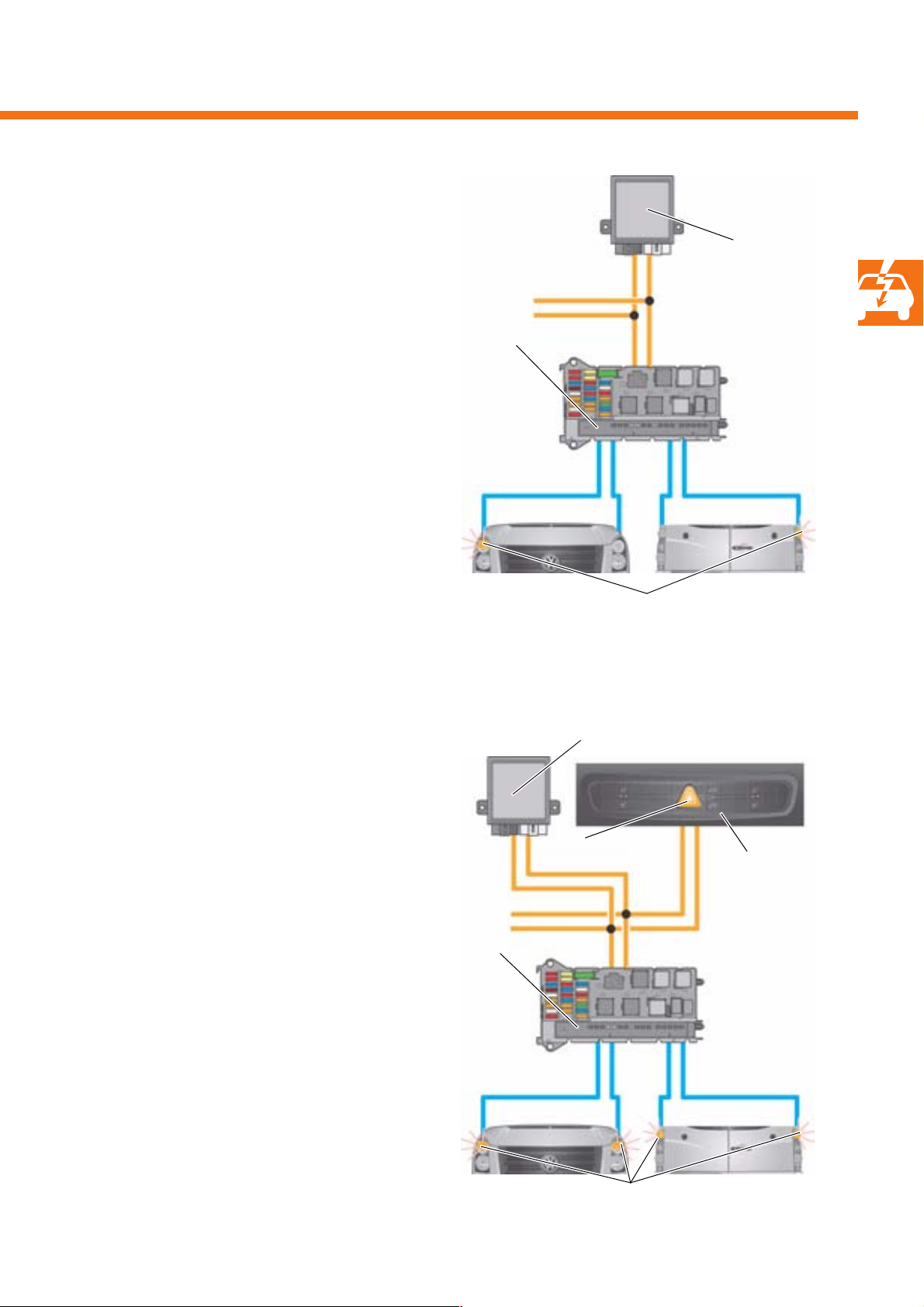
Special direction indication
The control unit for programmable special functions is
able to request direction indication from the onboard
supply control unit. The onboard supply control unit
handles this request like a request from the steering
column electronics control units, although these
requests have priority.
The control unit for programmable special functions
does not send a request, or ends its request, as soon
as it detects a request for direction indication from the
steering column electronics control unit.
Control unit for
programmable
special functions
Onboard supply control
unit
S370_014
Turn sig n a l s
Special hazard warning flashing
The control unit for programmable special functions is
able, like the control unit for middle of dash panel,
to request hazard warning flashing from the onboard
supply control unit.
It withdraws its request as soon as it detects a request
from the control unit for middle of dash panel.
This function is deactivated either by the control unit
for programmable special functions or by actuating
the hazard warning lights button.
Control unit for programmable special functions
Hazard warning
lights button
Onboard
supply
control
unit
Control unit for
middle of dash
panel
Turn sig n a l s
S370_015
25
Vehicle electrical system
Lighting
Parking light
The left or right side light bulbs and the left or right
tail light bulbs are actuated by the onboard supply
control unit.
Light switch
The request to switch on the parking lights comes
directly from the light switch.
The parking light function is active if no authorised
key is located in the EIL.
Bulb monitoring is carried out when the parking light
function is on.
Side light and tail light
Onboard supply
control unit
S370_016
Left side light bulb Left tail light bulb
26
The left and right side and tail light bulbs are
actuated by the onboard supply control unit.
The request to switch on comes directly from the light
switch. The side and tail lights can also be switched on
if the ignition key has been removed, in which case an
acoustic signal is emitted.
Side light and tail light bulbs
Light switch
Onboard supply
control unit
S370_017
 Loading...