How it Works
Log In / Sign Up
0
My Files
0
My Downloads
329214
History
Account Settings
Log Out
Buy Points
How it Works
FAQ
Contact Us
Questions and Suggestions
Users
Volkswagen
Loading...
C
Cabriolet 26-34 Esqvw23a
Cabriolet 30-34 Esqvw24
Cabriolet 33-34 Esqvw25b
CALIFORNIA
2
Caravelle
2
CC 2010
CC 2012
CC 2013
Citigo
Corrado 1990
CQ-JV1060
Crafter
Crafter 2014
E
E Golf 2015
Egolf 2016
EOS 2006
2
EOS 2012
F
FOX
FOX 2004
4
G
Golf
5
Golf 12-18 esqvw7
Golf 1989
Golf 1992
Golf 1994
Golf 1996
Golf 1998
Golf 1998 2000
Golf 2004
5
Golf 2005
2
Golf 2006
Golf 2007
3
Golf 2009
2
Golf 2011
Golf 2012
Golf 2013
Golf 2016
Golf 2018
Golf 4-18 esqvw1D
GOLF 5 2005
GOLF 6
3
Golf 7
4
Golf 9-18 esqvw4
Golf E
GOLF ESTATE
Golf GTI
GOLF IV
2
Golf Jetta 1999 2005
Golf Plus 2005
9
Golf Plus 2006
Golf Plus 2009
3
Golfsportwagen 2016
Golf V
Golf Variant 1992
Golf Variant 1998
Golf Variant 2007
9
Golf Variant 2008
Golf Variant 2010
7
Gti 2011
Gti 2012
Gti 2013
I
Iltis 1979
J
Jetta 1999 2000
Jetta 2004
Jetta 2005
8
Jetta 2006
2
Jetta 2011
2
Jetta 2012
Jetta 2014
Jetta 2015
Jetta 2016
Jetta 2018
Jetta 2019
Jetta Gli 2013
Jetta Gli 2014
Jetta Hybrid 2015
Jetta Sportwagen Changing Light Bulbs 2013
Jetta Sportwagen Engine Oil 2013
Jetta Sportwagen Tires And Wheels 2013
K
Karmann Ghia 1973
Karmann Ghia 1974
L
LT 1976 1987
LT 1989
Lupo
Lupo 1999
M
MFD RADIO NAVIGATION SYSTEM
Multivan T5
N
New Beetle
3
New Beetle 2008
P
Passat 1990
Passat 1991
Passat 1997
Passat 1998 2005
PASSAT 2001
Passat 2006
Passat 2009
Passat 2013
Passat 2014
Passat 2016
2
Passat 2017
Passat 2018
Loading...
Loading...
Nothing found
Golf V
User Manual
2326 pgs
49.85 Mb
3
Table of contents
Loading...
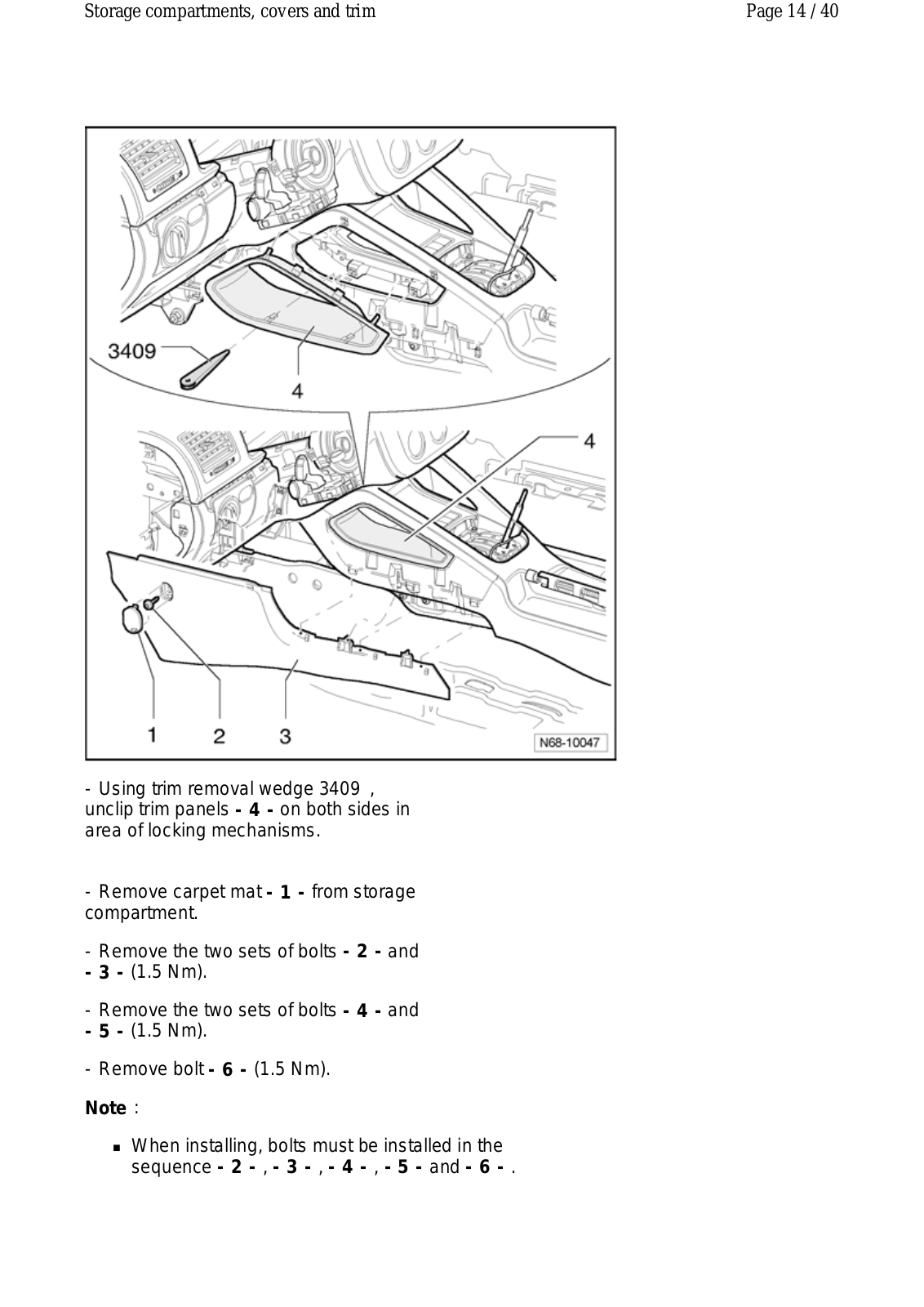
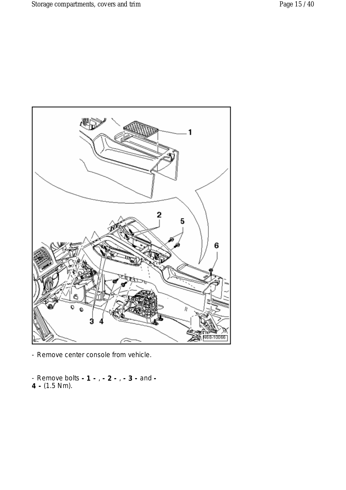
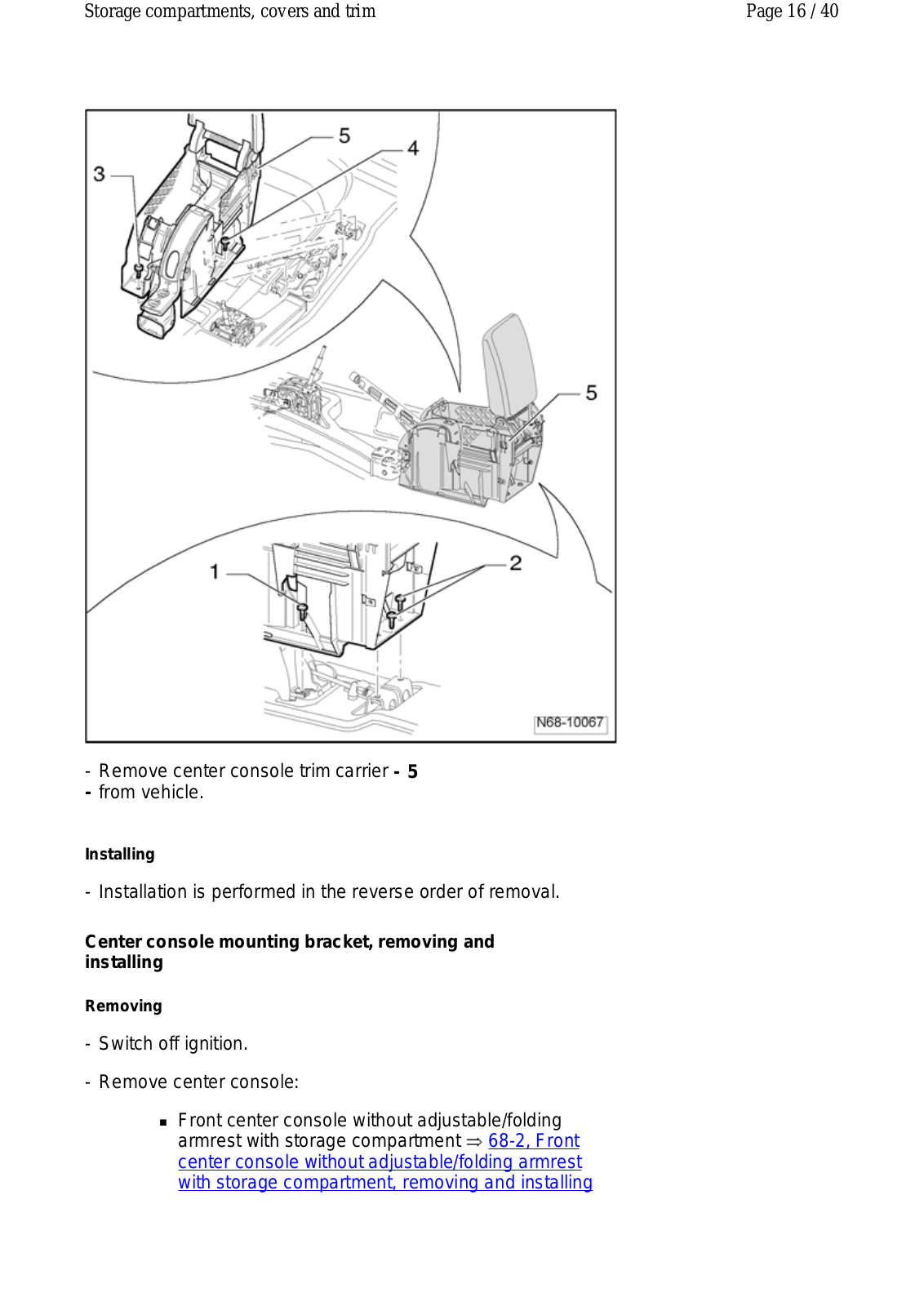
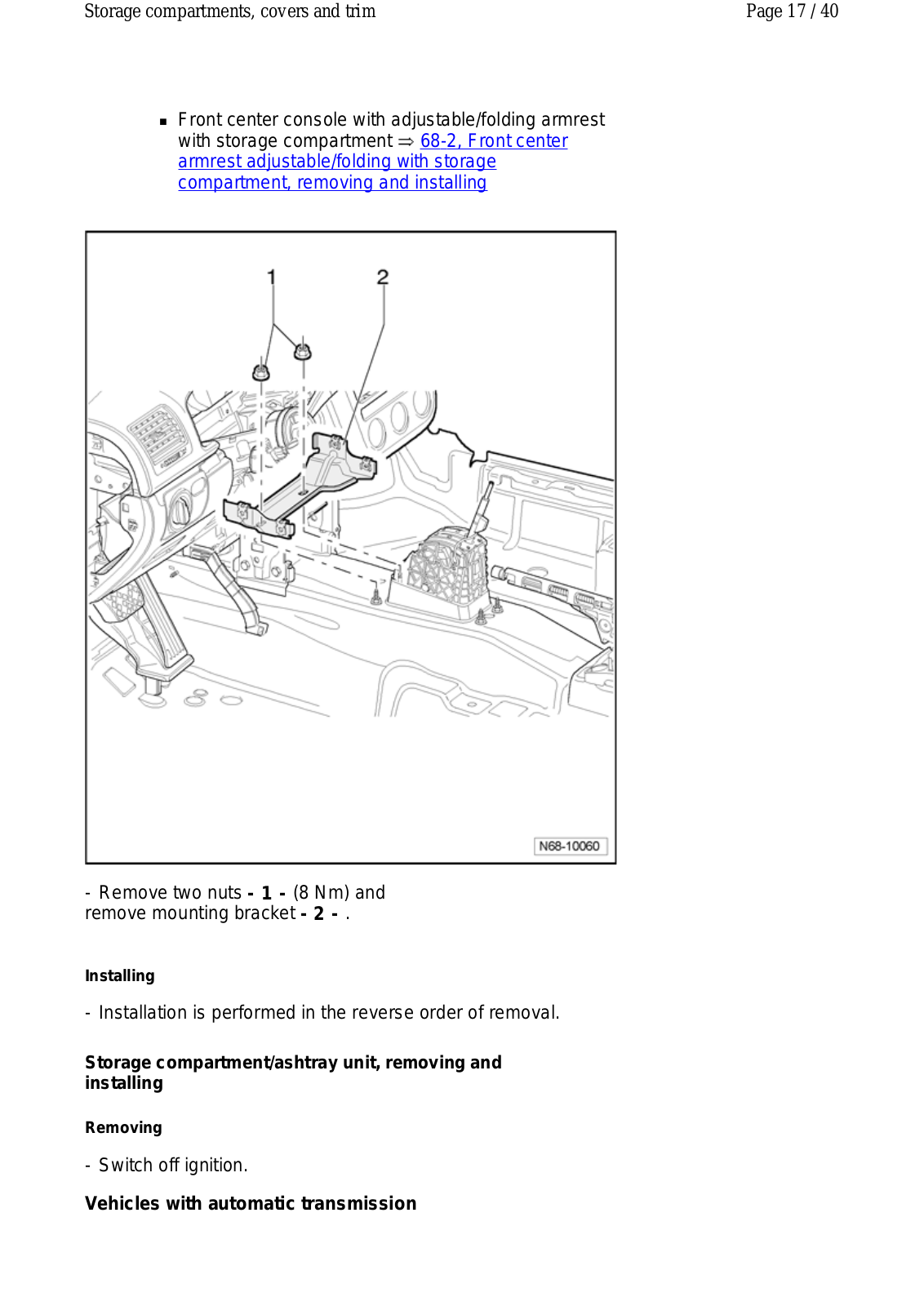
Volkswagen Golf V User Manual
...
Volkswagen User Manual
Download
Loading...
+
2296
hidden pages
Unhide
You need points to download manuals.
1 point = 1 manual.
You can buy points or you can get point for every manual you upload.
Buy points
Upload your manuals
 Loading...