


Volkswagen Eos 2006 User Manual
P
r
o
t
e
c
t
e
d
b
y
c
o
p
y
r
i
g
h
t
.
C
o
p
y
i
n
g
f
o
r
p
r
i
v
a
t
e
o
r
c
o
m
m
e
r
c
i
a
l
p
u
r
p
o
s
e
s
,
i
n
p
a
r
t
o
r
i
n
w
h
o
l
e
,
i
s
n
o
t
p
e
r
m
i
t
t
e
d
u
n
l
e
s
s
a
u
t
h
o
r
i
s
e
d
b
y
V
o
l
k
s
w
a
g
e
n
A
G
.
V
o
l
k
s
w
a
g
e
n
A
G
d
o
e
s
n
o
t
g
u
a
r
a
n
t
e
e
o
r
a
c
c
e
p
t
a
n
y
l
i
a
b
i
l
i
t
y
w
i
t
h
r
e
s
p
e
c
t
t
o
t
h
e
c
o
r
r
e
c
t
n
e
s
s
o
f
i
n
f
o
r
m
a
t
i
o
n
i
n
t
h
i
s
d
o
c
u
m
e
n
t
.
C
o
p
y
r
i
g
h
t
b
y
V
o
l
k
s
w
a
g
e
n
A
G
.
Service
Workshop Manual
Eos 2006 ➤
Golf 2004 ➤
Golf Plus 2005 ➤
Touran 2003 ➤
Brake systems
Edition 05.2008
Service Department. Technical Information

P
r
o
t
e
c
t
e
d
b
y
c
o
p
y
r
i
g
h
t
.
C
o
p
y
i
n
g
f
o
r
p
r
i
v
a
t
e
o
r
c
o
m
m
e
r
c
i
a
l
p
u
r
p
o
s
e
s
,
i
n
p
a
r
t
o
r
i
n
w
h
o
l
e
,
i
s
n
o
t
p
e
r
m
i
t
t
e
d
u
n
l
e
s
s
a
u
t
h
o
r
i
s
e
d
b
y
V
o
l
k
s
w
a
g
e
n
A
G
.
V
o
l
k
s
w
a
g
e
n
A
G
d
o
e
s
n
o
t
g
u
a
r
a
n
t
e
e
o
r
a
c
c
e
p
t
a
n
y
l
i
a
b
i
l
i
t
y
w
i
t
h
r
e
s
p
e
c
t
t
o
t
h
e
c
o
r
r
e
c
t
n
e
s
s
o
f
i
n
f
o
r
m
a
t
i
o
n
i
n
t
h
i
s
d
o
c
u
m
e
n
t
.
C
o
p
y
r
i
g
h
t
b
y
V
o
l
k
s
w
a
g
e
n
A
G
.
Service
List of Workshop Manual Repair GroupsList of Workshop Manual
Repair GroupsList of Workshop Manual Repair Groups
Re pa ir G ro up
00 - Technical data
45 - Anti-lock brake system
46 - Brakes - mechanism
47 - Brakes - hydraulics
Technical information should always be available to the foremen and mechanics, because their
careful and constant adherence to the instructions is essential to ensure vehicle road-worthiness and
safety. In addition, the normal basic safety precautions for working on motor vehicles must, as a
matter of course, be observed.
All rights reserved.
No reproduction without prior agreement from publisher.
Copyright © 2010 Volkswagen AG, Wolfsburg K0058970520

P
r
o
t
e
c
t
e
d
b
y
c
o
p
y
r
i
g
h
t
.
C
o
p
y
i
n
g
f
o
r
p
r
i
v
a
t
e
o
r
c
o
m
m
e
r
c
i
a
l
p
u
r
p
o
s
e
s
,
i
n
p
a
r
t
o
r
i
n
w
h
o
l
e
,
i
s
n
o
t
p
e
r
m
i
t
t
e
d
u
n
l
e
s
s
a
u
t
h
o
r
i
s
e
d
b
y
V
o
l
k
s
w
a
g
e
n
A
G
.
V
o
l
k
s
w
a
g
e
n
A
G
d
o
e
s
n
o
t
g
u
a
r
a
n
t
e
e
o
r
a
c
c
e
p
t
a
n
y
l
i
a
b
i
l
i
t
y
w
i
t
h
r
e
s
p
e
c
t
t
o
t
h
e
c
o
r
r
e
c
t
n
e
s
s
o
f
i
n
f
o
r
m
a
t
i
o
n
i
n
t
h
i
s
d
o
c
u
m
e
n
t
.
C
o
p
y
r
i
g
h
t
b
y
V
o
l
k
s
w
a
g
e
n
A
G
.
Eos 2006 ➤ , Golf 2004 ➤ , Golf Plus 2005 ➤ , Touran 2003 ➤
Brake systems - Edition 05.2008
Contents
00 - Technical data . . . . . . . . . . . . . . . . . . . . . . . . . . . . . . . . . . . . . . . . . . . . . . . . . . . . 1
1 Brake allocation via PR No. . . . . . . . . . . . . . . . . . . . . . . . . . . . . . . . . . . . . . . . . . . . . . . . . 1
1.1 Front brakes, Touran . . . . . . . . . . . . . . . . . . . . . . . . . . . . . . . . . . . . . . . . . . . . . . . . . . . . . . 1
1.2 Front brakes, Golf . . . . . . . . . . . . . . . . . . . . . . . . . . . . . . . . . . . . . . . . . . . . . . . . . . . . . . . . 1
1.3 Front brakes, Eos . . . . . . . . . . . . . . . . . . . . . . . . . . . . . . . . . . . . . . . . . . . . . . . . . . . . . . . . 2
1.4 Rear brakes, Touran . . . . . . . . . . . . . . . . . . . . . . . . . . . . . . . . . . . . . . . . . . . . . . . . . . . . . . 2
1.5 Rear brakes, front-wheel drive Golf . . . . . . . . . . . . . . . . . . . . . . . . . . . . . . . . . . . . . . . . . . 3
1.6 Rear brakes, four-wheel drive Golf . . . . . . . . . . . . . . . . . . . . . . . . . . . . . . . . . . . . . . . . . . . . 4
1.7 Rear brakes, Eos . . . . . . . . . . . . . . . . . . . . . . . . . . . . . . . . . . . . . . . . . . . . . . . . . . . . . . . . 4
2 Technical data for brakes . . . . . . . . . . . . . . . . . . . . . . . . . . . . . . . . . . . . . . . . . . . . . . . . . . 5
2.1 Brake master cylinder and brake servo, Touran . . . . . . . . . . . . . . . . . . . . . . . . . . . . . . . . 5
2.2 Brake master cylinder and brake servo, Golf, Eos . . . . . . . . . . . . . . . . . . . . . . . . . . . . . . . . 5
2.3 Front brakes . . . . . . . . . . . . . . . . . . . . . . . . . . . . . . . . . . . . . . . . . . . . . . . . . . . . . . . . . . . . 5
2.4 Rear brakes (disc brakes) . . . . . . . . . . . . . . . . . . . . . . . . . . . . . . . . . . . . . . . . . . . . . . . . . . 7
3 Brake test . . . . . . . . . . . . . . . . . . . . . . . . . . . . . . . . . . . . . . . . . . . . . . . . . . . . . . . . . . . . . . 9
3.1 General . . . . . . . . . . . . . . . . . . . . . . . . . . . . . . . . . . . . . . . . . . . . . . . . . . . . . . . . . . . . . . . . 9
3.2 Test for vehicles with front-wheel drive . . . . . . . . . . . . . . . . . . . . . . . . . . . . . . . . . . . . . . . . 9
3.3 Test for vehicles with four-wheel drive via a Haldex coupling . . . . . . . . . . . . . . . . . . . . . . 9
45 - Anti-lock brake system . . . . . . . . . . . . . . . . . . . . . . . . . . . . . . . . . . . . . . . . . . . . . . 11
1 General notes on anti-lock brake system . . . . . . . . . . . . . . . . . . . . . . . . . . . . . . . . . . . . . . 11
2 Notes for repair work on anti-lock brake system . . . . . . . . . . . . . . . . . . . . . . . . . . . . . . . . 12
3 Connecting VAS 5051 and selecting functions . . . . . . . . . . . . . . . . . . . . . . . . . . . . . . . . . . 13
4 Electrical/electronic components and fitting locations . . . . . . . . . . . . . . . . . . . . . . . . . . . . 15
4.1 ABS Mark 70 (ABS/TCS) . . . . . . . . . . . . . . . . . . . . . . . . . . . . . . . . . . . . . . . . . . . . . . . . . . 15
4.2 ABS Mark 60 (ABS/EDL/TCS/ESP) . . . . . . . . . . . . . . . . . . . . . . . . . . . . . . . . . . . . . . . . . . 17
4.3 ABS Mark 60 (ABS/EDL/TCS/ESP) up to week 22/2008 . . . . . . . . . . . . . . . . . . . . . . . . . . 19
4.4 ABS Mark 60 (ABS/EDL/TCS/ESP) from week 22/2008 . . . . . . . . . . . . . . . . . . . . . . . . . . 21
5 Fault display via warning lamps . . . . . . . . . . . . . . . . . . . . . . . . . . . . . . . . . . . . . . . . . . . . . . 23
6 Assembly overview - hydraulic unit, brake servo/brake master cylinder . . . . . . . . . . . . . . 26
6.1 ABS Mark 70 (ABS/TCS) . . . . . . . . . . . . . . . . . . . . . . . . . . . . . . . . . . . . . . . . . . . . . . . . . . 26
6.2 ABS Mark 60 (ABS/EDL/TCS/ESP) . . . . . . . . . . . . . . . . . . . . . . . . . . . . . . . . . . . . . . . . . . 33
6.3 ABS Mark 60 (ABS/EDL/TCS/ESP) up to week 22/2008 . . . . . . . . . . . . . . . . . . . . . . . . . . 41
6.4 ABS Mark 60 (ABS/EDL/TCS/ESP) from week 22/2008 . . . . . . . . . . . . . . . . . . . . . . . . . . 49
7 Removing and installing parts of ABS system on front and rear axle . . . . . . . . . . . . . . . . 56
7.1 Removing and installing parts of ABS system on front axle . . . . . . . . . . . . . . . . . . . . . . . . 56
7.2 Removing and installing parts of anti-lock brake system on rear axle (front-wheel drive) . . 57
7.3 Removing and installing parts of anti-lock brake system on rear axle (four-wheel drive) . . 58
8 Removing and installing parts of ESP system . . . . . . . . . . . . . . . . . . . . . . . . . . . . . . . . . . 60
8.1 Removing and installing ESP sensor unit G419 (Touran) . . . . . . . . . . . . . . . . . . . . . . . . . . 60
8.2 Removing and installing ESP sensor unit G419 (Golf, Eos) . . . . . . . . . . . . . . . . . . . . . . . . 60
8.3 Removing and installing steering angle sender G85 . . . . . . . . . . . . . . . . . . . . . . . . . . . . . . 61
8.4 Removing and installing brake servo vacuum sender G483 . . . . . . . . . . . . . . . . . . . . . . . . 62
46 - Brakes - mechanism . . . . . . . . . . . . . . . . . . . . . . . . . . . . . . . . . . . . . . . . . . . . . . 63
1 Repairing front brakes . . . . . . . . . . . . . . . . . . . . . . . . . . . . . . . . . . . . . . . . . . . . . . . . . . . . 63
1.1 Repairing front brakes, FS III brake caliper . . . . . . . . . . . . . . . . . . . . . . . . . . . . . . . . . . . . 63
1.2 Removing and installing brake pads/linings . . . . . . . . . . . . . . . . . . . . . . . . . . . . . . . . . . . . 64
1.3 Removing and installing brake caliper . . . . . . . . . . . . . . . . . . . . . . . . . . . . . . . . . . . . . . . . 67
1.4 Repairing front brake, FN 3 brake caliper . . . . . . . . . . . . . . . . . . . . . . . . . . . . . . . . . . . . . . 69
1.5 Removing and installing brake pads/linings . . . . . . . . . . . . . . . . . . . . . . . . . . . . . . . . . . . . 72
Contents i

P
r
o
t
e
c
t
e
d
b
y
c
o
p
y
r
i
g
h
t
.
C
o
p
y
i
n
g
f
o
r
p
r
i
v
a
t
e
o
r
c
o
m
m
e
r
c
i
a
l
p
u
r
p
o
s
e
s
,
i
n
p
a
r
t
o
r
i
n
w
h
o
l
e
,
i
s
n
o
t
p
e
r
m
i
t
t
e
d
u
n
l
e
s
s
a
u
t
h
o
r
i
s
e
d
b
y
V
o
l
k
s
w
a
g
e
n
A
G
.
V
o
l
k
s
w
a
g
e
n
A
G
d
o
e
s
n
o
t
g
u
a
r
a
n
t
e
e
o
r
a
c
c
e
p
t
a
n
y
l
i
a
b
i
l
i
t
y
w
i
t
h
r
e
s
p
e
c
t
t
o
t
h
e
c
o
r
r
e
c
t
n
e
s
s
o
f
i
n
f
o
r
m
a
t
i
o
n
i
n
t
h
i
s
d
o
c
u
m
e
n
t
.
C
o
p
y
r
i
g
h
t
b
y
V
o
l
k
s
w
a
g
e
n
A
G
.
Eos 2006 ➤ , Golf 2004 ➤ , Golf Plus 2005 ➤ , Touran 2003 ➤
Brake systems - Edition 05.2008
1.6 Removing and installing brake caliper . . . . . . . . . . . . . . . . . . . . . . . . . . . . . . . . . . . . . . . . 75
1.7 Repairing front brake, FNR-G brake caliper . . . . . . . . . . . . . . . . . . . . . . . . . . . . . . . . . . . . 77
1.8 Removing and installing brake pads/linings . . . . . . . . . . . . . . . . . . . . . . . . . . . . . . . . . . . . 78
1.9 Removing and installing brake caliper . . . . . . . . . . . . . . . . . . . . . . . . . . . . . . . . . . . . . . . . 81
2 Repairing rear brake . . . . . . . . . . . . . . . . . . . . . . . . . . . . . . . . . . . . . . . . . . . . . . . . . . . . . . 84
2.1 Repairing rear brake CI 38 . . . . . . . . . . . . . . . . . . . . . . . . . . . . . . . . . . . . . . . . . . . . . . . . . . 84
2.2 Removing and installing brake pads/linings . . . . . . . . . . . . . . . . . . . . . . . . . . . . . . . . . . . . 85
2.3 Removing and installing brake caliper . . . . . . . . . . . . . . . . . . . . . . . . . . . . . . . . . . . . . . . . 87
2.4 Repairing rear brake CII 38 . . . . . . . . . . . . . . . . . . . . . . . . . . . . . . . . . . . . . . . . . . . . . . . . 89
2.5 Removing and installing brake pads/linings . . . . . . . . . . . . . . . . . . . . . . . . . . . . . . . . . . . . 91
2.6 Removing and installing brake caliper . . . . . . . . . . . . . . . . . . . . . . . . . . . . . . . . . . . . . . . . 93
2.7 Repairing rear brake CII 41 . . . . . . . . . . . . . . . . . . . . . . . . . . . . . . . . . . . . . . . . . . . . . . . . 95
2.8 Removing and installing brake pads/linings . . . . . . . . . . . . . . . . . . . . . . . . . . . . . . . . . . . . 97
2.9 Removing and installing brake caliper . . . . . . . . . . . . . . . . . . . . . . . . . . . . . . . . . . . . . . . . 99
2.10 Adjusting handbrake . . . . . . . . . . . . . . . . . . . . . . . . . . . . . . . . . . . . . . . . . . . . . . . . . . . . . . 101
3 Assembly overview - handbrake lever . . . . . . . . . . . . . . . . . . . . . . . . . . . . . . . . . . . . . . . . 103
3.1 Removing and installing handbrake cable up to model year 2007 . . . . . . . . . . . . . . . . . . . . 103
3.2 Removing and installing handbrake cable from model year 2008 . . . . . . . . . . . . . . . . . . . . 106
4 Assembly overview - brake pedal . . . . . . . . . . . . . . . . . . . . . . . . . . . . . . . . . . . . . . . . . . . . 109
4.1 Separating brake pedal from brake servo . . . . . . . . . . . . . . . . . . . . . . . . . . . . . . . . . . . . . . 109
4.2 Removing and installing brake light switch F from week 45 of 2005 . . . . . . . . . . . . . . . . . . 110
47 - Brakes - hydraulics . . . . . . . . . . . . . . . . . . . . . . . . . . . . . . . . . . . . . . . . . . . . . . . . 113
1 Repairing front brake caliper . . . . . . . . . . . . . . . . . . . . . . . . . . . . . . . . . . . . . . . . . . . . . . . . 113
1.1 Repairing brake caliper FS III . . . . . . . . . . . . . . . . . . . . . . . . . . . . . . . . . . . . . . . . . . . . . . . . 113
1.2 Removing and installing piston for brake caliper FS III . . . . . . . . . . . . . . . . . . . . . . . . . . . . 113
1.3 Repairing brake caliper FN 3 . . . . . . . . . . . . . . . . . . . . . . . . . . . . . . . . . . . . . . . . . . . . . . . . 115
1.4 Removing and installing piston for brake caliper FN 3 . . . . . . . . . . . . . . . . . . . . . . . . . . . . 116
1.5 Repairing FNR-G brake caliper . . . . . . . . . . . . . . . . . . . . . . . . . . . . . . . . . . . . . . . . . . . . . . 119
1.6 Removing and installing piston for FNR-G brake caliper . . . . . . . . . . . . . . . . . . . . . . . . . . 120
2 Repairing rear brake caliper . . . . . . . . . . . . . . . . . . . . . . . . . . . . . . . . . . . . . . . . . . . . . . . . 124
2.1 Removing . . . . . . . . . . . . . . . . . . . . . . . . . . . . . . . . . . . . . . . . . . . . . . . . . . . . . . . . . . . . . . 126
2.2 Installing . . . . . . . . . . . . . . . . . . . . . . . . . . . . . . . . . . . . . . . . . . . . . . . . . . . . . . . . . . . . . . . . 127
2.3 Pre-bleeding brake caliper . . . . . . . . . . . . . . . . . . . . . . . . . . . . . . . . . . . . . . . . . . . . . . . . . . 128
3 Pressurised leak test . . . . . . . . . . . . . . . . . . . . . . . . . . . . . . . . . . . . . . . . . . . . . . . . . . . . . . 129
3.1 Test prerequisites: . . . . . . . . . . . . . . . . . . . . . . . . . . . . . . . . . . . . . . . . . . . . . . . . . . . . . . . . 129
4 Bleeding brake system . . . . . . . . . . . . . . . . . . . . . . . . . . . . . . . . . . . . . . . . . . . . . . . . . . . . 130
4.1 Bleeding brake system using brake filling and bleeding equipment VAS 5234 or V.A.G 1869
. . . . . . . . . . . . . . . . . . . . . . . . . . . . . . . . . . . . . . . . . . . . . . . . . . . . . . . . . . . . . . . . . . . . . . 131
4.2 Changing brake fluid . . . . . . . . . . . . . . . . . . . . . . . . . . . . . . . . . . . . . . . . . . . . . . . . . . . . . . 132
5 Brake servo and master brake cylinder . . . . . . . . . . . . . . . . . . . . . . . . . . . . . . . . . . . . . . . . 133
5.1 Assembly overview - brake servo/brake master cylinder (left-hand drive vehicle) . . . . . . . . 133
5.2 Assembly overview - brake servo/brake master cylinder (right-hand drive vehicle) . . . . . . 134
5.3 Overview - exhauster pump for brake servo (diesel vehicles) . . . . . . . . . . . . . . . . . . . . . . 136
5.4 Checking non-return valve . . . . . . . . . . . . . . . . . . . . . . . . . . . . . . . . . . . . . . . . . . . . . . . . 137
5.5 Removing and installing brake servo pressure sensor G294 . . . . . . . . . . . . . . . . . . . . . . 137
5.6 Vacuum pump for brakes V192 . . . . . . . . . . . . . . . . . . . . . . . . . . . . . . . . . . . . . . . . . . . . . . 137
5.7 Removing and installing brake light switch F as of week 45/05 . . . . . . . . . . . . . . . . . . . . . . 138
6 Removing and installing brake master cylinder . . . . . . . . . . . . . . . . . . . . . . . . . . . . . . . . . . 139
6.1 Removing . . . . . . . . . . . . . . . . . . . . . . . . . . . . . . . . . . . . . . . . . . . . . . . . . . . . . . . . . . . . . . 139
6.2 Installing . . . . . . . . . . . . . . . . . . . . . . . . . . . . . . . . . . . . . . . . . . . . . . . . . . . . . . . . . . . . . . . . 140
7 Removing and installing brake servo . . . . . . . . . . . . . . . . . . . . . . . . . . . . . . . . . . . . . . . . . . 141
7.1 Removing . . . . . . . . . . . . . . . . . . . . . . . . . . . . . . . . . . . . . . . . . . . . . . . . . . . . . . . . . . . . . . 141
7.2 Installing . . . . . . . . . . . . . . . . . . . . . . . . . . . . . . . . . . . . . . . . . . . . . . . . . . . . . . . . . . . . . . . . 143
ii Contents

P
r
o
t
e
c
t
e
d
b
y
c
o
p
y
r
i
g
h
t
.
C
o
p
y
i
n
g
f
o
r
p
r
i
v
a
t
e
o
r
c
o
m
m
e
r
c
i
a
l
p
u
r
p
o
s
e
s
,
i
n
p
a
r
t
o
r
i
n
w
h
o
l
e
,
i
s
n
o
t
p
e
r
m
i
t
t
e
d
u
n
l
e
s
s
a
u
t
h
o
r
i
s
e
d
b
y
V
o
l
k
s
w
a
g
e
n
A
G
.
V
o
l
k
s
w
a
g
e
n
A
G
d
o
e
s
n
o
t
g
u
a
r
a
n
t
e
e
o
r
a
c
c
e
p
t
a
n
y
l
i
a
b
i
l
i
t
y
w
i
t
h
r
e
s
p
e
c
t
t
o
t
h
e
c
o
r
r
e
c
t
n
e
s
s
o
f
i
n
f
o
r
m
a
t
i
o
n
i
n
t
h
i
s
d
o
c
u
m
e
n
t
.
C
o
p
y
r
i
g
h
t
b
y
V
o
l
k
s
w
a
g
e
n
A
G
.
Eos 2006 ➤ , Golf 2004 ➤ , Golf Plus 2005 ➤ , Touran 2003 ➤
Brake systems - Edition 05.2008
8 Brake lines . . . . . . . . . . . . . . . . . . . . . . . . . . . . . . . . . . . . . . . . . . . . . . . . . . . . . . . . . . . . . . 144
8.1 Separating point on underbody . . . . . . . . . . . . . . . . . . . . . . . . . . . . . . . . . . . . . . . . . . . . . . 144
8.2 Repairing brake lines . . . . . . . . . . . . . . . . . . . . . . . . . . . . . . . . . . . . . . . . . . . . . . . . . . . . . . 144
Contents iii

P
r
o
t
e
c
t
e
d
b
y
c
o
p
y
r
i
g
h
t
.
C
o
p
y
i
n
g
f
o
r
p
r
i
v
a
t
e
o
r
c
o
m
m
e
r
c
i
a
l
p
u
r
p
o
s
e
s
,
i
n
p
a
r
t
o
r
i
n
w
h
o
l
e
,
i
s
n
o
t
p
e
r
m
i
t
t
e
d
u
n
l
e
s
s
a
u
t
h
o
r
i
s
e
d
b
y
V
o
l
k
s
w
a
g
e
n
A
G
.
V
o
l
k
s
w
a
g
e
n
A
G
d
o
e
s
n
o
t
g
u
a
r
a
n
t
e
e
o
r
a
c
c
e
p
t
a
n
y
l
i
a
b
i
l
i
t
y
w
i
t
h
r
e
s
p
e
c
t
t
o
t
h
e
c
o
r
r
e
c
t
n
e
s
s
o
f
i
n
f
o
r
m
a
t
i
o
n
i
n
t
h
i
s
d
o
c
u
m
e
n
t
.
C
o
p
y
r
i
g
h
t
b
y
V
o
l
k
s
w
a
g
e
n
A
G
.
Eos 2006 ➤ , Golf 2004 ➤ , Golf Plus 2005 ➤ , Touran 2003 ➤
Brake systems - Edition 05.2008
iv Contents
P
r
o
t
e
c
t
e
d
b
y
c
o
p
y
r
i
g
h
t
.
C
o
p
y
i
n
g
f
o
r
p
r
i
v
a
t
e
o
r
c
o
m
m
e
r
c
i
a
l
p
u
r
p
o
s
e
s
,
i
n
p
a
r
t
o
r
i
n
w
h
o
l
e
,
i
s
n
o
t
p
e
r
m
i
t
t
e
d
u
n
l
e
s
s
a
u
t
h
o
r
i
s
e
d
b
y
V
o
l
k
s
w
a
g
e
n
A
G
.
V
o
l
k
s
w
a
g
e
n
A
G
d
o
e
s
n
o
t
g
u
a
r
a
n
t
e
e
o
r
a
c
c
e
p
t
a
n
y
l
i
a
b
i
l
i
t
y
w
i
t
h
r
e
s
p
e
c
t
t
o
t
h
e
c
o
r
r
e
c
t
n
e
s
s
o
f
i
n
f
o
r
m
a
t
i
o
n
i
n
t
h
i
s
d
o
c
u
m
e
n
t
.
C
o
p
y
r
i
g
h
t
b
y
V
o
l
k
s
w
a
g
e
n
A
G
.
Eos 2006 ➤ , Golf 2004 ➤ , Golf Plus 2005 ➤ , Touran 2003 ➤
00 – Technical data
1 Brake allocation via PR No.
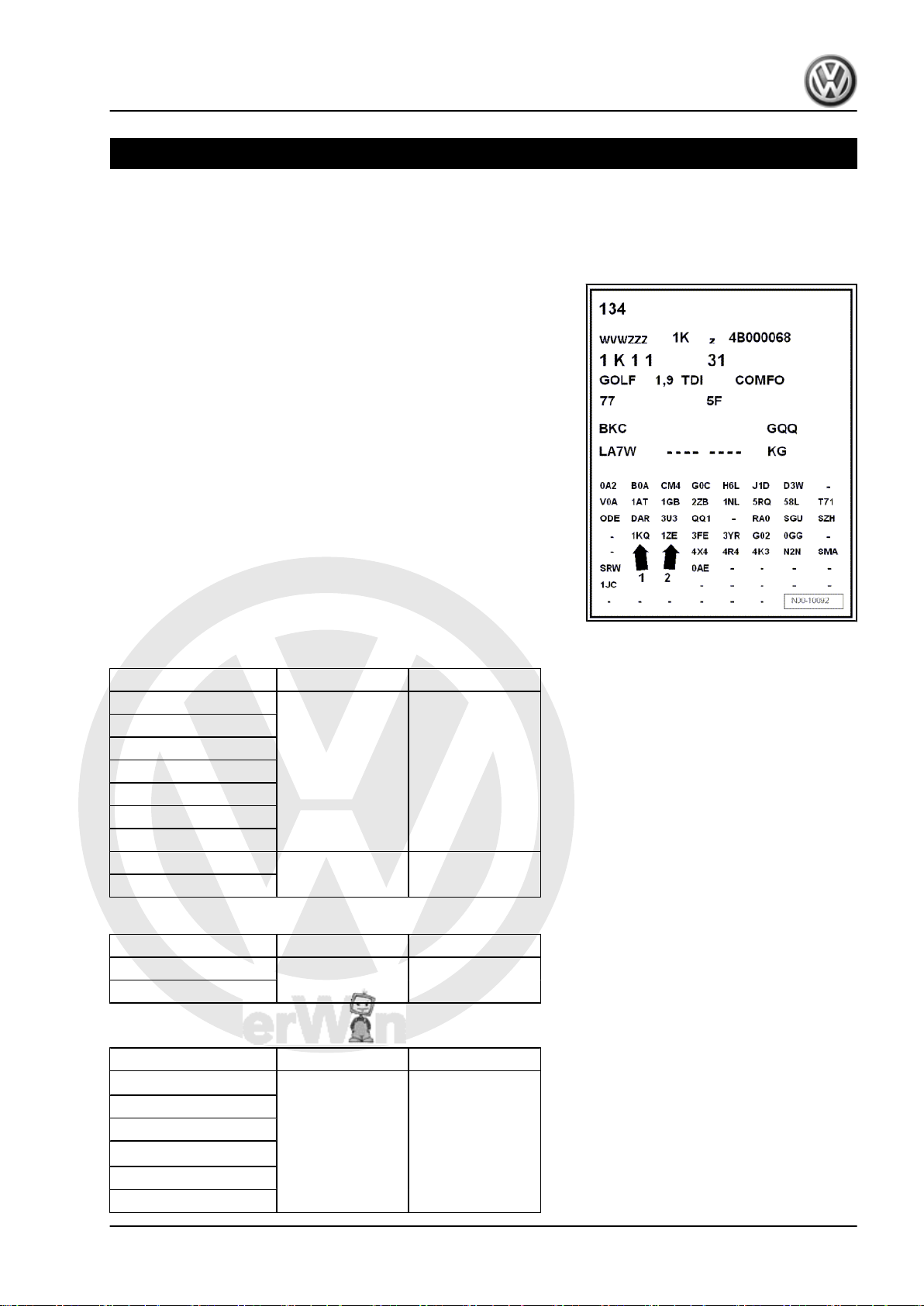
The type of brake system installed in the vehicle is indicated
among other things by the corresponding PR number on the ve‐
hicle data sticker.
Example of a vehicle data sticker:
In this example the vehicle is equipped with the following brakes:
♦ Arrow 1 - Rear brakes -1KQ
♦ Arrow 2 - Front brakes -1ZE
The vehicle data sticker can be found in the spare wheel well and
in the service booklet.
♦ Allocation ⇒ Electronic Parts Catalogue (ETKA) .
♦ The following tables explain the PR numbers. These are rel‐
evant for the brake caliper/brake disc and brake pads.
Brake systems - Edition 05.2008
1.1 Front brakes, Touran
Engine PR No. Front brake
1.6 l - 75 kW 1ZE FN3 (15”)
1.6 l - 85 kW FSI
1.4 l - 103 kW FSI
2.0 l -110 kW FSI
1.9 l - 66 kW TDI
1.9 l - 74, 77 kW TDI
2.0 l - 100, 103 kW TDI
1.4 l -125 kW FSI 1LJ FN3 (16”)
2.0 l - 125 kW TDI
Country-specific brake for Japan:
Engine PR No. Front brake
1.6 l - 85 kW FSI 1ZP FN3 (15”)
2.0 l -110 kW
1.2 Front brakes, Golf
Engine PR No. Front brake
1.4 l - 55, 59 kW
1ZF1) / 1ZM
1.4 l -66 kW FSI
1.6 l - 75 kW
1.6 l - 85 kW FSI
2)
2.0 l - 85 kW
1.9 l - 66 kW TDI
FS III (15”)
1. Brake allocation via PR No. 1
P
r
o
t
e
c
t
e
d
b
y
c
o
p
y
r
i
g
h
t
.
C
o
p
y
i
n
g
f
o
r
p
r
i
v
a
t
e
o
r
c
o
m
m
e
r
c
i
a
l
p
u
r
p
o
s
e
s
,
i
n
p
a
r
t
o
r
i
n
w
h
o
l
e
,
i
s
n
o
t
p
e
r
m
i
t
t
e
d
u
n
l
e
s
s
a
u
t
h
o
r
i
s
e
d
b
y
V
o
l
k
s
w
a
g
e
n
A
G
.
V
o
l
k
s
w
a
g
e
n
A
G
d
o
e
s
n
o
t
g
u
a
r
a
n
t
e
e
o
r
a
c
c
e
p
t
a
n
y
l
i
a
b
i
l
i
t
y
w
i
t
h
r
e
s
p
e
c
t
t
o
t
h
e
c
o
r
r
e
c
t
n
e
s
s
o
f
i
n
f
o
r
m
a
t
i
o
n
i
n
t
h
i
s
d
o
c
u
m
e
n
t
.
C
o
p
y
r
i
g
h
t
b
y
V
o
l
k
s
w
a
g
e
n
A
G
.
Eos 2006 ➤ , Golf 2004 ➤ , Golf Plus 2005 ➤ , Touran 2003 ➤
Brake systems - Edition 05.2008
1.9 l - 77 kW TDI
3)
2.0 l -55 kW SDI
1.6 l - 85 kW FSI
4)
1.4 l - 88, 90 kW FSI
1.4 l - 103, 110 kW FSI
2.0 l -110 kW FSI
1.9 l - 77 kW TDI
5)
2.0 l - 100, 103 kW TDI
1ZE FN3 (15”)
2.0 l -147 kW FSI 1LJ / 1LL FN3 (16”)
1.4 l -125 kW FSI 1LJ
2.0 l - 125 kW TDI
3.2 l -184 kW 1LM FNR-G (17”)
1)
the 1ZE brake was installed at the start of series production.
2)
Golf
3)
with 5-speed manual gearbox 0A4.
4)
Golf Plus
5)
with Direct Shift Gearbox 02E - 6-speed or four-wheel drive.
Country specific brake for North America / Japan:
Engine PR No. Front brake
1.6 l -75 kW 1ZP FN3 (15”)
1.6 l - 85 kW FSI
2.0 l -110 kW
2.5 l -110 kW
1.9 l - 74 kW TDI
2.0 l -147 kW FSI 1ZD / 1LV FN3 (16”)
1.3 Front brakes, Eos
Engine PR No. Front brake
1.6 l - 85 kW FSI 1ZE FN3 (15”)
2.0 l -110 kW FSI
2.0 l -147 kW FSI 1LJ FN3 (16”)
2.0 l - 100, 103 kW TDI
3.2 l -184 kW
Country specific brake for North America / Japan:
Engine PR No. Front brake
2.0 l -147 kW FSI 1ZD FN3 (16”)
3.2 l -184 kW
1.4 Rear brakes, Touran
Engine PR No. Rear brake
1.6 l - 75 kW 1KF CII 41 (15”)
1.6 l - 85 kW FSI
1.4 l -103 kW FSI
2.0 l -110 kW FSI
1.9 l - 66 kW TDI
2 Rep. Gr.00 - Technical data
P
r
o
t
e
c
t
e
d
b
y
c
o
p
y
r
i
g
h
t
.
C
o
p
y
i
n
g
f
o
r
p
r
i
v
a
t
e
o
r
c
o
m
m
e
r
c
i
a
l
p
u
r
p
o
s
e
s
,
i
n
p
a
r
t
o
r
i
n
w
h
o
l
e
,
i
s
n
o
t
p
e
r
m
i
t
t
e
d
u
n
l
e
s
s
a
u
t
h
o
r
i
s
e
d
b
y
V
o
l
k
s
w
a
g
e
n
A
G
.
V
o
l
k
s
w
a
g
e
n
A
G
d
o
e
s
n
o
t
g
u
a
r
a
n
t
e
e
o
r
a
c
c
e
p
t
a
n
y
l
i
a
b
i
l
i
t
y
w
i
t
h
r
e
s
p
e
c
t
t
o
t
h
e
c
o
r
r
e
c
t
n
e
s
s
o
f
i
n
f
o
r
m
a
t
i
o
n
i
n
t
h
i
s
d
o
c
u
m
e
n
t
.
C
o
p
y
r
i
g
h
t
b
y
V
o
l
k
s
w
a
g
e
n
A
G
.
Eos 2006 ➤ , Golf 2004 ➤ , Golf Plus 2005 ➤ , Touran 2003 ➤
Brake systems - Edition 05.2008
1.9 l - 74, 77 kW TDI
2.0 l - 100, 103 kW TDI
1.4 l -125 kW FSI
2.0 l - 125 kW TDI
1)
Gradual switch to 1KF from the end of 2006
1)
1KJ
CII 41 (16”)
Country-specific brake for Japan:
Engine PR No. Rear brake
1.6 l - 85 kW FSI 1KE CII 41 (15”)
2.0 l -110 kW
1.5 Rear brakes, front-wheel drive Golf
Without Golf Variant:
Engine PR No. Rear brake
1.4 l - 55, 59 kW 1KQ / 1KD CI 38 (15”)
1.4 l - 66 kW FSI
1.6 l - 75 kW
1.6 l - 85 kW FSI
2.0 l - 85 kW
1.4 l - 88, 90 kW FSI
1.4 l - 103, 110 kW FSI
2.0 l -110 kW FSI
2.0 l - 55 kW SDI
1.9 l - 66 kW TDI
1.9 l - 77 kW TDI
2.0 l - 100, 103 kW TDI
2.0 l - 147 kW FSI 1KY CII 38 (16”)
1.4 l - 125 kW FSI
2.0 l - 125 kW TDI
1)
Gradual switch to 1KD from the end of 2006
Golf Variant only:
Engine PR No. Rear brake
1.6 l - 75 kW 1KF CII 41 (15”)
1.6 l - 85 kW FSI
2.0 l - 110 kW FSI
1.9 l - 74, 77 kW TDI
2.0 l - 100, 103 kW TDI
1)
1KZ
Country specific brake for North America / Japan:
Engine PR No. Rear brake
1.6 l - 75 kW 1KE CII 41 (15”)
1.6 l - 85 kW FSI
2.0 l -110 kW
2.5 l - 110 kW
2.0 l - 147 kW FSI
1.9 l - 77 kW TDI
2.0 l - 100, 103 kW TDI
1. Brake allocation via PR No. 3
P
r
o
t
e
c
t
e
d
b
y
c
o
p
y
r
i
g
h
t
.
C
o
p
y
i
n
g
f
o
r
p
r
i
v
a
t
e
o
r
c
o
m
m
e
r
c
i
a
l
p
u
r
p
o
s
e
s
,
i
n
p
a
r
t
o
r
i
n
w
h
o
l
e
,
i
s
n
o
t
p
e
r
m
i
t
t
e
d
u
n
l
e
s
s
a
u
t
h
o
r
i
s
e
d
b
y
V
o
l
k
s
w
a
g
e
n
A
G
.
V
o
l
k
s
w
a
g
e
n
A
G
d
o
e
s
n
o
t
g
u
a
r
a
n
t
e
e
o
r
a
c
c
e
p
t
a
n
y
l
i
a
b
i
l
i
t
y
w
i
t
h
r
e
s
p
e
c
t
t
o
t
h
e
c
o
r
r
e
c
t
n
e
s
s
o
f
i
n
f
o
r
m
a
t
i
o
n
i
n
t
h
i
s
d
o
c
u
m
e
n
t
.
C
o
p
y
r
i
g
h
t
b
y
V
o
l
k
s
w
a
g
e
n
A
G
.
Eos 2006 ➤ , Golf 2004 ➤ , Golf Plus 2005 ➤ , Touran 2003 ➤
Brake systems - Edition 05.2008
2.0 l - 147 kW FSI 1KV CII 38 (16”)
1.6 Rear brakes, four-wheel drive Golf
Engine PR No. Rear brake
2.0 l - 110 kW FSI 1KF CII 41 (15”)
1.9 l - 77 kW TDI
2.0 l - 100, 103 kW TDI
3.2 l - 184 kW 2EL CII 41 (17”)
Country-specific brake for Japan:
Engine PR No. Rear brake
2.0 l - 110 kW 1KE CII 41 (15”)
1.7 Rear brakes, Eos
Engine PR No. Rear brake
1.6 l - 85 kW FSI 1KD CI 38 (15”)
2.0 l - 110 kW FSI
2.0 l - 100, 103 kW TDI
2.0 l - 147 kW FSI 1KZ CII 38 (16”)
3.2 l - 184 kW
Country specific brake for North America / Japan:
Engine PR No. Rear brake
2.0 l - 147 kW FSI 1KJ CII 41 (16”)
3.2 l - 184 kW
4 Rep. Gr.00 - Technical data
P
r
o
t
e
c
t
e
d
b
y
c
o
p
y
r
i
g
h
t
.
C
o
p
y
i
n
g
f
o
r
p
r
i
v
a
t
e
o
r
c
o
m
m
e
r
c
i
a
l
p
u
r
p
o
s
e
s
,
i
n
p
a
r
t
o
r
i
n
w
h
o
l
e
,
i
s
n
o
t
p
e
r
m
i
t
t
e
d
u
n
l
e
s
s
a
u
t
h
o
r
i
s
e
d
b
y
V
o
l
k
s
w
a
g
e
n
A
G
.
V
o
l
k
s
w
a
g
e
n
A
G
d
o
e
s
n
o
t
g
u
a
r
a
n
t
e
e
o
r
a
c
c
e
p
t
a
n
y
l
i
a
b
i
l
i
t
y
w
i
t
h
r
e
s
p
e
c
t
t
o
t
h
e
c
o
r
r
e
c
t
n
e
s
s
o
f
i
n
f
o
r
m
a
t
i
o
n
i
n
t
h
i
s
d
o
c
u
m
e
n
t
.
C
o
p
y
r
i
g
h
t
b
y
V
o
l
k
s
w
a
g
e
n
A
G
.
Eos 2006 ➤ , Golf 2004 ➤ , Golf Plus 2005 ➤ , Touran 2003 ➤
2 Technical data for brakes
2.1 Brake master cylinder and brake servo, Touran
Brake master cylinder ∅ in mm 22
Brake servo (LHD) ∅ in inches 11
Brake servo (RHD) ∅ in inches 7 / 8
2.2 Brake master cylinder and brake servo, Golf, Eos
Brake master cylinder ∅ in mm 22
Brake servo (LHD) ∅ in inches 10
Brake servo (RHD) ∅ in inches 7 / 8
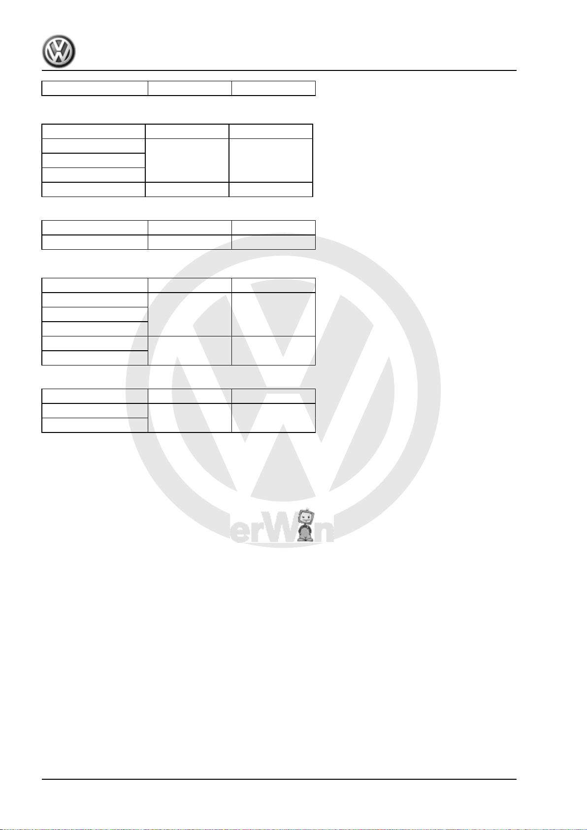
2.3 Front brakes
2.3.1 Front brakes FS III
Brake systems - Edition 05.2008
Item PR No.
1ZF / 1ZM
1 Brake caliper FS III (15”)
2 Brake pad,
mm 14
thickness
Brake pad, wear
mm 2
limit without
back plate
3 Brake disc ∅ in
Brake disc,
thickness
Brake disc,
wear limit
4 Brake caliper
piston
mm
mm 22
mm 19
∅ in
mm
280
54
2. Technical data for brakes 5
P
r
o
t
e
c
t
e
d
b
y
c
o
p
y
r
i
g
h
t
.
C
o
p
y
i
n
g
f
o
r
p
r
i
v
a
t
e
o
r
c
o
m
m
e
r
c
i
a
l
p
u
r
p
o
s
e
s
,
i
n
p
a
r
t
o
r
i
n
w
h
o
l
e
,
i
s
n
o
t
p
e
r
m
i
t
t
e
d
u
n
l
e
s
s
a
u
t
h
o
r
i
s
e
d
b
y
V
o
l
k
s
w
a
g
e
n
A
G
.
V
o
l
k
s
w
a
g
e
n
A
G
d
o
e
s
n
o
t
g
u
a
r
a
n
t
e
e
o
r
a
c
c
e
p
t
a
n
y
l
i
a
b
i
l
i
t
y
w
i
t
h
r
e
s
p
e
c
t
t
o
t
h
e
c
o
r
r
e
c
t
n
e
s
s
o
f
i
n
f
o
r
m
a
t
i
o
n
i
n
t
h
i
s
d
o
c
u
m
e
n
t
.
C
o
p
y
r
i
g
h
t
b
y
V
o
l
k
s
w
a
g
e
n
A
G
.
Eos 2006 ➤ , Golf 2004 ➤ , Golf Plus 2005 ➤ , Touran 2003 ➤
Brake systems - Edition 05.2008
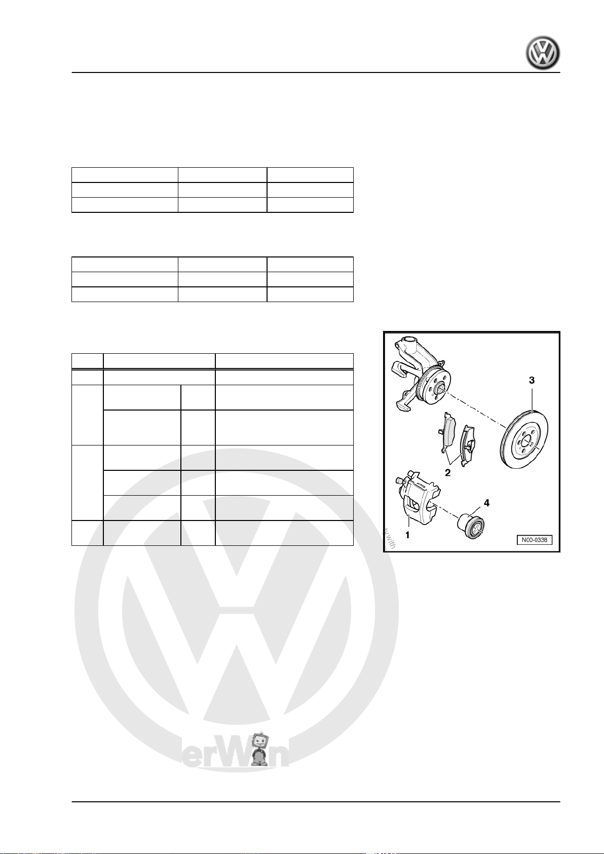
2.3.2 Front brakes FN 3
Item PR No.
1 Brake caliper FN3 (15”)
2 Brake pad,
thickness
Brake pad, wear
limit without
back plate
3 Brake disc ∅ in
Brake disc,
thickness
Brake disc,
wear limit
4 Brake caliper
piston
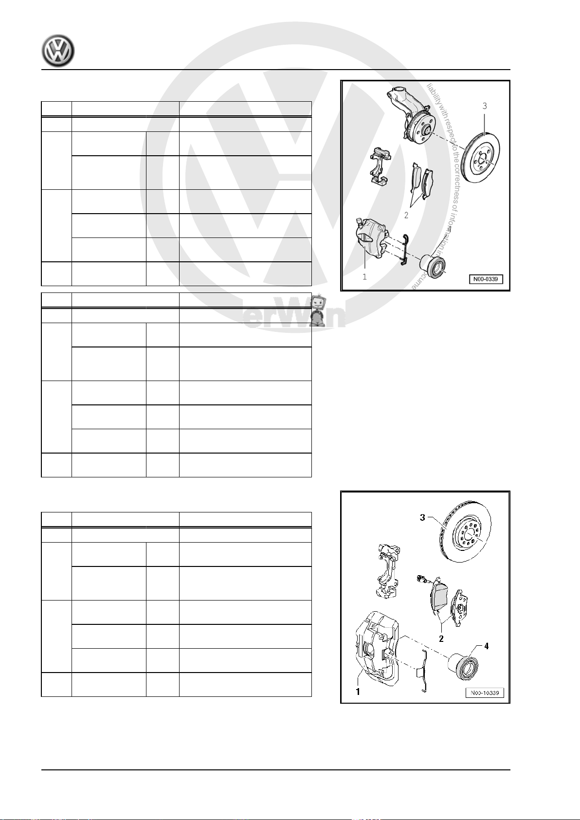
Item PR No.
1 Brake caliper FN3 (16”)
2 Brake pad,
thickness
Brake pad, wear
mm 14
mm 2
mm
mm 25
mm 22
∅ in
mm
mm 14
mm 2
1LJ / 1LL / 1ZD / 1LV
limit without
1ZE / 1ZP
back plate
3 Brake disc ∅ in
mm
Brake disc,
mm 25
thickness
Brake disc,
mm 22
wear limit
4 Brake caliper
piston
∅ in
mm
288
54
312
54
2.3.3 Front brakes FNR-G
Item PR No.
1 Brake caliper FNR-G (17”)
2 Brake pad,
thickness
Brake pad, wear
limit without
back plate
3 Brake disc ∅ in
Brake disc,
thickness
Brake disc,
wear limit
4 Brake caliper
piston
1LK / 1LM
mm 14
mm 2
mm
mm 30
mm 27
∅ in
mm
345
57
6 Rep. Gr.00 - Technical data
P
r
o
t
e
c
t
e
d
b
y
c
o
p
y
r
i
g
h
t
.
C
o
p
y
i
n
g
f
o
r
p
r
i
v
a
t
e
o
r
c
o
m
m
e
r
c
i
a
l
p
u
r
p
o
s
e
s
,
i
n
p
a
r
t
o
r
i
n
w
h
o
l
e
,
i
s
n
o
t
p
e
r
m
i
t
t
e
d
u
n
l
e
s
s
a
u
t
h
o
r
i
s
e
d
b
y
V
o
l
k
s
w
a
g
e
n
A
G
.
V
o
l
k
s
w
a
g
e
n
A
G
d
o
e
s
n
o
t
g
u
a
r
a
n
t
e
e
o
r
a
c
c
e
p
t
a
n
y
l
i
a
b
i
l
i
t
y
w
i
t
h
r
e
s
p
e
c
t
t
o
t
h
e
c
o
r
r
e
c
t
n
e
s
s
o
f
i
n
f
o
r
m
a
t
i
o
n
i
n
t
h
i
s
d
o
c
u
m
e
n
t
.
C
o
p
y
r
i
g
h
t
b
y
V
o
l
k
s
w
a
g
e
n
A
G
.
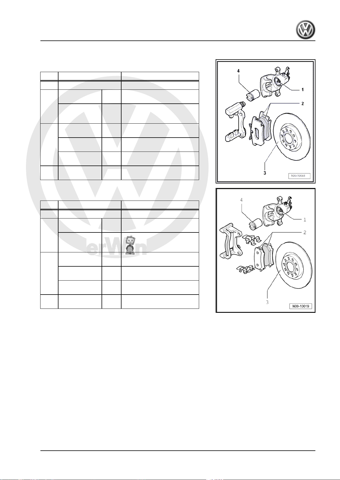
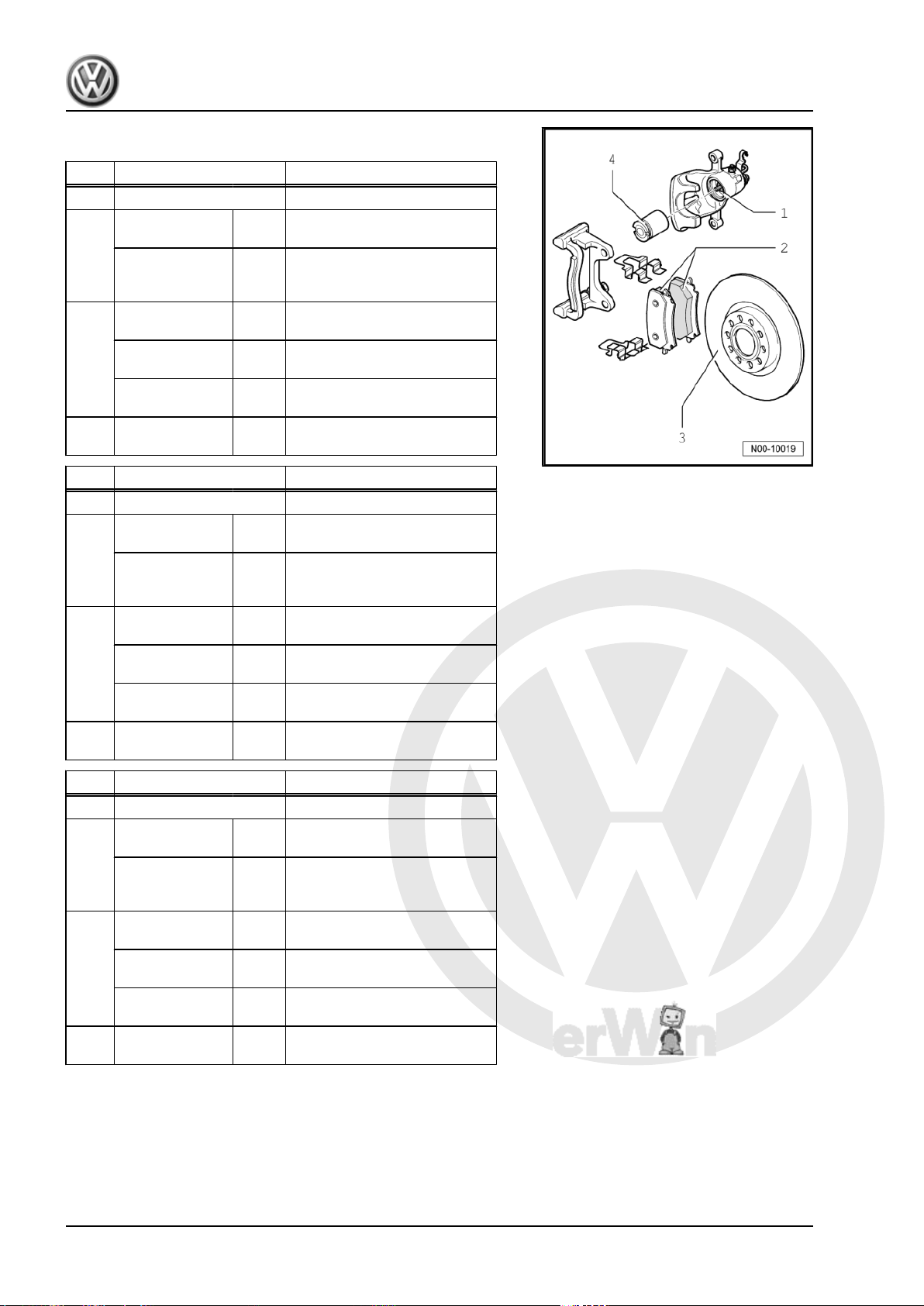
2.4 Rear brakes (disc brakes)
2.4.1 Rear brakes CI 38
Item PR No.
1 Brake caliper CI 38 (15”)
2 Brake pad,
3 Brake disc ∅ in
4 Brake caliper
2.4.2 Rear brakes CII 38
Item PR No.
1 Brake caliper CII 38 (16")
2 Brake pad,
thickness
Brake pad, wear
limit without
back plate
Brake disc,
thickness
Brake disc,
wear limit
piston
thickness
Brake pad, wear
limit without
back plate
3 Brake disc ∅ in
Brake disc,
thickness
Brake disc,
wear limit
4 Brake caliper
piston
mm 11
mm 2
mm
mm 10
mm 8
∅ in
mm
mm 11
mm
mm 12
∅ in
mm
Eos 2006 ➤ , Golf 2004 ➤ , Golf Plus 2005 ➤ , Touran 2003 ➤
Brake systems - Edition 05.2008
1KQ / 1KD
255
38
1KY / 1KZ / 1KV
286
2
10
38
2. Technical data for brakes 7
P
r
o
t
e
c
t
e
d
b
y
c
o
p
y
r
i
g
h
t
.
C
o
p
y
i
n
g
f
o
r
p
r
i
v
a
t
e
o
r
c
o
m
m
e
r
c
i
a
l
p
u
r
p
o
s
e
s
,
i
n
p
a
r
t
o
r
i
n
w
h
o
l
e
,
i
s
n
o
t
p
e
r
m
i
t
t
e
d
u
n
l
e
s
s
a
u
t
h
o
r
i
s
e
d
b
y
V
o
l
k
s
w
a
g
e
n
A
G
.
V
o
l
k
s
w
a
g
e
n
A
G
d
o
e
s
n
o
t
g
u
a
r
a
n
t
e
e
o
r
a
c
c
e
p
t
a
n
y
l
i
a
b
i
l
i
t
y
w
i
t
h
r
e
s
p
e
c
t
t
o
t
h
e
c
o
r
r
e
c
t
n
e
s
s
o
f
i
n
f
o
r
m
a
t
i
o
n
i
n
t
h
i
s
d
o
c
u
m
e
n
t
.
C
o
p
y
r
i
g
h
t
b
y
V
o
l
k
s
w
a
g
e
n
A
G
.
Eos 2006 ➤ , Golf 2004 ➤ , Golf Plus 2005 ➤ , Touran 2003 ➤
Brake systems - Edition 05.2008
2.4.3 Rear brakes CII 41
Item PR No.
1KF / 1KE
1 Brake caliper CII 41 (15")
2 Brake pad,
mm 11
thickness
Brake pad, wear
mm 2
limit without
back plate
3 Brake disc ∅ in
260
mm
Brake disc,
mm 12
thickness
Brake disc,
mm 10
wear limit
4 Brake caliper
piston
Item PR No.
∅ in
mm
41
1KJ
1 Brake caliper CII 41 (16")
2 Brake pad,
mm 11
thickness
Brake pad, wear
limit without
back plate
3 Brake disc ∅ in
Brake disc,
thickness
Brake disc,
wear limit
4 Brake caliper
piston
Item PR No.
1 Brake caliper CII 41 (17")
2 Brake pad,
thickness
Brake pad, wear
limit without
back plate
3 Brake disc ∅ in
Brake disc,
thickness
Brake disc,
wear limit
4 Brake caliper
piston
mm 2
mm
mm 12
mm 10
∅ in
mm
mm 11
mm 2
mm
mm 22
mm 20
∅ in
mm
2EL / 2EA
286
41
310
41
8 Rep. Gr.00 - Technical data
P
r
o
t
e
c
t
e
d
b
y
c
o
p
y
r
i
g
h
t
.
C
o
p
y
i
n
g
f
o
r
p
r
i
v
a
t
e
o
r
c
o
m
m
e
r
c
i
a
l
p
u
r
p
o
s
e
s
,
i
n
p
a
r
t
o
r
i
n
w
h
o
l
e
,
i
s
n
o
t
p
e
r
m
i
t
t
e
d
u
n
l
e
s
s
a
u
t
h
o
r
i
s
e
d
b
y
V
o
l
k
s
w
a
g
e
n
A
G
.
V
o
l
k
s
w
a
g
e
n
A
G
d
o
e
s
n
o
t
g
u
a
r
a
n
t
e
e
o
r
a
c
c
e
p
t
a
n
y
l
i
a
b
i
l
i
t
y
w
i
t
h
r
e
s
p
e
c
t
t
o
t
h
e
c
o
r
r
e
c
t
n
e
s
s
o
f
i
n
f
o
r
m
a
t
i
o
n
i
n
t
h
i
s
d
o
c
u
m
e
n
t
.
C
o
p
y
r
i
g
h
t
b
y
V
o
l
k
s
w
a
g
e
n
A
G
.
Eos 2006 ➤ , Golf 2004 ➤ , Golf Plus 2005 ➤ , Touran 2003 ➤
3 Brake test
3.1 General
♦ The drive is provided by the roller dynamometer.
♦ For the test, ensure for vehicles with a manual gearbox that
the gear lever is in neutral and for vehicles with an automatic
gearbox, that the selector lever is in “N”.
♦ For test, observe specifications provided by manufacturer of
roller dynamometer.
Note
The brake regulation systems do not function when ignition is off.
3.2 Test for vehicles with front-wheel drive
The brake test must be performed on a single-axle roller dyna‐
mometer.
The maximum test speed must not exceed 6 km/h.
The test rigs authorised by Volkswagen fulfil these requirements.
3.3 Test for vehicles with four-wheel drive
3.3.1 The brake test should be performed on
Contra-rotating means that the dynamometer rollers are driven
via a Haldex coupling
a single-axle roller dynamometer with
contra-rotating rollers for four-wheel
drive vehicles.
forwards on one side and backwards on the opposite side.
This prevents brake forces being transferred to the drive train.
The forward rotating wheel is measured during the test, which
means two brake tests per axle must be performed.
The maximum test speed must not exceed 6 km/h.
The test rigs authorised by Volkswagen fulfil these requirements.
3.3.2 If no test rig is available for four-wheel drive vehicles, the brake test can also be carried out on a standard single-axle roller dynamometer as follows:
Brake systems - Edition 05.2008
– Drive vehicle forwards onto the rollers.
– Switch engine off and wait for 2 seconds.
– Carry out front brake test.
– Start engine and wait for approx. 5 seconds until sufficient
vacuum has been built up.
– Drive vehicle forwards until rear wheels are positioned on roll‐
ers.
3. Brake test 9

P
r
o
t
e
c
t
e
d
b
y
c
o
p
y
r
i
g
h
t
.
C
o
p
y
i
n
g
f
o
r
p
r
i
v
a
t
e
o
r
c
o
m
m
e
r
c
i
a
l
p
u
r
p
o
s
e
s
,
i
n
p
a
r
t
o
r
i
n
w
h
o
l
e
,
i
s
n
o
t
p
e
r
m
i
t
t
e
d
u
n
l
e
s
s
a
u
t
h
o
r
i
s
e
d
b
y
V
o
l
k
s
w
a
g
e
n
A
G
.
V
o
l
k
s
w
a
g
e
n
A
G
d
o
e
s
n
o
t
g
u
a
r
a
n
t
e
e
o
r
a
c
c
e
p
t
a
n
y
l
i
a
b
i
l
i
t
y
w
i
t
h
r
e
s
p
e
c
t
t
o
t
h
e
c
o
r
r
e
c
t
n
e
s
s
o
f
i
n
f
o
r
m
a
t
i
o
n
i
n
t
h
i
s
d
o
c
u
m
e
n
t
.
C
o
p
y
r
i
g
h
t
b
y
V
o
l
k
s
w
a
g
e
n
A
G
.
Eos 2006 ➤ , Golf 2004 ➤ , Golf Plus 2005 ➤ , Touran 2003 ➤
Brake systems - Edition 05.2008
– Switch engine off and wait for 2 seconds.
– Carry out rear brake test.
– Start engine and wait for approx. 5 seconds until sufficient
vacuum has been built up.
10 Rep. Gr.00 - Technical data
P
r
o
t
e
c
t
e
d
b
y
c
o
p
y
r
i
g
h
t
.
C
o
p
y
i
n
g
f
o
r
p
r
i
v
a
t
e
o
r
c
o
m
m
e
r
c
i
a
l
p
u
r
p
o
s
e
s
,
i
n
p
a
r
t
o
r
i
n
w
h
o
l
e
,
i
s
n
o
t
p
e
r
m
i
t
t
e
d
u
n
l
e
s
s
a
u
t
h
o
r
i
s
e
d
b
y
V
o
l
k
s
w
a
g
e
n
A
G
.
V
o
l
k
s
w
a
g
e
n
A
G
d
o
e
s
n
o
t
g
u
a
r
a
n
t
e
e
o
r
a
c
c
e
p
t
a
n
y
l
i
a
b
i
l
i
t
y
w
i
t
h
r
e
s
p
e
c
t
t
o
t
h
e
c
o
r
r
e
c
t
n
e
s
s
o
f
i
n
f
o
r
m
a
t
i
o
n
i
n
t
h
i
s
d
o
c
u
m
e
n
t
.
C
o
p
y
r
i
g
h
t
b
y
V
o
l
k
s
w
a
g
e
n
A
G
.
Eos 2006 ➤ , Golf 2004 ➤ , Golf Plus 2005 ➤ , Touran 2003 ➤
45 – Anti-lock brake system
1 General notes on anti-lock brake sys‐
tem
The ABS brake system is divided diagonally. The servo-assis‐
tance is effected pneumatically by the vacuum brake servo unit.
Vehicles with ABS are not fitted with a mechanical brake pressure
regulator. Specially matched software in the control unit regulates
the brake force distribution on the rear axle.
Faults in the ABS do not influence the brake system and servo
assistance. The conventional brake system remains functional
even without ABS. A change in braking behaviour is to be reck‐
oned with. After the ABS warning lamp comes on, the rear wheels
may lock prematurely during braking!
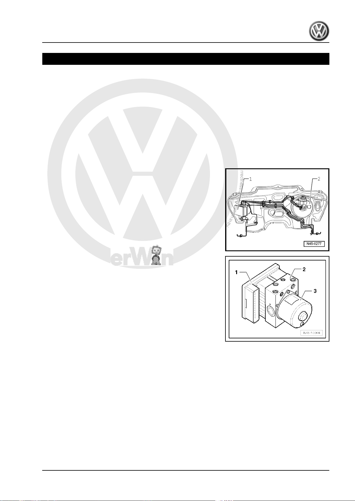
ABS layout in left-hand drive vehicle.
1 - Hydraulic unit and control unit
2 - Brake servo
The hydraulic unit -2- and control unit -1- form one component.
They can be separated only when removed. Hydraulic pump -3must not be separated from hydraulic unit.
With ABS/EDL/TCS/ESP - separation is not possible in vehicles
with hydraulic brake servo or hill hold assist.
Brake systems - Edition 05.2008
1. General notes on anti-lock brake system 11

P
r
o
t
e
c
t
e
d
b
y
c
o
p
y
r
i
g
h
t
.
C
o
p
y
i
n
g
f
o
r
p
r
i
v
a
t
e
o
r
c
o
m
m
e
r
c
i
a
l
p
u
r
p
o
s
e
s
,
i
n
p
a
r
t
o
r
i
n
w
h
o
l
e
,
i
s
n
o
t
p
e
r
m
i
t
t
e
d
u
n
l
e
s
s
a
u
t
h
o
r
i
s
e
d
b
y
V
o
l
k
s
w
a
g
e
n
A
G
.
V
o
l
k
s
w
a
g
e
n
A
G
d
o
e
s
n
o
t
g
u
a
r
a
n
t
e
e
o
r
a
c
c
e
p
t
a
n
y
l
i
a
b
i
l
i
t
y
w
i
t
h
r
e
s
p
e
c
t
t
o
t
h
e
c
o
r
r
e
c
t
n
e
s
s
o
f
i
n
f
o
r
m
a
t
i
o
n
i
n
t
h
i
s
d
o
c
u
m
e
n
t
.
C
o
p
y
r
i
g
h
t
b
y
V
o
l
k
s
w
a
g
e
n
A
G
.
Eos 2006 ➤ , Golf 2004 ➤ , Golf Plus 2005 ➤ , Touran 2003 ➤
Brake systems - Edition 05.2008
2 Notes for repair work on anti-lock
brake system
♦ Before carrying out repair work on the anti-lock brake system,
determine the cause of the fault as well as the control unit code
using “Guided Fault Finding”.
“Guided Fault Finding” is carried out with the vehicle diagnostic,
testing and information system -VAS 5051- .
♦ Disconnect battery earth strap with ignition switched off.
♦ Before carrying out welding work with an electric welding unit,
note ⇒ General Information; Body Repairs, General Body Re‐
pairs .
♦ When working with brake fluid, observe the valid, relevant
safety precautions and notes ⇒ page 130 .
♦ After work for which the brake system had to be opened, bleed
the brake system with brake filling and bleeding equipment VAS 5234- or -V.A.G 1869- ⇒ page 130 .
♦ During the final road test, ensure that a controlled brake test
is performed at least once (pulsations must be felt at the brake
pedal).
♦ Absolute cleanliness is required when working on the anti-lock
brake system. It is not permitted to use any products which
contain mineral oil, such as oils, greases etc.
♦ Thoroughly clean all unions and the adjacent areas before
loosening. Do not use aggressive cleaning agents such as
brake cleanser, petrol, thinners or similar.
♦ Place removed parts on a clean surface and cover.
♦ After separating the control unit/hydraulic unit, use the trans‐
port protection for the contact pins.
♦ If repairs cannot be carried out immediately, carefully cover or
seal open components. (Use sealing plugs from repair kit
1 H0 698 311 A).
♦ Only use lint-free cloths.
♦ Only unpack replacement parts immediately prior to fitting.
♦ Only use genuine packed parts.
♦ When the system is open, do not work with compressed air
and do not move the vehicle.
♦ Make sure not to touch any contact surfaces on the connector,
pressure sensor and control unit as well as the silicone gel by
hand or with objects.
♦ During painting operations, the electronic control unit can be
exposed to a maximum temperature of 95 °C for only a short
period, and to a maximum of 85 °C for longer periods (approx.
2 hours). Ensure that no brake fluid enters connectors.
12 Rep. Gr.45 - Anti-lock brake system
P
r
o
t
e
c
t
e
d
b
y
c
o
p
y
r
i
g
h
t
.
C
o
p
y
i
n
g
f
o
r
p
r
i
v
a
t
e
o
r
c
o
m
m
e
r
c
i
a
l
p
u
r
p
o
s
e
s
,
i
n
p
a
r
t
o
r
i
n
w
h
o
l
e
,
i
s
n
o
t
p
e
r
m
i
t
t
e
d
u
n
l
e
s
s
a
u
t
h
o
r
i
s
e
d
b
y
V
o
l
k
s
w
a
g
e
n
A
G
.
V
o
l
k
s
w
a
g
e
n
A
G
d
o
e
s
n
o
t
g
u
a
r
a
n
t
e
e
o
r
a
c
c
e
p
t
a
n
y
l
i
a
b
i
l
i
t
y
w
i
t
h
r
e
s
p
e
c
t
t
o
t
h
e
c
o
r
r
e
c
t
n
e
s
s
o
f
i
n
f
o
r
m
a
t
i
o
n
i
n
t
h
i
s
d
o
c
u
m
e
n
t
.
C
o
p
y
r
i
g
h
t
b
y
V
o
l
k
s
w
a
g
e
n
A
G
.
Eos 2006 ➤ , Golf 2004 ➤ , Golf Plus 2005 ➤ , Touran 2003 ➤
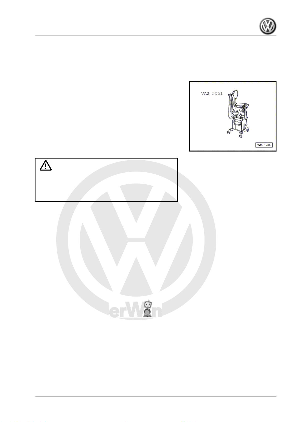
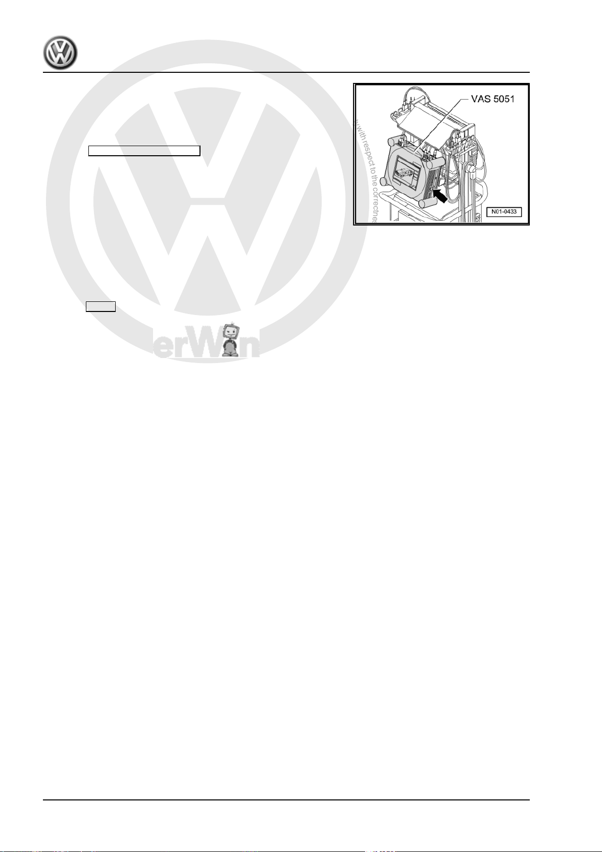
3 Connecting -VAS 5051- and select‐
ing functions
Special tools and workshop equipment required
♦ Vehicle diagnosis, testing and information system -VAS 5051-
♦ Diagnosis cable -VAS 5051/1- or -VAS 5051/3-
WARNING
♦ During a road test, you must always secure testing and
measuring equipment on the back seat.
♦ These devices may be operated only by a passenger while
the vehicle is in motion.
– Connect connector of diagnosis cable -VAS 5051/1- or -
VAS 5051/3- to diagnostic connection.
Brake systems - Edition 05.2008
3. Connecting VAS 5051 and selecting functions 13
P
r
o
t
e
c
t
e
d
b
y
c
o
p
y
r
i
g
h
t
.
C
o
p
y
i
n
g
f
o
r
p
r
i
v
a
t
e
o
r
c
o
m
m
e
r
c
i
a
l
p
u
r
p
o
s
e
s
,
i
n
p
a
r
t
o
r
i
n
w
h
o
l
e
,
i
s
n
o
t
p
e
r
m
i
t
t
e
d
u
n
l
e
s
s
a
u
t
h
o
r
i
s
e
d
b
y
V
o
l
k
s
w
a
g
e
n
A
G
.
V
o
l
k
s
w
a
g
e
n
A
G
d
o
e
s
n
o
t
g
u
a
r
a
n
t
e
e
o
r
a
c
c
e
p
t
a
n
y
l
i
a
b
i
l
i
t
y
w
i
t
h
r
e
s
p
e
c
t
t
o
t
h
e
c
o
r
r
e
c
t
n
e
s
s
o
f
i
n
f
o
r
m
a
t
i
o
n
i
n
t
h
i
s
d
o
c
u
m
e
n
t
.
C
o
p
y
r
i
g
h
t
b
y
V
o
l
k
s
w
a
g
e
n
A
G
.
Eos 2006 ➤ , Golf 2004 ➤ , Golf Plus 2005 ➤ , Touran 2003 ➤
Brake systems - Edition 05.2008
– Switch on tester -arrow-.
The tester is ready for operation when the selector buttons for the
operating modes appear on the screen.
– Switch on ignition.
– Touch Guided Fault Finding on screen.
– Select one after another:
♦ Brand
♦ Type
♦ Model year
♦ Body version
♦ Engine code
– Confirm data entered.
Wait until tester has interrogated all control units in vehicle.
– Press Go to and select function “Function/component selec‐
tion”.
– Select “Running gear” on display.
– Select “Brake systems” on display.
– Select “01 Self-diagnosis capable system …” shown on dis‐
play.
– Select “Anti-lock brake system …” shown on display.
– Select “Function” shown on display.
Now all possible functions from the anti-lock brake system instal‐
led in the vehicle will be displayed.
– Select desired function on display.
14 Rep. Gr.45 - Anti-lock brake system
P
r
o
t
e
c
t
e
d
b
y
c
o
p
y
r
i
g
h
t
.
C
o
p
y
i
n
g
f
o
r
p
r
i
v
a
t
e
o
r
c
o
m
m
e
r
c
i
a
l
p
u
r
p
o
s
e
s
,
i
n
p
a
r
t
o
r
i
n
w
h
o
l
e
,
i
s
n
o
t
p
e
r
m
i
t
t
e
d
u
n
l
e
s
s
a
u
t
h
o
r
i
s
e
d
b
y
V
o
l
k
s
w
a
g
e
n
A
G
.
V
o
l
k
s
w
a
g
e
n
A
G
d
o
e
s
n
o
t
g
u
a
r
a
n
t
e
e
o
r
a
c
c
e
p
t
a
n
y
l
i
a
b
i
l
i
t
y
w
i
t
h
r
e
s
p
e
c
t
t
o
t
h
e
c
o
r
r
e
c
t
n
e
s
s
o
f
i
n
f
o
r
m
a
t
i
o
n
i
n
t
h
i
s
d
o
c
u
m
e
n
t
.
C
o
p
y
r
i
g
h
t
b
y
V
o
l
k
s
w
a
g
e
n
A
G
.
Eos 2006 ➤ , Golf 2004 ➤ , Golf Plus 2005 ➤ , Touran 2003 ➤
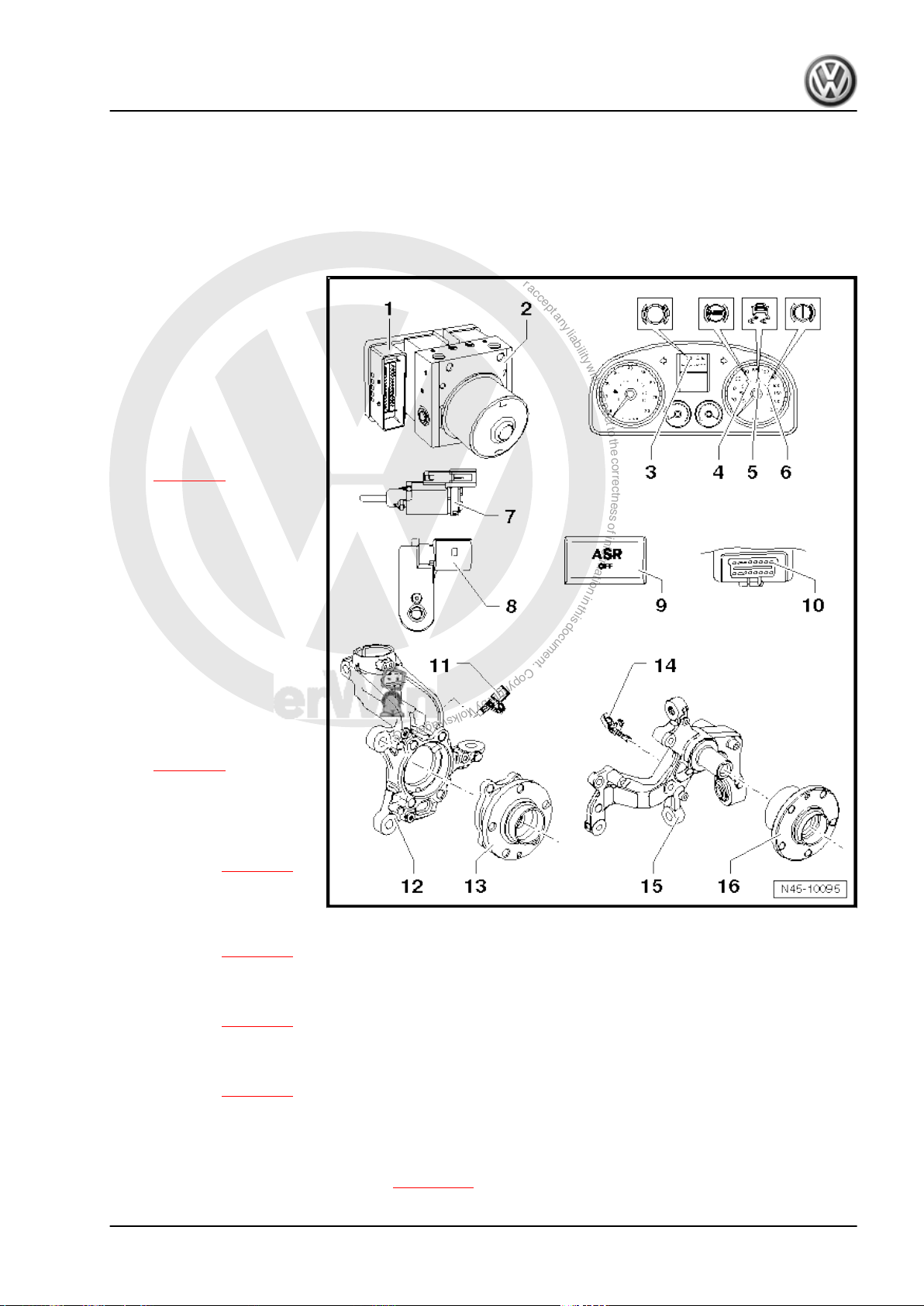
4 Electrical/electronic components and
fitting locations
4.1 ABS Mark 70 (ABS/TCS)
1 - ABS control unit -J104-
❑ Fitting location: on the
❑ Do not separate con‐
❑ Removing and installing
2 - ABS hydraulic unit -N55-
❑ Fitting location: on right
The hydraulic unit consists of
the components:
❑ ABS hydraulic pump -
❑ Valve block (includes in‐
❑ ABS hydraulic pump -
hydraulic unit on right in
engine compartment.
nector before success‐
fully completing self-di‐
agnosis. Switch ignition
off before disconnecting
connector.
⇒ page 28
in engine compartment.
V64-
let/outlet valves)
V64- and valve block
must not be separated
from one another.
❑ Removing and installing
⇒ page 28
3 - Brake pad warning lamp K32-
❑ Fitting location: in dash
panel insert.
❑ Function: ⇒ page 23 .
4 - ABS warning lamp -K47-
❑ Fitting location: in dash
panel insert.
❑ Function: ⇒ page 23 .
5 - Traction control system warning lamp -K86-
❑ Fitting location: in dash panel insert.
❑ Function: ⇒ page 23 .
Brake systems - Edition 05.2008
6 - Brake system warning lamp -K118-
❑ Fitting location: in dash panel insert.
❑ Function: ⇒ page 23 .
7 - Brake light switch -F- up to week 45/2005
❑ Including brake pedal switch -F47- .
❑ Fitting location: on brake pedal.
❑ Removing, installing and adjusting ⇒ page 110 .
4. Electrical/electronic components and fitting locations 15
P
r
o
t
e
c
t
e
d
b
y
c
o
p
y
r
i
g
h
t
.
C
o
p
y
i
n
g
f
o
r
p
r
i
v
a
t
e
o
r
c
o
m
m
e
r
c
i
a
l
p
u
r
p
o
s
e
s
,
i
n
p
a
r
t
o
r
i
n
w
h
o
l
e
,
i
s
n
o
t
p
e
r
m
i
t
t
e
d
u
n
l
e
s
s
a
u
t
h
o
r
i
s
e
d
b
y
V
o
l
k
s
w
a
g
e
n
A
G
.
V
o
l
k
s
w
a
g
e
n
A
G
d
o
e
s
n
o
t
g
u
a
r
a
n
t
e
e
o
r
a
c
c
e
p
t
a
n
y
l
i
a
b
i
l
i
t
y
w
i
t
h
r
e
s
p
e
c
t
t
o
t
h
e
c
o
r
r
e
c
t
n
e
s
s
o
f
i
n
f
o
r
m
a
t
i
o
n
i
n
t
h
i
s
d
o
c
u
m
e
n
t
.
C
o
p
y
r
i
g
h
t
b
y
V
o
l
k
s
w
a
g
e
n
A
G
.
Eos 2006 ➤ , Golf 2004 ➤ , Golf Plus 2005 ➤ , Touran 2003 ➤
Brake systems - Edition 05.2008
8 - Brake light switch -F- from week 45/2005
❑ Including brake pedal switch -F47- .
❑ Fitting location: on brake master cylinder.
❑ Removing and installing ⇒ page 138
9 - TCS button -E256-
❑ Fitting location: in centre console.
10 - Diagnostic connection
❑ Fitting location: driver side footwell cover.
11 - Front right speed sensor -G45- / front left speed sensor -G47-
❑ Removing and installing ⇒ page 56
12 - Wheel bearing housing
13 - Wheel bearing/hub unit
❑ ABS sensor ring is installed in the wheel bearing.
14 - Rear right speed sensor -G44- / rear left speed sensor -G46-
❑ Removing and installing (front-wheel drive) ⇒ page 57
❑ Removing and installing (four-wheel drive) ⇒ page 58
15 - Rear axle assembly with stub axle
16 - Wheel hub with wheel bearing
❑ ABS sensor ring is installed in the wheel bearing.
16 Rep. Gr.45 - Anti-lock brake system

P
r
o
t
e
c
t
e
d
b
y
c
o
p
y
r
i
g
h
t
.
C
o
p
y
i
n
g
f
o
r
p
r
i
v
a
t
e
o
r
c
o
m
m
e
r
c
i
a
l
p
u
r
p
o
s
e
s
,
i
n
p
a
r
t
o
r
i
n
w
h
o
l
e
,
i
s
n
o
t
p
e
r
m
i
t
t
e
d
u
n
l
e
s
s
a
u
t
h
o
r
i
s
e
d
b
y
V
o
l
k
s
w
a
g
e
n
A
G
.
V
o
l
k
s
w
a
g
e
n
A
G
d
o
e
s
n
o
t
g
u
a
r
a
n
t
e
e
o
r
a
c
c
e
p
t
a
n
y
l
i
a
b
i
l
i
t
y
w
i
t
h
r
e
s
p
e
c
t
t
o
t
h
e
c
o
r
r
e
c
t
n
e
s
s
o
f
i
n
f
o
r
m
a
t
i
o
n
i
n
t
h
i
s
d
o
c
u
m
e
n
t
.
C
o
p
y
r
i
g
h
t
b
y
V
o
l
k
s
w
a
g
e
n
A
G
.
Eos 2006 ➤ , Golf 2004 ➤ , Golf Plus 2005 ➤ , Touran 2003 ➤
4.2 ABS Mark 60 (ABS/EDL/TCS/ESP)
1 - ABS control unit -J104-
❑ Fitting location: on the
hydraulic unit on right in
engine compartment.
❑ Do not separate con‐
nector before success‐
fully completing self-di‐
agnosis. Switch ignition
off before disconnecting
connector.
❑ Removing and installing
⇒ page 36
2 - ABS hydraulic unit -N55-
❑ Fitting location: on right
in engine compartment.
The hydraulic unit consists of
the components:
❑ ABS hydraulic pump -
V64-
❑ Brake pressure sender -
G201-
❑ Valve block (includes in‐
let/outlet valves)
❑ ABS hydraulic pump -
V64- and valve block
must not be separated
from one another.
❑ Removing and installing
⇒ page 36
3 - Brake pad warning lamp K32-
❑ Fitting location: in dash
panel insert.
❑ Function: ⇒ page 23 .
4 - ABS warning lamp -K47-
❑ Fitting location: in dash panel insert.
❑ Function: ⇒ page 23 .
5 - ESP and TCS warning lamp -K155-
❑ Only vehicles with ABS/EDL/TCS/ESP.
❑ Fitting location: in dash panel insert.
❑ Function: ⇒ page 23 .
6 - Brake system warning lamp -K118-
❑ Fitting location: in dash panel insert.
❑ Function: ⇒ page 23 .
7 - Brake light switch -F- up to week 45/2005
❑ Including brake pedal switch -F47- .
❑ Fitting location: on brake pedal.
❑ Removing and installing ⇒ page 110
8 - Brake light switch -F- from week 45/2005
❑ Including brake pedal switch -F47- .
❑ Fitting location: on brake master cylinder.
Brake systems - Edition 05.2008
4. Electrical/electronic components and fitting locations 17
P
r
o
t
e
c
t
e
d
b
y
c
o
p
y
r
i
g
h
t
.
C
o
p
y
i
n
g
f
o
r
p
r
i
v
a
t
e
o
r
c
o
m
m
e
r
c
i
a
l
p
u
r
p
o
s
e
s
,
i
n
p
a
r
t
o
r
i
n
w
h
o
l
e
,
i
s
n
o
t
p
e
r
m
i
t
t
e
d
u
n
l
e
s
s
a
u
t
h
o
r
i
s
e
d
b
y
V
o
l
k
s
w
a
g
e
n
A
G
.
V
o
l
k
s
w
a
g
e
n
A
G
d
o
e
s
n
o
t
g
u
a
r
a
n
t
e
e
o
r
a
c
c
e
p
t
a
n
y
l
i
a
b
i
l
i
t
y
w
i
t
h
r
e
s
p
e
c
t
t
o
t
h
e
c
o
r
r
e
c
t
n
e
s
s
o
f
i
n
f
o
r
m
a
t
i
o
n
i
n
t
h
i
s
d
o
c
u
m
e
n
t
.
C
o
p
y
r
i
g
h
t
b
y
V
o
l
k
s
w
a
g
e
n
A
G
.
Eos 2006 ➤ , Golf 2004 ➤ , Golf Plus 2005 ➤ , Touran 2003 ➤
Brake systems - Edition 05.2008
❑ Removing and installing ⇒ page 138
9 - TCS and ESP button -E256-
❑ Only vehicles with ABS/EDL/TCS/ESP.
❑ Fitting location: in centre console.
10 - ESP sensor unit -G419-
❑ Only vehicles with ABS/EDL/TCS/ESP.
❑ Fitting location in Touran: behind glove box.
❑ Fitting location in Golf and Eos: under right front seat.
❑ Combined lateral acceleration sender -G200- , yaw rate sender -G202- and longitudinal acceleration
sender -G251❑ Combined in one housing.
❑ Removing and installing (Touran) ⇒ page 60
❑ Removing and installing (Golf, Eos) ⇒ page 60 .
11 - Diagnostic connection
❑ Fitting location: driver side footwell cover.
12 - Steering angle sender -G85-
❑ Fitting location: on steering column between steering wheel and steering column switch.
❑ Removing and installing ⇒ page 61
13 - Front right/left speed sensor -G45- / -G47-
❑ Removing and installing ⇒ page 56
14 - Wheel bearing housing
15 - Wheel bearing/hub unit
❑ ABS sensor ring is installed in the wheel bearing.
16 - Rear right/left speed sensor -G44- / -G46-
Figure for front-wheel drive
❑ Removing and installing (front-wheel drive) ⇒ page 57
❑ Removing and installing (four-wheel drive) ⇒ page 58
17 - Wheel bearing housing
Figure for front-wheel drive
18 - Wheel bearing/hub unit
Figure for front-wheel drive
❑ ABS sensor ring is installed in the wheel bearing.
18 Rep. Gr.45 - Anti-lock brake system
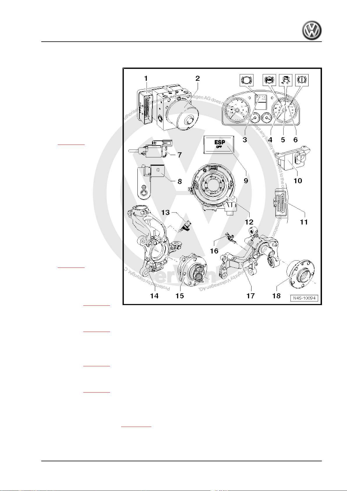
P
r
o
t
e
c
t
e
d
b
y
c
o
p
y
r
i
g
h
t
.
C
o
p
y
i
n
g
f
o
r
p
r
i
v
a
t
e
o
r
c
o
m
m
e
r
c
i
a
l
p
u
r
p
o
s
e
s
,
i
n
p
a
r
t
o
r
i
n
w
h
o
l
e
,
i
s
n
o
t
p
e
r
m
i
t
t
e
d
u
n
l
e
s
s
a
u
t
h
o
r
i
s
e
d
b
y
V
o
l
k
s
w
a
g
e
n
A
G
.
V
o
l
k
s
w
a
g
e
n
A
G
d
o
e
s
n
o
t
g
u
a
r
a
n
t
e
e
o
r
a
c
c
e
p
t
a
n
y
l
i
a
b
i
l
i
t
y
w
i
t
h
r
e
s
p
e
c
t
t
o
t
h
e
c
o
r
r
e
c
t
n
e
s
s
o
f
i
n
f
o
r
m
a
t
i
o
n
i
n
t
h
i
s
d
o
c
u
m
e
n
t
.
C
o
p
y
r
i
g
h
t
b
y
V
o
l
k
s
w
a
g
e
n
A
G
.
Eos 2006 ➤ , Golf 2004 ➤ , Golf Plus 2005 ➤ , Touran 2003 ➤
Brake systems - Edition 05.2008
4.3 ABS Mark 60 (ABS/EDL/TCS/ESP) up to week 22/2008
1 - ABS control unit -J104-
❑ Fitting location: on the
hydraulic unit on right in
engine compartment.
❑ Do not separate con‐
nector before success‐
fully completing self-di‐
agnosis. Switch ignition
off before disconnecting
connector.
❑ Removing and installing
⇒ page 42
2 - ABS hydraulic unit -N55-
❑ Fitting location: on right
in engine compartment.
The hydraulic unit consists of
the components:
❑ ABS hydraulic pump -
V64-
❑ Brake pressure sender -
G201-
❑ Valve block (includes in‐
let/outlet valves)
❑ ABS hydraulic pump -
V64- and valve block
must not be separated
from one another.
❑ Removing and installing
⇒ page 42
3 - Brake pad warning lamp -
K32-
❑ Fitting location: in dash
panel insert.
❑ Function: ⇒ page 23 .
4 - ABS warning lamp -K47-
❑ Fitting location: in dash panel insert.
❑ Function: ⇒ page 23 .
5 - ESP and TCS warning lamp -K155-
❑ Only vehicles with ABS/EDL/TCS/ESP.
❑ Fitting location: in dash panel insert.
❑ Function: ⇒ page 23 .
6 - Brake system warning lamp -K118-
❑ Fitting location: in dash panel insert.
❑ Function: ⇒ page 23 .
7 - Brake light switch -F- up to week 45/2005
❑ Including brake pedal switch -F47- .
❑ Fitting location: on brake pedal.
❑ Removing and installing ⇒ page 110
8 - Brake light switch -F- from week 45/2005
❑ Including brake pedal switch -F47- .
❑ Fitting location: on brake master cylinder.
4. Electrical/electronic components and fitting locations 19
P
r
o
t
e
c
t
e
d
b
y
c
o
p
y
r
i
g
h
t
.
C
o
p
y
i
n
g
f
o
r
p
r
i
v
a
t
e
o
r
c
o
m
m
e
r
c
i
a
l
p
u
r
p
o
s
e
s
,
i
n
p
a
r
t
o
r
i
n
w
h
o
l
e
,
i
s
n
o
t
p
e
r
m
i
t
t
e
d
u
n
l
e
s
s
a
u
t
h
o
r
i
s
e
d
b
y
V
o
l
k
s
w
a
g
e
n
A
G
.
V
o
l
k
s
w
a
g
e
n
A
G
d
o
e
s
n
o
t
g
u
a
r
a
n
t
e
e
o
r
a
c
c
e
p
t
a
n
y
l
i
a
b
i
l
i
t
y
w
i
t
h
r
e
s
p
e
c
t
t
o
t
h
e
c
o
r
r
e
c
t
n
e
s
s
o
f
i
n
f
o
r
m
a
t
i
o
n
i
n
t
h
i
s
d
o
c
u
m
e
n
t
.
C
o
p
y
r
i
g
h
t
b
y
V
o
l
k
s
w
a
g
e
n
A
G
.
Eos 2006 ➤ , Golf 2004 ➤ , Golf Plus 2005 ➤ , Touran 2003 ➤
Brake systems - Edition 05.2008
❑ Removing and installing ⇒ page 138
9 - TCS and ESP button -E256-
❑ Only vehicles with ABS/EDL/TCS/ESP.
❑ Fitting location: in centre console.
10 - ESP sensor unit -G419-
❑ Only vehicles with ABS/EDL/TCS/ESP.
❑ Fitting location in Touran: behind glove box.
❑ Fitting location in Golf and Eos: under right front seat.
❑ Combined lateral acceleration sender -G200- , yaw rate sender -G202- and longitudinal acceleration
sender -G251❑ Combined in one housing.
❑ Removing and installing (Touran) ⇒ page 60
❑ Removing and installing (Golf, Eos) ⇒ page 60 .
11 - Diagnostic connection
❑ Fitting location: driver side footwell cover.
12 - Steering angle sender -G85-
❑ Fitting location: on steering column between steering wheel and steering column switch.
❑ Removing and installing ⇒ page 61
13 - Front right/left speed sensor -G45- / -G47-
❑ Removing and installing ⇒ page 56
14 - Wheel bearing housing
15 - Wheel bearing/hub unit
❑ ABS sensor ring is installed in the wheel bearing.
16 - Rear right/left speed sensor -G44- / -G46-
Figure for front-wheel drive
❑ Removing and installing (front-wheel drive) ⇒ page 57
❑ Removing and installing (four-wheel drive) ⇒ page 58
17 - Wheel bearing housing
Figure for front-wheel drive
18 - Wheel bearing/hub unit
Figure for front-wheel drive
❑ ABS sensor ring is installed in the wheel bearing.
20 Rep. Gr.45 - Anti-lock brake system

P
r
o
t
e
c
t
e
d
b
y
c
o
p
y
r
i
g
h
t
.
C
o
p
y
i
n
g
f
o
r
p
r
i
v
a
t
e
o
r
c
o
m
m
e
r
c
i
a
l
p
u
r
p
o
s
e
s
,
i
n
p
a
r
t
o
r
i
n
w
h
o
l
e
,
i
s
n
o
t
p
e
r
m
i
t
t
e
d
u
n
l
e
s
s
a
u
t
h
o
r
i
s
e
d
b
y
V
o
l
k
s
w
a
g
e
n
A
G
.
V
o
l
k
s
w
a
g
e
n
A
G
d
o
e
s
n
o
t
g
u
a
r
a
n
t
e
e
o
r
a
c
c
e
p
t
a
n
y
l
i
a
b
i
l
i
t
y
w
i
t
h
r
e
s
p
e
c
t
t
o
t
h
e
c
o
r
r
e
c
t
n
e
s
s
o
f
i
n
f
o
r
m
a
t
i
o
n
i
n
t
h
i
s
d
o
c
u
m
e
n
t
.
C
o
p
y
r
i
g
h
t
b
y
V
o
l
k
s
w
a
g
e
n
A
G
.
Eos 2006 ➤ , Golf 2004 ➤ , Golf Plus 2005 ➤ , Touran 2003 ➤
Brake systems - Edition 05.2008
4.4 ABS Mark 60 (ABS/EDL/TCS/ESP) from week 22/2008
1 -
❑ Fitting location: on the
hydraulic unit on right in
engine compartment.
❑ Do not separate con‐
nector before success‐
fully completing self-di‐
agnosis. Switch ignition
off before disconnecting
connector.
The following components are
integrated into the control unit:
♦ Lateral acceleration sender
-G200-
♦ Yaw rate sender -G202-
♦ Longitudinal acceleration
sender -G251- (in vehicles
with four-wheel drive and
hill hold assist)
❑ Removing and installing
⇒ page 51
2 - ABS hydraulic unit -N55-
❑ Fitting location: on right
in engine compartment.
The hydraulic unit consists of
the components:
❑ ABS hydraulic pump -
V64-
❑ Brake pressure sender -
G201-
❑ Valve block (includes in‐
let/outlet valves)
❑ ABS hydraulic pump -
V64- and valve block
must not be separated from one another.
❑ Removing and installing ⇒ page 51
3 - Brake pad warning lamp -K32-
❑ Fitting location: in dash panel insert.
❑ Function: ⇒ page 23 .
4 - ABS warning lamp -K47-
❑ Fitting location: in dash panel insert.
❑ Function: ⇒ page 23 .
5 - ESP and TCS warning lamp -K155-
❑ Only vehicles with ABS/EDL/TCS/ESP.
❑ Fitting location: in dash panel insert.
❑ Function: ⇒ page 23 .
6 - Brake system warning lamp -K118-
❑ Fitting location: in dash panel insert.
❑ Function: ⇒ page 23 .
7 - Brake light switch -F-
❑ Including brake pedal switch -F47- .
4. Electrical/electronic components and fitting locations 21
P
r
o
t
e
c
t
e
d
b
y
c
o
p
y
r
i
g
h
t
.
C
o
p
y
i
n
g
f
o
r
p
r
i
v
a
t
e
o
r
c
o
m
m
e
r
c
i
a
l
p
u
r
p
o
s
e
s
,
i
n
p
a
r
t
o
r
i
n
w
h
o
l
e
,
i
s
n
o
t
p
e
r
m
i
t
t
e
d
u
n
l
e
s
s
a
u
t
h
o
r
i
s
e
d
b
y
V
o
l
k
s
w
a
g
e
n
A
G
.
V
o
l
k
s
w
a
g
e
n
A
G
d
o
e
s
n
o
t
g
u
a
r
a
n
t
e
e
o
r
a
c
c
e
p
t
a
n
y
l
i
a
b
i
l
i
t
y
w
i
t
h
r
e
s
p
e
c
t
t
o
t
h
e
c
o
r
r
e
c
t
n
e
s
s
o
f
i
n
f
o
r
m
a
t
i
o
n
i
n
t
h
i
s
d
o
c
u
m
e
n
t
.
C
o
p
y
r
i
g
h
t
b
y
V
o
l
k
s
w
a
g
e
n
A
G
.
Eos 2006 ➤ , Golf 2004 ➤ , Golf Plus 2005 ➤ , Touran 2003 ➤
Brake systems - Edition 05.2008
❑ Fitting location: on brake master cylinder.
❑ Removing and installing ⇒ page 138
8 - TCS and ESP button -E256-
❑ Only vehicles with ABS/EDL/TCS/ESP.
❑ Fitting location: in centre console.
9 - Diagnostic connection
❑ Fitting location: driver side footwell cover.
10 - Steering angle sender -G85-
Note
❑ Fitting location A: on steering column between steering wheel and steering column switch.
❑ Removing and installing ⇒ page 61
❑ Fitting location B: in steering box.
11 - Front right/left speed sensor -G45- / -G47-
❑ Removing and installing ⇒ page 56
12 - Wheel bearing/hub unit
❑ ABS sensor ring is installed in the wheel bearing.
13 - Rear right/left speed sensor -G44- / -G46-
Figure for front-wheel drive
❑ Removing and installing (front-wheel drive) ⇒ page 57
❑ Removing and installing (four-wheel drive) ⇒ page 58
14 - Wheel bearing/hub unit
Figure for front-wheel drive
❑ ABS sensor ring is installed in the wheel bearing.
22 Rep. Gr.45 - Anti-lock brake system
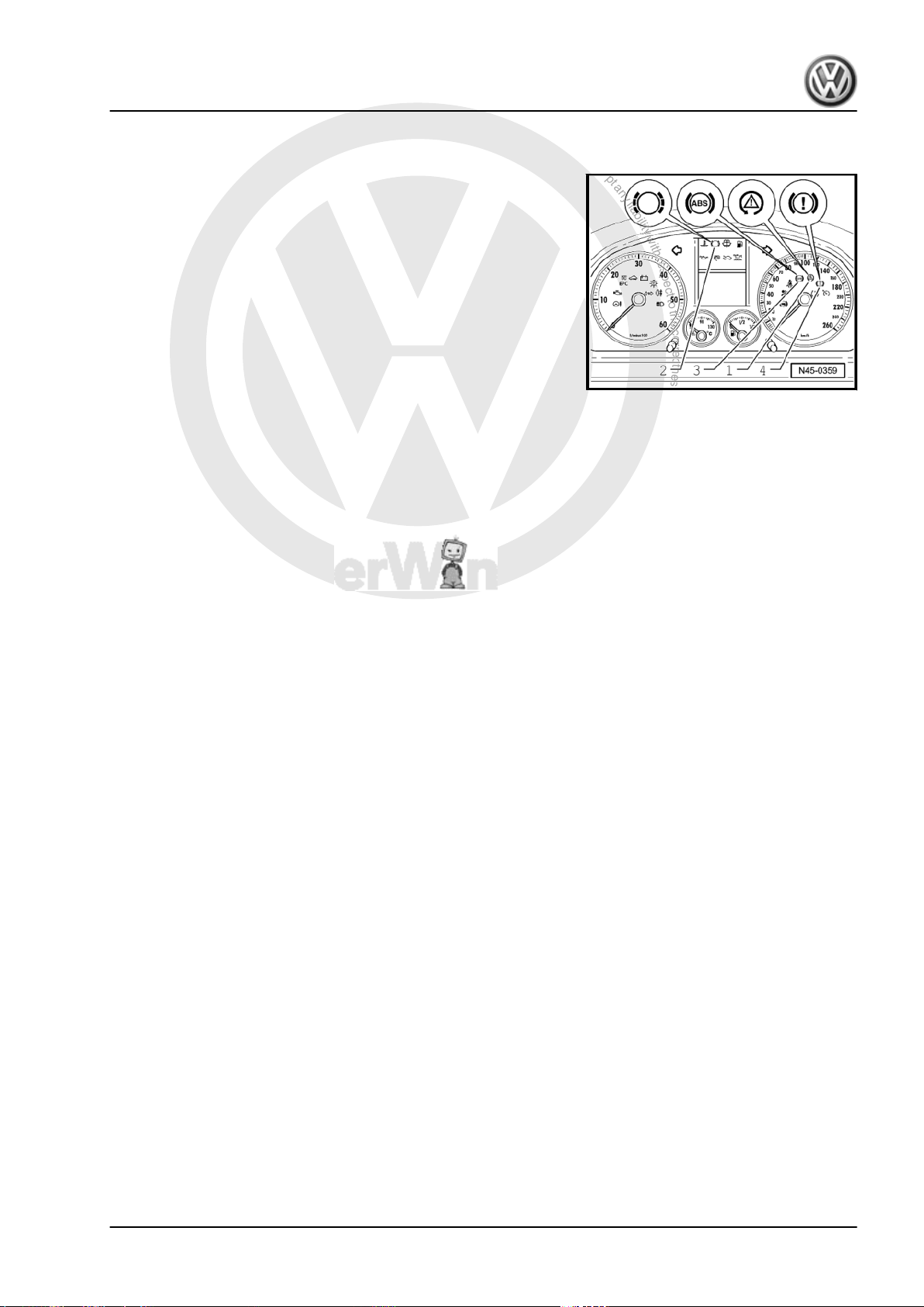
P
r
o
t
e
c
t
e
d
b
y
c
o
p
y
r
i
g
h
t
.
C
o
p
y
i
n
g
f
o
r
p
r
i
v
a
t
e
o
r
c
o
m
m
e
r
c
i
a
l
p
u
r
p
o
s
e
s
,
i
n
p
a
r
t
o
r
i
n
w
h
o
l
e
,
i
s
n
o
t
p
e
r
m
i
t
t
e
d
u
n
l
e
s
s
a
u
t
h
o
r
i
s
e
d
b
y
V
o
l
k
s
w
a
g
e
n
A
G
.
V
o
l
k
s
w
a
g
e
n
A
G
d
o
e
s
n
o
t
g
u
a
r
a
n
t
e
e
o
r
a
c
c
e
p
t
a
n
y
l
i
a
b
i
l
i
t
y
w
i
t
h
r
e
s
p
e
c
t
t
o
t
h
e
c
o
r
r
e
c
t
n
e
s
s
o
f
i
n
f
o
r
m
a
t
i
o
n
i
n
t
h
i
s
d
o
c
u
m
e
n
t
.
C
o
p
y
r
i
g
h
t
b
y
V
o
l
k
s
w
a
g
e
n
A
G
.
Eos 2006 ➤ , Golf 2004 ➤ , Golf Plus 2005 ➤ , Touran 2003 ➤
5 Fault display via warning lamps
Warning lamps, Touran
Brake systems - Edition 05.2008
5. Fault display via warning lamps 23
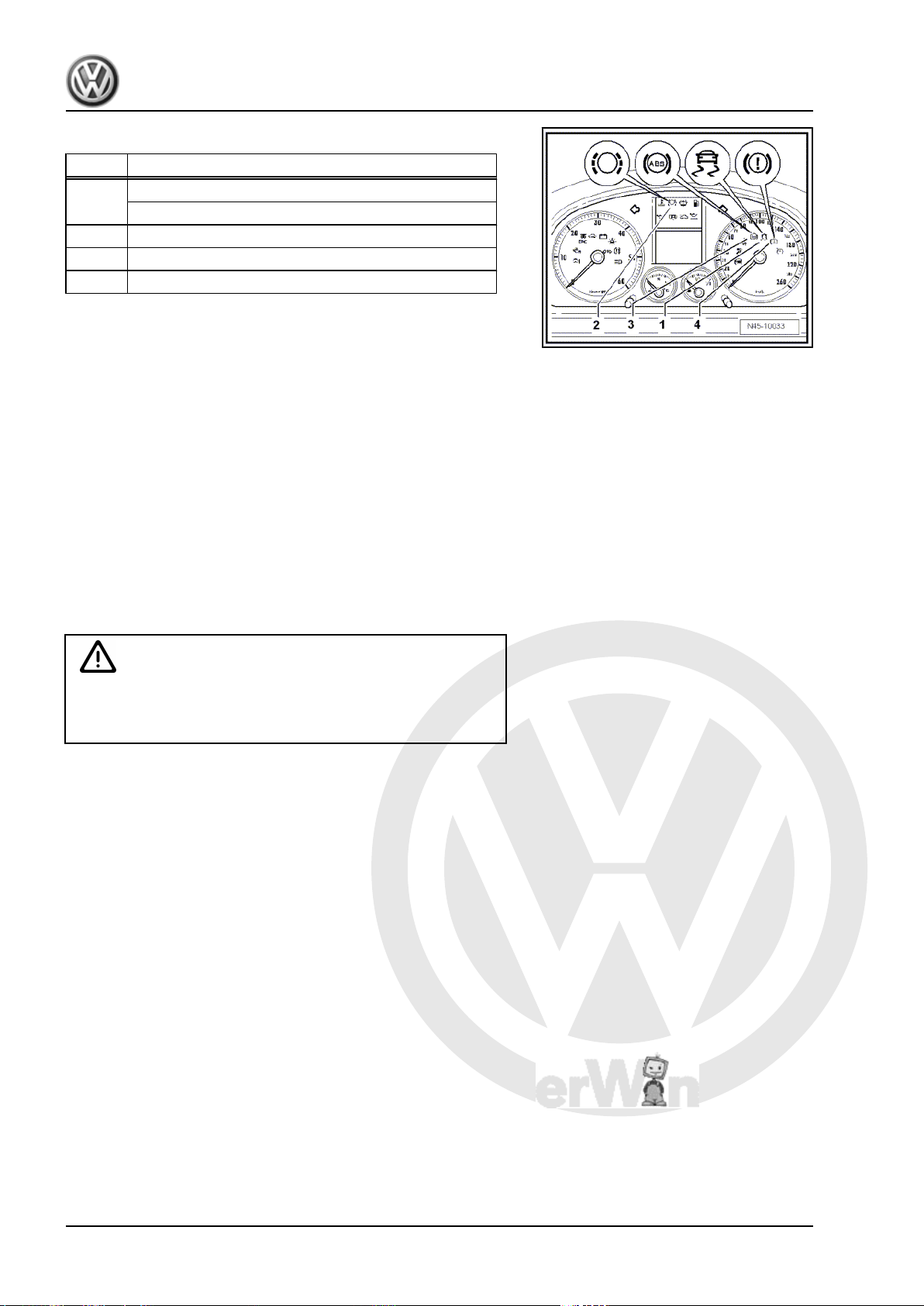
P
r
o
t
e
c
t
e
d
b
y
c
o
p
y
r
i
g
h
t
.
C
o
p
y
i
n
g
f
o
r
p
r
i
v
a
t
e
o
r
c
o
m
m
e
r
c
i
a
l
p
u
r
p
o
s
e
s
,
i
n
p
a
r
t
o
r
i
n
w
h
o
l
e
,
i
s
n
o
t
p
e
r
m
i
t
t
e
d
u
n
l
e
s
s
a
u
t
h
o
r
i
s
e
d
b
y
V
o
l
k
s
w
a
g
e
n
A
G
.
V
o
l
k
s
w
a
g
e
n
A
G
d
o
e
s
n
o
t
g
u
a
r
a
n
t
e
e
o
r
a
c
c
e
p
t
a
n
y
l
i
a
b
i
l
i
t
y
w
i
t
h
r
e
s
p
e
c
t
t
o
t
h
e
c
o
r
r
e
c
t
n
e
s
s
o
f
i
n
f
o
r
m
a
t
i
o
n
i
n
t
h
i
s
d
o
c
u
m
e
n
t
.
C
o
p
y
r
i
g
h
t
b
y
V
o
l
k
s
w
a
g
e
n
A
G
.
Eos 2006 ➤ , Golf 2004 ➤ , Golf Plus 2005 ➤ , Touran 2003 ➤
Brake systems - Edition 05.2008
Warning lamps, Golf
Item Description
1 Traction control system warning lamp -K86-
ESP and TCS warning lamp -K1552 Brake pad warning lamp -K323 ABS warning lamp -K474 Brake system warning lamp -K118-
Brake pad warning lamp -K32-
♦ If the brake pad warning lamp -K32- -2- does not go out 3 sec‐
onds after the ignition is switched on, or it comes on during
vehicle operation, the fault may be:
-a- The brake pads are worn.
Check brake pads/linings on front and rear axles. Renew worn
brake pads/linings.
-b- There is a wiring fault. ⇒ Current flow diagrams, Electrical fault
finding and Fitting locations
ABS warning lamp -K47-
♦ If the ABS warning lamp -K47- -3- does not go out after switch‐
ing ignition on and completion of test sequence then the fault
may be:
-a- The voltage supply is below 10 volts.
-b- There is a fault in the ABS.
WARNING
In the event of an ABS fault -b-, the anti-lock brake system
remains switched off, but the brake system remains fully op‐
erational.
-c- A temporary speed sensor fault occurred since the vehicle was
last started.
In this case, the ABS warning lamp will go out automatically after
the engine is restarted and the vehicle speed exceeds 20 km/h.
-d- The connection from dash panel insert to ABS control unit J104- is interrupted. ⇒ Current flow diagrams, Electrical fault
finding and Fitting locations
-e- The dash panel insert is defective.
ABS warning lamp -K47- and brake system warning lamp -K118-
♦ If the ABS warning lamp -K47- -3- goes out but the brake sys‐
tem warning lamp -K118- -4- remains on, then the fault may
be:
-a- The handbrake is applied.
-b- The brake fluid level is too low (the warning lamp flashes).
Three warning tones are audible after ignition is switched on.
-c- There is a fault in the wiring to brake system warning lamp K118- . ⇒ Current flow diagrams, Electrical fault finding and Fitting
locations
♦ If the ABS warning lamp -K47- -3- and the brake system warn‐
ing lamp -K118- -4- light up, then the ABS is defective. A
change in braking behaviour is to be reckoned with.
24 Rep. Gr.45 - Anti-lock brake system
 Loading...