


Volkswagen Golf Plus 2005 User Manual
P
r
o
t
e
c
t
e
d
b
y
c
o
p
y
r
i
g
h
t
.
C
o
p
y
i
n
g
f
o
r
p
r
i
v
a
t
e
o
r
c
o
m
m
e
r
c
i
a
l
p
u
r
p
o
s
e
s
,
i
n
p
a
r
t
o
r
i
n
w
h
o
l
e
,
i
s
n
o
t
p
e
r
m
i
t
t
e
d
u
n
l
e
s
s
a
u
t
h
o
r
i
s
e
d
b
y
V
o
l
k
s
w
a
g
e
n
A
G
.
V
o
l
k
s
w
a
g
e
n
A
G
d
o
e
s
n
o
t
g
u
a
r
a
n
t
e
e
o
r
a
c
c
e
p
t
a
n
y
l
i
a
b
i
l
i
t
y
w
i
t
h
r
e
s
p
e
c
t
t
o
t
h
e
c
o
r
r
e
c
t
n
e
s
s
o
f
i
n
f
o
r
m
a
t
i
o
n
i
n
t
h
i
s
d
o
c
u
m
e
n
t
.
C
o
p
y
r
i
g
h
t
b
y
V
o
l
k
s
w
a
g
e
n
A
G
.
Workshop Manual
Golf 2004 ➤
Golf Plus 2005 ➤
4-cylinder diesel engine (1.9 l engine)
Engine ID
BJB BKC BRU BLS BXE BXF BXJ
Edition 01.2009
Service
Service Department. Technical Information

P
r
o
t
e
c
t
e
d
b
y
c
o
p
y
r
i
g
h
t
.
C
o
p
y
i
n
g
f
o
r
p
r
i
v
a
t
e
o
r
c
o
m
m
e
r
c
i
a
l
p
u
r
p
o
s
e
s
,
i
n
p
a
r
t
o
r
i
n
w
h
o
l
e
,
i
s
n
o
t
p
e
r
m
i
t
t
e
d
u
n
l
e
s
s
a
u
t
h
o
r
i
s
e
d
b
y
V
o
l
k
s
w
a
g
e
n
A
G
.
V
o
l
k
s
w
a
g
e
n
A
G
d
o
e
s
n
o
t
g
u
a
r
a
n
t
e
e
o
r
a
c
c
e
p
t
a
n
y
l
i
a
b
i
l
i
t
y
w
i
t
h
r
e
s
p
e
c
t
t
o
t
h
e
c
o
r
r
e
c
t
n
e
s
s
o
f
i
n
f
o
r
m
a
t
i
o
n
i
n
t
h
i
s
d
o
c
u
m
e
n
t
.
C
o
p
y
r
i
g
h
t
b
y
V
o
l
k
s
w
a
g
e
n
A
G
.
List of Workshop Manual Repair GroupsList of Workshop Manual
Repair GroupsList of Workshop Manual Repair Groups
Re pa ir G ro up
00 - Technical data
10 - Removing and installing engine
13 - Crankshaft group
15 - Cylinder head, valve gear
17 - Lubrication
19 - Cooling
20 - Fuel supply system
21 - Turbocharging/supercharging
23 - Mixture preparation - injection
26 - Exhaust system
28 - Glow plug system
Technical information should always be available to the foremen and mechanics, because their
careful and constant adherence to the instructions is essential to ensure vehicle road-worthiness and
safety. In addition, the normal basic safety precautions for working on motor vehicles must, as a
matter of course, be observed.
Service
All rights reserved.
No reproduction without prior agreement from publisher.
Copyright © 2010 Volkswagen AG, Wolfsburg K0059000420

P
r
o
t
e
c
t
e
d
b
y
c
o
p
y
r
i
g
h
t
.
C
o
p
y
i
n
g
f
o
r
p
r
i
v
a
t
e
o
r
c
o
m
m
e
r
c
i
a
l
p
u
r
p
o
s
e
s
,
i
n
p
a
r
t
o
r
i
n
w
h
o
l
e
,
i
s
n
o
t
p
e
r
m
i
t
t
e
d
u
n
l
e
s
s
a
u
t
h
o
r
i
s
e
d
b
y
V
o
l
k
s
w
a
g
e
n
A
G
.
V
o
l
k
s
w
a
g
e
n
A
G
d
o
e
s
n
o
t
g
u
a
r
a
n
t
e
e
o
r
a
c
c
e
p
t
a
n
y
l
i
a
b
i
l
i
t
y
w
i
t
h
r
e
s
p
e
c
t
t
o
t
h
e
c
o
r
r
e
c
t
n
e
s
s
o
f
i
n
f
o
r
m
a
t
i
o
n
i
n
t
h
i
s
d
o
c
u
m
e
n
t
.
C
o
p
y
r
i
g
h
t
b
y
V
o
l
k
s
w
a
g
e
n
A
G
.
Contents
00 - Technical data . . . . . . . . . . . . . . . . . . . . . . . . . . . . . . . . . . . . . . . . . . . . . . . . . . . . 1
1 Technical data . . . . . . . . . . . . . . . . . . . . . . . . . . . . . . . . . . . . . . . . . . . . . . . . . . . . . . . . . . 1
1.1 Engine number . . . . . . . . . . . . . . . . . . . . . . . . . . . . . . . . . . . . . . . . . . . . . . . . . . . . . . . . . . 1
1.2 Engine data . . . . . . . . . . . . . . . . . . . . . . . . . . . . . . . . . . . . . . . . . . . . . . . . . . . . . . . . . . . . 1
10 - Removing and installing engine . . . . . . . . . . . . . . . . . . . . . . . . . . . . . . . . . . . . . . 2
1 Removing and installing engine . . . . . . . . . . . . . . . . . . . . . . . . . . . . . . . . . . . . . . . . . . . . . . 2
1.1 Removing engine . . . . . . . . . . . . . . . . . . . . . . . . . . . . . . . . . . . . . . . . . . . . . . . . . . . . . . . . 2
1.2 Securing engine to assembly stand . . . . . . . . . . . . . . . . . . . . . . . . . . . . . . . . . . . . . . . . . . 7
1.3 Notes on installing . . . . . . . . . . . . . . . . . . . . . . . . . . . . . . . . . . . . . . . . . . . . . . . . . . . . . . . . 7
1.4 Assembly mountings . . . . . . . . . . . . . . . . . . . . . . . . . . . . . . . . . . . . . . . . . . . . . . . . . . . . . . 10
13 - Crankshaft group . . . . . . . . . . . . . . . . . . . . . . . . . . . . . . . . . . . . . . . . . . . . . . . . . . 12
1 Dismantling and assembling engine . . . . . . . . . . . . . . . . . . . . . . . . . . . . . . . . . . . . . . . . . . 12
1.1 Assembly overview - poly V-belt drive . . . . . . . . . . . . . . . . . . . . . . . . . . . . . . . . . . . . . . . . 12
1.2 Removing and installing poly V-belt . . . . . . . . . . . . . . . . . . . . . . . . . . . . . . . . . . . . . . . . . . 13
1.3 Assembly overview - toothed belt drive . . . . . . . . . . . . . . . . . . . . . . . . . . . . . . . . . . . . . . . . 15
1.4 Assembly overview - crankcase . . . . . . . . . . . . . . . . . . . . . . . . . . . . . . . . . . . . . . . . . . . . . . 19
2 Removing and installing sealing flange and flywheel . . . . . . . . . . . . . . . . . . . . . . . . . . . . . . 20
2.1 Assembly overview - sealing flanges and flywheel . . . . . . . . . . . . . . . . . . . . . . . . . . . . . . 20
2.2 Renewing crankshaft oil seal - pulley end . . . . . . . . . . . . . . . . . . . . . . . . . . . . . . . . . . . . . . 21
2.3 Removing and installing sealing flange - pulley end . . . . . . . . . . . . . . . . . . . . . . . . . . . . . . 23
2.4 Renewing crankshaft sealing flange - flywheel end . . . . . . . . . . . . . . . . . . . . . . . . . . . . . . 25
2.5 Removing and installing engine speed sender G28 . . . . . . . . . . . . . . . . . . . . . . . . . . . . . . 31
3 Crankshaft . . . . . . . . . . . . . . . . . . . . . . . . . . . . . . . . . . . . . . . . . . . . . . . . . . . . . . . . . . . . . . 33
3.1 Assembly overview - crankshaft . . . . . . . . . . . . . . . . . . . . . . . . . . . . . . . . . . . . . . . . . . . . . . 33
3.2 Crankshaft dimensions . . . . . . . . . . . . . . . . . . . . . . . . . . . . . . . . . . . . . . . . . . . . . . . . . . . . 38
4 Pistons and conrods . . . . . . . . . . . . . . . . . . . . . . . . . . . . . . . . . . . . . . . . . . . . . . . . . . . . . . 39
4.1 Assembly overview - pistons and conrods . . . . . . . . . . . . . . . . . . . . . . . . . . . . . . . . . . . . . . 39
4.2 Separating new conrod . . . . . . . . . . . . . . . . . . . . . . . . . . . . . . . . . . . . . . . . . . . . . . . . . . . . 40
4.3 Checking piston projection at TDC . . . . . . . . . . . . . . . . . . . . . . . . . . . . . . . . . . . . . . . . . . . . 41
4.4 Piston and cylinder dimensions . . . . . . . . . . . . . . . . . . . . . . . . . . . . . . . . . . . . . . . . . . . . . . 42
4.5 Piston rings, cylinder bore and piston installation position . . . . . . . . . . . . . . . . . . . . . . . . . . 42
15 - Cylinder head, valve gear . . . . . . . . . . . . . . . . . . . . . . . . . . . . . . . . . . . . . . . . . . 44
1 Cylinder head . . . . . . . . . . . . . . . . . . . . . . . . . . . . . . . . . . . . . . . . . . . . . . . . . . . . . . . . . . . . 44
1.1 Assembly overview - cylinder head . . . . . . . . . . . . . . . . . . . . . . . . . . . . . . . . . . . . . . . . . . 45
1.2 Removing and installing cylinder head cover . . . . . . . . . . . . . . . . . . . . . . . . . . . . . . . . . . . . 48
1.3 Removing, installing and tensioning toothed belts . . . . . . . . . . . . . . . . . . . . . . . . . . . . . . . . 50
1.4 Removing and installing cylinder head . . . . . . . . . . . . . . . . . . . . . . . . . . . . . . . . . . . . . . . . 67
1.5 Checking compression . . . . . . . . . . . . . . . . . . . . . . . . . . . . . . . . . . . . . . . . . . . . . . . . . . . . 71
2 Valve gear . . . . . . . . . . . . . . . . . . . . . . . . . . . . . . . . . . . . . . . . . . . . . . . . . . . . . . . . . . . . . . 74
2.1 Assembly overview - valve gear . . . . . . . . . . . . . . . . . . . . . . . . . . . . . . . . . . . . . . . . . . . . . . 74
2.2 Checking valve guides . . . . . . . . . . . . . . . . . . . . . . . . . . . . . . . . . . . . . . . . . . . . . . . . . . . . 76
2.3 Renewing valve stem seals . . . . . . . . . . . . . . . . . . . . . . . . . . . . . . . . . . . . . . . . . . . . . . . . 78
2.4 Removing and installing camshaft . . . . . . . . . . . . . . . . . . . . . . . . . . . . . . . . . . . . . . . . . . . . 80
2.5 Removing and installing camshaft oil seal . . . . . . . . . . . . . . . . . . . . . . . . . . . . . . . . . . . . . . 84
17 - Lubrication . . . . . . . . . . . . . . . . . . . . . . . . . . . . . . . . . . . . . . . . . . . . . . . . . . . . . . 86
1 Engine oil . . . . . . . . . . . . . . . . . . . . . . . . . . . . . . . . . . . . . . . . . . . . . . . . . . . . . . . . . . . . . . 86
1.1 Oil capacities . . . . . . . . . . . . . . . . . . . . . . . . . . . . . . . . . . . . . . . . . . . . . . . . . . . . . . . . . . . . 86
1.2 Checking engine oil level . . . . . . . . . . . . . . . . . . . . . . . . . . . . . . . . . . . . . . . . . . . . . . . . . . 86
Golf 2004 ➤ , Golf Plus 2005 ➤
4-cylinder diesel engine (1.9 l engine) - Edition 01.2009
Contents i

P
r
o
t
e
c
t
e
d
b
y
c
o
p
y
r
i
g
h
t
.
C
o
p
y
i
n
g
f
o
r
p
r
i
v
a
t
e
o
r
c
o
m
m
e
r
c
i
a
l
p
u
r
p
o
s
e
s
,
i
n
p
a
r
t
o
r
i
n
w
h
o
l
e
,
i
s
n
o
t
p
e
r
m
i
t
t
e
d
u
n
l
e
s
s
a
u
t
h
o
r
i
s
e
d
b
y
V
o
l
k
s
w
a
g
e
n
A
G
.
V
o
l
k
s
w
a
g
e
n
A
G
d
o
e
s
n
o
t
g
u
a
r
a
n
t
e
e
o
r
a
c
c
e
p
t
a
n
y
l
i
a
b
i
l
i
t
y
w
i
t
h
r
e
s
p
e
c
t
t
o
t
h
e
c
o
r
r
e
c
t
n
e
s
s
o
f
i
n
f
o
r
m
a
t
i
o
n
i
n
t
h
i
s
d
o
c
u
m
e
n
t
.
C
o
p
y
r
i
g
h
t
b
y
V
o
l
k
s
w
a
g
e
n
A
G
.
2 Parts of lubrication system . . . . . . . . . . . . . . . . . . . . . . . . . . . . . . . . . . . . . . . . . . . . . . . . . . 87
2.1 Assembly overview - oil pump, sump . . . . . . . . . . . . . . . . . . . . . . . . . . . . . . . . . . . . . . . . . . 87
2.2 Removing and installing sump . . . . . . . . . . . . . . . . . . . . . . . . . . . . . . . . . . . . . . . . . . . . . . 88
3 Oil filter bracket, oil pressure, engine oil cooler and oil supply line . . . . . . . . . . . . . . . . . . 92
3.1 Assembly overview - oil filter bracket and engine oil cooler . . . . . . . . . . . . . . . . . . . . . . . . 92
3.2 Checking oil pressure and oil pressure switch . . . . . . . . . . . . . . . . . . . . . . . . . . . . . . . . . . 93
3.3 Assembly overview - oil supply line to turbocharger . . . . . . . . . . . . . . . . . . . . . . . . . . . . . . 94
3.4 Removing and installing oil supply line to turbocharger . . . . . . . . . . . . . . . . . . . . . . . . . . . . 95
19 - Cooling . . . . . . . . . . . . . . . . . . . . . . . . . . . . . . . . . . . . . . . . . . . . . . . . . . . . . . . . . . 97
1 Parts of cooling system . . . . . . . . . . . . . . . . . . . . . . . . . . . . . . . . . . . . . . . . . . . . . . . . . . . . 97
1.1 Parts of cooling system, body side . . . . . . . . . . . . . . . . . . . . . . . . . . . . . . . . . . . . . . . . . . . . 98
1.2 Parts of cooling system, engine side . . . . . . . . . . . . . . . . . . . . . . . . . . . . . . . . . . . . . . . . . . 99
1.3 Coolant hose schematic diagram . . . . . . . . . . . . . . . . . . . . . . . . . . . . . . . . . . . . . . . . . . . . 101
1.4 Draining and filling with coolant . . . . . . . . . . . . . . . . . . . . . . . . . . . . . . . . . . . . . . . . . . . . . . 102
1.5 Removing and installing radiator . . . . . . . . . . . . . . . . . . . . . . . . . . . . . . . . . . . . . . . . . . . . 105
1.6 Removing and installing coolant pump . . . . . . . . . . . . . . . . . . . . . . . . . . . . . . . . . . . . . . . . 106
1.7 Removing and installing thermostat . . . . . . . . . . . . . . . . . . . . . . . . . . . . . . . . . . . . . . . . . . 108
1.8 Checking cooling system for leaks . . . . . . . . . . . . . . . . . . . . . . . . . . . . . . . . . . . . . . . . . . . . 110
1.9 Checking engine oil cooler for leaks . . . . . . . . . . . . . . . . . . . . . . . . . . . . . . . . . . . . . . . . . . 112
20 - Fuel supply system . . . . . . . . . . . . . . . . . . . . . . . . . . . . . . . . . . . . . . . . . . . . . . . . 114
1 Safety precautions when working on fuel supply system . . . . . . . . . . . . . . . . . . . . . . . . . . 114
2 Rules for cleanliness . . . . . . . . . . . . . . . . . . . . . . . . . . . . . . . . . . . . . . . . . . . . . . . . . . . . . . 115
3 Fuel tank, vehicles with front-wheel drive . . . . . . . . . . . . . . . . . . . . . . . . . . . . . . . . . . . . . . 116
3.1 Assembly overview - fuel tank . . . . . . . . . . . . . . . . . . . . . . . . . . . . . . . . . . . . . . . . . . . . . . 116
3.2 Emptying fuel tank . . . . . . . . . . . . . . . . . . . . . . . . . . . . . . . . . . . . . . . . . . . . . . . . . . . . . . . . 117
3.3 Removing and installing fuel tank . . . . . . . . . . . . . . . . . . . . . . . . . . . . . . . . . . . . . . . . . . . . 121
3.4 Removing and installing fuel delivery unit . . . . . . . . . . . . . . . . . . . . . . . . . . . . . . . . . . . . . . 123
3.5 Removing and installing fuel gauge sender . . . . . . . . . . . . . . . . . . . . . . . . . . . . . . . . . . . . 124
3.6 Checking fuel pump . . . . . . . . . . . . . . . . . . . . . . . . . . . . . . . . . . . . . . . . . . . . . . . . . . . . . . 125
4 Fuel tank, vehicles with four-wheel drive . . . . . . . . . . . . . . . . . . . . . . . . . . . . . . . . . . . . . . 127
4.1 Assembly overview - fuel tank . . . . . . . . . . . . . . . . . . . . . . . . . . . . . . . . . . . . . . . . . . . . . . 127
4.2 Emptying fuel tank . . . . . . . . . . . . . . . . . . . . . . . . . . . . . . . . . . . . . . . . . . . . . . . . . . . . . . . . 128
4.3 Removing and installing fuel tank . . . . . . . . . . . . . . . . . . . . . . . . . . . . . . . . . . . . . . . . . . . . 132
4.4 Removing and installing fuel gauge sender 2 G169 . . . . . . . . . . . . . . . . . . . . . . . . . . . . . . 135
4.5 Removing and installing suction-jet pump . . . . . . . . . . . . . . . . . . . . . . . . . . . . . . . . . . . . . . 137
4.6 Checking fuel pump . . . . . . . . . . . . . . . . . . . . . . . . . . . . . . . . . . . . . . . . . . . . . . . . . . . . . . 138
5 Repairing fuel supply system . . . . . . . . . . . . . . . . . . . . . . . . . . . . . . . . . . . . . . . . . . . . . . . . 140
5.1 Assembly overview - fuel filter . . . . . . . . . . . . . . . . . . . . . . . . . . . . . . . . . . . . . . . . . . . . . . 140
5.2 Removing and installing fuel cooler . . . . . . . . . . . . . . . . . . . . . . . . . . . . . . . . . . . . . . . . . . 141
5.3 Assembly overview - accelerator mechanism . . . . . . . . . . . . . . . . . . . . . . . . . . . . . . . . . . 142
5.4 Checking tandem pump . . . . . . . . . . . . . . . . . . . . . . . . . . . . . . . . . . . . . . . . . . . . . . . . . . . . 143
5.5 Removing and installing tandem pump . . . . . . . . . . . . . . . . . . . . . . . . . . . . . . . . . . . . . . . . 147
21 - Turbocharging/supercharging . . . . . . . . . . . . . . . . . . . . . . . . . . . . . . . . . . . . . . . . 151
1 Charge air system with turbocharger . . . . . . . . . . . . . . . . . . . . . . . . . . . . . . . . . . . . . . . . . . 151
1.1 Safety precautions . . . . . . . . . . . . . . . . . . . . . . . . . . . . . . . . . . . . . . . . . . . . . . . . . . . . . . . . 151
1.2 Rules for cleanliness . . . . . . . . . . . . . . . . . . . . . . . . . . . . . . . . . . . . . . . . . . . . . . . . . . . . . . 151
1.3 Assembly overview - turbocharger . . . . . . . . . . . . . . . . . . . . . . . . . . . . . . . . . . . . . . . . . . . . 152
1.4 Removing and installing turbocharger . . . . . . . . . . . . . . . . . . . . . . . . . . . . . . . . . . . . . . . . 156
1.5 Assembly overview - parts of charge air cooling . . . . . . . . . . . . . . . . . . . . . . . . . . . . . . . . 158
1.6 Hose connections . . . . . . . . . . . . . . . . . . . . . . . . . . . . . . . . . . . . . . . . . . . . . . . . . . . . . . . . 161
1.7 Checking charge air system for leaks . . . . . . . . . . . . . . . . . . . . . . . . . . . . . . . . . . . . . . . . 162
1.8 Vacuum hose schematic diagram . . . . . . . . . . . . . . . . . . . . . . . . . . . . . . . . . . . . . . . . . . . . 164
Golf 2004 ➤ , Golf Plus 2005 ➤
4-cylinder diesel engine (1.9 l engine) - Edition 01.2009
ii Contents

P
r
o
t
e
c
t
e
d
b
y
c
o
p
y
r
i
g
h
t
.
C
o
p
y
i
n
g
f
o
r
p
r
i
v
a
t
e
o
r
c
o
m
m
e
r
c
i
a
l
p
u
r
p
o
s
e
s
,
i
n
p
a
r
t
o
r
i
n
w
h
o
l
e
,
i
s
n
o
t
p
e
r
m
i
t
t
e
d
u
n
l
e
s
s
a
u
t
h
o
r
i
s
e
d
b
y
V
o
l
k
s
w
a
g
e
n
A
G
.
V
o
l
k
s
w
a
g
e
n
A
G
d
o
e
s
n
o
t
g
u
a
r
a
n
t
e
e
o
r
a
c
c
e
p
t
a
n
y
l
i
a
b
i
l
i
t
y
w
i
t
h
r
e
s
p
e
c
t
t
o
t
h
e
c
o
r
r
e
c
t
n
e
s
s
o
f
i
n
f
o
r
m
a
t
i
o
n
i
n
t
h
i
s
d
o
c
u
m
e
n
t
.
C
o
p
y
r
i
g
h
t
b
y
V
o
l
k
s
w
a
g
e
n
A
G
.
23 - Mixture preparation - injection . . . . . . . . . . . . . . . . . . . . . . . . . . . . . . . . . . . . . . . . 166
1 Diesel direct injection system . . . . . . . . . . . . . . . . . . . . . . . . . . . . . . . . . . . . . . . . . . . . . . . . 166
1.1 Safety precautions . . . . . . . . . . . . . . . . . . . . . . . . . . . . . . . . . . . . . . . . . . . . . . . . . . . . . . . . 166
1.2 Rules for cleanliness . . . . . . . . . . . . . . . . . . . . . . . . . . . . . . . . . . . . . . . . . . . . . . . . . . . . . . 167
1.3 Assembly overview - unit injector . . . . . . . . . . . . . . . . . . . . . . . . . . . . . . . . . . . . . . . . . . . . 167
1.4 Removing and installing unit injector . . . . . . . . . . . . . . . . . . . . . . . . . . . . . . . . . . . . . . . . . . 169
1.5 Adjusting non-contact gap of unit injectors . . . . . . . . . . . . . . . . . . . . . . . . . . . . . . . . . . . . . . 171
1.6 Removing and installing O-rings for unit injector . . . . . . . . . . . . . . . . . . . . . . . . . . . . . . . . 172
1.7 Assembly overview - intake manifold . . . . . . . . . . . . . . . . . . . . . . . . . . . . . . . . . . . . . . . . . . 174
1.8 Cleaning the intake manifold flap support, Engine code BLS and BXJ . . . . . . . . . . . . . . . . 176
1.9 Assembly overview - air filter . . . . . . . . . . . . . . . . . . . . . . . . . . . . . . . . . . . . . . . . . . . . . . . . 177
2 Engine control unit . . . . . . . . . . . . . . . . . . . . . . . . . . . . . . . . . . . . . . . . . . . . . . . . . . . . . . . . 178
2.1 Reading and erasing engine control unit fault memory . . . . . . . . . . . . . . . . . . . . . . . . . . . . 178
2.2 Adapting functions and components . . . . . . . . . . . . . . . . . . . . . . . . . . . . . . . . . . . . . . . . . . 179
2.3 Removing and installing engine control unit, Golf . . . . . . . . . . . . . . . . . . . . . . . . . . . . . . . . 180
2.4 Removing and installing anti-theft engine control unit, Golf . . . . . . . . . . . . . . . . . . . . . . . . 180
2.5 Removing and installing engine control unit, Golf Plus . . . . . . . . . . . . . . . . . . . . . . . . . . . . 183
2.6 Removing and installing anti-theft engine control unit, Golf Plus . . . . . . . . . . . . . . . . . . . . 183
26 - Exhaust system . . . . . . . . . . . . . . . . . . . . . . . . . . . . . . . . . . . . . . . . . . . . . . . . . . 186
1 Exhaust system . . . . . . . . . . . . . . . . . . . . . . . . . . . . . . . . . . . . . . . . . . . . . . . . . . . . . . . . . . 186
1.1 Assembly overview - front exhaust pipe with catalytic converter . . . . . . . . . . . . . . . . . . . . 186
1.2 Assembly overview - front exhaust pipe with particulate filter . . . . . . . . . . . . . . . . . . . . . . 187
1.3 Assembly overview - silencer with mountings (vehicles with front wheel drive) . . . . . . . . . . 189
1.4 Assembly overview - silencer with mountings (vehicles with four-wheel drive) . . . . . . . . . . 191
1.5 Aligning exhaust system free of stress . . . . . . . . . . . . . . . . . . . . . . . . . . . . . . . . . . . . . . . . 192
2 Exhaust gas recirculation system . . . . . . . . . . . . . . . . . . . . . . . . . . . . . . . . . . . . . . . . . . . . 193
2.1 Assembly overview - parts of exhaust gas recirculation . . . . . . . . . . . . . . . . . . . . . . . . . . . . 193
28 - Glow plug system . . . . . . . . . . . . . . . . . . . . . . . . . . . . . . . . . . . . . . . . . . . . . . . . . . 198
1 Checking glow plug system . . . . . . . . . . . . . . . . . . . . . . . . . . . . . . . . . . . . . . . . . . . . . . . . 198
1.1 Removing, installing and checking glow plugs . . . . . . . . . . . . . . . . . . . . . . . . . . . . . . . . . . 198
1.2 Characteristics of ceramic glow plugs . . . . . . . . . . . . . . . . . . . . . . . . . . . . . . . . . . . . . . . . 199
1.3 Removing, installing and checking ceramic glow plugs . . . . . . . . . . . . . . . . . . . . . . . . . . . . 200
Golf 2004 ➤ , Golf Plus 2005 ➤
4-cylinder diesel engine (1.9 l engine) - Edition 01.2009
Contents iii

P
r
o
t
e
c
t
e
d
b
y
c
o
p
y
r
i
g
h
t
.
C
o
p
y
i
n
g
f
o
r
p
r
i
v
a
t
e
o
r
c
o
m
m
e
r
c
i
a
l
p
u
r
p
o
s
e
s
,
i
n
p
a
r
t
o
r
i
n
w
h
o
l
e
,
i
s
n
o
t
p
e
r
m
i
t
t
e
d
u
n
l
e
s
s
a
u
t
h
o
r
i
s
e
d
b
y
V
o
l
k
s
w
a
g
e
n
A
G
.
V
o
l
k
s
w
a
g
e
n
A
G
d
o
e
s
n
o
t
g
u
a
r
a
n
t
e
e
o
r
a
c
c
e
p
t
a
n
y
l
i
a
b
i
l
i
t
y
w
i
t
h
r
e
s
p
e
c
t
t
o
t
h
e
c
o
r
r
e
c
t
n
e
s
s
o
f
i
n
f
o
r
m
a
t
i
o
n
i
n
t
h
i
s
d
o
c
u
m
e
n
t
.
C
o
p
y
r
i
g
h
t
b
y
V
o
l
k
s
w
a
g
e
n
A
G
.
Golf 2004 ➤ , Golf Plus 2005 ➤
4-cylinder diesel engine (1.9 l engine) - Edition 01.2009
iv Contents
P
r
o
t
e
c
t
e
d
b
y
c
o
p
y
r
i
g
h
t
.
C
o
p
y
i
n
g
f
o
r
p
r
i
v
a
t
e
o
r
c
o
m
m
e
r
c
i
a
l
p
u
r
p
o
s
e
s
,
i
n
p
a
r
t
o
r
i
n
w
h
o
l
e
,
i
s
n
o
t
p
e
r
m
i
t
t
e
d
u
n
l
e
s
s
a
u
t
h
o
r
i
s
e
d
b
y
V
o
l
k
s
w
a
g
e
n
A
G
.
V
o
l
k
s
w
a
g
e
n
A
G
d
o
e
s
n
o
t
g
u
a
r
a
n
t
e
e
o
r
a
c
c
e
p
t
a
n
y
l
i
a
b
i
l
i
t
y
w
i
t
h
r
e
s
p
e
c
t
t
o
t
h
e
c
o
r
r
e
c
t
n
e
s
s
o
f
i
n
f
o
r
m
a
t
i
o
n
i
n
t
h
i
s
d
o
c
u
m
e
n
t
.
C
o
p
y
r
i
g
h
t
b
y
V
o
l
k
s
w
a
g
e
n
A
G
.
00 – Technical data
1 Technical data
Engine number ⇒ page 1
Engine data ⇒ page 1
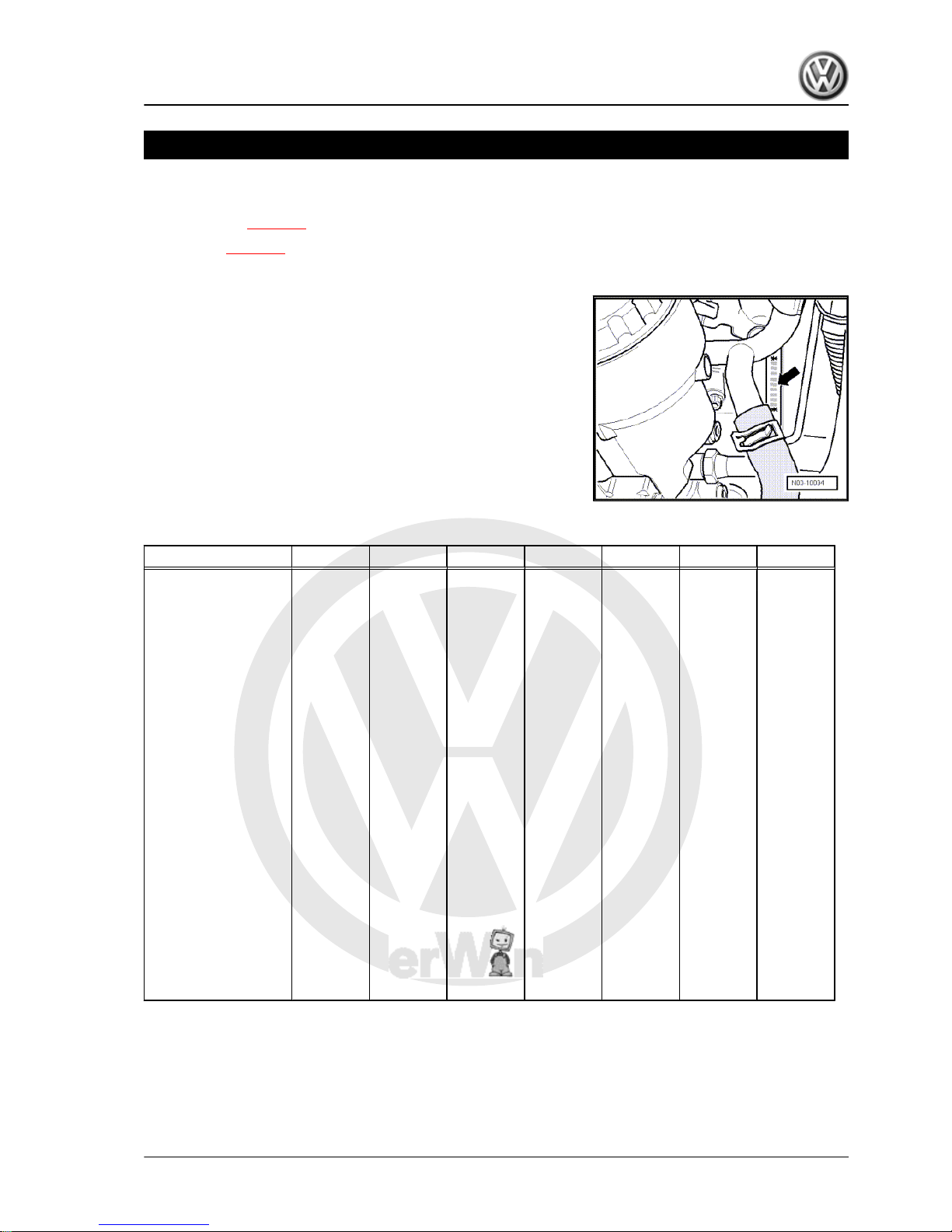
1.1 Engine number
The engine number (“code letters” and “serial number”) can be
found at the joint between engine and gearbox.
Additionally there is a sticker on the toothed belt guard with “en‐
gine code” and “serial number”.
The engine code is also included on the vehicle data sticker.
1.2 Engine data
Engine code BJB BKC BRU BLS BXE BXF BXJ
Manufactured 10.03 ▸ 10.03 ▸ 04.04 ▸ 02.06 ▸ 03.06 03.06 11.07
Emissions fulfil EU3
standard
EU4
standard
EU4
standard
EU4
standard
EU4
standard
EU4
standard
EU4
standard
Capacity l 1.9 1.9 1.9 1.9 1.9 1.9 1.9
Output kW at
rpm
77/
4000
77/
4000
66/
4000
77/
4000
77/
4000
66/
4000
66/
4000
Torque Nm at
rpm
250/
1900
250/
1900
210/
1800...250
0
250/
1900
250/
1900
210/
1800
210/
1800...250
0
Bore ∅ mm 79.5 79.5 79.5 79.5 79.5 79.5 79.5
Stroke mm 95.5 95.5 95.5 95.5 95.5 95.5 95.5
Valves per cylinder 2 2 2 2 2 2 2
Compression ratio 19.0 19.0 19.0 18.5 18.5 19.0 19.0
Fuel accord‐
ing to
DIN EN
590
DIN EN
590
DIN EN
590
DIN EN
590
DIN EN
590
DIN EN
590
DIN EN
590
Firing order
1-3-4-2 1-3-4-2 1-3-4-2 1-3-4-2 1-3-4-2 1-3-4-2 1-3-4-2
Catalytic converter yes yes yes yes yes yes yes
Exhaust gas recircu‐
lation
yes yes yes yes yes yes yes
Turbocharging/super‐
charging
yes yes yes yes yes yes yes
Charge air cooler yes yes yes yes yes yes yes
Particulate filter no no no yes no no no
Golf 2004 ➤ , Golf Plus 2005 ➤
4-cylinder diesel engine (1.9 l engine) - Edition 01.2009
1. Technical data 1
P
r
o
t
e
c
t
e
d
b
y
c
o
p
y
r
i
g
h
t
.
C
o
p
y
i
n
g
f
o
r
p
r
i
v
a
t
e
o
r
c
o
m
m
e
r
c
i
a
l
p
u
r
p
o
s
e
s
,
i
n
p
a
r
t
o
r
i
n
w
h
o
l
e
,
i
s
n
o
t
p
e
r
m
i
t
t
e
d
u
n
l
e
s
s
a
u
t
h
o
r
i
s
e
d
b
y
V
o
l
k
s
w
a
g
e
n
A
G
.
V
o
l
k
s
w
a
g
e
n
A
G
d
o
e
s
n
o
t
g
u
a
r
a
n
t
e
e
o
r
a
c
c
e
p
t
a
n
y
l
i
a
b
i
l
i
t
y
w
i
t
h
r
e
s
p
e
c
t
t
o
t
h
e
c
o
r
r
e
c
t
n
e
s
s
o
f
i
n
f
o
r
m
a
t
i
o
n
i
n
t
h
i
s
d
o
c
u
m
e
n
t
.
C
o
p
y
r
i
g
h
t
b
y
V
o
l
k
s
w
a
g
e
n
A
G
.
10 – Removing and installing engine
1 Removing and installing engine
Removing engine ⇒ page 2
Securing engine to assembly stand ⇒ page 7
Notes on installing ⇒ page 7 .
Assembly mountings ⇒ page 10 .
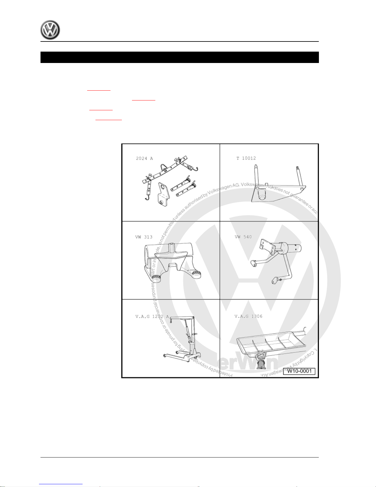
1.1 Removing engine
Special tools and workshop
equipment required
♦ Lifting tackle -2024 A-
♦ Engine bracket -T10012-
♦ Support clamp -VW 313-
♦ Engine and gearbox sup‐
port -VW 540-
♦ Workshop crane -V.A.G
1202 A-
♦ Drip tray -V.A.G 1306-
Golf 2004 ➤ , Golf Plus 2005 ➤
4-cylinder diesel engine (1.9 l engine) - Edition 01.2009
2 Rep. Gr.10 - Removing and installing engine
P
r
o
t
e
c
t
e
d
b
y
c
o
p
y
r
i
g
h
t
.
C
o
p
y
i
n
g
f
o
r
p
r
i
v
a
t
e
o
r
c
o
m
m
e
r
c
i
a
l
p
u
r
p
o
s
e
s
,
i
n
p
a
r
t
o
r
i
n
w
h
o
l
e
,
i
s
n
o
t
p
e
r
m
i
t
t
e
d
u
n
l
e
s
s
a
u
t
h
o
r
i
s
e
d
b
y
V
o
l
k
s
w
a
g
e
n
A
G
.
V
o
l
k
s
w
a
g
e
n
A
G
d
o
e
s
n
o
t
g
u
a
r
a
n
t
e
e
o
r
a
c
c
e
p
t
a
n
y
l
i
a
b
i
l
i
t
y
w
i
t
h
r
e
s
p
e
c
t
t
o
t
h
e
c
o
r
r
e
c
t
n
e
s
s
o
f
i
n
f
o
r
m
a
t
i
o
n
i
n
t
h
i
s
d
o
c
u
m
e
n
t
.
C
o
p
y
r
i
g
h
t
b
y
V
o
l
k
s
w
a
g
e
n
A
G
.
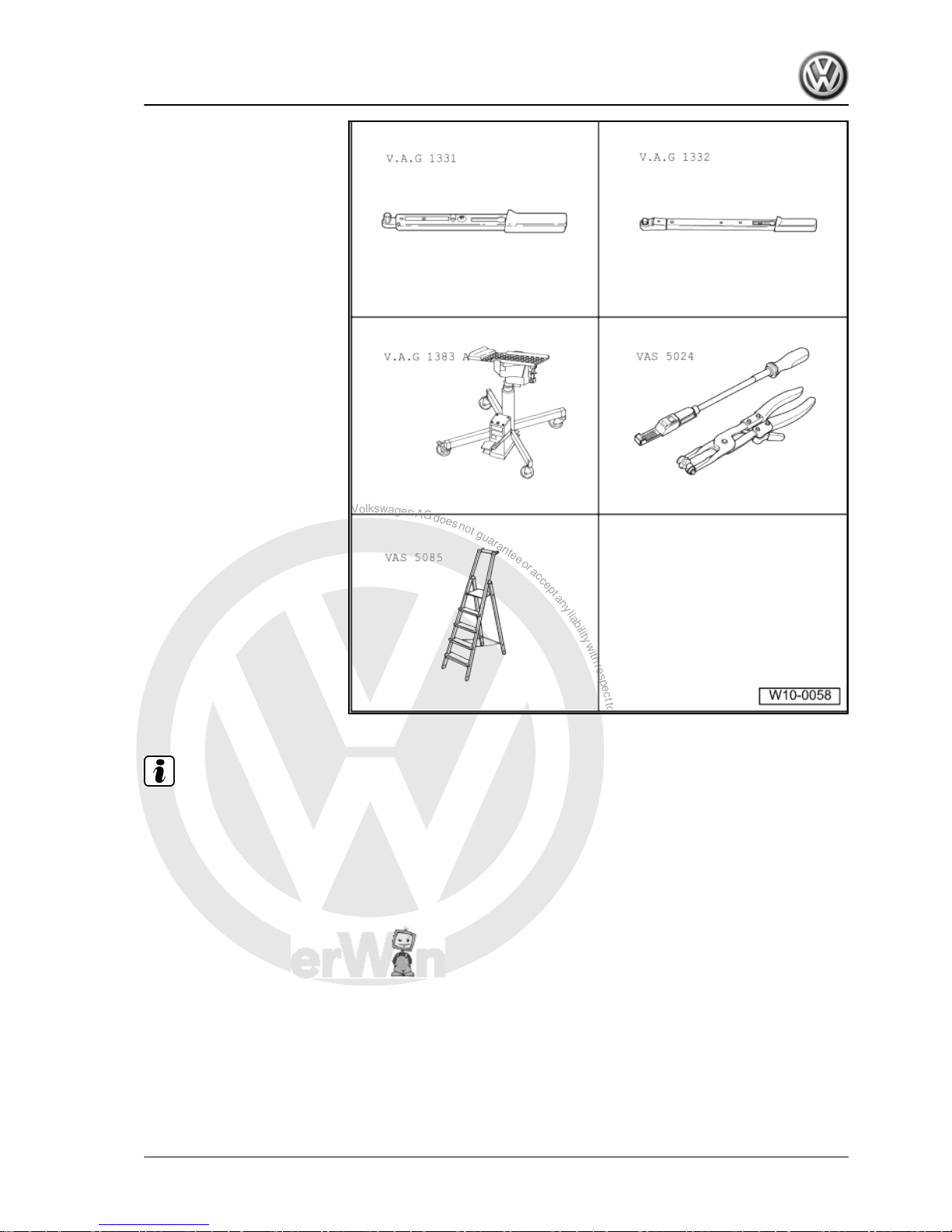
♦ Torque wrench -V.A.G
1331-
♦ Torque wrench -V.A.G
1332-
♦ Engine and gearbox jack -
V.A.G 1383 A-
♦ Spring-type clip pliers -VAS
5024-
♦ Stepladder -VAS 5085-
♦ Guide rods -T10093-
♦ Cable ties
Note
♦
Before carrying out further work, disconnect battery earth
strap. First check whether a coded radio is fitted. Obtain antitheft coding first if necessary.
♦
The engine is removed downwards together with the gearbox.
♦
All cable ties which are opened or cut through when engine is
removed must be replaced in the same position when engine
is installed.
Golf 2004 ➤ , Golf Plus 2005 ➤
4-cylinder diesel engine (1.9 l engine) - Edition 01.2009
1. Removing and installing engine 3
P
r
o
t
e
c
t
e
d
b
y
c
o
p
y
r
i
g
h
t
.
C
o
p
y
i
n
g
f
o
r
p
r
i
v
a
t
e
o
r
c
o
m
m
e
r
c
i
a
l
p
u
r
p
o
s
e
s
,
i
n
p
a
r
t
o
r
i
n
w
h
o
l
e
,
i
s
n
o
t
p
e
r
m
i
t
t
e
d
u
n
l
e
s
s
a
u
t
h
o
r
i
s
e
d
b
y
V
o
l
k
s
w
a
g
e
n
A
G
.
V
o
l
k
s
w
a
g
e
n
A
G
d
o
e
s
n
o
t
g
u
a
r
a
n
t
e
e
o
r
a
c
c
e
p
t
a
n
y
l
i
a
b
i
l
i
t
y
w
i
t
h
r
e
s
p
e
c
t
t
o
t
h
e
c
o
r
r
e
c
t
n
e
s
s
o
f
i
n
f
o
r
m
a
t
i
o
n
i
n
t
h
i
s
d
o
c
u
m
e
n
t
.
C
o
p
y
r
i
g
h
t
b
y
V
o
l
k
s
w
a
g
e
n
A
G
.
WARNING
When doing any repair work, especially in the engine compart‐
ment, pay attention to the following due to the cramped condi‐
tions:
♦ Route all the various lines (e.g. for fuel, hydraulics, acti‐
vated charcoal filter system, coolant, refrigerant, brake
fluid and vacuum) and electrical wiring in their original po‐
sitions.
♦ Ensure that there is sufficient clearance to all moving or
hot components.
Procedure
– With ignition switched off, disconnect earth strap from battery.
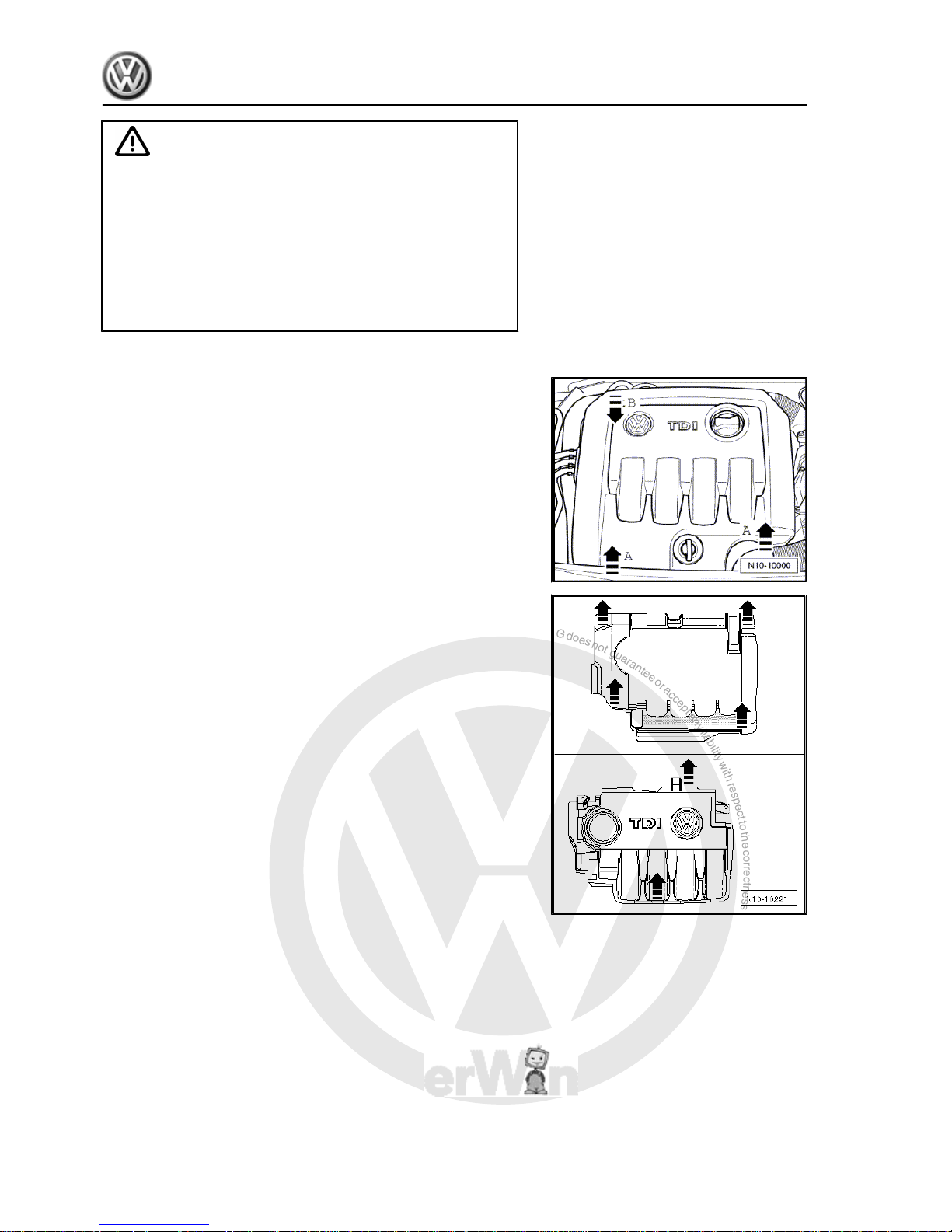
One-piece engine cover
For one-piece engine cover, pull engine cover abruptly upwards
at front and right -arrows A-, then pull forwards out of rear fas‐
tening -arrow B-.
Two-piece engine cover
For two-piece engine cover, first pull outer engine cover abruptly
upwards at -arrows-, then pull inner engine cover abruptly up‐
wards at -arrows-.
– Remove plenum chamber bulkhead. ⇒ General body repairs,
exterior; Rep. Gr. 50 ; Body - front, plenum chamber bulk‐
head .
– Remove air filter housing with air mass meter and connecting
pipe.
Golf 2004 ➤ , Golf Plus 2005 ➤
4-cylinder diesel engine (1.9 l engine) - Edition 01.2009
4 Rep. Gr.10 - Removing and installing engine
P
r
o
t
e
c
t
e
d
b
y
c
o
p
y
r
i
g
h
t
.
C
o
p
y
i
n
g
f
o
r
p
r
i
v
a
t
e
o
r
c
o
m
m
e
r
c
i
a
l
p
u
r
p
o
s
e
s
,
i
n
p
a
r
t
o
r
i
n
w
h
o
l
e
,
i
s
n
o
t
p
e
r
m
i
t
t
e
d
u
n
l
e
s
s
a
u
t
h
o
r
i
s
e
d
b
y
V
o
l
k
s
w
a
g
e
n
A
G
.
V
o
l
k
s
w
a
g
e
n
A
G
d
o
e
s
n
o
t
g
u
a
r
a
n
t
e
e
o
r
a
c
c
e
p
t
a
n
y
l
i
a
b
i
l
i
t
y
w
i
t
h
r
e
s
p
e
c
t
t
o
t
h
e
c
o
r
r
e
c
t
n
e
s
s
o
f
i
n
f
o
r
m
a
t
i
o
n
i
n
t
h
i
s
d
o
c
u
m
e
n
t
.
C
o
p
y
r
i
g
h
t
b
y
V
o
l
k
s
w
a
g
e
n
A
G
.
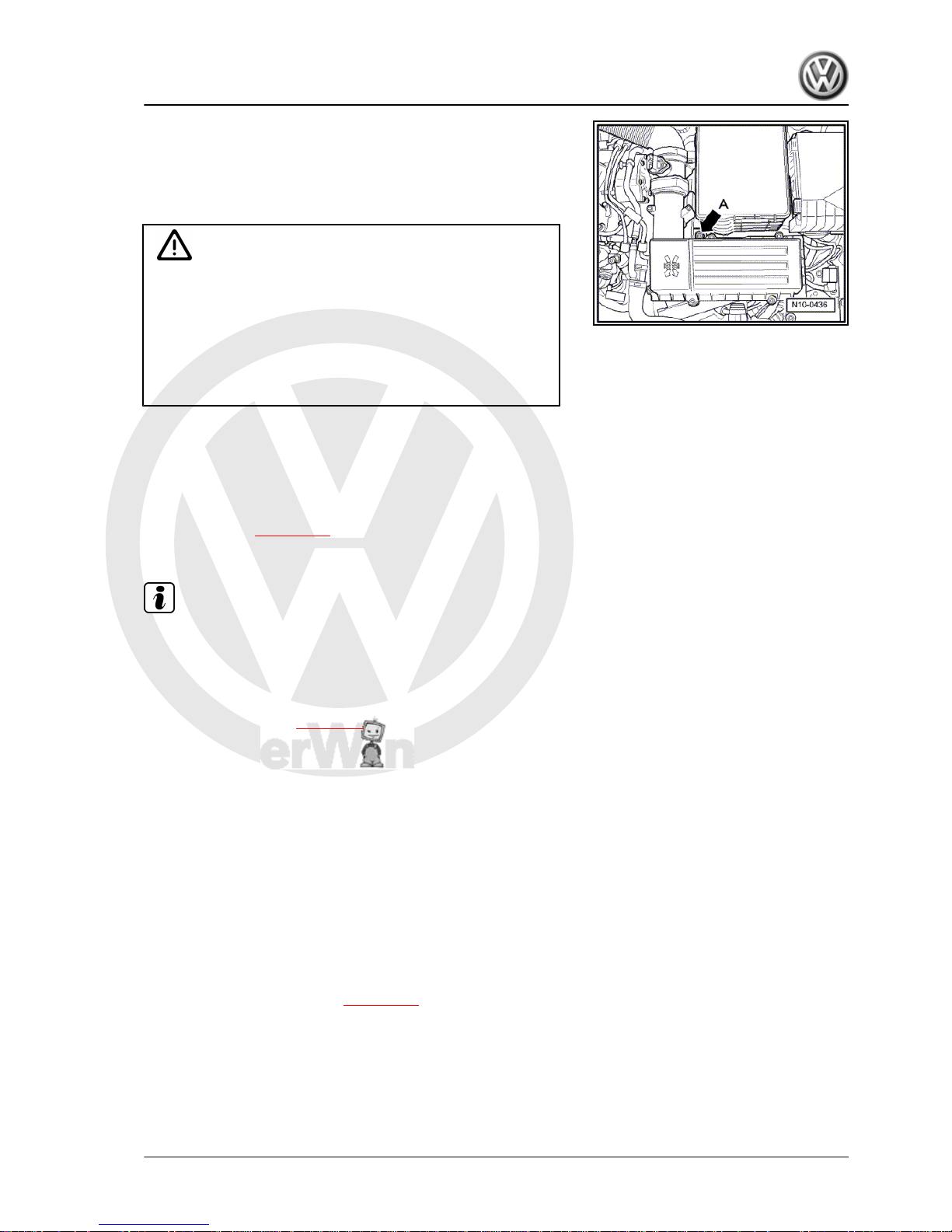
– Remove bolt -arrow A- and pull air filter housing upwards out
of mounting.
– Remove battery and battery tray.
– Disconnect fuel supply and return lines as well as coolant line
on cylinder head.
WARNING
♦ The fuel and the fuel lines in the fuel system can become
very hot (danger of scalding)!
♦ The fuel system is also under pressure! Before opening
the system, place cloths around the connections. Then
carefully loosen connection to release the pressure!
♦ Wear eye and hand protection when performing any type
of repair work on the fuel system!
– Remove insulation tray ⇒ General body repairs, exterior; Rep.
Gr. 50 ; Body - front; Assembly overview
– Bring lock carrier into service position ⇒ General body repairs,
exterior; Rep. Gr. 50 ; Body - front; Lock carrier - service po‐
sition .
– Drain coolant ⇒ page 102 .
Vehicles with air conditioner
Note
To prevent damage to condenser or to refrigerant lines/hoses,
ensure that the lines and hoses are not stretched, kinked or bent.
To facilitate removing and installing engine without opening re‐
frigerant circuit:
– Remove poly V-belt ⇒ page 13 .
– Remove air conditioner compressor ⇒ Heating, air condition‐
ing; Rep. Gr. 87 ; Removing and installing compressor brack‐
et .
– Secure air conditioner compressor to lock carrier so that re‐
frigerant lines are free of stress.
– Remove alternator ⇒ Electrical system; Rep. Gr. 27 ; Re‐
moving and installing alternator and poly V-belt .
Continuation for all vehicles
– Remove connecting pipes between charge air cooler and en‐
gine.
– Unbolt left and right-hand drive shafts from gearbox ⇒ Run‐
ning gear, axles, steering; Rep. Gr. 40 ; Removing and
installing drive shaft .
– Remove front exhaust pipe ⇒ page 186 .
– Release connectors on engine control unit and pull them off.
Golf 2004 ➤ , Golf Plus 2005 ➤
4-cylinder diesel engine (1.9 l engine) - Edition 01.2009
1. Removing and installing engine 5
P
r
o
t
e
c
t
e
d
b
y
c
o
p
y
r
i
g
h
t
.
C
o
p
y
i
n
g
f
o
r
p
r
i
v
a
t
e
o
r
c
o
m
m
e
r
c
i
a
l
p
u
r
p
o
s
e
s
,
i
n
p
a
r
t
o
r
i
n
w
h
o
l
e
,
i
s
n
o
t
p
e
r
m
i
t
t
e
d
u
n
l
e
s
s
a
u
t
h
o
r
i
s
e
d
b
y
V
o
l
k
s
w
a
g
e
n
A
G
.
V
o
l
k
s
w
a
g
e
n
A
G
d
o
e
s
n
o
t
g
u
a
r
a
n
t
e
e
o
r
a
c
c
e
p
t
a
n
y
l
i
a
b
i
l
i
t
y
w
i
t
h
r
e
s
p
e
c
t
t
o
t
h
e
c
o
r
r
e
c
t
n
e
s
s
o
f
i
n
f
o
r
m
a
t
i
o
n
i
n
t
h
i
s
d
o
c
u
m
e
n
t
.
C
o
p
y
r
i
g
h
t
b
y
V
o
l
k
s
w
a
g
e
n
A
G
.
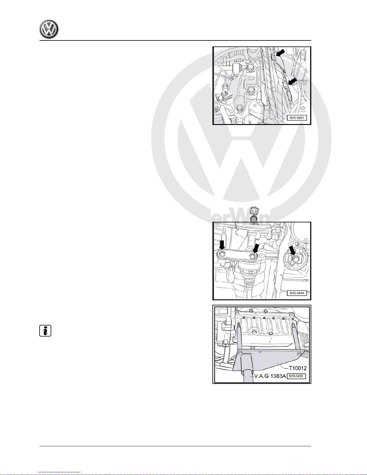
– Open all cable guide fasteners -arrows-.
– Remove wiring harness from cable guide on longitudinal mem‐
ber and lay to side on engine.
– Pull off or disconnect all other electrical connections from en‐
gine and gearbox as necessary and lay to side.
– Separate all connecting, coolant, vacuum and intake hoses
from engine.
Vehicles with manual gearbox
– Remove slave cylinder for hydraulic clutch. ⇒ 6-speed manual
gearbox 02S; Rep. Gr. 30 ; Repairing clutch mechanism; As‐
sembly overview - hydraulics .
– Unbolt gear selector mechanism from gearbox. ⇒ 6-speed
manual gearbox 02S; Rep. Gr. 34 ; Repairing selector mech‐
anism .
Vehicles with four-wheel drive:
– Remove selector mechanism from gearbox ⇒ 6-speed man‐
ual gearbox 02Q, four-wheel drive; Rep. Gr. 34 ; Repairing
selector mechanism .
– Separate pressure line for hydraulic clutch control.
– Remove front propshaft ⇒ Final drive 02D, 0AV; Rep. Gr. 39 ;
Assembly overview - repairing propshaft .
Continuation for all vehicles:
– Unbolt pendulum support -arrows-.
Vehicles with particulate filter
– Remove subframe ⇒ Running gear, axles, steering; Rep. Gr.
40 ; Removing and installing subframe .
– Remove right drive shaft ⇒ Running gear, axles, steering;
Rep. Gr. 40 ; Removing and installing drive shafts .
– Remove steering box ⇒ Running gear, axles, steering; Rep.
Gr. 48 ; Removing and installing steering box .
Continuation for all vehicles:
– Insert engine bracket -T10012- in engine and gearbox jack -
V.A.G 1383 A- .
Note
Support pins must be secured to engine bracket -T10012- as
shown.
– Fit engine bracket -T10012- to cylinder block with M10 x 25/
8.8 bolt and tighten to approx. 40 Nm.
– Raise engine and gearbox slightly using engine and gearbox
jack -V.A.G 1383 A- .
Golf 2004 ➤ , Golf Plus 2005 ➤
4-cylinder diesel engine (1.9 l engine) - Edition 01.2009
6 Rep. Gr.10 - Removing and installing engine
P
r
o
t
e
c
t
e
d
b
y
c
o
p
y
r
i
g
h
t
.
C
o
p
y
i
n
g
f
o
r
p
r
i
v
a
t
e
o
r
c
o
m
m
e
r
c
i
a
l
p
u
r
p
o
s
e
s
,
i
n
p
a
r
t
o
r
i
n
w
h
o
l
e
,
i
s
n
o
t
p
e
r
m
i
t
t
e
d
u
n
l
e
s
s
a
u
t
h
o
r
i
s
e
d
b
y
V
o
l
k
s
w
a
g
e
n
A
G
.
V
o
l
k
s
w
a
g
e
n
A
G
d
o
e
s
n
o
t
g
u
a
r
a
n
t
e
e
o
r
a
c
c
e
p
t
a
n
y
l
i
a
b
i
l
i
t
y
w
i
t
h
r
e
s
p
e
c
t
t
o
t
h
e
c
o
r
r
e
c
t
n
e
s
s
o
f
i
n
f
o
r
m
a
t
i
o
n
i
n
t
h
i
s
d
o
c
u
m
e
n
t
.
C
o
p
y
r
i
g
h
t
b
y
V
o
l
k
s
w
a
g
e
n
A
G
.
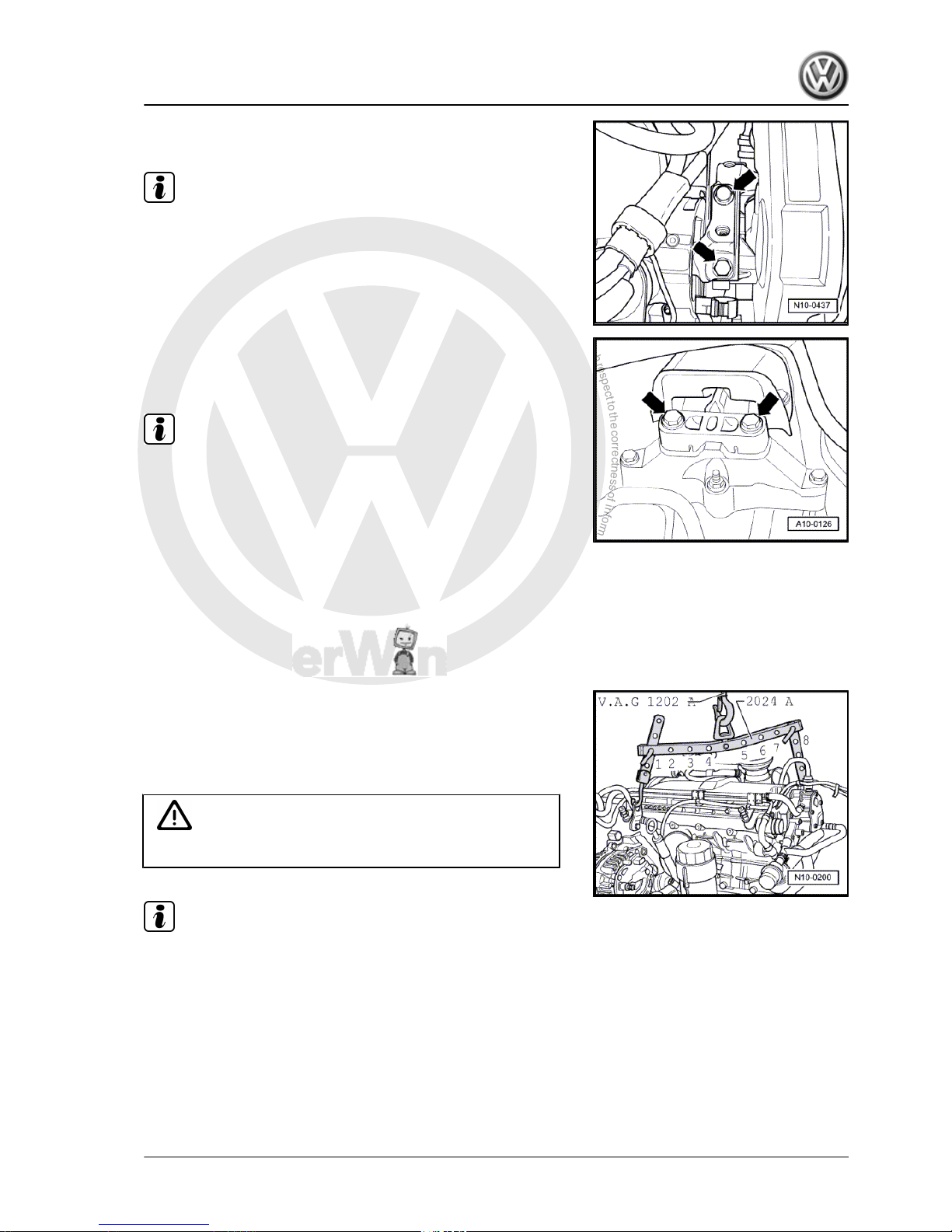
– Unbolt assembly mounting on engine side from engine bracket
-arrows-.
Note
To remove securing bolts, use stepladder -VAS 5085- .
– Unbolt assembly mounting on gearbox side from gearbox
bracket -arrows-.
– Carefully lower engine with gearbox.
Note
Engine with gearbox must be guided carefully when lowered to
prevent damage to bodywork.
1.2 Securing engine to assembly stand
When working on the engine, secure it to support clamp -VW 313of the assembly stand using engine and gearbox support -VW
540- .
Procedure
– Disconnect gearbox.
– Attach lifting tackle -2024 A- as shown and raise engine out of
engine and gearbox jack -V.A.G 1383 A- using workshop hoist
-V.A.G 1202 A- .
Pulley end: 2nd hole in hook rail at position 1
Flywheel end: 4th hole in hook at position 8
WARNING
The hooks and locating pins must be secured with locking pins.
Note
♦
The positions marked 1...4 on the bar must be towards the
pulley end.
♦
The holes in the hook rails are counted up from the hook.
– Secure engine on support clamp -VW 313- using engine and
gearbox jack -VW 540- .
1.3 Notes on installing
Installation is carried out in the reverse order. When installing,
note the following:
Golf 2004 ➤ , Golf Plus 2005 ➤
4-cylinder diesel engine (1.9 l engine) - Edition 01.2009
1. Removing and installing engine 7
P
r
o
t
e
c
t
e
d
b
y
c
o
p
y
r
i
g
h
t
.
C
o
p
y
i
n
g
f
o
r
p
r
i
v
a
t
e
o
r
c
o
m
m
e
r
c
i
a
l
p
u
r
p
o
s
e
s
,
i
n
p
a
r
t
o
r
i
n
w
h
o
l
e
,
i
s
n
o
t
p
e
r
m
i
t
t
e
d
u
n
l
e
s
s
a
u
t
h
o
r
i
s
e
d
b
y
V
o
l
k
s
w
a
g
e
n
A
G
.
V
o
l
k
s
w
a
g
e
n
A
G
d
o
e
s
n
o
t
g
u
a
r
a
n
t
e
e
o
r
a
c
c
e
p
t
a
n
y
l
i
a
b
i
l
i
t
y
w
i
t
h
r
e
s
p
e
c
t
t
o
t
h
e
c
o
r
r
e
c
t
n
e
s
s
o
f
i
n
f
o
r
m
a
t
i
o
n
i
n
t
h
i
s
d
o
c
u
m
e
n
t
.
C
o
p
y
r
i
g
h
t
b
y
V
o
l
k
s
w
a
g
e
n
A
G
.
– Check clutch release bearing for wear and renew if necessary.
– Lubricate splines of input shaft lightly with G 000 100.
– Check whether dowel sleeves for centring engine and gearbox
are in cylinder block and install if necessary.
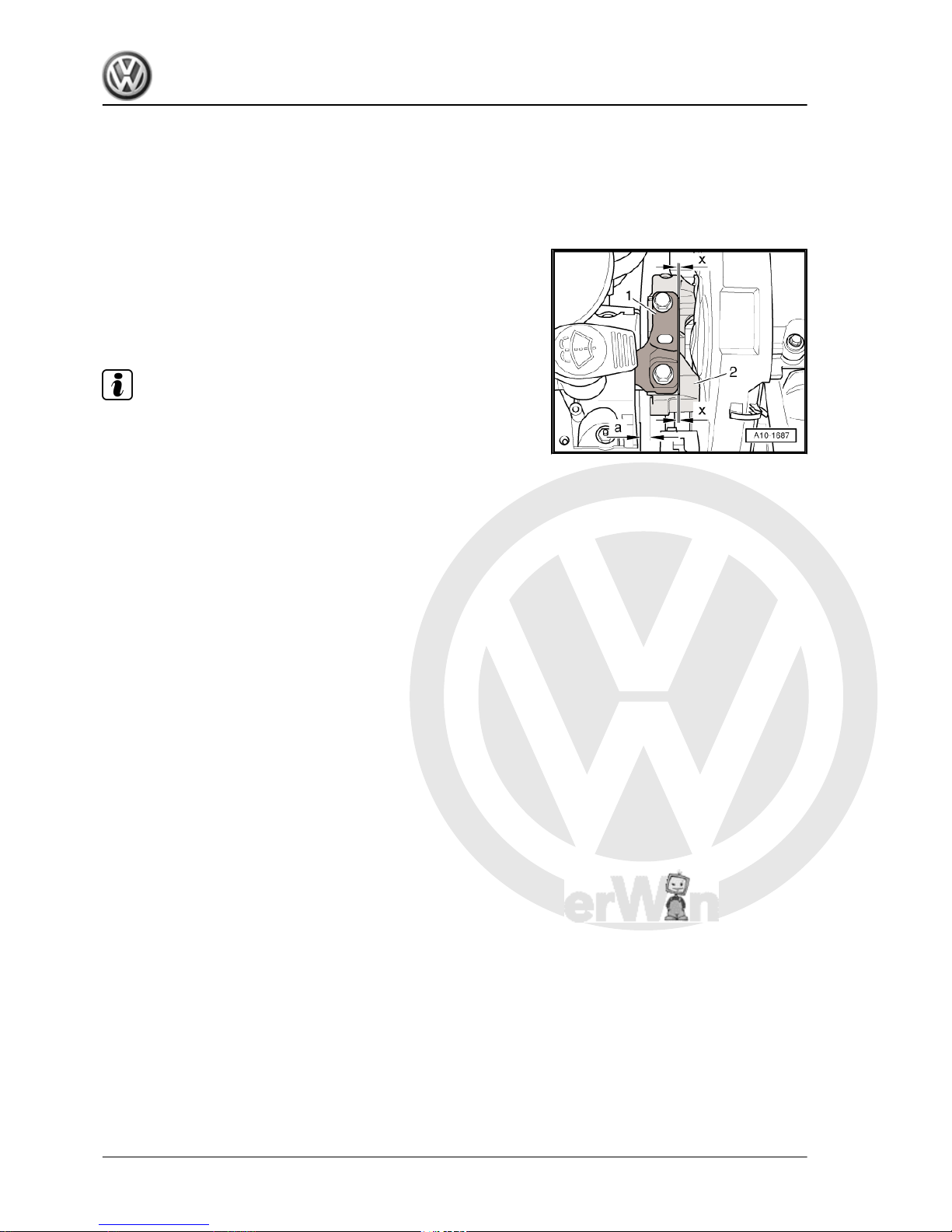
When installing engine, ensure correct position of assembly
mountings:
– On belt pulley side, ensure that there is a distance -a- of at
least 10 mm between engine support and right longitudinal
member.
– The side surface of the engine support -2- should be located
parallel to the support arm -1-. Dimension -x- must be identical
at top and bottom.
Note
Distance -a- = 10 mm can also be checked with a metal rod of
suitable size, or similar.
Golf 2004 ➤ , Golf Plus 2005 ➤
4-cylinder diesel engine (1.9 l engine) - Edition 01.2009
8 Rep. Gr.10 - Removing and installing engine
P
r
o
t
e
c
t
e
d
b
y
c
o
p
y
r
i
g
h
t
.
C
o
p
y
i
n
g
f
o
r
p
r
i
v
a
t
e
o
r
c
o
m
m
e
r
c
i
a
l
p
u
r
p
o
s
e
s
,
i
n
p
a
r
t
o
r
i
n
w
h
o
l
e
,
i
s
n
o
t
p
e
r
m
i
t
t
e
d
u
n
l
e
s
s
a
u
t
h
o
r
i
s
e
d
b
y
V
o
l
k
s
w
a
g
e
n
A
G
.
V
o
l
k
s
w
a
g
e
n
A
G
d
o
e
s
n
o
t
g
u
a
r
a
n
t
e
e
o
r
a
c
c
e
p
t
a
n
y
l
i
a
b
i
l
i
t
y
w
i
t
h
r
e
s
p
e
c
t
t
o
t
h
e
c
o
r
r
e
c
t
n
e
s
s
o
f
i
n
f
o
r
m
a
t
i
o
n
i
n
t
h
i
s
d
o
c
u
m
e
n
t
.
C
o
p
y
r
i
g
h
t
b
y
V
o
l
k
s
w
a
g
e
n
A
G
.
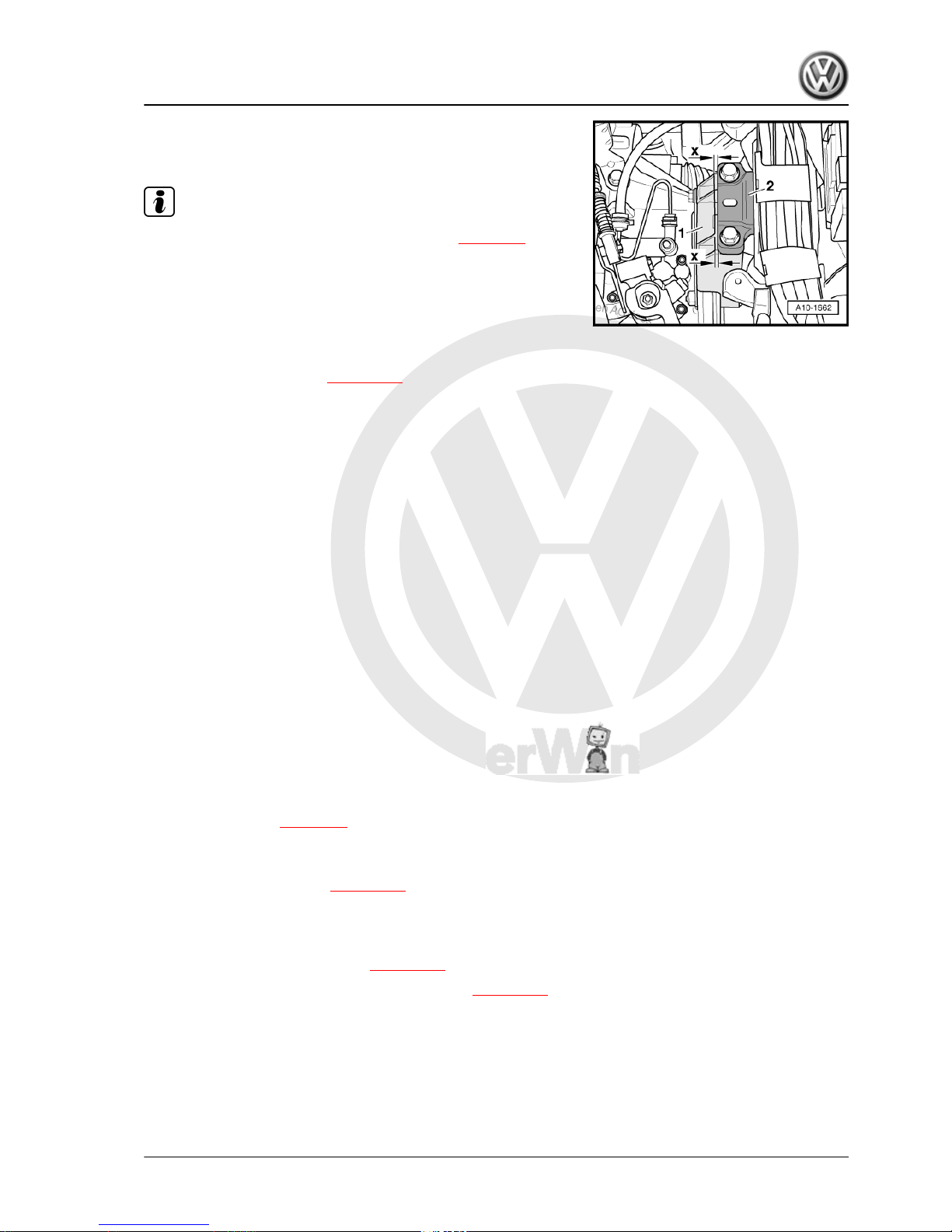
– Ensure that the edges of the support arm on the gearbox as‐
sembly mounting -2- and gearbox support -1- are parallel.
Dimension -x- must be identical at top and bottom.
Note
♦
Torque specifications for assembly mounting ⇒ page 10 .
♦
Electrical connections and routing. ⇒ Electrical system; Rep.
Gr. 97
– Install pendulum support.
– Install drive shafts ⇒ Running gear, axles, steering; Rep. Gr.
40 ; Removing and installing drive shafts .
– Install front exhaust pipe ⇒ page 186 .
Vehicles with manual gearbox
– Install slave cylinder for hydraulic clutch ⇒ 6-speed manual
gearbox 02S; Rep. Gr. 30 ; Repairing clutch mechanism; As‐
sembly overview - hydraulics .
– Remove selector mechanism from gearbox ⇒ 6-speed man‐
ual gearbox 02S; Rep. Gr. 34 ; Repairing selector mecha‐
nism .
Vehicles with four-wheel drive:
– Install selector mechanism on gearbox ⇒ 6-speed manual
gearbox 02Q, four-wheel drive; Rep. Gr. 34 ; Repairing se‐
lector mechanism .
– Install pressure line for hydraulic clutch control.
– Install front propshaft ⇒ Final drive 02D, 0AV; Rep. Gr. 39 ;
Assembly overview - repairing propshaft .
Continuation for all vehicles:
– On vehicles with particulate filter install subframe ⇒ Running
gear, axles, steering; Rep. Gr. 40
– Install alternator ⇒ Electrical system; Rep. Gr. 27 ; Removing
and installing alternator and poly V- belt .
– Install air conditioner compressor ⇒ Heating, air conditioning;
Rep. Gr. 87 ; Removing and installing compressor bracket.
– Install poly V-belt ⇒ page 13 .
– Install insulation tray ⇒ General body repairs, exterior; Rep.
Gr. 50 ; Body - front; Assembly overview.
– Install engine control unit ⇒ page 178 .
– Install plenum chamber bulkhead ⇒ General body repairs,
exterior; Rep. Gr. 50 ; Body - front; Plenum chamber bulk‐
head .
– Fill cooling system with coolant ⇒ page 102 .
– Carry out road test and then read fault memory ⇒ page 178 .
Golf 2004 ➤ , Golf Plus 2005 ➤
4-cylinder diesel engine (1.9 l engine) - Edition 01.2009
1. Removing and installing engine 9
P
r
o
t
e
c
t
e
d
b
y
c
o
p
y
r
i
g
h
t
.
C
o
p
y
i
n
g
f
o
r
p
r
i
v
a
t
e
o
r
c
o
m
m
e
r
c
i
a
l
p
u
r
p
o
s
e
s
,
i
n
p
a
r
t
o
r
i
n
w
h
o
l
e
,
i
s
n
o
t
p
e
r
m
i
t
t
e
d
u
n
l
e
s
s
a
u
t
h
o
r
i
s
e
d
b
y
V
o
l
k
s
w
a
g
e
n
A
G
.
V
o
l
k
s
w
a
g
e
n
A
G
d
o
e
s
n
o
t
g
u
a
r
a
n
t
e
e
o
r
a
c
c
e
p
t
a
n
y
l
i
a
b
i
l
i
t
y
w
i
t
h
r
e
s
p
e
c
t
t
o
t
h
e
c
o
r
r
e
c
t
n
e
s
s
o
f
i
n
f
o
r
m
a
t
i
o
n
i
n
t
h
i
s
d
o
c
u
m
e
n
t
.
C
o
p
y
r
i
g
h
t
b
y
V
o
l
k
s
w
a
g
e
n
A
G
.
Specified torques
Threaded connection
Specified torque
Bolts, nuts M6 10 Nm
M8 20 Nm
M10 45 Nm
M12 60 Nm
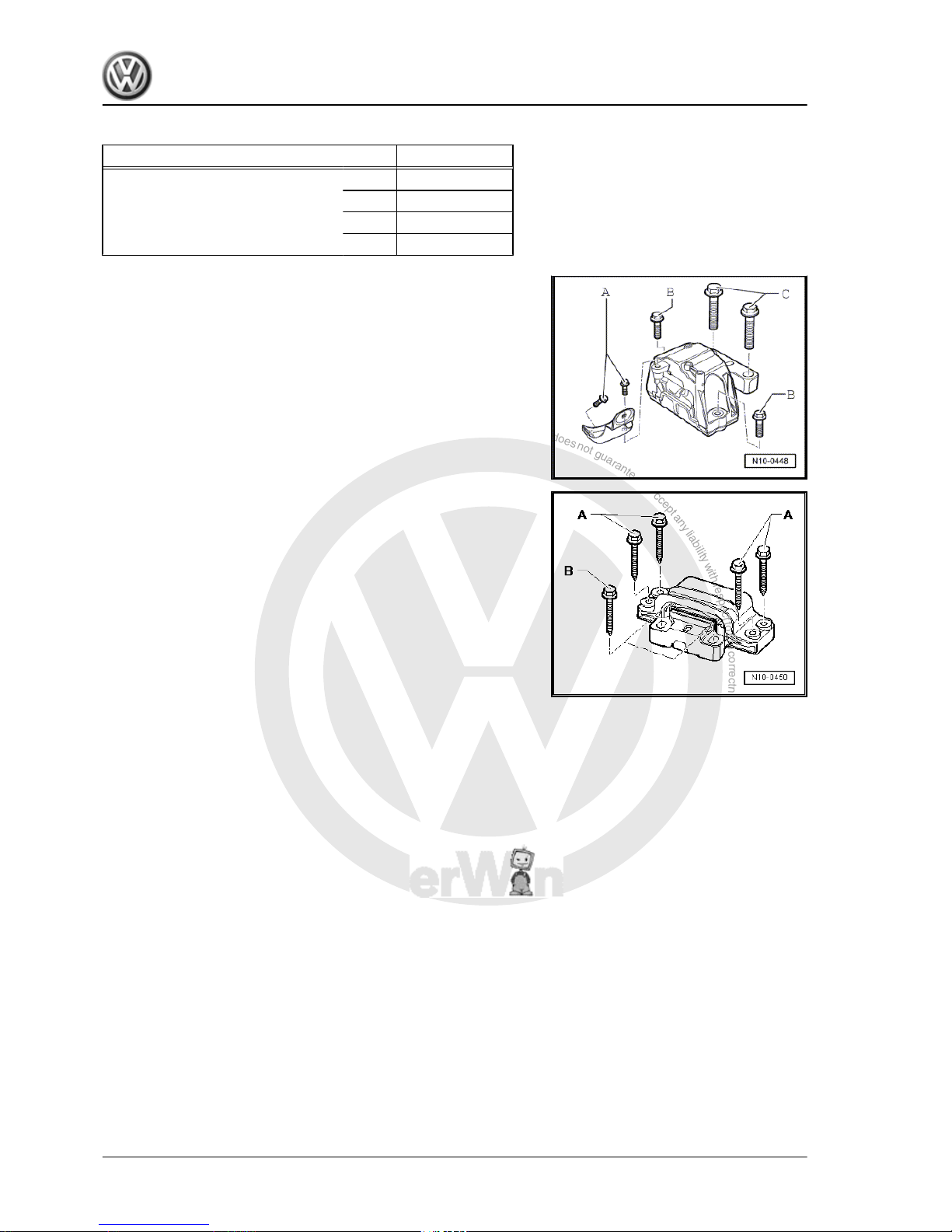
1.4 Assembly mountings
Engine assembly mounting
A = 20 Nm + 90° (1/4 turn) further
1)
B = 40 Nm + 90° (1/4 turn) further
1)
C = 60 Nm + 90° (1/4 turn) further
1)
1)
Renew
Gearbox assembly mounting
A = 40 Nm + 90° (1/4 turn) further
1)
B = 60 Nm + 90° (1/4 turn) further
1)
1)
Renew
Golf 2004 ➤ , Golf Plus 2005 ➤
4-cylinder diesel engine (1.9 l engine) - Edition 01.2009
10 Rep. Gr.10 - Removing and installing engine
P
r
o
t
e
c
t
e
d
b
y
c
o
p
y
r
i
g
h
t
.
C
o
p
y
i
n
g
f
o
r
p
r
i
v
a
t
e
o
r
c
o
m
m
e
r
c
i
a
l
p
u
r
p
o
s
e
s
,
i
n
p
a
r
t
o
r
i
n
w
h
o
l
e
,
i
s
n
o
t
p
e
r
m
i
t
t
e
d
u
n
l
e
s
s
a
u
t
h
o
r
i
s
e
d
b
y
V
o
l
k
s
w
a
g
e
n
A
G
.
V
o
l
k
s
w
a
g
e
n
A
G
d
o
e
s
n
o
t
g
u
a
r
a
n
t
e
e
o
r
a
c
c
e
p
t
a
n
y
l
i
a
b
i
l
i
t
y
w
i
t
h
r
e
s
p
e
c
t
t
o
t
h
e
c
o
r
r
e
c
t
n
e
s
s
o
f
i
n
f
o
r
m
a
t
i
o
n
i
n
t
h
i
s
d
o
c
u
m
e
n
t
.
C
o
p
y
r
i
g
h
t
b
y
V
o
l
k
s
w
a
g
e
n
A
G
.
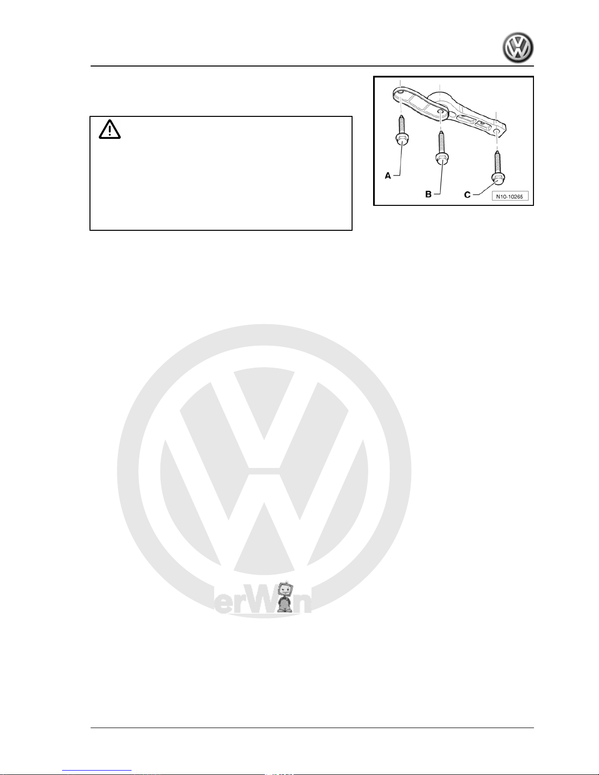
Pendulum support
Always note the size and strength class of bolt. Different specified
torques are valid.
Caution
From model year 08, in manual gearboxes 02Q Heli Coil in‐
serts are installed in the threaded connections to pendulum
support. Difference ⇒ Rep. Gr. 34
For these and all other gearboxes bolts with strength class 10.9
must be used.
If Heli Coil inserts are not fitted in manual gearboxes 02Q, use
bolts with strength class 8.8 and the specified torques.
Bolt -A-
M10 x 35 strength class 8.8: turn 40 Nm + 90° further
M10 x 35 strength class 10.9: turn 50 Nm + 90° further
Always renew after removing
Bolt -B-
M10 x 75 strength class 8.8: turn 40 Nm + 90° further
M10 x 75 strength class 10.9: turn 50 Nm + 90° further
Always renew after removing
Bolt -C-
M14 x 1.5 x 70
100 Nm + turn 90° further
Tighten only if pendulum support is bolted to gearbox
Always renew after removing
Golf 2004 ➤ , Golf Plus 2005 ➤
4-cylinder diesel engine (1.9 l engine) - Edition 01.2009
1. Removing and installing engine 11
P
r
o
t
e
c
t
e
d
b
y
c
o
p
y
r
i
g
h
t
.
C
o
p
y
i
n
g
f
o
r
p
r
i
v
a
t
e
o
r
c
o
m
m
e
r
c
i
a
l
p
u
r
p
o
s
e
s
,
i
n
p
a
r
t
o
r
i
n
w
h
o
l
e
,
i
s
n
o
t
p
e
r
m
i
t
t
e
d
u
n
l
e
s
s
a
u
t
h
o
r
i
s
e
d
b
y
V
o
l
k
s
w
a
g
e
n
A
G
.
V
o
l
k
s
w
a
g
e
n
A
G
d
o
e
s
n
o
t
g
u
a
r
a
n
t
e
e
o
r
a
c
c
e
p
t
a
n
y
l
i
a
b
i
l
i
t
y
w
i
t
h
r
e
s
p
e
c
t
t
o
t
h
e
c
o
r
r
e
c
t
n
e
s
s
o
f
i
n
f
o
r
m
a
t
i
o
n
i
n
t
h
i
s
d
o
c
u
m
e
n
t
.
C
o
p
y
r
i
g
h
t
b
y
V
o
l
k
s
w
a
g
e
n
A
G
.
13 – Crankshaft group
1 Dismantling and assembling engine
Assembly overview - poly V-belt drive ⇒ page 12
Removing and installing poly V-belt ⇒ page 13
Assembly overview - toothed belt drive ⇒ page 15
Assembly overview - crankcase ⇒ page 19
Note
If large quantities of metal particles or other deposits (caused, for
example, by partial seizure of the crankshaft or conrod bearings)
are found in the engine oil when making repairs, clean the oil
passages thoroughly and renew the engine oil cooler in order to
prevent further damage from occurring later.
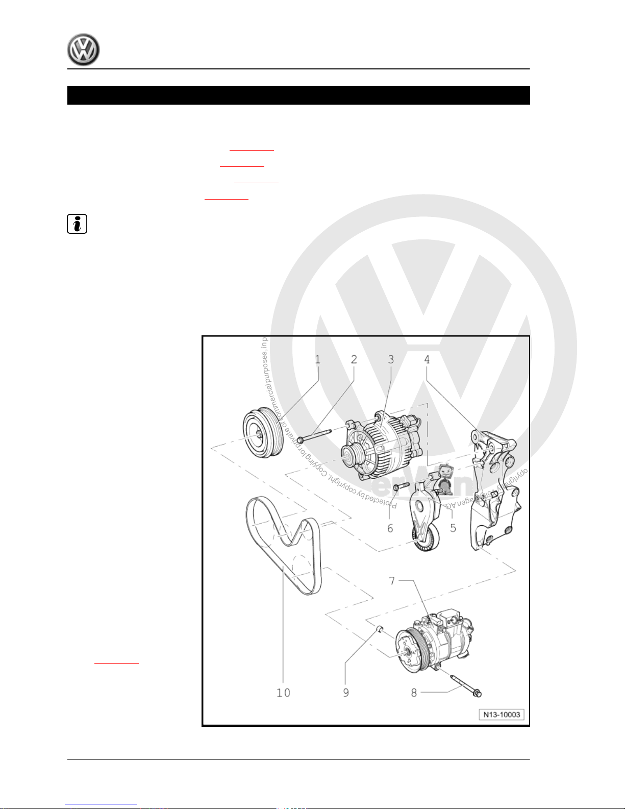
1.1 Assembly overview - poly V-belt drive
1 - Belt pulley and vibration
damper
❑ Can only be installed in
one position, holes are
offset.
2 - 25 Nm
3 - Alternator
4 - Bracket
❑ For alternator and air
conditioner compressor.
5 - Poly V-belt tensioning ele‐
ment
❑ Swing with ring spanner
to slacken poly V-belt.
6 - 25 Nm
7 - Air conditioner compressor
8 - 25 Nm
9 - Dowel sleeves
10 - Poly V-belt
❑ Mark direction of rota‐
tion before removing.
❑ Check for wear.
❑ Do not kink.
❑ Removing and installing
⇒ page 13 .
Golf 2004 ➤ , Golf Plus 2005 ➤
4-cylinder diesel engine (1.9 l engine) - Edition 01.2009
12 Rep. Gr.13 - Crankshaft group
P
r
o
t
e
c
t
e
d
b
y
c
o
p
y
r
i
g
h
t
.
C
o
p
y
i
n
g
f
o
r
p
r
i
v
a
t
e
o
r
c
o
m
m
e
r
c
i
a
l
p
u
r
p
o
s
e
s
,
i
n
p
a
r
t
o
r
i
n
w
h
o
l
e
,
i
s
n
o
t
p
e
r
m
i
t
t
e
d
u
n
l
e
s
s
a
u
t
h
o
r
i
s
e
d
b
y
V
o
l
k
s
w
a
g
e
n
A
G
.
V
o
l
k
s
w
a
g
e
n
A
G
d
o
e
s
n
o
t
g
u
a
r
a
n
t
e
e
o
r
a
c
c
e
p
t
a
n
y
l
i
a
b
i
l
i
t
y
w
i
t
h
r
e
s
p
e
c
t
t
o
t
h
e
c
o
r
r
e
c
t
n
e
s
s
o
f
i
n
f
o
r
m
a
t
i
o
n
i
n
t
h
i
s
d
o
c
u
m
e
n
t
.
C
o
p
y
r
i
g
h
t
b
y
V
o
l
k
s
w
a
g
e
n
A
G
.
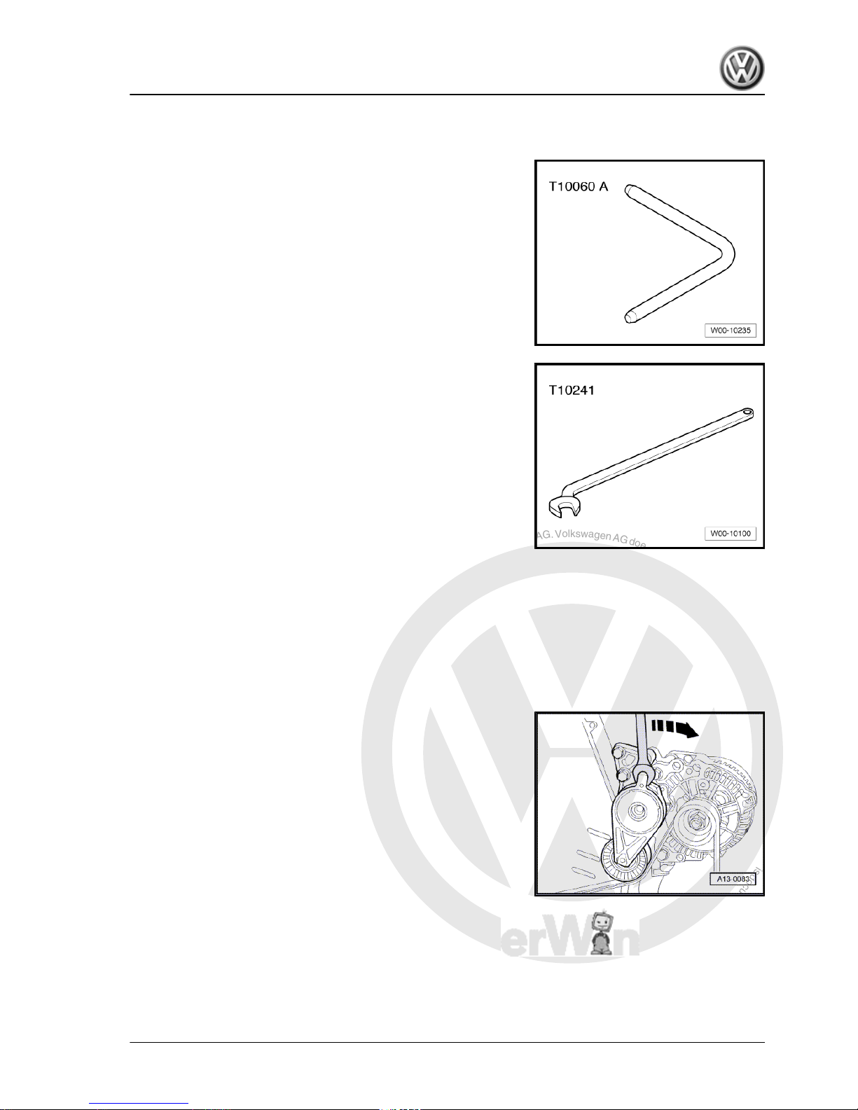
1.2 Removing and installing poly V-belt
Special tools and workshop equipment required
♦ Locking pin -T10060 A-
♦ 16 mm open-end spanner -T 10241-
1.2.1 Removing poly V-belt
– Remove insulation tray. ⇒ General body repairs, exterior;
Rep. Gr. 50 ; Body - front; Assembly overview .
– Pull fuel filter out of bracket and lay it with hoses to side.
– Mark direction of rotation of poly V-belt.
– Swing tensioning element in direction of arrow to remove ten‐
sion from poly V-belt.
The open-end spanner 16 mm -T 10241- is particularly well suited
to relieve tension.
Golf 2004 ➤ , Golf Plus 2005 ➤
4-cylinder diesel engine (1.9 l engine) - Edition 01.2009
1. Dismantling and assembling engine 13
P
r
o
t
e
c
t
e
d
b
y
c
o
p
y
r
i
g
h
t
.
C
o
p
y
i
n
g
f
o
r
p
r
i
v
a
t
e
o
r
c
o
m
m
e
r
c
i
a
l
p
u
r
p
o
s
e
s
,
i
n
p
a
r
t
o
r
i
n
w
h
o
l
e
,
i
s
n
o
t
p
e
r
m
i
t
t
e
d
u
n
l
e
s
s
a
u
t
h
o
r
i
s
e
d
b
y
V
o
l
k
s
w
a
g
e
n
A
G
.
V
o
l
k
s
w
a
g
e
n
A
G
d
o
e
s
n
o
t
g
u
a
r
a
n
t
e
e
o
r
a
c
c
e
p
t
a
n
y
l
i
a
b
i
l
i
t
y
w
i
t
h
r
e
s
p
e
c
t
t
o
t
h
e
c
o
r
r
e
c
t
n
e
s
s
o
f
i
n
f
o
r
m
a
t
i
o
n
i
n
t
h
i
s
d
o
c
u
m
e
n
t
.
C
o
p
y
r
i
g
h
t
b
y
V
o
l
k
s
w
a
g
e
n
A
G
.
– Lock tensioning element in position with locking pin -T10060
A- .
– Remove poly V-belt.
1.2.2 Installing poly V-belt
– Installation is carried out in the reverse sequence of removal.
Note
♦
Before installing poly V-belt, ensure that all ancillaries (alter‐
nator, air conditioner compressor) are secured tightly.
♦
When fitting poly V-belt, check direction of belt rotation and
ensure proper seating of belt in pulleys.
♦
Lastly, place poly V-belt over alternator.
After completing repairs always:
– Start engine and check belt running.
Belt drive without air conditioner compressor
Belt drive with air conditioner compressor
Golf 2004 ➤ , Golf Plus 2005 ➤
4-cylinder diesel engine (1.9 l engine) - Edition 01.2009
14 Rep. Gr.13 - Crankshaft group
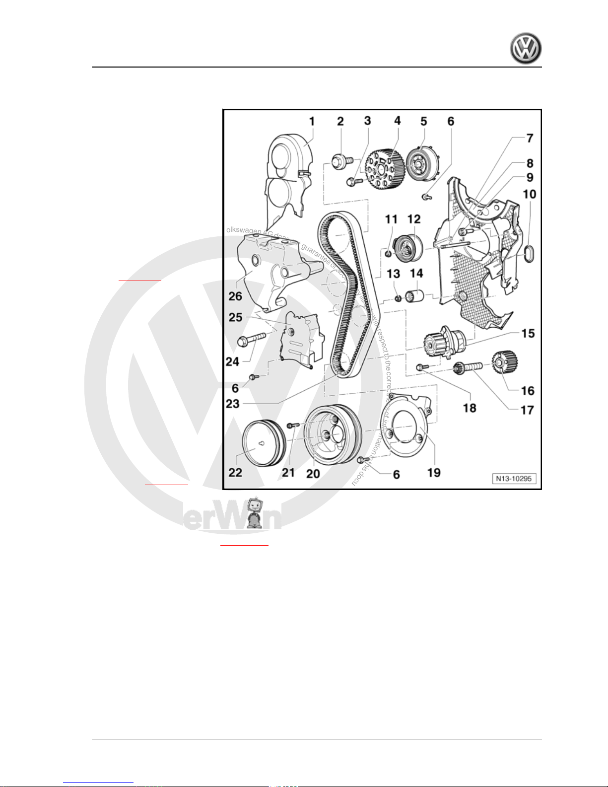
P
r
o
t
e
c
t
e
d
b
y
c
o
p
y
r
i
g
h
t
.
C
o
p
y
i
n
g
f
o
r
p
r
i
v
a
t
e
o
r
c
o
m
m
e
r
c
i
a
l
p
u
r
p
o
s
e
s
,
i
n
p
a
r
t
o
r
i
n
w
h
o
l
e
,
i
s
n
o
t
p
e
r
m
i
t
t
e
d
u
n
l
e
s
s
a
u
t
h
o
r
i
s
e
d
b
y
V
o
l
k
s
w
a
g
e
n
A
G
.
V
o
l
k
s
w
a
g
e
n
A
G
d
o
e
s
n
o
t
g
u
a
r
a
n
t
e
e
o
r
a
c
c
e
p
t
a
n
y
l
i
a
b
i
l
i
t
y
w
i
t
h
r
e
s
p
e
c
t
t
o
t
h
e
c
o
r
r
e
c
t
n
e
s
s
o
f
i
n
f
o
r
m
a
t
i
o
n
i
n
t
h
i
s
d
o
c
u
m
e
n
t
.
C
o
p
y
r
i
g
h
t
b
y
V
o
l
k
s
w
a
g
e
n
A
G
.
1.3 Assembly overview - toothed belt drive
1 - Toothed belt guard upper
part
2 - 100 Nm
3 - 25 Nm
4 - Camshaft pulley
5 - Hub
❑ With sender wheel
❑ Use counterhold tool -
T10051- to loosen and
tighten.
❑ To remove, use puller -
T10052-
❑ Removing and installing
⇒ page 80 , removing
and installing camshaft.
6 - 10 Nm
❑ Renew
7 - Stud
❑ 15 Nm
8 - Rear toothed belt guard
9 - 25 Nm
10 - Sealing grommet
❑ Renew if damaged.
11 - 20 Nm + 1/8 turn (45°) fur‐
ther
12 - Tensioning roller
❑ Remove engine support
in order to remove and
install ⇒ page 16 .
13 - 20 Nm
14 - Idler roller
15 - Coolant pump
❑ Removing and installing ⇒ page 106 .
16 - Crankshaft toothed belt pulley
17 - 120 Nm + 1/4 turn (90°) further
❑ Renew
❑ Use counterhold tool -3099- to loosen and tighten.
❑ Do not additionally oil or grease thread and shoulder.
❑ Turning further can be done in several stages.
18 - 15 Nm
19 - Toothed belt guard lower part
20 - Belt pulley and vibration damper
❑ Can only be installed in one position, holes are offset.
21 - 10 Nm + 1/4 turn (90°) further
❑ Renew
Golf 2004 ➤ , Golf Plus 2005 ➤
4-cylinder diesel engine (1.9 l engine) - Edition 01.2009
1. Dismantling and assembling engine 15
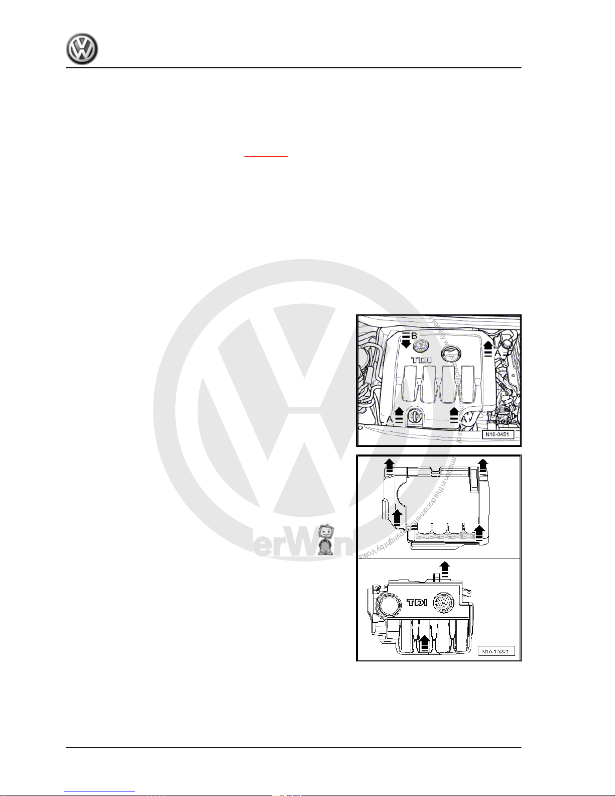
P
r
o
t
e
c
t
e
d
b
y
c
o
p
y
r
i
g
h
t
.
C
o
p
y
i
n
g
f
o
r
p
r
i
v
a
t
e
o
r
c
o
m
m
e
r
c
i
a
l
p
u
r
p
o
s
e
s
,
i
n
p
a
r
t
o
r
i
n
w
h
o
l
e
,
i
s
n
o
t
p
e
r
m
i
t
t
e
d
u
n
l
e
s
s
a
u
t
h
o
r
i
s
e
d
b
y
V
o
l
k
s
w
a
g
e
n
A
G
.
V
o
l
k
s
w
a
g
e
n
A
G
d
o
e
s
n
o
t
g
u
a
r
a
n
t
e
e
o
r
a
c
c
e
p
t
a
n
y
l
i
a
b
i
l
i
t
y
w
i
t
h
r
e
s
p
e
c
t
t
o
t
h
e
c
o
r
r
e
c
t
n
e
s
s
o
f
i
n
f
o
r
m
a
t
i
o
n
i
n
t
h
i
s
d
o
c
u
m
e
n
t
.
C
o
p
y
r
i
g
h
t
b
y
V
o
l
k
s
w
a
g
e
n
A
G
.
22 - Cover
23 - Toothed belt
❑ Mark direction of rotation before removing.
❑ Check for wear.
❑ Do not kink.
❑ Removing, installing and tensioning ⇒ page 50 .
24 - 40 Nm + 1/2 turn (180°) further
❑ Renew
25 - Toothed belt guard centre part
26 - Engine bracket
1.3.1 Removing and installing engine support
Special tools and workshop equipment required
♦ Support bracket -10 - 222 A-
♦ Torque wrench -V.A.G 1331-
– Remove engine cover.
– To do this, pull engine cover upwards abruptly at front and right
-arrows A- and then pull forwards out of rear fastening
-arrow B-.
Two-piece engine cover
For two-piece engine cover, first pull outer engine cover abruptly
upwards at -arrows-, then pull inner engine cover abruptly up‐
wards at -arrows-.
Golf 2004 ➤ , Golf Plus 2005 ➤
4-cylinder diesel engine (1.9 l engine) - Edition 01.2009
16 Rep. Gr.13 - Crankshaft group
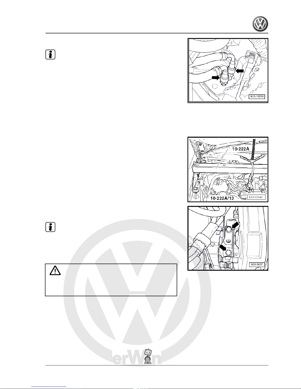
P
r
o
t
e
c
t
e
d
b
y
c
o
p
y
r
i
g
h
t
.
C
o
p
y
i
n
g
f
o
r
p
r
i
v
a
t
e
o
r
c
o
m
m
e
r
c
i
a
l
p
u
r
p
o
s
e
s
,
i
n
p
a
r
t
o
r
i
n
w
h
o
l
e
,
i
s
n
o
t
p
e
r
m
i
t
t
e
d
u
n
l
e
s
s
a
u
t
h
o
r
i
s
e
d
b
y
V
o
l
k
s
w
a
g
e
n
A
G
.
V
o
l
k
s
w
a
g
e
n
A
G
d
o
e
s
n
o
t
g
u
a
r
a
n
t
e
e
o
r
a
c
c
e
p
t
a
n
y
l
i
a
b
i
l
i
t
y
w
i
t
h
r
e
s
p
e
c
t
t
o
t
h
e
c
o
r
r
e
c
t
n
e
s
s
o
f
i
n
f
o
r
m
a
t
i
o
n
i
n
t
h
i
s
d
o
c
u
m
e
n
t
.
C
o
p
y
r
i
g
h
t
b
y
V
o
l
k
s
w
a
g
e
n
A
G
.
– Separate push-on connectors of fuel lines -arrows-.
Note
♦
Do this by pressing in catch of push-on connectors.
♦
Ensure that no fuel escapes (use a cloth).
– Lay fuel filter with hoses to side.
– Disconnect coolant hose from top of expansion tank.
– Remove expansion tank and lay it to side.
– Remove charge air pipe between charge air cooler and turbo‐
charger.
– Carefully cover or seal open ends.
Golf, Golf Plus and Touran:
– Fit engine support bracket -10-222A- with adapters -10-222A/
13- and take up weight of engine in installation position.
– Remove securing bolts from assembly mounting/engine sup‐
port -arrows- and remove complete assembly mounting.
Note
♦
The assembly mounting may only be removed if the engine is
supported with support bracket 10-222A!
♦
The engine support must only be loosened when the assembly
mounting has been removed.
WARNING
When raising and lowering engine using support bracket
-10-222A- , ensure that no components or hoses are damaged
or torn off.
– Remove noise insulation tray ⇒ General body repairs, exteri‐
or; Rep. Gr. 50 ; Body - front; Assembly overview - noise
insulation .
– Remove front right wheel housing liner.
Golf 2004 ➤ , Golf Plus 2005 ➤
4-cylinder diesel engine (1.9 l engine) - Edition 01.2009
1. Dismantling and assembling engine 17
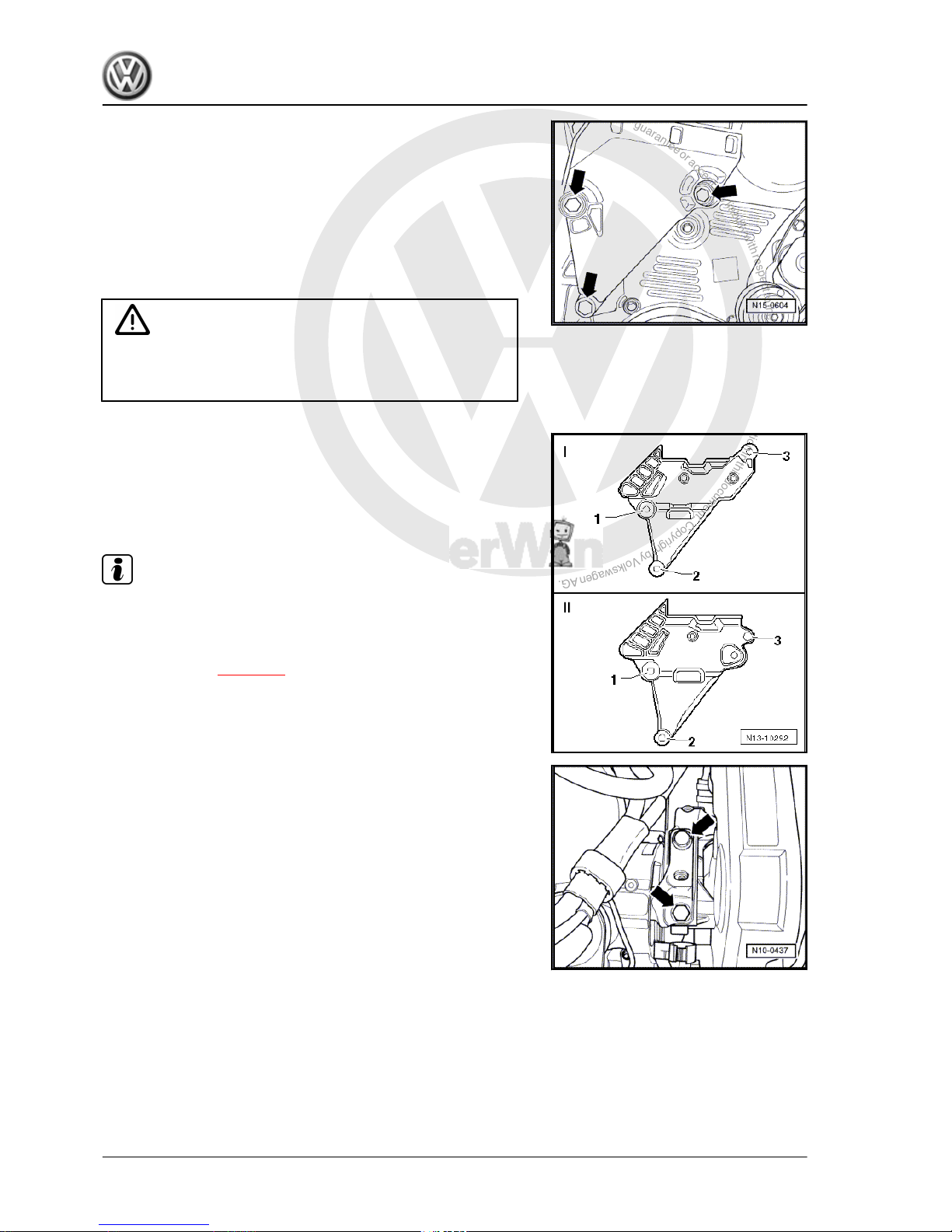
P
r
o
t
e
c
t
e
d
b
y
c
o
p
y
r
i
g
h
t
.
C
o
p
y
i
n
g
f
o
r
p
r
i
v
a
t
e
o
r
c
o
m
m
e
r
c
i
a
l
p
u
r
p
o
s
e
s
,
i
n
p
a
r
t
o
r
i
n
w
h
o
l
e
,
i
s
n
o
t
p
e
r
m
i
t
t
e
d
u
n
l
e
s
s
a
u
t
h
o
r
i
s
e
d
b
y
V
o
l
k
s
w
a
g
e
n
A
G
.
V
o
l
k
s
w
a
g
e
n
A
G
d
o
e
s
n
o
t
g
u
a
r
a
n
t
e
e
o
r
a
c
c
e
p
t
a
n
y
l
i
a
b
i
l
i
t
y
w
i
t
h
r
e
s
p
e
c
t
t
o
t
h
e
c
o
r
r
e
c
t
n
e
s
s
o
f
i
n
f
o
r
m
a
t
i
o
n
i
n
t
h
i
s
d
o
c
u
m
e
n
t
.
C
o
p
y
r
i
g
h
t
b
y
V
o
l
k
s
w
a
g
e
n
A
G
.
– Raise engine with support bracket -10-222A- until both upper
bolts of engine support can be loosened and removed.
– Lower engine with support bracket -10-222A- until lower bolt
can be loosened and removed.
– Remove engine support upwards.
Installing
– Position engine support from above on cylinder block.
– Insert new bolts and tighten hand-tight.
Caution
The tightening sequence and specified torques for the engine
support securing bolts must always be followed. Otherwise the
engine support can be stressed and it can break.
– Tighten bolts for engine support in the sequence shown
-1…3- to 40 Nm + 1/2 turn (180 °) further. To do this, raise or
lower engine using support bracket -10 - 222 A- .
I : Engine support with less clearance to engine
II: Engine support with greater clearance to engine
Note
Before installing assembly mounting, tighten all engine support
bolts to prescribed torque.
– Install assembly mounting between engine and body, renew
securing bolts ⇒ page 10 .
– Bolt engine assembly mounting to engine support -arrows- by
bringing contact surfaces together using support bracket
-10-222A- . Specified torque: 60 Nm + 90° (1/4 turn) further.
Further assembly is basically the reverse of the dismantling se‐
quence. In the process, note the following:
♦ Ensure that fuel hose connections are tight.
♦ Do not interchange supply line and return line (return line blue
or with blue marking, supply line black).
♦ When installing charge air pipes, ensure that locking lugs en‐
gage correctly.
– Install wheel housing liner.
– Install noise insulation tray ⇒ General body repairs, exterior;
Rep. Gr. 50 ; Body - front; Assembly overview - noise insula‐
tion
Golf 2004 ➤ , Golf Plus 2005 ➤
4-cylinder diesel engine (1.9 l engine) - Edition 01.2009
18 Rep. Gr.13 - Crankshaft group
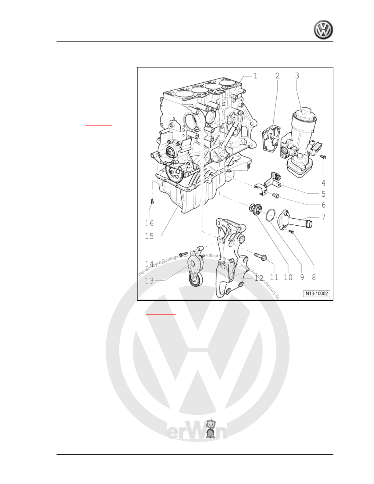
P
r
o
t
e
c
t
e
d
b
y
c
o
p
y
r
i
g
h
t
.
C
o
p
y
i
n
g
f
o
r
p
r
i
v
a
t
e
o
r
c
o
m
m
e
r
c
i
a
l
p
u
r
p
o
s
e
s
,
i
n
p
a
r
t
o
r
i
n
w
h
o
l
e
,
i
s
n
o
t
p
e
r
m
i
t
t
e
d
u
n
l
e
s
s
a
u
t
h
o
r
i
s
e
d
b
y
V
o
l
k
s
w
a
g
e
n
A
G
.
V
o
l
k
s
w
a
g
e
n
A
G
d
o
e
s
n
o
t
g
u
a
r
a
n
t
e
e
o
r
a
c
c
e
p
t
a
n
y
l
i
a
b
i
l
i
t
y
w
i
t
h
r
e
s
p
e
c
t
t
o
t
h
e
c
o
r
r
e
c
t
n
e
s
s
o
f
i
n
f
o
r
m
a
t
i
o
n
i
n
t
h
i
s
d
o
c
u
m
e
n
t
.
C
o
p
y
r
i
g
h
t
b
y
V
o
l
k
s
w
a
g
e
n
A
G
.
1.4 Assembly overview - crankcase
1 - Cylinder block
❑ Removing and installing
sealing flange and fly‐
wheel ⇒ page 20 .
❑ Removing and installing
crankshaft ⇒ page 33
❑ Dismantling and assem‐
bling pistons and con‐
rods ⇒ page 33
2 - Gasket
❑ Renew
3 - Oil filter bracket
❑ Dismantling and assem‐
bling ⇒ page 92 .
4 - 15 Nm + 1/4 turn (90°) fur‐
ther
❑ Renew
❑ First fit upper left and
lower right bolts and
then tighten all four bolts
diagonally.
5 - Bracket
6 - 20 Nm
7 - Connection
❑ For thermostat.
8 - 15 Nm
9 - O-ring
❑ Renew
10 - Thermostat
❑ Removing and installing
⇒ page 108 .
❑ Observe installation position ⇒ page 108 , removing and installing thermostat.
❑ Check: Heat thermostat in water
❑ Opening begins at approx. 85 °C
❑ Ends at approx. 105 °C
❑ Opening lift at least 7 mm.
11 - Hexagon bolt
❑ Tightening sequence and torque specifications ⇒ Heating, air conditioning; Rep. Gr. 87 ; Removing and
installing compressor bracket .
12 - Bracket
❑ For alternator, if air conditioner compressor is fitted
13 - Poly V-belt tensioning element
14 - 25 Nm
15 - Sump
❑ Clean sealing surface before fitting.
❑ Install with silicone sealant -D 176 404 A2- .
16 - 15 Nm
Golf 2004 ➤ , Golf Plus 2005 ➤
4-cylinder diesel engine (1.9 l engine) - Edition 01.2009
1. Dismantling and assembling engine 19
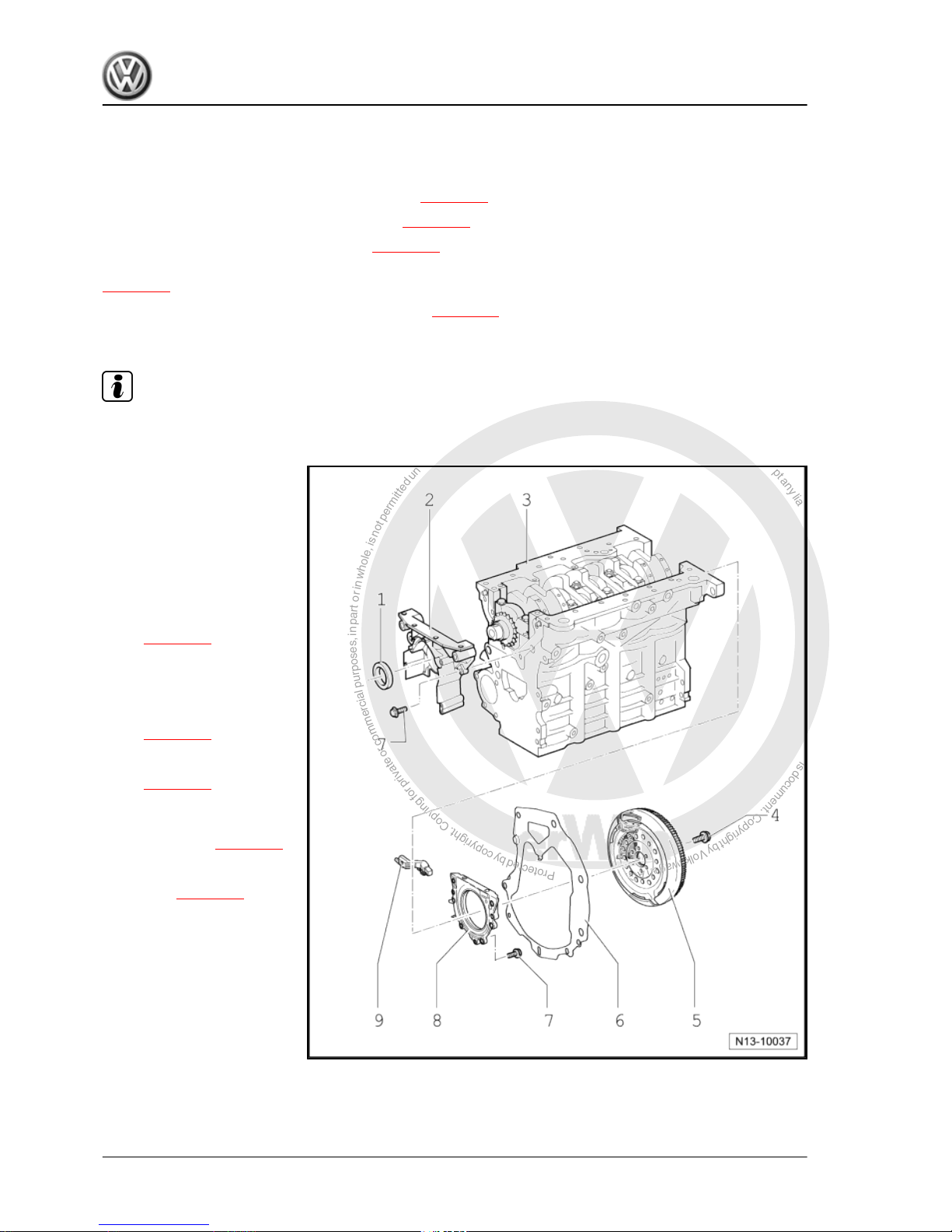
P
r
o
t
e
c
t
e
d
b
y
c
o
p
y
r
i
g
h
t
.
C
o
p
y
i
n
g
f
o
r
p
r
i
v
a
t
e
o
r
c
o
m
m
e
r
c
i
a
l
p
u
r
p
o
s
e
s
,
i
n
p
a
r
t
o
r
i
n
w
h
o
l
e
,
i
s
n
o
t
p
e
r
m
i
t
t
e
d
u
n
l
e
s
s
a
u
t
h
o
r
i
s
e
d
b
y
V
o
l
k
s
w
a
g
e
n
A
G
.
V
o
l
k
s
w
a
g
e
n
A
G
d
o
e
s
n
o
t
g
u
a
r
a
n
t
e
e
o
r
a
c
c
e
p
t
a
n
y
l
i
a
b
i
l
i
t
y
w
i
t
h
r
e
s
p
e
c
t
t
o
t
h
e
c
o
r
r
e
c
t
n
e
s
s
o
f
i
n
f
o
r
m
a
t
i
o
n
i
n
t
h
i
s
d
o
c
u
m
e
n
t
.
C
o
p
y
r
i
g
h
t
b
y
V
o
l
k
s
w
a
g
e
n
A
G
.
2 Removing and installing sealing
flange and flywheel
Assembly overview - sealing flange and flywheel ⇒ page 20
Removing and installing engine speed sender ⇒ page 31
Renewing crankshaft oil seal - pulley end ⇒ page 21 .
Removing and installing sealing flange - pulley end
⇒ page 21 .
Renewing crankshaft sealing flange - flywheel end ⇒ page 25 .
2.1 Assembly overview - sealing flanges and flywheel
Note
Repairing clutch ⇒ 6-speed manual gearbox 02S; Rep. Gr. 30 ; Repairing clutch.
1 - Seal
❑ Do not additionally oil or
grease the oil seal seal‐
ing lip.
❑ Before installing, re‐
move oil residue from
crankshaft journal using
a clean cloth.
❑ Renewing crankshaft oil
seal - pulley end
⇒ page 21 .
2 - Sealing flange
❑ Must be positioned on
dowel sleeves.
❑ Removing and installing
⇒ page 23 .
❑ Install with silicone seal‐
ant -D 176 404 A2-
⇒ page 23 .
3 - Cylinder block
❑ Removing and installing
crankshaft ⇒ page 33
❑ Dismantling and assem‐
bling pistons and con‐
rods ⇒ page 33
4 - 60 Nm + 1/4 turn (90°) fur‐
ther
❑ Renew
5 - Flywheel
❑ To remove and install
flywheel, counterhold
with 3067.
6 - Intermediate plate
❑ Must be positioned on dowel sleeves.
❑ Do not damage or bend when assembling.
Golf 2004 ➤ , Golf Plus 2005 ➤
4-cylinder diesel engine (1.9 l engine) - Edition 01.2009
20 Rep. Gr.13 - Crankshaft group
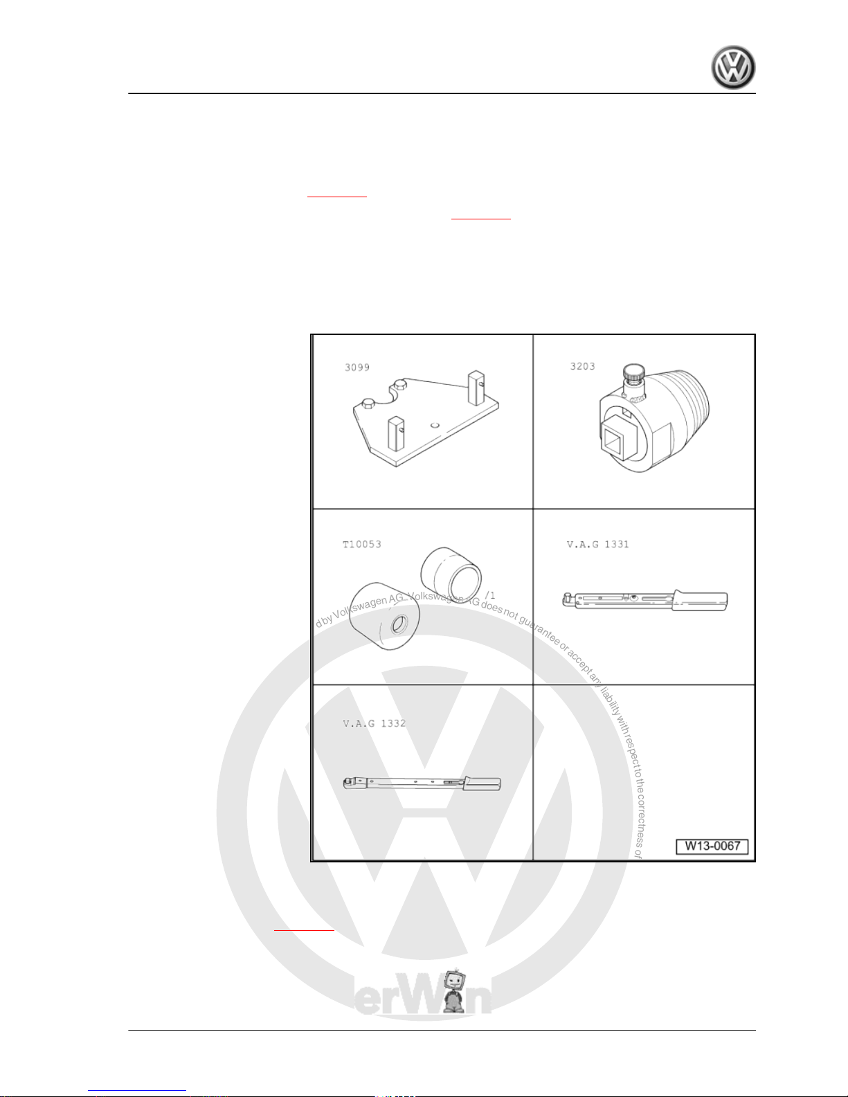
P
r
o
t
e
c
t
e
d
b
y
c
o
p
y
r
i
g
h
t
.
C
o
p
y
i
n
g
f
o
r
p
r
i
v
a
t
e
o
r
c
o
m
m
e
r
c
i
a
l
p
u
r
p
o
s
e
s
,
i
n
p
a
r
t
o
r
i
n
w
h
o
l
e
,
i
s
n
o
t
p
e
r
m
i
t
t
e
d
u
n
l
e
s
s
a
u
t
h
o
r
i
s
e
d
b
y
V
o
l
k
s
w
a
g
e
n
A
G
.
V
o
l
k
s
w
a
g
e
n
A
G
d
o
e
s
n
o
t
g
u
a
r
a
n
t
e
e
o
r
a
c
c
e
p
t
a
n
y
l
i
a
b
i
l
i
t
y
w
i
t
h
r
e
s
p
e
c
t
t
o
t
h
e
c
o
r
r
e
c
t
n
e
s
s
o
f
i
n
f
o
r
m
a
t
i
o
n
i
n
t
h
i
s
d
o
c
u
m
e
n
t
.
C
o
p
y
r
i
g
h
t
b
y
V
o
l
k
s
w
a
g
e
n
A
G
.
7 - 15 Nm
❑ Renew
8 - Sealing flange with oil seal
❑ Renew complete with oil seal and sender wheel only.
❑ Removing and installing ⇒ page 25 .
9 - Removing and installing engine speed sender -G28- ⇒ page 31 .,
❑ Loosen and tighten using commercially available ball-ended hexagon key socket
❑ Specified torque: 5 Nm.
2.2 Renewing crankshaft oil seal - pulley end
Special tools and workshop
equipment required
♦ Counterhold tool -3099-
♦ Oil seal extractor -3203-
♦ Assembly tool -T10053-
♦ Torque wrench -
V.A.G 1331-
♦ Torque wrench -
V.A.G 1332-
2.2.1 Removing
– Remove toothed belt. ⇒ page 50
Golf 2004 ➤ , Golf Plus 2005 ➤
4-cylinder diesel engine (1.9 l engine) - Edition 01.2009
2. Removing and installing sealing flange and flywheel 21
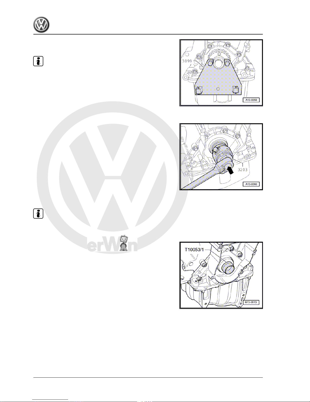
P
r
o
t
e
c
t
e
d
b
y
c
o
p
y
r
i
g
h
t
.
C
o
p
y
i
n
g
f
o
r
p
r
i
v
a
t
e
o
r
c
o
m
m
e
r
c
i
a
l
p
u
r
p
o
s
e
s
,
i
n
p
a
r
t
o
r
i
n
w
h
o
l
e
,
i
s
n
o
t
p
e
r
m
i
t
t
e
d
u
n
l
e
s
s
a
u
t
h
o
r
i
s
e
d
b
y
V
o
l
k
s
w
a
g
e
n
A
G
.
V
o
l
k
s
w
a
g
e
n
A
G
d
o
e
s
n
o
t
g
u
a
r
a
n
t
e
e
o
r
a
c
c
e
p
t
a
n
y
l
i
a
b
i
l
i
t
y
w
i
t
h
r
e
s
p
e
c
t
t
o
t
h
e
c
o
r
r
e
c
t
n
e
s
s
o
f
i
n
f
o
r
m
a
t
i
o
n
i
n
t
h
i
s
d
o
c
u
m
e
n
t
.
C
o
p
y
r
i
g
h
t
b
y
V
o
l
k
s
w
a
g
e
n
A
G
.
– Remove crankshaft toothed belt pulley. To do this, lock tooth‐
ed belt pulley using counterhold tool -3099- .
Note
When bolting on counterhold tool, place two washers between
toothed belt pulley and counterhold tool.
– To guide oil seal extractor -3203- , screw central bolt by hand
into crankshaft to stop.
– Unscrew inner part of oil seal extractor two turns (approx. 3
mm) out of outer part and lock with knurled screw.
– Oil threaded head of oil seal extractor.
– Using great pressure, screw oil seal extractor as far as possi‐
ble into seal.
– Loosen knurled screw and turn inner part against crankshaft
until oil seal is pulled out.
2.2.2 Installing
Note
The oil seal sealing lip must not be additionally oiled or greased.
– Remove oil residue from crankshaft journal using clean cloth.
– Place guide sleeve -T10053/1- onto crankshaft journal.
– Slide oil seal over guide sleeve onto crankshaft journal.
Golf 2004 ➤ , Golf Plus 2005 ➤
4-cylinder diesel engine (1.9 l engine) - Edition 01.2009
22 Rep. Gr.13 - Crankshaft group
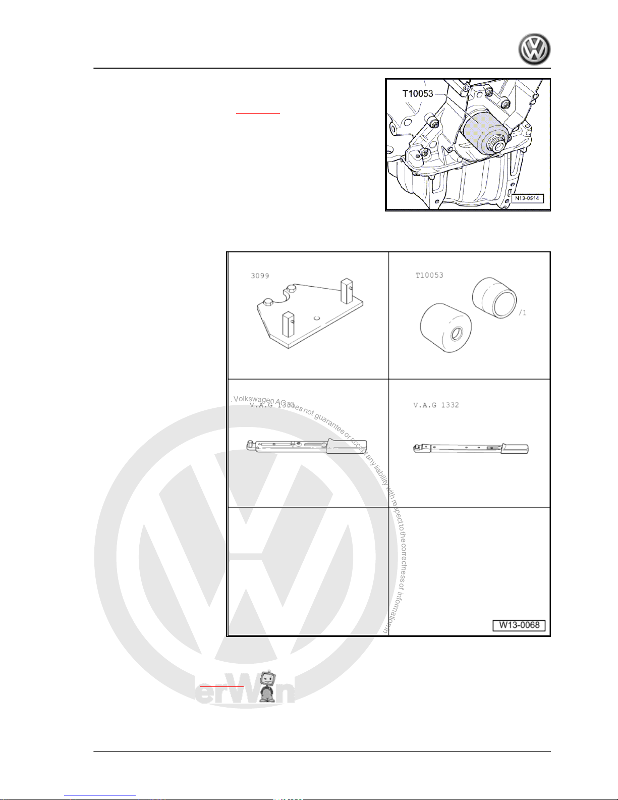
P
r
o
t
e
c
t
e
d
b
y
c
o
p
y
r
i
g
h
t
.
C
o
p
y
i
n
g
f
o
r
p
r
i
v
a
t
e
o
r
c
o
m
m
e
r
c
i
a
l
p
u
r
p
o
s
e
s
,
i
n
p
a
r
t
o
r
i
n
w
h
o
l
e
,
i
s
n
o
t
p
e
r
m
i
t
t
e
d
u
n
l
e
s
s
a
u
t
h
o
r
i
s
e
d
b
y
V
o
l
k
s
w
a
g
e
n
A
G
.
V
o
l
k
s
w
a
g
e
n
A
G
d
o
e
s
n
o
t
g
u
a
r
a
n
t
e
e
o
r
a
c
c
e
p
t
a
n
y
l
i
a
b
i
l
i
t
y
w
i
t
h
r
e
s
p
e
c
t
t
o
t
h
e
c
o
r
r
e
c
t
n
e
s
s
o
f
i
n
f
o
r
m
a
t
i
o
n
i
n
t
h
i
s
d
o
c
u
m
e
n
t
.
C
o
p
y
r
i
g
h
t
b
y
V
o
l
k
s
w
a
g
e
n
A
G
.
– Press oil seal in to stop using assembly tool -T10053- and
centre bolt.
– Install and tighten toothed belt ⇒ page 50 .
2.3 Removing and installing sealing flange - pulley end
Special tools and workshop
equipment required
♦ Counterhold tool -3099-
♦ Assembly tool -T10053-
♦ Torque wrench -
V.A.G 1331-
♦ Torque wrench -
V.A.G 1332-
♦ Hand drill with plastic brush
attachment
♦ Silicone sealant -D 176 404
A-
♦ Flat scraper
2.3.1 Removing
– Remove toothed belt. ⇒ page 50
Golf 2004 ➤ , Golf Plus 2005 ➤
4-cylinder diesel engine (1.9 l engine) - Edition 01.2009
2. Removing and installing sealing flange and flywheel 23
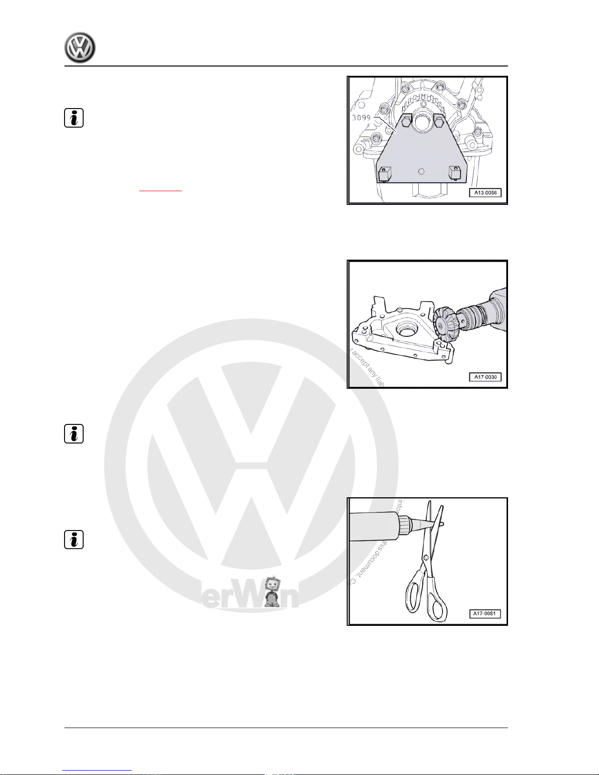
P
r
o
t
e
c
t
e
d
b
y
c
o
p
y
r
i
g
h
t
.
C
o
p
y
i
n
g
f
o
r
p
r
i
v
a
t
e
o
r
c
o
m
m
e
r
c
i
a
l
p
u
r
p
o
s
e
s
,
i
n
p
a
r
t
o
r
i
n
w
h
o
l
e
,
i
s
n
o
t
p
e
r
m
i
t
t
e
d
u
n
l
e
s
s
a
u
t
h
o
r
i
s
e
d
b
y
V
o
l
k
s
w
a
g
e
n
A
G
.
V
o
l
k
s
w
a
g
e
n
A
G
d
o
e
s
n
o
t
g
u
a
r
a
n
t
e
e
o
r
a
c
c
e
p
t
a
n
y
l
i
a
b
i
l
i
t
y
w
i
t
h
r
e
s
p
e
c
t
t
o
t
h
e
c
o
r
r
e
c
t
n
e
s
s
o
f
i
n
f
o
r
m
a
t
i
o
n
i
n
t
h
i
s
d
o
c
u
m
e
n
t
.
C
o
p
y
r
i
g
h
t
b
y
V
o
l
k
s
w
a
g
e
n
A
G
.
– Remove crankshaft toothed belt pulley. To do this, lock tooth‐
ed belt pulley using counterhold tool -3099- .
Note
When bolting on counterhold tool, place two washers between
toothed belt pulley and counterhold tool.
– Drain engine oil.
– Remove sump ⇒ page 88 .
– Pull off front sealing flange.
– Remove sealing flange; if necessary, loosen by applying light
blows with a rubber-headed hammer.
– Remove sealant residue from cylinder block with a flat scraper.
– Remove residual sealant from sealing flange using a plastic
rotary brush (wear eye protection).
– Clean sealing surfaces. They must be free of oil and grease.
2.3.2 Installing
Note
♦
Observe expiry date of sealing compound.
♦
Install sealing flange within 5 minutes of applying the silicone
sealant.
– Cut off tube nozzle at forward marking (approx. 3 mm nozzle
∅).
Note
♦
Sealant bead must not be wider than 2...3 mm, because oth‐
erwise excess sealant can enter sump and clog strainer in oil
pump suction pipe as well as drip onto crankshaft oil seal.
♦
Before applying sealant bead, cover sealing surface of oil seal
with a clean cloth.
Golf 2004 ➤ , Golf Plus 2005 ➤
4-cylinder diesel engine (1.9 l engine) - Edition 01.2009
24 Rep. Gr.13 - Crankshaft group
 Loading...