


Volkswagen 01M User Manual

AUTO TRANS DIAGNOSIS - 01M
Article Text
1996 Volkswagen Golf
For Volkswagen Technical Site
Copyright © 1998 Mitchell Repair Information Company, LLC
ARTICLE BEGINNING
AUTOMATIC TRANSMISSIONS
Volkswagen Type 01M
Cabrio, Golf, Golf III, GTI Jetta, Jetta III, Passat
APPLICATION & LABOR TIMES
APPLICATION & LABOR TIMES
ДДДДДДДДДДДДДДДДДДДДДДДДДДДДДДДДДДДДДДДДДДДДДДДДДДДДДДДДДДДД
Vehicle Labor Times Trans.
Application (1) R & I (2) Overhaul Model
1995-96
Cabrio ............... 4.4 ......... 6.3 .... 01M (CLK)
Golf, GTI & Jetta
4-Cylinder
Gas ................. 4.4 ......... 6.3 .... 01M (CLK)
Turbo Diesel ........ 4.4 ......... 6.3 .... 01M (CKZ)
V6 ................... 4.4 ......... 6.3 .... 01M (CLB)
Passat
4-Cylinder
Gas ................. 4.9 ......... 6.3 .... 01M (CLK)
Turbo Diesel ........ 4.9 ......... 6.3 .... 01M (CKZ)
V6 ................... 4.9 ......... 6.3 .... 01M (CLB)
Thursday, August 19, 1999 11:28PM
(1) - Removal and installation of transmission from vehicle
chassis.
(2) - On bench overhaul for transmission and differential.
DOES NOT include removal and installation.
ДДДДДДДДДДДДДДДДДДДДДДДДДДДДДДДДДДДДДДДДДДДДДДДДДДДДДДДДДДДД
IDENTIFICATION
Volkswagen Audi Group (VAG) transaxle type is cast into top
of transaxle case, next to ATF cooler. Transaxle code and build date
are located on top of transaxle case, next to starter.
DESCRIPTION & OPERATION
Transaxle includes a 4-speed automatic transmission, lock-up
torque converter, final drive and solenoid-operated valve body. See
Fig. 1. Under normal conditions, all shifts are controlled by a
Transaxle Control Module (TCM). See Fig. 2. Fourth gear is an
overdrive gear.
AUTO TRANS DIAGNOSIS - 01M
Article Text (p. 2)
1996 Volkswagen Golf
For Volkswagen Technical Site
Copyright © 1998 Mitchell Repair Information Company, LLC
Thursday, August 19, 1999 11:28PM
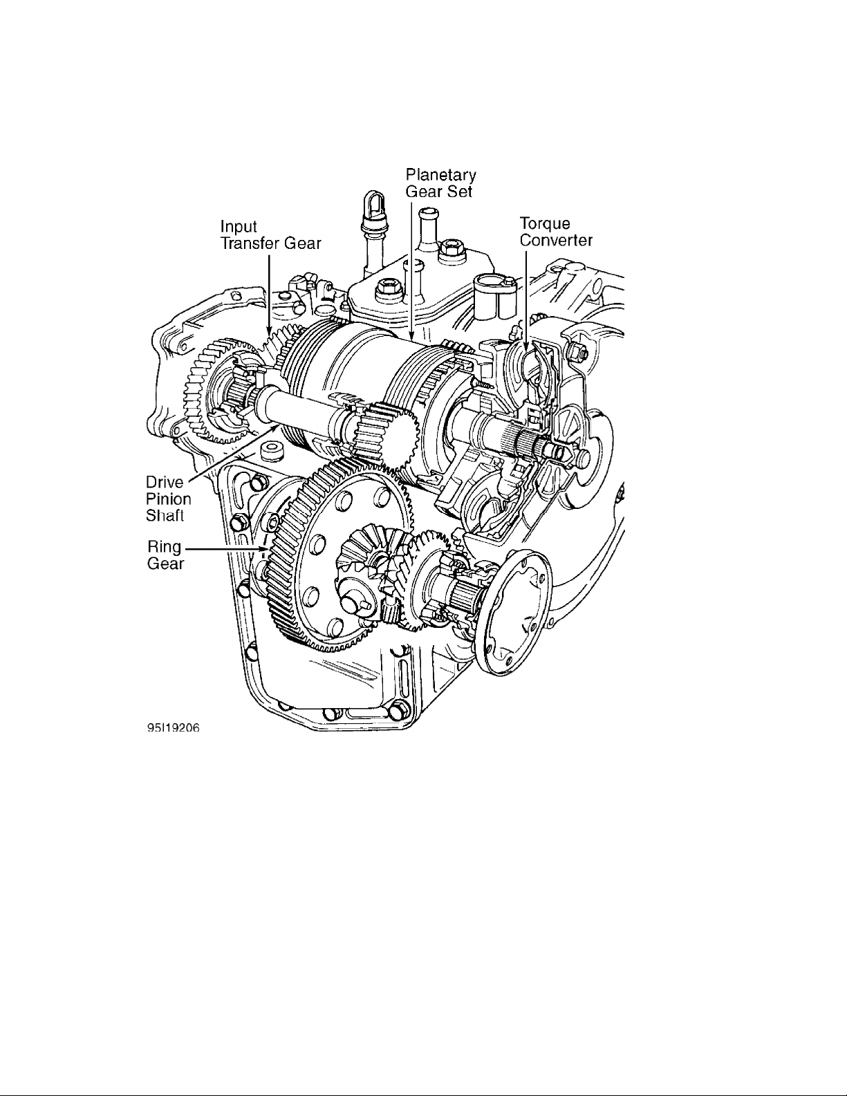
Fig. 1: Cross-Sectional View Of Transaxle Components
Courtesy of Volkswagen United States, Inc.

AUTO TRANS DIAGNOSIS - 01M
Article Text (p. 3)
1996 Volkswagen Golf
For Volkswagen Technical Site
Copyright © 1998 Mitchell Repair Information Company, LLC
Thursday, August 19, 1999 11:28PM
Fig. 2: Identifying TCM & Shift Lock Electrical Components
Courtesy of Volkswagen United States, Inc.
The transmission elements consist of a planetary gear set,
one-way roller clutch, 3 apply clutches, 2 brake clutches and a torque
converter lock-up clutch. See Figs. 1 and 3.
All 4 forward gears are hydraulically activated. When the
lock-up clutch is engaged, the forward gears become mechanically
driven by eliminating torque converter slip. The lock-up clutch is

AUTO TRANS DIAGNOSIS - 01M
Article Text (p. 4)
1996 Volkswagen Golf
For Volkswagen Technical Site
Copyright © 1998 Mitchell Repair Information Company, LLC
engaged depending on engine load and vehicle speed.
Power from the transmission is connected to the drive pinion
through transfer gears. A ring gear and differential assembly are
connected to flanges which spin the drive axles.
The electronic control consists of a TCM (located under rear
seat), control solenoids, various sensors and switches. The control
solenoids direct oil pressure inside the valve body. Solenoid valves
No. 1-4 control the apply and brake clutches. Solenoid valves No. 5
and 7 control shift smoothness. Solenoid valve No. 6 is a frequency
valve and controls the main hydraulic pressure. The TCM controls the
main hydraulic pressure by varying the duty cycle.
The TCM monitors input and output signals. If electrical
problems occur, TCM will record faults in TCM memory and may go into
fail-safe mode (also known as emergency running mode). If TCM enters
fail-safe mode, the transaxle will operate manually in reverse, 1st or
3rd gear. In fail-safe mode, 3rd gear operates with gear selector in
2nd, 3rd or "D". If engine is started with TCM in fail-safe mode, TCM
activates 3rd gear hydraulically. The TCM memory can only be read
using Scan Tool (VAG 1551) and Adapter (VAG 1551/3).
The TCM also controls shift lock system. This system locks
the gear selector in Park or Neutral position unless the brake pedal
is pressed. The TCM uses a shift lock control relay to release a gearselector mounted solenoid. See Fig. 2.
Thursday, August 19, 1999 11:28PM
Fig. 3: View Of Transaxle Clutch Elements
Courtesy of Volkswagen United States, Inc.

AUTO TRANS DIAGNOSIS - 01M
Article Text (p. 5)
1996 Volkswagen Golf
For Volkswagen Technical Site
Copyright © 1998 Mitchell Repair Information Company, LLC
LUBRICATION & ADJUSTMENTS
NOTE: See appropriate AUTOMATIC TRANSMISSION SERVICING article in
TRANSMISSION SERVICING section.
TROUBLE SHOOTING
SYMPTOM DIAGNOSIS
Leak At Torque Converter
Check drive plate clearance, torque converter bushing, oil
seal or oil pump assembly. Repair as necessary.
Transaxle Fluid In Coolant
Faulty transaxle oil cooler. Replace transaxle oil cooler and
friction plates in transaxle. Clean transaxle.
Thursday, August 19, 1999 11:28PM
Transaxle & Differential Oils Mixed
Replace "O" ring and drive pinion seal on inner bearing
support.
Gear Selector Hard To Move
Check gear selector between shifter and transaxle. Repair as
necessary. Check parking lock assembly inside transaxle. Repair as
necessary.
No Drive In 1st Gear
Check for faulty 1st-3rd apply clutch or reverse brake
clutch.
No Drive In "D", "2" Or "3"
Check for faulty 1st-3rd apply clutch or one-way clutch.
No 2nd Gear In "D", "2" Or "3"
Check for faulty 2nd-4th brake clutch.
No 3rd Gear In "D" Or "3"
Check for faulty reverse apply clutch.
No 4th Gear In "D"
Check for faulty 2nd-4th brake clutch.
No Reverse
Check for faulty reverse apply clutch or reverse brake
clutch.
No Drive In All Forward Gear Positions
Check for faulty 1st-3rd apply clutch, reverse brake clutch
or one-way clutch.
Missing Shifts Up Or Down

AUTO TRANS DIAGNOSIS - 01M
Article Text (p. 6)
1996 Volkswagen Golf
For Volkswagen Technical Site
Copyright © 1998 Mitchell Repair Information Company, LLC
Check valve body for sticking valve(s) or faulty shift
solenoid(s).
Erratic Or Harsh Shifts
Short in wiring to shift solenoid(s) or faulty shift
solenoid(s). Check for proper throttle angle adjustment. See TECHNICAL
SERVICE BULLETINS.
Harsh Shift In One Gear Only
Determine elements involved. Air check elements. Check for
faulty shift solenoid or shift valve.
Stuck In Emergency Running Mode
Check for incorrect TCM installed, faulty wiring, bad
solenoid electrical strip (inside oil pan) or stuck valve.
Park Lock Will Not Engage
Check for misadjusted selector lever cable. Check for faulty
locking mechanism.
Thursday, August 19, 1999 11:28PM
Bucking Or Poor Idling
Check throttle housing and air ducts for leaks. Check for
possible air entering oil pump pickup.
Excess Engine RPM Drop When Shifting Into 1st Gear
Faulty Powertrain Control Module (PCM).
Engine Starts In Gear Or No Start In Park/Neutral
Check for faulty Park/Neutral safety switch.
Shift Lock Not Holding Selector In Park/Neutral
Check for faulty shift lock solenoid, shift lock mechanism or
bad TCM.
MECHANICAL, HYDRAULIC & ELECTRICAL COMPONENTS
1) If gear selector is stuck in Park or Neutral position, go
to SHIFT LOCK SYSTEM under TROUBLE SHOOTING. If gear positions are
missing, shift quality is poor or no shifts are possible, ensure all
electrical connections are okay and fluid level is correct.
2) If problems are still present, disconnect electrical
connector at transaxle. Test drive vehicle. Check if transaxle will
operate manually in reverse and 1st gear. Move gear selector to 2nd,
3rd or "D" position. Transaxle should operate in 3rd gear (2nd, 3rd or
"D").
3) If transaxle operates as described, problem may be
electrical. See ELECTRONIC SELF-DIAGNOSTICS. If transaxle does not
operate as described, problem may be mechanical or hydraulic. See
ROAD TEST.
NOTE: If transaxle does not operate in manual 1st gear, check
1st-3rd apply clutch and reverse brake clutch for damage or

AUTO TRANS DIAGNOSIS - 01M
Article Text (p. 7)
1996 Volkswagen Golf
For Volkswagen Technical Site
Copyright © 1998 Mitchell Repair Information Company, LLC
wear. If transaxle does not operate in manual reverse gear,
check reverse apply clutch and reverse brake clutch for
damage or wear.
ROAD TEST
WARNING: DO NOT exceed safe or legal speed limits during road test.
1) Road test vehicle with transaxle in "D" range. With
vehicle at a speed above kickdown speed, press throttle pedal down and
note kickdown shift speeds. Compare kickdown shift speeds to kickdown
shift speed specifications. See KICKDOWN SHIFT SPEED SPECIFICATIONS
table.
NOTE: In the following table, letter suffix following gear
application refers to Hydraulic ("H") or Mechanical ("M")
gear operation. Hydraulic or manual gear operation depends
on operating mode of torque converter lock-up clutch.
Thursday, August 19, 1999 11:28PM
KICKDOWN SHIFT SPEED SPECIFICATIONS
ДДДДДДДДДДДДДДДДДДДДДДДДДДДДДДДДДДДДДДДДДДДДДДДДДДДДДДДДДДДД
Application Kickdown (MPH)
4-Cylinder (CLK)
1H-1M ............................................ 30-34
1M-2H ............................................ 30-34
2H-2M ............................................ 61-65
2M-3H ............................................ 61-65
3H-3M ............................................ 85-89
3M-4H ............................................ 85-89
4H-4M ............................................ 85-89
4M-4H ............................................ 86-83
4H-3M ............................................ 86-83
3M-3H ............................................ 61-57
3H-2M ............................................ 61-57
2M-2H ............................................ 61-57
2H-1M ............................................ 26-22
1M-1H ............................................ 26-22
Turbo Diesel (CKZ) .................................. (1)
V6 (CLB)
1H-1M ............................................ 37-41
1M-2H ............................................ 37-41
2H-2M ............................................ 76-80
2M-3H ............................................ 76-80
3H-3M .......................................... 111-115
3M-4H .......................................... 111-115
4H-4M .......................................... 111-115
4M-4H .......................................... 112-108
4H-3M .......................................... 112-108
3M-3H ............................................ 75-71
3H-2M ............................................ 75-71
2M-2H ............................................ 75-71

AUTO TRANS DIAGNOSIS - 01M
Article Text (p. 8)
1996 Volkswagen Golf
For Volkswagen Technical Site
Copyright © 1998 Mitchell Repair Information Company, LLC
2H-1M ............................................ 32-28
1M-1H ............................................ 32-28
(1) - Information not available from manufacturer.
ДДДДДДДДДДДДДДДДДДДДДДДДДДДДДДДДДДДДДДДДДДДДДДДДДДДДДДДДДДДД
2) Connect scan tool and appropriate adapter to diagnostic
connector. Select function 08 "READ MEASURING VALUE BLOCK". Test
solenoid valves and upshift speeds following scan tool manufacturers
instructions.
3) If transaxle does not shift within specified MPH range,
and scan tool values are within specification, determine affected
elements. See APPLY & BRAKE CLUTCH APPLICATION.
4) If all apply and brake clutch elements are affected, check
oil pump, oil filter, cooler lines, solenoid valve No. 6, and
condition of torque converter and/or engine. Repair as necessary.
5) If one or more apply and brake clutch elements are
affected, remove valve body. Locate appropriate fluid circuit in
transaxle case and valve body. Check for leaks and/or blockage. Repair
as necessary.
6) If hydraulic circuits are okay, or problems with apply and
brake clutch elements are mechanical, repair transaxle.
Thursday, August 19, 1999 11:28PM
NOTE: If transaxle does not operate in manual 1st gear, check
1st-3rd apply clutch and reverse brake clutch for damage or
wear. If transaxle does not operate in manual reverse gear,
check reverse apply clutch and reverse brake clutch for
damage or wear.
APPLY & BRAKE CLUTCH APPLICATION
APPLY & BRAKE CLUTCH APPLICATION (1)
ДДДДДДДДДДДДДДДДДДДДДДДДДДДДДДДДДДДДДДДДДДДДДДДДДДДДДДДДДДДД
Gear Application Elements In Use
1st Gear .......... 1st-3rd Apply & One-Way Clutch Holding
2nd Gear ................... 1st-3rd Apply & 2nd-4th Brake
3rd Gear .................... 1st-3rd & 4th Apply Clutches
4th Gear ....................... 4th Apply & 2nd-4th Brake
Reverse .................... Reverse Apply & Reverse Brake
Park & Neutral ................ All Apply & Brake Clutches
Released Or Ineffective
(1) - All forward gear elements shown are in "hydraulic-state".
Forward gear elements switch to a "mechanical-state"
with the addition of torque converter lock-up clutch
apply.
ДДДДДДДДДДДДДДДДДДДДДДДДДДДДДДДДДДДДДДДДДДДДДДДДДДДДДДДДДДДД
SHIFT LOCK SYSTEM
Operation

AUTO TRANS DIAGNOSIS - 01M
Article Text (p. 9)
1996 Volkswagen Golf
For Volkswagen Technical Site
Copyright © 1998 Mitchell Repair Information Company, LLC
All models are equipped with an electronic shift lock system.
TCM controls shift lock system. See Fig. 2. This system locks gear
selector in Park or Neutral position unless brake pedal is pressed.
TCM uses shift lock control relay to release a solenoid mounted on
gear selector assembly.
NOTE: Shift lock relay will not lock gear selector when vehicle
speed is greater than 3 MPH.
A mechanical control cable prevents ignition key from being
removed unless gear selector is in Park position. With ignition key
removed, gear selector locks in Park position.
NOTE: If battery is disconnected or discharged, gear selector can
be moved out of Park position by turning ignition key to
START position.
Functional Check
1) With ignition key removed, ensure gear selector cannot be
moved from "P" position. Insert key in ignition switch.
2) Turn ignition on. Ensure gear selector can only be moved
with brake pedal pressed. Move gear selector to "N" position.
3) Without pressing brake pedal, ensure gear selector cannot
move out of "N" position. Press brake pedal down. Ensure it is now
possible to move gear selector.
4) If shift lock system does not operate as described, adjust
gear selector, solenoid and control cable. If shift lock system does
not operate after adjustments are made, check shift lock electrical
system with Scan Tool (VAG 1551).
5) See testing information under ELECTRONIC SELF-DIAGNOSTICS.
See Figs. 10-13. If any problems are found, service harness or
components. If no problems are found, TCM may be defective. If shift
lock system still does not operate correctly, check for worn or
damaged parts and replace as necessary. See Figs. 2 and 4.
Thursday, August 19, 1999 11:28PM

AUTO TRANS DIAGNOSIS - 01M
Article Text (p. 10)
1996 Volkswagen Golf
For Volkswagen Technical Site
Copyright © 1998 Mitchell Repair Information Company, LLC
Thursday, August 19, 1999 11:28PM
Fig. 4: Exploded View Of Shift Lock & Gear Selector Assembly
Courtesy of Volkswagen United States, Inc.

AUTO TRANS DIAGNOSIS - 01M
Article Text (p. 11)
1996 Volkswagen Golf
For Volkswagen Technical Site
Copyright © 1998 Mitchell Repair Information Company, LLC
NOTE: Perform the following adjustments in order given.
Control Cable Adjustment
Loosen lock screw at gear selector lever on transaxle. Move
gear selector in center console to Park position. Ensure front wheels
are locked. Tighten cable housing to gear selector lever lock screw.
Shift Lock Solenoid Adjustment
Place gear selector in "N" or "P" position. Loosen shift lock
solenoid mounting screws. Insert a .019" (.30 mm) feeler gauge between
shift lock solenoid push rod and shift lever. See Fig. 5. If
necessary, move shift lock solenoid and tighten screws.
Thursday, August 19, 1999 11:28PM
Fig. 5: Adjusting Shift Lock Solenoid
Courtesy of Volkswagen United States, Inc.
Shift Lock Cable Adjustment
1) Move gear selector to "1" position. Remove steering column
covers. Turn ignition key to START position and release. Check
clearance between shift lock cable lever and ignition switch locking
pin.
2) Clearance should be .028" (.70 mm). If clearance is not
correct, loosen lock nut on shift lock cable sheath. Position shift
lock cable lever to obtain correct clearance. Tighten lock nut. See
Fig. 6. Tighten gear selector housing screws and install steering
column covers.
Fig. 6: Adjusting Shift Lock Cable
Courtesy of Volkswagen United States, Inc.

AUTO TRANS DIAGNOSIS - 01M
Article Text (p. 12)
1996 Volkswagen Golf
For Volkswagen Technical Site
Copyright © 1998 Mitchell Repair Information Company, LLC
Removal & Installation (Control Cable)
Remove lower cover from center console. Remove circlip from
control cable end. Remove exhaust covers. On models equipped with V6
engines, remove catalytic converter. On all models, loosen lock nut
and remove control cable from shift lever on transaxle. To install,
reverse removal procedure. Adjust control cable. See CONTROL CABLE
ADJUSTMENT under SHIFT LOCK SYSTEM.
Removal & Installation (Shift Lock Cable)
1) Remove shift lever handle. Remove center console cover.
Disconnect negative battery cable and wait 30 seconds.
2) Using Torx wrench, remove air bag retaining screws from
rear side of steering wheel. Lift off air bag unit from steering
wheel, and tilt air bag unit downward. Disconnect wiring connector
from air bag unit. Remove steering wheel. Remove dash panel.
3) Place gear selector in rear position. Loosen screw holding
cable sheath to gear selector support. Remove cable from lever. See
Fig. 7.
4) Remove cover from ignition switch. Remove spring clip
holding cable housing to ignition assembly. Lift and tilt shift lock
cable housing upward. Pull up shift lock cable until shift lock cable
unhooks from ignition switch. See Fig. 8.
Thursday, August 19, 1999 11:28PM
Fig. 7: Removing Shift Lock Cable From Shift Lever Support
Courtesy of Volkswagen United States, Inc.
Fig. 8: Removing Shift Lock Cable From Ignition Switch
Courtesy of Volkswagen United States, Inc.

AUTO TRANS DIAGNOSIS - 01M
Article Text (p. 13)
1996 Volkswagen Golf
For Volkswagen Technical Site
Copyright © 1998 Mitchell Repair Information Company, LLC
5) Remove shift lock cable from under dash near A/C-heater
housing and remove from vehicle. To install, position shift lock cable
through under-dash panels. See Fig. 9. To complete installation,
reverse removal procedure. Adjust shift lock control cable. See SHIFT
LOCK CABLE ADJUSTMENT under SHIFT LOCK SYSTEM.
Thursday, August 19, 1999 11:28PM
Fig. 9: Routing Shift Lock Cable To Ignition Switch
Courtesy of Volkswagen United States, Inc.
ELECTRONIC SELF-DIAGNOSTICS
RETRIEVING TROUBLE CODES
1) Electronic control consists of a TCM (located under rear
seat), control solenoids, and various sensors and switches. TCM
monitors input and output signals. See Fig. 2.
2) If TCM detects problems in transaxle-related circuits or
devices, TCM may record a trouble code in memory. To retrieve obtain
trouble codes, use Scan Tool (VAG 1551) and Adapter (VAG 1551/3). All
trouble code and related testing information is contained in scan
tool.
TESTING
ELECTRICAL
NOTE: Manufacturer does not provide electrical component tests or
specifications. All testing information is contained in Scan
Tool (VAG 1551).
1) To isolate TCM circuit problems without a scan tool,
circuit resistance and voltage can be checked by using Test Box (VAG
1598/18).
2) When checking circuit voltage, leave battery connected
with test box connected to TCM and TCM vehicle harness. When checking
circuit resistance, disconnect negative battery cable and connect test

AUTO TRANS DIAGNOSIS - 01M
Article Text (p. 14)
1996 Volkswagen Golf
For Volkswagen Technical Site
Copyright © 1998 Mitchell Repair Information Company, LLC
box to TCM vehicle harness. Leave TCM disconnected.
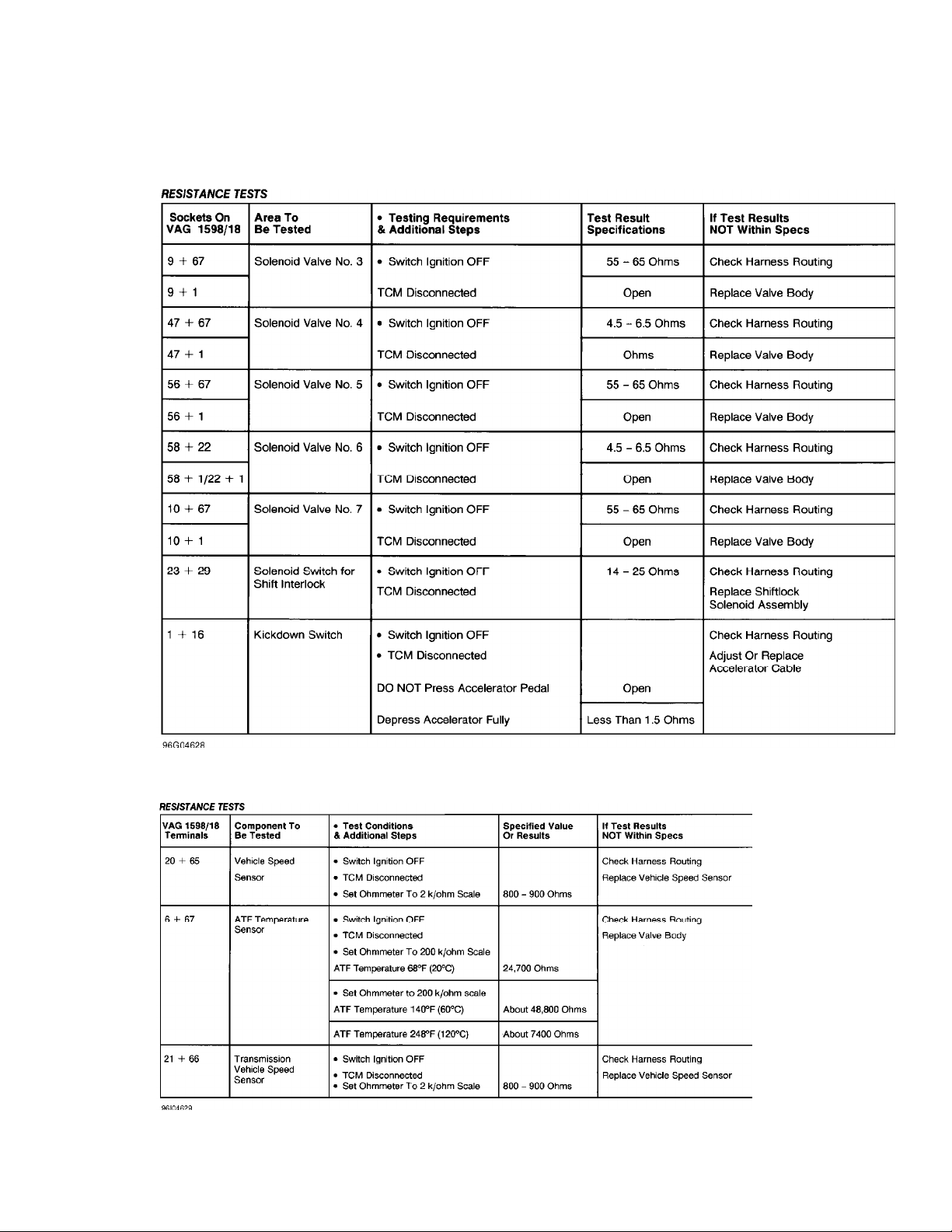
3) Measure voltage and resistance between specified sockets
on test box. See Figs. 10-13. If a problem is found, service harness
or components as necessary. If no problem is found, TCM may be
defective.
Thursday, August 19, 1999 11:28PM
Fig. 10: Testing TCM Harness & Components (1 Of 4)
Courtesy of Volkswagen United States, Inc.

AUTO TRANS DIAGNOSIS - 01M
Article Text (p. 15)
1996 Volkswagen Golf
For Volkswagen Technical Site
Copyright © 1998 Mitchell Repair Information Company, LLC
Thursday, August 19, 1999 11:28PM
Fig. 11: Testing TCM Harness & Components (2 Of 4)
Courtesy of Volkswagen United States, Inc.
AUTO TRANS DIAGNOSIS - 01M
Article Text (p. 16)
1996 Volkswagen Golf
For Volkswagen Technical Site
Copyright © 1998 Mitchell Repair Information Company, LLC
Thursday, August 19, 1999 11:28PM
Fig. 12: Testing TCM Harness & Components (3 Of 4)
Courtesy of Volkswagen United States, Inc.
Fig. 13: Testing TCM Harness & Components (4 Of 4)
Courtesy of Volkswagen United States, Inc.

AUTO TRANS DIAGNOSIS - 01M
Article Text (p. 17)
1996 Volkswagen Golf
For Volkswagen Technical Site
Copyright © 1998 Mitchell Repair Information Company, LLC
HYDRAULIC PRESSURE
Check operation of apply and brake clutches by air checking
fluid passages of valve body and transaxle case. Install Pressure
Gauge (VAG 1702) to transaxle pressure tap located near dipstick tube.
Check main hydraulic pressure under normal driving conditions. See
MAIN PRESSURE table. If main hydraulic pressures are not correct,
check for incorrect idle speed, problem with pump or sticking valves
in valve body. Repair as necessary.
MAIN PRESSURE
ДДДДДДДДДДДДДДДДДДДДДДДДДДДДДДДДДДДДДДДДДДДДДДДДДДДДДДДДДДДД
Application psi (Bar)
"D"
Idle RPM ............................... 49-55 (3.4-3.8)
2000 RPM (1) ....................... 146-164 (10.1-11.3)
"R"
Idle RPM .............................. 94-109 (6.5-7.5)
2000 RPM (1) ....................... 334-348 (23.0-24.0)
Thursday, August 19, 1999 11:28PM
(1) - With solenoid valve connector disconnected. After test,
reconnect solenoid valves and using appropriate scan tool,
erase trouble codes from memory.
ДДДДДДДДДДДДДДДДДДДДДДДДДДДДДДДДДДДДДДДДДДДДДДДДДДДДДДДДДДДД
STALL SPEED
CAUTION: DO NOT operate engine at stall speed for more than 5
seconds. If you need to repeat stall speed test, wait 20
seconds.
1) Engage parking brake and block drive wheels. Connect
tachometer to engine. Warm engine to normal operating temperature.
2) Firmly press brake pedal. Move gear selector to "D"
position. Open throttle to wide open throttle position. Note engine
speed and release throttle pedal.
3) Compare measured stall speed with stall speed
specification. See STALL SPEED SPECIFICATIONS table. If stall speed is
within range, test is complete.
4) If stall speed is up to 200 RPM too low, check engine
condition and adjustments. If stall speed is greater than 200 RPM too
low, torque converter is faulty. If stall speed is too high, check
1st-3rd apply clutch or one-way clutch for slipping or damage.
STALL SPEED SPECIFICATIONS
ДДДДДДДДДДДДДДДДДДДДДДДДДДДДДДДДДДДДДДДДДДДДДДДДДДДДДДДДДДДД
Application RPM
CLK ............................................ 2600-2900
CLB & CKZ ...................................... 2250-2550
ДДДДДДДДДДДДДДДДДДДДДДДДДДДДДДДДДДДДДДДДДДДДДДДДДДДДДДДДДДДД

AUTO TRANS DIAGNOSIS - 01M
Article Text (p. 18)
1996 Volkswagen Golf
For Volkswagen Technical Site
Copyright © 1998 Mitchell Repair Information Company, LLC
ON-VEHICLE SERVICE
DRIVE AXLE SHAFTS
See appropriate AXLE SHAFTS article in AXLE SHAFTS & TRANSFER
CASES section.
OIL COOLER FLUSHING
1) Remove external oil filter. Remove oil lines and allow
fluid to drain. Using pressurized solvent, flush remaining fluid and
debris from oil lines and cooler. Repeat flushing if necessary.
2) Use pressurized shop air to remove solvent from oil lines
and oil cooler. Install a new external oil filter.
TRANSAXLE COMPONENTS
Thursday, August 19, 1999 11:28PM
Following components may be serviced with transaxle in
vehicle. For removal and installation procedures, see
TRANSAXLE DISASSEMBLY.
* Drive Flanges
* External Oil Filter
* Gear Selector Lever
* Multifunction Switch, Speedometer Drive Shaft & Speed Sensor
* Oil Pan & Valve Body Assembly
* Planetary Gear Cover
REMOVAL & INSTALLATION
See appropriate AUTOMATIC TRANSMISSION REMOVAL article in
TRANSMISSION SERVICING section.
TORQUE CONVERTER
1) Remove torque converter. Check torque converter for any
wear or damage, and replace if necessary. If torque converter is being
reused, drain old fluid.
2) Extract ATF from torque converter using Torque Converter
Service Station (VAG 1358 A) and Probe (VAG 1358 A/1).
TRANSAXLE DISASSEMBLY
TRANSAXLE UNIT
1) Remove torque converter. Remove oil pan and valve body
assembly. Remove sealing plug from transaxle case. See Fig. 14.
2) Measure and record turbine shaft end play. See Fig. 15.
Remove oil pump bolts. Using two M8 bolts, remove oil pump from front
of transaxle. See Fig. 16.

AUTO TRANS DIAGNOSIS - 01M
Article Text (p. 19)
1996 Volkswagen Golf
For Volkswagen Technical Site
Copyright © 1998 Mitchell Repair Information Company, LLC
3) Remove all clutches with support tube, 2nd-4th gear clutch
plates, springs and spring caps together. See Figs. 17 and 18.
4) Lock drive shell in place by inserting a screwdriver
through hole of large sun gear into side of transaxle case. See
Fig. 19. Loosen and remove small planetary drive shaft bolt, washer
and shim. See Fig. 20. Remove small planetary drive shaft.
5) Remove large drive shaft and sun gear. Remove Vehicle
Speed Sensor (VSS) from transaxle case. Remove supporting tube and
one-way clutch circlips. Remove one-way clutch assembly.
6) Remove planetary carrier with dished spring. Remove
reverse brake clutch assembly. See Figs. 17, 20 and 21. DO NOT remove
input gear assembly, unless bearing or gear damage is present.
Thursday, August 19, 1999 11:28PM
Fig. 14: Exploded View Of Oil Pan & Valve Body
Courtesy of Volkswagen United States, Inc.

AUTO TRANS DIAGNOSIS - 01M
Article Text (p. 20)
1996 Volkswagen Golf
For Volkswagen Technical Site
Copyright © 1998 Mitchell Repair Information Company, LLC
Thursday, August 19, 1999 11:28PM
Fig. 15: Checking Turbine Shaft End Play
Courtesy of Volkswagen United States, Inc.
Fig. 16: Removing Oil Pump
Courtesy of Volkswagen United States, Inc.

AUTO TRANS DIAGNOSIS - 01M
Article Text (p. 21)
1996 Volkswagen Golf
For Volkswagen Technical Site
Copyright © 1998 Mitchell Repair Information Company, LLC
Thursday, August 19, 1999 11:28PM
Fig. 17: Exploded View Of Transaxle Components
Courtesy of Volkswagen United States, Inc.
Fig. 18: Removing Turbine Shaft With 2nd-4th Brake Clutch & 1st3rd Apply Clutch
Courtesy of Volkswagen United States, Inc.
 Loading...