


Volkswagen Golf IV User Manual

Golf/Bora No. 3/1
Current flow diagram
1.4 ltr./55kW 4AV, engine code AHW,
1.4 ltr./55kW 4AV, engine code AKQ,
from October 1997
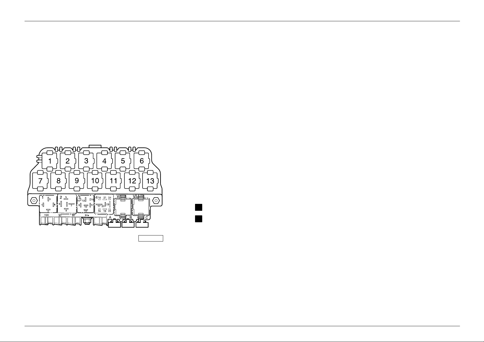
For alternatives to relay and fuse positions as well as multi-pin connector wiring-see ”Fitting locations” section.
97–14163
Relay locations on 13 position additional
relay carrier , above relay plate:
Relay locations on relay plate:
Relief relay for X contact (18)2
Fuel pump relay (167)
4
Note:
The number in brackets behind the part
designation denotes the control number on the
housing.
Fuse colours
30 A – green
25 A – white
20 A – yellow
15 A – blue
10 A – red
7.5 A – brown
5 A – beige
3 A – lilac
Edition 12.99

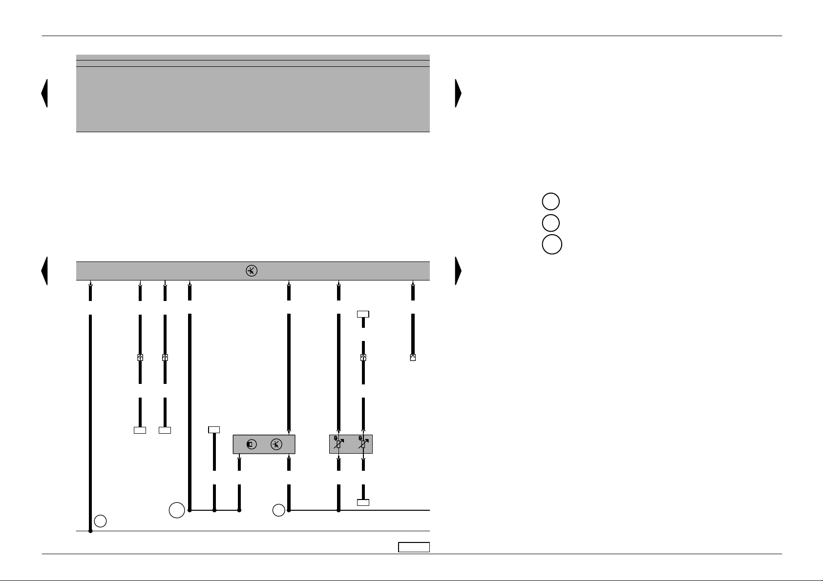
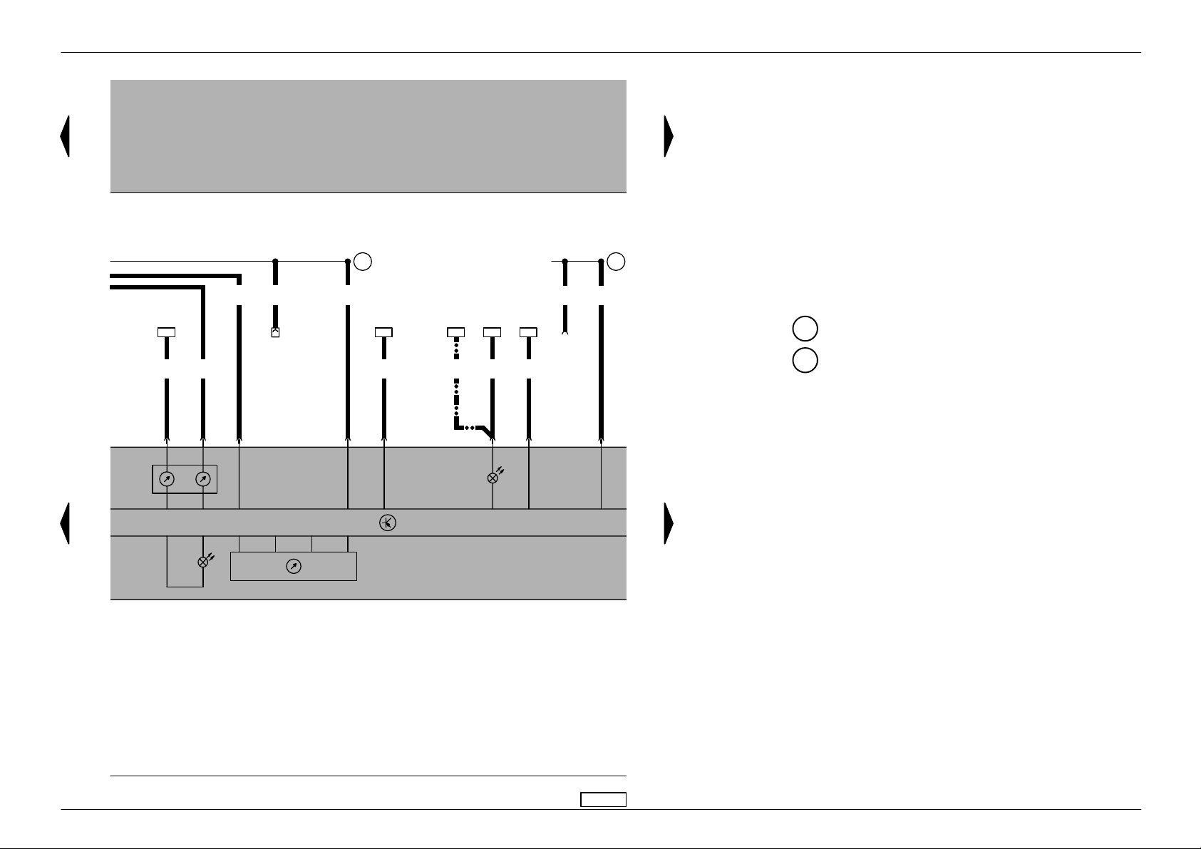
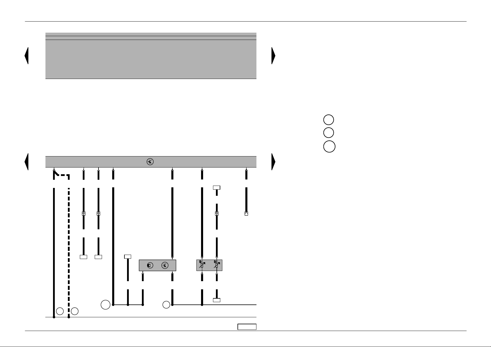
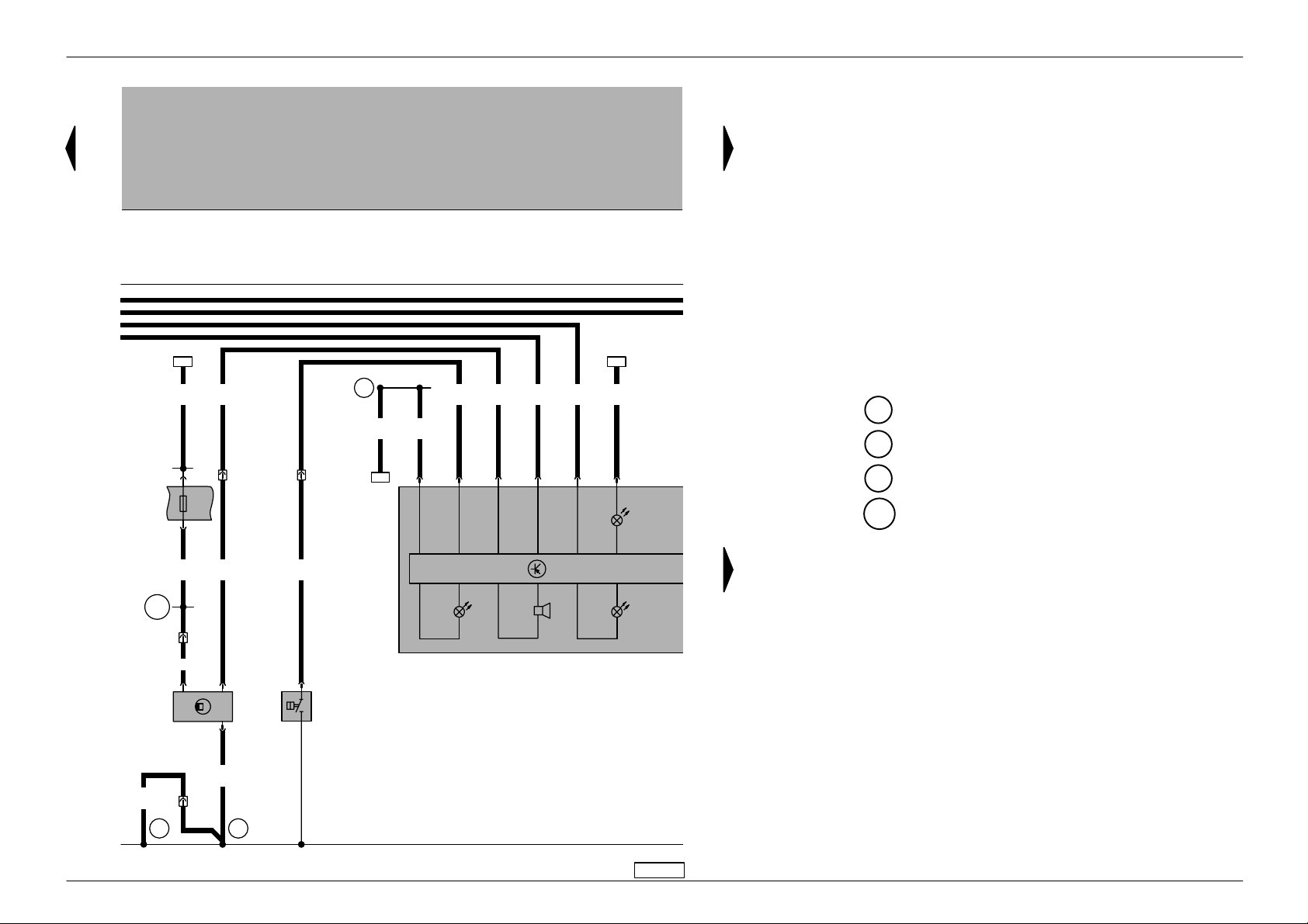
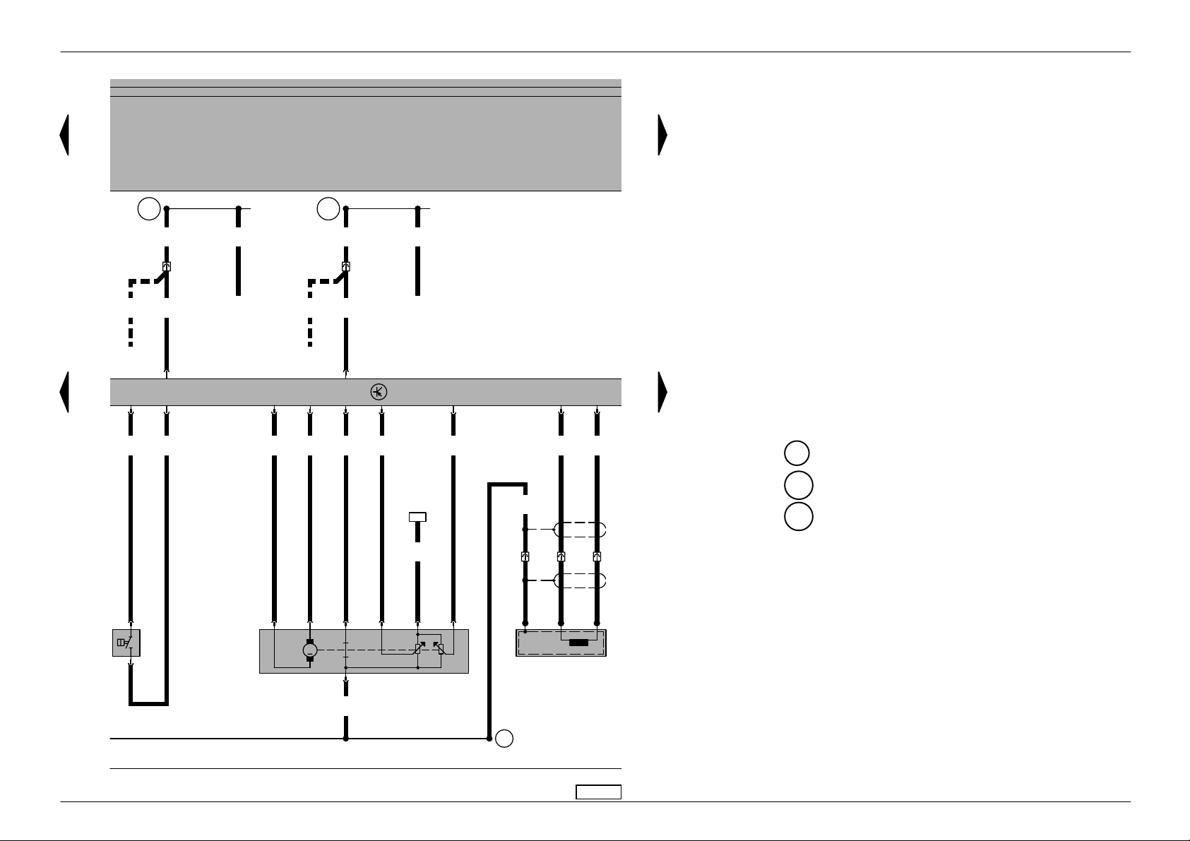
Golf/Bora No. 3/2
Current flow diagram
Alternator, starter
31
0,5
a
J
5
S177
110A
59
5/31
2
7/30
500 502
16,0
ro
4
S176
110A
b
6,0
ro
2
S163
50A
/+
A
/50b
D
2,5
ro/sw
/+
A
6/3
T
9
3
S1/1
br
A17
0,35
bl
122
0,5
bl
123
0,35
bl
✱
4/2
T
2e/2
T
1,0
bl
/50
D
16,0
sw
A – Battery
B – Starter
C – Alternator
C1 – Voltage regulator
D – Ignition/starter switch
J59 – X contact relief relay
S163 – Fuse -2- (30) in battery fuse holder
S176 – Fuse -4- (30) in battery fuse holder
S177 – Fuse -5- (30) in battery fuse holder
T2e – 2-pin connector, near starter (on vehicles not
fitted with air conditioner)
T4 – 4-pin connector, near starter (on vehicles fitted
with air conditioner)
T6 – 6-pin connector, brown, in protective housing
for connectors, left in plenum chamber
81 – Earth connection -1-, in dash panel wiring
harness
500 – Screw connection -1- (30), on relay plate
502 – Screw connection -1- (30a), on relay plate
A17 – Connection (61), in dash panel wiring harness
(discontinued for vehicles from May 1998)
✱
– For vehicles from May 1998
● ●
–
– – Discontinued for vehicles from May 1998
0,5
bl
B+
D+
G
C
1
C
81
12345678
2,5
35,0
ro/sw
sw
5030
B
M
91011121314
97-26882
ws = white
sw = black
ro = red
br = brown
gn = green
bl = blue
gr = grey
li = lilac
ge = yellow
or = orange
Edition 12.99

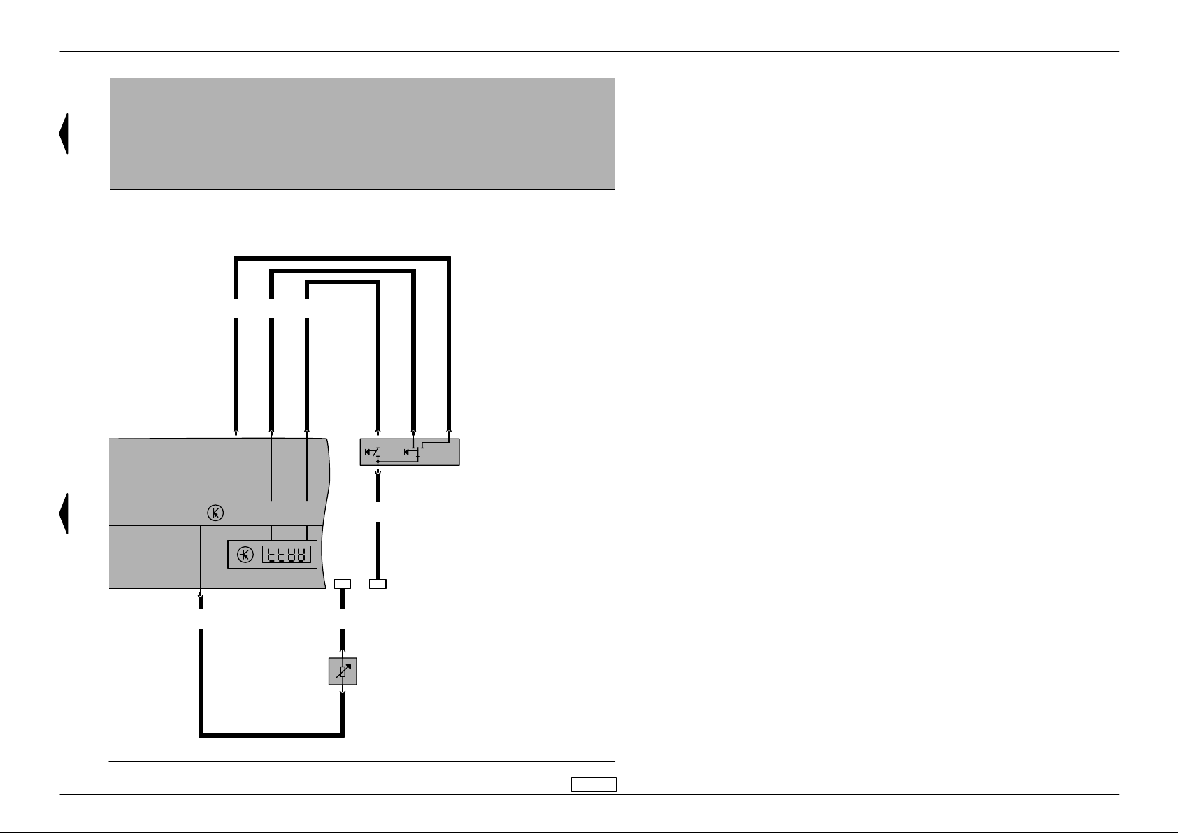
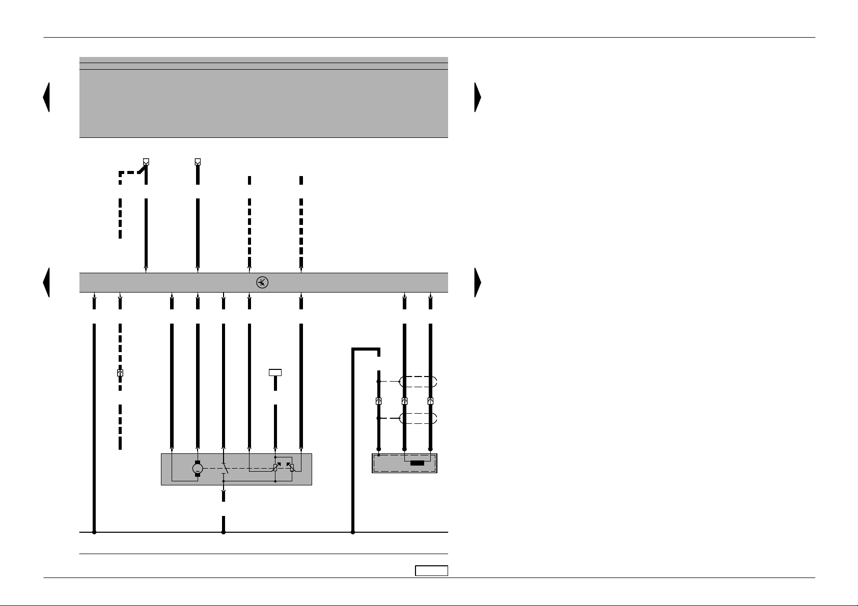
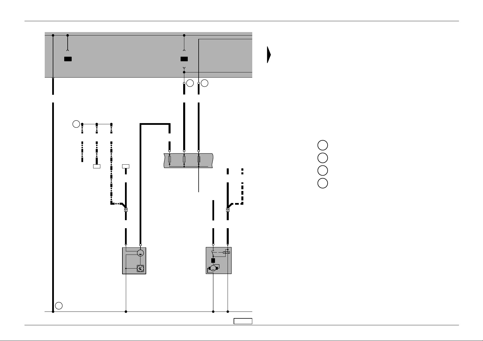
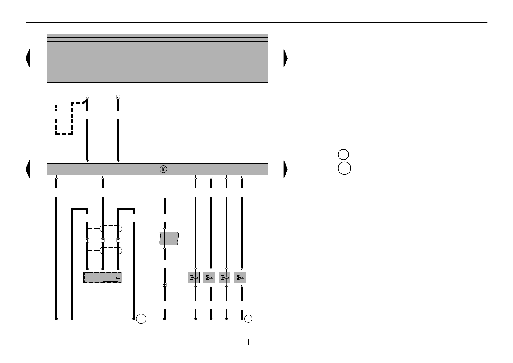
Golf/Bora No. 3/3
Current flow diagram
4A V control unit (injection system), ignition system
31
a
b
501
6,0
ro
2,5ro6,0
ro
/30
D
A98
A32
1,0
ro/li
T
1,0 ro/gn
10a
10
1,0
ro
6/4
S10
10A
1,5
sw/li
29a
S229
15A
29
1,5
sw
A2
0,5
sw
1,5
sw/li
10a/8
T
/15
D
2,5
sw
T4a/2
2,5
sw
J
152
N
448
1,5
sw/li
0,5
gn/br
A104
6/1
T
T80/3
T80/71
T4a/1
0,5
gn/ge
T80/1
T80/78
T4a/3
31
a
D – Ignition/starter switch
J448 – 4AV control unit (injection system), centre in
plenum chamber
N152– Ignition transformer
P – Spark plug connector
Q – Flame plug
S10 – Fuse in relay plate fuse box
S229 – Fuse in fuse holder
T4a – 4-pin connector
T6 – 6-pin connector, brown, in protective housing
for connectors, left in plenum chamber
T10a – 10-pin connector, in cable channel left in engine
compartment
T80 – 80-pin connector
85 – Earth connection -1-, in engine compartment
wiring harness
501 – Screw connection -2- (30), on relay plate
A2 – Positive (+) connection (15), in dash panel
wiring harness
A32 – Positive connection (30), in dash panel wiring
harness
A98 – Positive connection -4- (30), in dash panel
wiring harness
A104 – Positive connection -2- (15), in dash panel
wiring harness
85
15 16 17 18 19 20 21 22
99
T4a/4
2,5
br
85
23 24 25 26 27 28
P
Q
97-24159
ws = white
sw = black
ro = red
br = brown
gn = green
bl = blue
gr = grey
li = lilac
ge = yellow
Edition 12.98
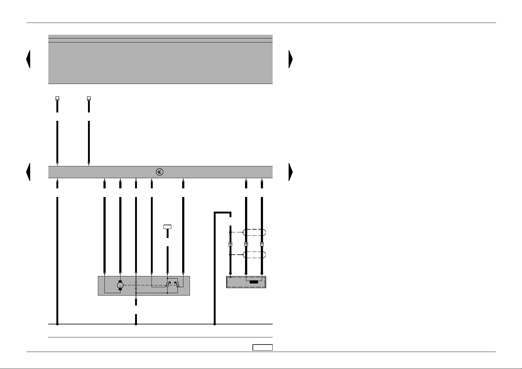
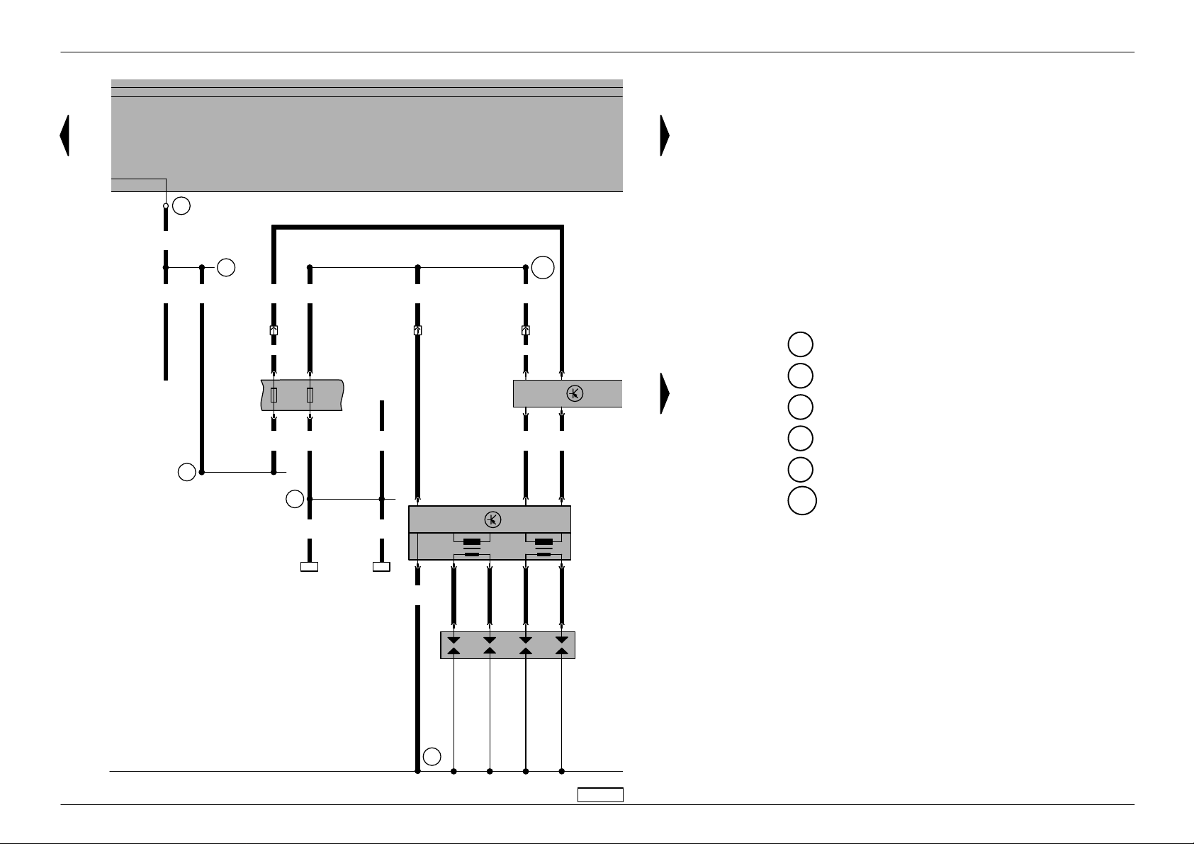
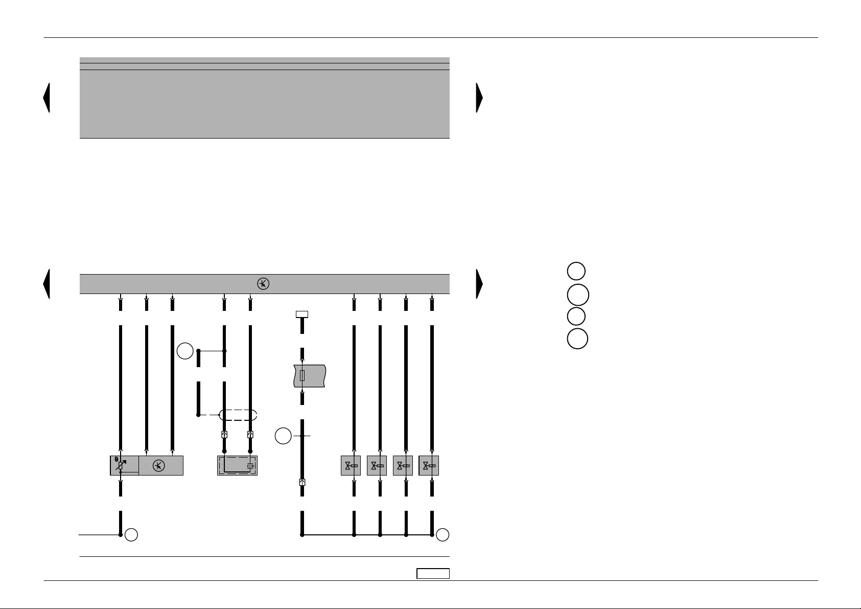
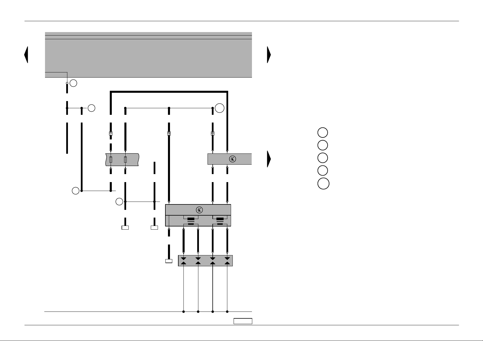
Golf/Bora No. 3/4
Current flow diagram
4A V control unit (injection system), coolant temperature sender, Hall sender
G2 – Coolant temperature sender
G40 – Hall sender
G62 – Coolant temperature sender
J448 – 4AV control unit (injection system), centre in
plenum chamber
T10 – 10-pin connector, orange, in protective housing
for connectors, left in plenum chamber
T10a – 10-pin connector, in cable channel left in engine
compartment
T80 – 80-pin connector
10 – Earth point, in plenum chamber
220 – Earth connection (sender earth), in engine
wiring harness
D101 – Connection -1-, in engine compartment wiring
harness
✱✱
– Fuel consumption signal from engine control
✱✱✱
unit, for MFI only
– Connection for radiator fan control unit
0,5
ws
T80/13
31
a
31
a
448
J
2,5
T80/2
br
0,5
gr/ws
T80/19
W
0,5
gn/ws
T80/18
0,5
li/ro
T80/64
0,5
li/ge
T80/76
0,5
bl
T80/53
114
10/1
0,35
gn/ws
120
10/2
T
✱✱
D101
50
0,5
li/ro
0,5
li/ro
1
G40
T
0,35
gr/ws
124
10
29 30 31 32 33 34 35 36
0,35
li
10a/4
T
0,5
li
2
62
G
3
0,5
br/bl
220
37 38 39 40 41 42
0,5
br/bl
4
3
2
G
1
2
0,5
br/ws
94
✱✱✱
T
97-24160
10/4
ws = white
sw = black
ro = red
br = brown
gn = green
bl = blue
gr = grey
c
li = lilac
ge = yellow
Edition 12.98
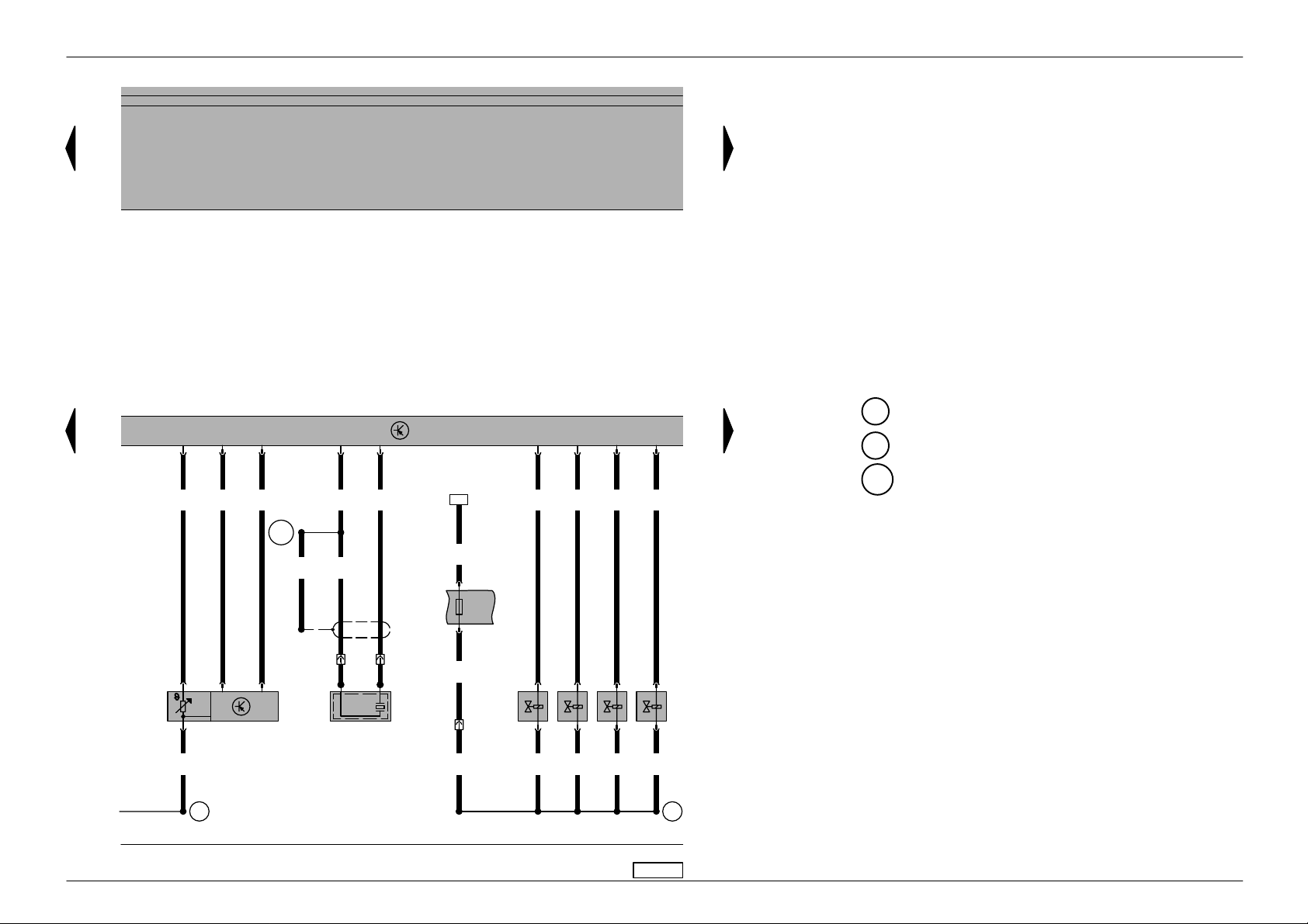
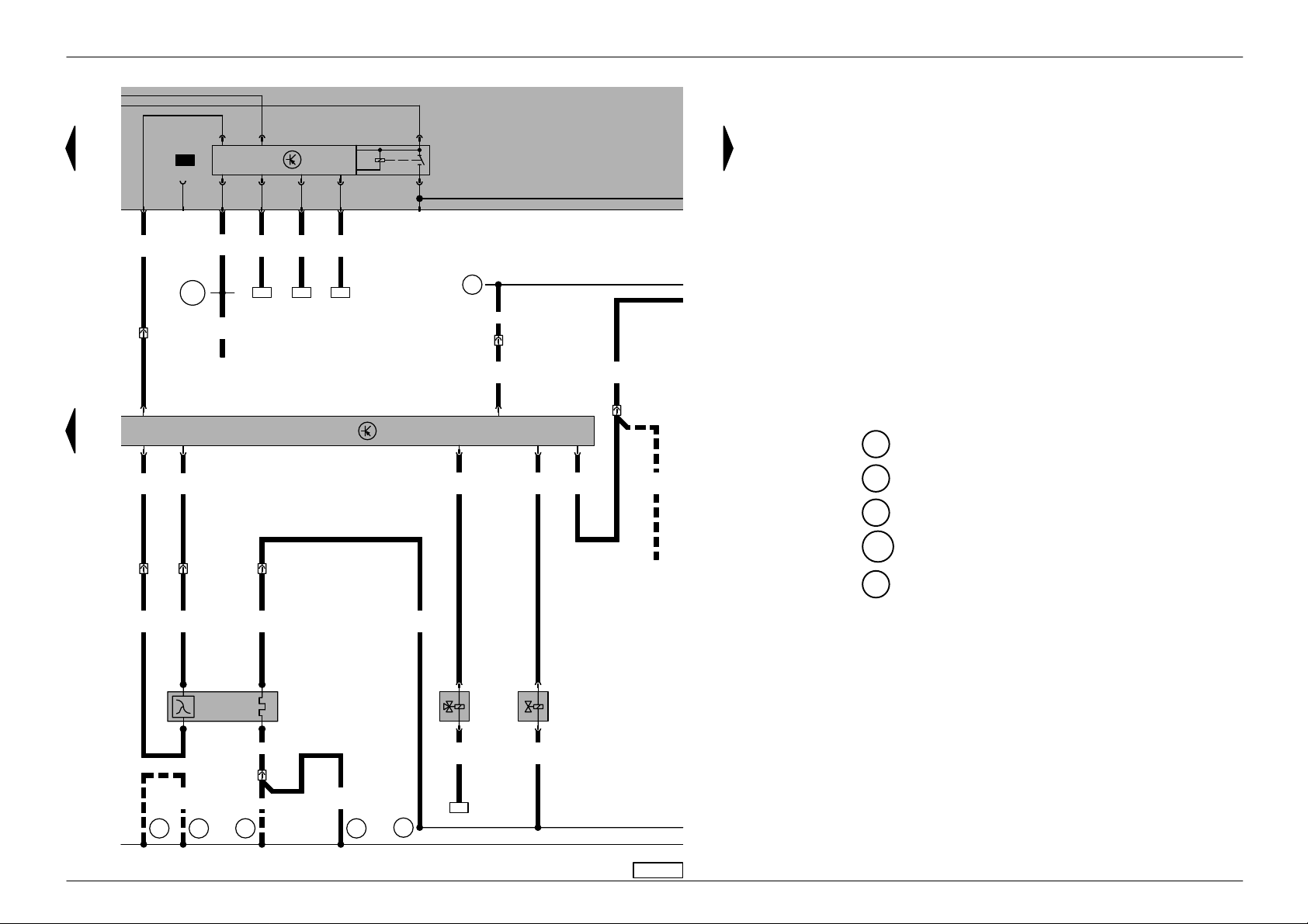
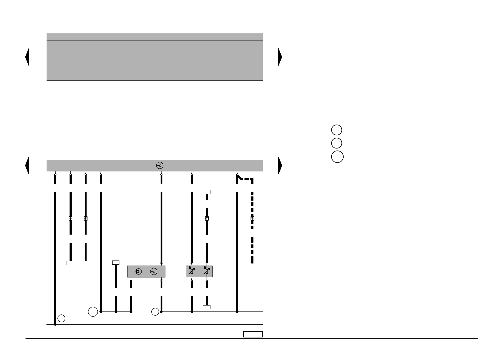
Golf/Bora No. 3/5
Current flow diagram
4AV control unit (injection system), throttle valve
31
a
0,5
gn
T
✱✱
10/7
0,5
bl/ro
T
✱✱
10/8
31
a
control part, engine speed sender
F60 – Idling switch
G28 – Engine speed sender
G69 – Throttle valve potentiometer
G88 – Throttle valve positioner potentiometer
J226 – Starter inhibitor and reversing light relay, above
central electrics
J338 – Throttle valve control unit
J448 – 4AV control unit (injection system), centre in
plenum chamber
T3 – 3-pin connector, near intake manifold
T8 – 8-pin connector
T10 – 10-pin connector, orange, in protective housing
for connectors, left in plenum chamber
T80 – 80-pin connector
V60 – Throttle valve positioner
T80/8
T80/67
1,0
br/bl
c
43 44 45 46 47 48 49 50
T80/10
T80/59
T80/69
1,0
1,0ws0,5
li
li/ws
T8/1 T8/2 T8/3 T8/5 T8/4
M
T8/7
60
60
F
V
0,5
br/bl
0,5
li/sw
T80/75
448
J
✱✱
– Air conditioning system connection
– – – – For vehicles with automatic gearbox only
T80/56
T80/74T80/66
0,5
li/ge
0,5
34
0,5
li/ro
T8/8
338
J
G
88
G
69
51 52 53 54 55 56
ge
T80/63
0,5
0,5
sw
ws
3/3T3/2T3/1
T
28
G
97-26883
ws = white
sw = black
ro = red
br = brown
gn = green
bl = blue
gr = grey
c
li = lilac
ge = yellow
or = orange
Edition 12.99
Golf/Bora No. 3/6
Current flow diagram
4A V control unit (injection system), intake manifold
pressure sender , intake manifold temperature sender, knock sensor, injectors
G42 – Intake air temperature sender
G61 – Knock sensor I
G71 – Intake manifold pressure sender
J448 – 4AV control unit (injection system), centre in
plenum chamber
N30 – Injector, cylinder 1
N31 – Injector, cylinder 2
N32 – Injector, cylinder 3
N33 – Injector, cylinder 4
S232 – Fuse in fuse holder
T2 – 2-pin connector, left on cylinder head
T10a – 10-pin connector, in cable channel left in engine
compartment
T80 – 80-pin connector
220 – Earth connection (sender earth), in engine
wiring harness
D95 – Connection (injectors), in engine compartment
wiring harness
D102 – Connection -2-, in engine compartment wiring
harness
1,0
li/bl
31
a
T80/65T80/73 T80/58T80/80
31
a
448
J
T80/60
0,5
bl
T80/68
1,0
1,0
91
li
li/gn
1,0
li/ro
0,5
bl/gn
0,5
li/ro
T80/62T80/54
T80/61
0,5
ge/sw
1,0
sw
D102
0,5
0,5
sw
gr
2/2T2/1
T
4
32
1
42
G
0,5
br/bl
c
57 58 59 60 61 62 63 64
220
71
G
G
4,0
bl
32
S232
10A
32a
1,5
ro/li
31
30
N
N
N
2
2
33
32
N
2
2
ws = white
10a/5
1,0
ro/li
T
1,0
ro/li
61
1
1
1,0
1,0
ro/li
ro/li
1
1
1,0
ro/li
sw = black
ro = red
br = brown
gn = green
bl = blue
gr = grey
D95
li = lilac
ge = yellow
or = orange
65 66 67 68 69 70
97-24162
Edition 12.99

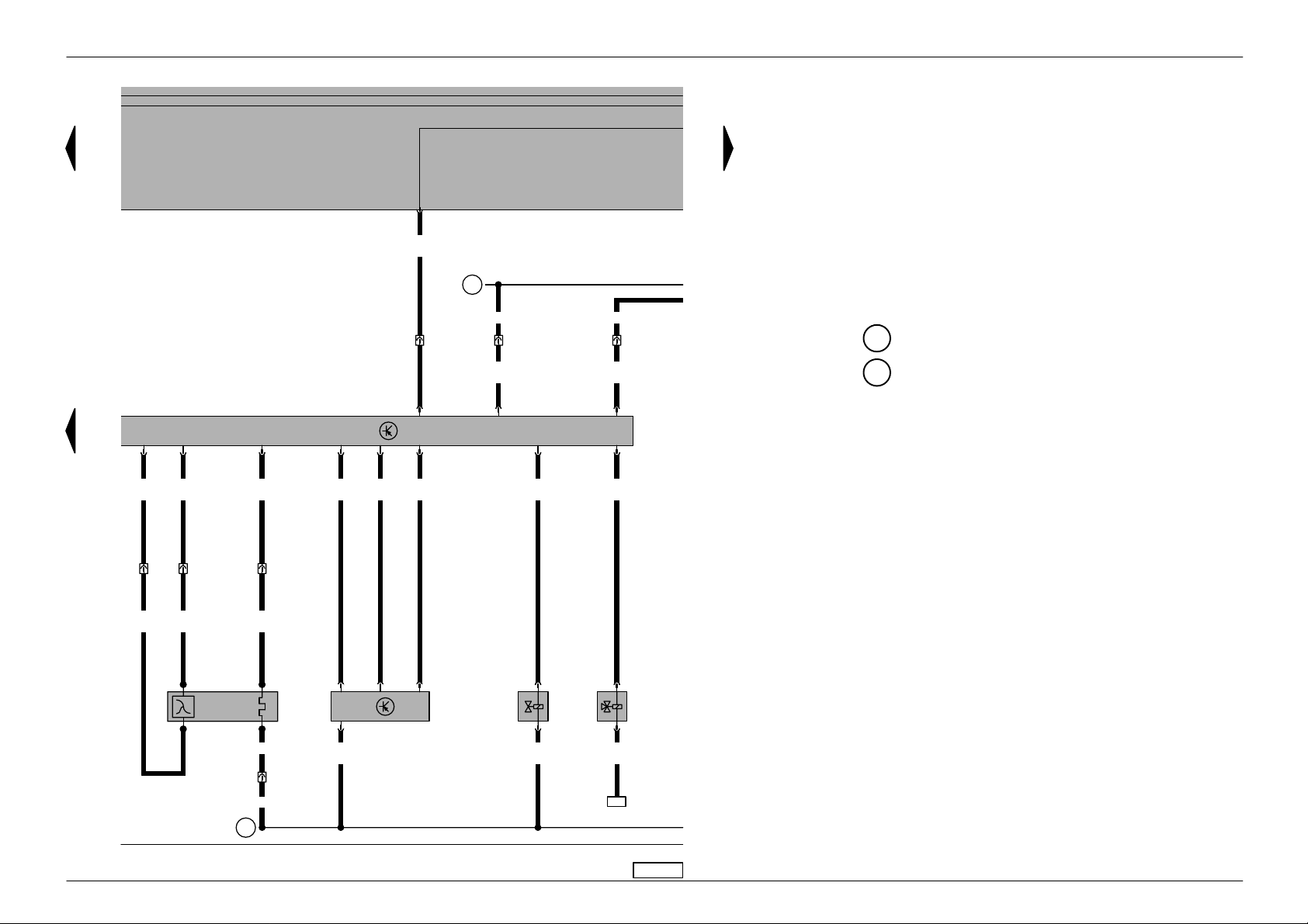
Golf/Bora No. 3/7
Current flow diagram
4A V control unit (injection system), Lambda probe,
31
a
S3/6
0,5
li/ws
A27
1,0
br
T80/25
1,0
sw
T80/26
0,35 bl/ws
10/3
T
J
448
T80/4
1,0
li
T80/72
0,5
bl/ws
T
T80/20
10/6
1,0
li/ro
0,35 gn/br
T80/15
0,5
gn/br
10/9
T
T80/6
31
a
d
e
f
activated charcoal filter system solenoid valve, exhaust gas recirculation valve
G39 – Lambda probe
J448 – 4AV control unit (injection system), centre in
plenum chamber
N18 – Exhaust gas recirculation valve
N80 – Activated charcoal filter system solenoid valve I
T4b – 4-pin connector, in centre of engine
compartment
T10 – 10-pin connector, orange, in protective housing
for connectors, left in plenum chamber
T80 – 80-pin connector
10 – Earth point, in plenum chamber
A27 – Connection (speed signal), in dash panel wiring
harness
E30 – Connection (87a), in engine wiring harness
4b/3
4b/4
T
T
1,0
1,0
sw
gr
39
G
71 72 73 74 75 76 77 78
T
1,0
ws
1,0 ws
T
1,0 br/sw
10
4b/1
4b/2
E30
1,5
bl/ro
1,5
bl/ge
2
80
N
1
2
18
N
1
1,0
ge/sw
88
79 80 81 82 83 84
97-26884
ws = white
sw = black
ro = red
br = brown
gn = green
bl = blue
gr = grey
li = lilac
g
ge = yellow
or = orange
Edition 12.99

Golf/Bora No. 3/8
Current flow diagram
Fuel pump, fuel gauge sender , coolant shortage in-
31
a
d
16/85
17/30
J17
19/86
23/87
S3/3
0,5
sw
e
f
4,0
bl
2,5
bl/ge
43
S243
10A
43a
4,0
bl
1,0
ge/sw
34
S234
10A
34a
20
4,0
bl
1,5
bl/ro
504
28
S228
15A
28a
4,0
bl
65
21
4
2018
22
24
0,35
br/ws
S3/2S3/4
133
0,35
br/ws
S3/5S2/5 S3/1
A99
0,35
li/sw
134
0,35
br/ws
0,35
li/ro
e
f
h
i
j
dicator sender
G – Fuel gauge sender
G6 – Fuel pump (pre-supply pump)
G32 – Coolant shortage indicator sender
J17 – Fuel pump relay
S228 – Fuse in fuse holder
S234 – Fuse in fuse holder
S243 – Fuse in fuse holder
T6 – 6-pin connector, brown, in protective housing
for connectors, left in plenum chamber
T10a – 10-pin connector, in cable channel left in engine
compartment
135 – Earth connection -2-, in dash panel wiring
harness
269 – Earth connection (sender earth) -1-, in dash
panel wiring harness
504 – Screw connection -1- (87F), on relay plate
A99 – Connection -1- (87), in dash panel wiring
harness
A100 – Connection -2- (87), in dash panel wiring
harness
E30 – Connection (87a), in engine wiring harness
A100
1,0
1,0
ge/sw
ge/sw
6/5
6/6
1,0
ge/sw
79
T
10a/6
13
M
G
6
4
1,5
br
135
T
T
g
85 86 87 88 89 90 91 92
E30
269
1,0
0,5
br/ws
br/ws
10a/9
T
0,5
br/ws
G
2
40
93 94 95 96 97 98
0,5
br/ws
1
32
G
2
97-24164
ws = white
sw = black
ro = red
br = brown
gn = green
bl = blue
gr = grey
li = lilac
ge = yellow
or = orange
Edition 12.99
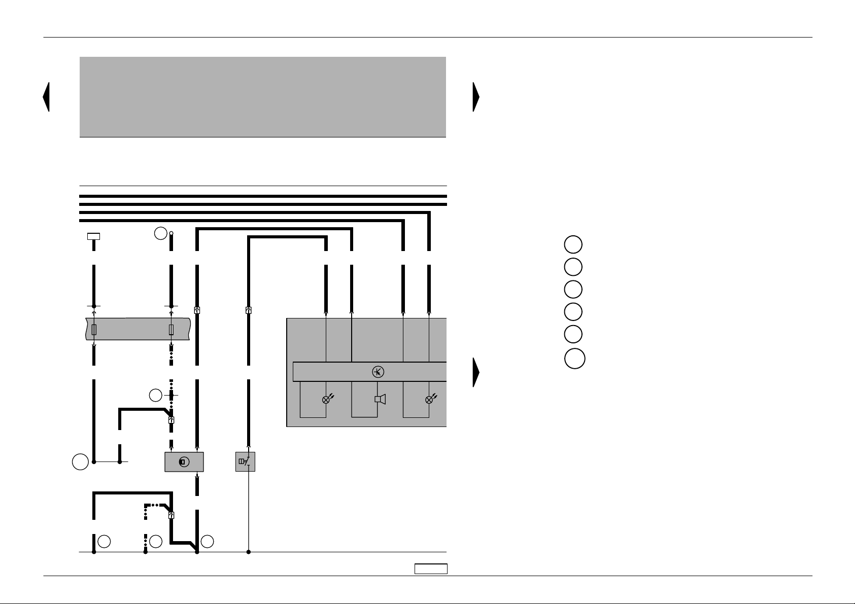
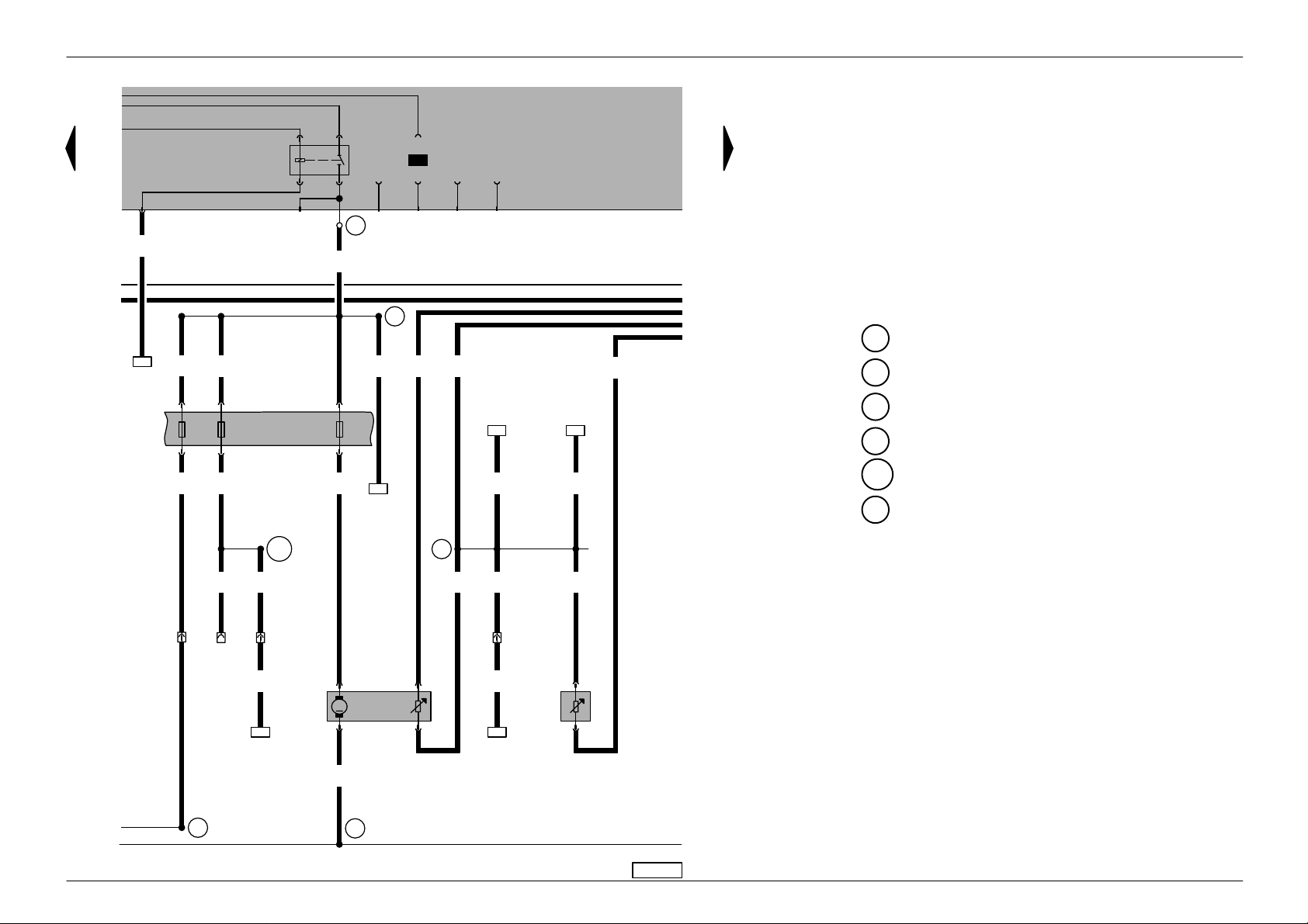
Golf/Bora No. 3/9
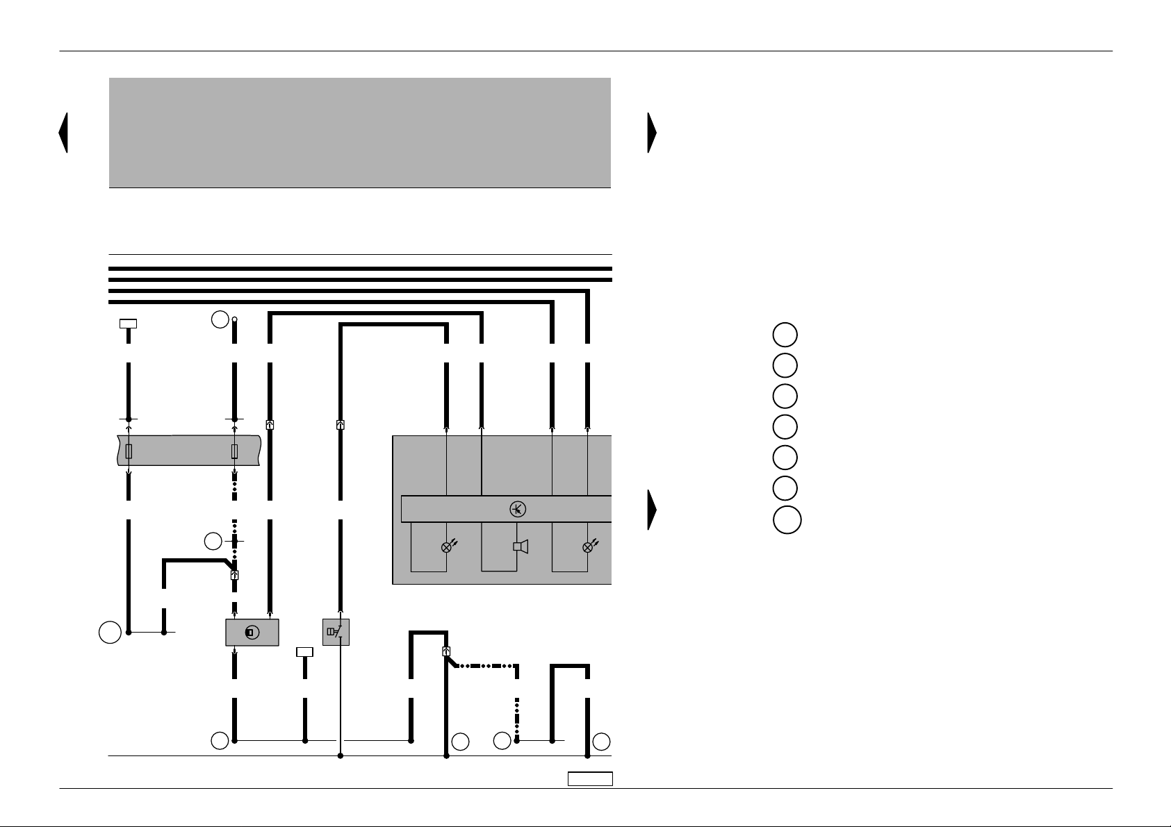
Current flow diagram
Dash panel insert, optical and acoustic oil pressure
warning, speedometer sender, coolant tempera-
e
f
h
i
j
B163
22
2,5
sw
1,0
sw/gn
2,5
br
7
S7
10A
7a
✱
e
f
h
503
10,0
sw/ge
2
S2
10A
2a
0,35
gn
T
10a/10
T
10a/1
0,35
gn/sw
T32/10
0,35
gn
0,35
li/ro
T32/22
0,35
br/ws
T32/7T32/28
J285
1,0
0,5
sw/ws
ws/bl
A1
✱
1,0
sw/gn
T
1,0 sw/ws
12
10a/
2
G22
3
1,0
br
10a/
179
T
7
85
2,5
br
10
0,5
gn/sw
3
K
1
F
H3
28
K
ws = white
sw = black
ro = red
br = brown
gn = green
bl = blue
gr = grey
li = lilac
ge = yellow
ture/coolant shortage warning lamp
F1 – Oil pressure switch
G22 – Speedometer sender (Hall sender on gearbox)
H3 – Buzzer
J285 – Control unit with display in dash panel insert
K3 – Oil pressure warning lamp
K28 – Coolant temperature/coolant shortage warning
lamp
S2 – Fuse in relay plate fuse box
S7 – Fuse in relay plate fuse box
T10a – 10-pin connector, in cable channel left in engine
compartment
T32 – 32-pin connector, blue
10 – Earth point, in plenum chamber
85 – Earth connection -1-, in engine compartment
wiring harness
179 – Earth connection, in left headlight wiring
harness
503 – Screw connection (75x), on relay plate
A1 – Positive (+) connection (30a), in dash panel
wiring harness
B163 – Positive connection -1- (15), in interior wiring
harness
✱
– For vehicles from May 1998
● ●
–
– – Discontinued on vehicles from May 1998
99 100 101 102 103 104 105 106 107 108 109 110 111 112
97-24165
Edition 12.98
Golf/Bora No. 3/10
Current flow diagram
Dash panel insert, coolant temperature gauge, fuel
gauge , rev. counter, self–diagnosis connection
G1 – Fuel gauge
G3 – Coolant temperature gauge
G5 – Rev. counter
J285 – Control unit with display in dash panel insert
K2 – Alternator warning lamp
K105 – Reserve fuel warning lamp
T12a – 12-pin connector, connection for Climatronic
only
T16 – 16-pin connector, centre in dash panel,
self-diagnosis connection
T32 – 32-pin connector, blue
T32a – 32-pin connector, green
0,35
bl/ws
A27
0,5
gr/ws
0,35
gr/ws
A76
e
f
h
0,35
gn/br
0,35
bl/ws
40
0,35
0,35
li/sw
li
T32/11T32/5T32/8
G
3
G
1
12a/10
T
32 6
0,35
gn/ws
✱✱
T32a/32T32/3
4
0,35
bl
K2
0,35
bl
31
0,35
gr/ws
✱
T16/7
K
W
T32a/5T32/12
K
T32/25
A27 – Connection (speed signal), in dash panel wiring
harness
A76 – Connection (diagnosis wire K), in dash panel
wiring harness
✱
– For vehicles from May 1998
✱✱
– Fuel consumption signal from engine control
unit, for MFI only
● ●
–
– – Discontinued on vehicles from May 1998
J285
105
K
G5
ws = white
sw = black
ro = red
br = brown
gn = green
bl = blue
gr = grey
li = lilac
ge = yellow
114 115 116 117 118 119 120 121 122 123 124 125 126113
97-24166
Edition 12.98
Golf/Bora No. 3/11
Current flow diagram
Dash panel insert, multi-function indicator, ambient temperature display
E86 – Multi–function display call–up button
E109 – Multi–function display, memory switch
G17 – Ambient temperature sensor
J119 – Multi–function display
J285 – Control unit with display in dash panel insert
T6e – 6-pin connector
T32a – 32-pin connector, green
J285
0,35
br/ge
T32a/26
0,35bl0,35
bl/gn
T32a/
24
J119
T32a/
23
0,35
bl/gr
T32a/25
94
0,35
br/ws
ϑ
E109
2
1
0,35
br/ws
G17
96
T6e/4
T6e/3
T6e/2
E86
T6e/1
ws = white
sw = black
ro = red
br = brown
gn = green
bl = blue
gr = grey
li = lilac
ge = yellow
128 129 130 131 132 133 134 135 136 137 138 139 140127
97-24167
Edition 12.98
Golf/Bora No. 63/1
Current flow diagram
1.4 ltr./55kW 4AV, engine code AHW,
1.4 ltr./55kW 4AV, engine code AKQ,
from August 1998
For alternatives to relay and fuse positions as well as multi-pin connector wiring-see ”Fitting locations” section.
97–14163
Relay locations on 13 position additional
relay carrier , above relay plate:
Relay locations on relay plate:
2 X contact relief relay (18)
4 Fuel pump relay (409)
Note:
The number in brackets behind the part
designation denotes the control number on the
housing.
Fuse colours
30 A – green
25 A – white
20 A – yellow
15 A – blue
10 A – red
7.5 A – brown
5 A – beige
3 A – lilac
Edition 12.98

Golf/Bora No. 63/2
Current flow diagram
Alternator, starter
31
0,5
a
J
5
S177
110A
5/31
2
59
16,0
ro
7/30
500
4
S176
110A
502
6,0
ro
74
/50b
D
1,5
2,5
ro/sw
ro/sw
2
J226 /8
J226 /6
0,5
ro/sw
A
35,0
sw
A41
2,5
ro/sw
✱
2,5
ro/sw
6/3
T
/+
S163
50A
/+
A
2,5
ro/sw
b
9
3
S1/1
br
16,0
sw
111
0,35
bl
4/2
T
2e/2
T
0,5
bl
A – Battery
B – Starter
C – Alternator
C1 – Voltage regulator
D – Ignition/starter switch
J59 – X contact relief relay
J226 – Starter inhibitor and reversing light relay, on 13
position additional relay carrier
S163 – Fuse -2- (30), in battery fuse holder
S176 – Fuse -4- (30), in battery fuse holder
S177 – Fuse -5- (30), in battery fuse holder
T2e – 2-pin connector, near starter (on vehicles not
fitted with air conditioner)
T4 – 4-pin connector, near starter (on vehicles fitted
with air conditioner)
T6 – 6-pin connector, brown, in protective housing
for connectors, left in plenum chamber
81 – Earth connection -1-, in dash panel wiring
harness
500 – Screw connection -1- (30), on relay plate
502 – Screw connection -1- (30a), on relay plate
A41 – Positive (+) connection (50), in dash panel
wiring harness
✱
– For vehicles with manual gearbox only
– – – – For vehicles with automatic
gearbox only
D+
B+
G
C
1
C
81
12345678
5030
B
M
91011121314
97-24300
ws = white
sw = black
ro = red
br = brown
gn = green
bl = blue
gr = grey
li = lilac
ge = yellow
Edition 12.98
Golf/Bora No. 63/3
Current flow diagram
4A V control unit (injection system), ignition system
31
a
b
501
6,0
ro
2,5ro6,0
ro
/30
D
A98
A32
1,5
sw/li
T
1,0 ro/gn
10a
10
1,0
ro
6/4
S10
10A
1,5
sw/li
29a
S229
15A
29
1,5
sw
A2
0,5
sw
1,5
sw/li
10a/8
T
/15
D
2,5
sw
T4a/2
2,5
sw
J
152
N
448
1,5
sw/li
1,0 ro/li
0,5
gn/br
A104
6/1
T
T80/3
T80/71
T4a/1
0,5
gn/ge
T80/1
T80/78
T4a/3
31
a
D – Ignition/starter switch
J448 – 4AV control unit (injection system), centre in
plenum chamber
N152– Ignition transformer
P – Spark plug connector
Q – Flame plug
S10 – Fuse in relay plate fuse box
S229 – Fuse in fuse holder
T4a – 4-pin connector
T6 – 6-pin connector, brown, in protective housing
for connectors, left in plenum chamber
T10a – 10-pin connector, in cable channel left in engine
compartment
T80 – 80-pin connector
85 – Earth connection -1-, in engine compartment
wiring harness
501 – Screw connection -2- (30), on relay plate
A2 – Positive (+) connection (15), in dash panel
wiring harness
A32 – Positive connection (30), in dash panel wiring
harness
A98 – Positive connection -4- (30), in dash panel
wiring harness
A104 – Positive connection -2- (15), in dash panel
wiring harness
76
15 16 17 18 19 20 21 22
100
T4a/4
2,5
br
85
23 24 25 26 27 28
P
Q
97-24301
ws = white
sw = black
ro = red
br = brown
gn = green
bl = blue
gr = grey
li = lilac
ge = yellow
Edition 12.98
Golf/Bora No. 63/4
Current flow diagram
4A V control unit (injection system), coolant temperature sender, Hall sender
G2 – Coolant temperature sender
G40 – Hall sender
G62 – Coolant temperature sender
J448 – 4AV control unit (injection system), centre in
plenum chamber
T10 – 10-pin connector, orange, in protective housing
for connectors, left in plenum chamber
T10a – 10-pin connector, in cable channel left in engine
compartment
T80 – 80-pin connector
10 – Earth point, in plenum chamber
220 – Earth connection (sender earth), in engine
wiring harness
D101 – Connection -1-, in engine compartment wiring
harness
✱
– For vehicles with manual gearbox only
✱✱
– Fuel consumption signal from engine control
unit, for MFI only
✱✱✱
– Connection for radiator fan control unit
– – – – For vehicles with automatic gearbox only
0,5
ws
T80/13
✱✱✱
31
a
31
a
448
J
2,5
T80/2
2,5
br
br/ge
0,5
gr/ws
T80/19
W
0,5
gn/ws
T80/18
0,5
li/ro
T80/64
0,5
li/ge
T80/76
0,5
bl
T80/53
113
0,35
li
10/1
0,35
gn/ws
115
10/2
T
✱✱
D101
50
0,5
li/ro
0,5
li/ro
1
G40
T
0,35
gr/ws
✱
117
10
10
29 30 31 32 33 34 35 36
10a/4
T
0,5
li
2
62
G
3
0,5
br/bl
220
37 38 39 40 41 42
0,5
br/bl
4
3
2
G
1
2
0,5
br/ws
94
T
97-24302
10/4
ws = white
sw = black
ro = red
br = brown
gn = green
bl = blue
gr = grey
c
li = lilac
ge = yellow
Edition 12.98
Golf/Bora No. 63/5
Current flow diagram
4AV control unit (injection system), throttle valve
control part, engine speed sender
F60 – Idling switch
G28 – Engine speed sender
G69 – Throttle valve potentiometer
G88 – Throttle valve positioner potentiometer
J217 – Automatic gearbox control unit, centre in
plenum chamber
J226 – Starter inhibitor and reversing light relay, above
central electrics
J338 – Throttle valve control unit
J448 – 4AV control unit (injection system), centre in
plenum chamber
T3 – 3-pin connector, near intake manifold
T8 – 8-pin connector
T10 – 10-pin connector, orange, in protective housing
for connectors, left in plenum chamber
T68 – 68-pin connector
T80 – 80-pin connector
V60 – Throttle valve positioner
✱
– Compressor switch–off
✱✱
– Air conditioner ”ready” connection
0,5
ge
T80/56
31
a
31
a
1,0
br/bl
T80/67
0,5
gn
J
217
T68/12
0,5
ro/gn
T80/22
0,5
gn
10/7
T
✱
T80/8
1,0
li
10/8
T
0,5
bl/ro
✱✱
T80/10
T80/59
1,0ws0,5
li/ws
T80/69
J
217
T68/41
0,5
bl/ge
0,5
li/sw
T80/7
T80/75
J
217
T68/13
0,5
ge/ro
0,5
li/ge
T80/23
T80/74T80/66
448
J
T80/63
0,5
ws
– – – – For vehicles with automatic gearbox only
10/5
T
0,5
ro/sw
T8/1 T8/2 T8/3
J
226 /6
c
43 44 45 46 47 48 49 50
M
T8/7
60
60
F
V
0,5
br/bl
T8/5
0,5
34
0,5
li/ro
T8/4
T8/8
338
J
G
88
G
69
br/bl
3/3T3/2T3/1
T
G
ws = white
28
sw = black
ro = red
br = brown
gn = green
bl = blue
gr = grey
c
51 52 53 54 55 56
97-24161
li = lilac
ge = yellow
Edition 12.98
Golf/Bora No. 63/6
Current flow diagram
4A V control unit (injection system), intake manifold
pressure sender , intake manifold temperature sender, knock sensor, injectors
G42 – Intake air temperature sender
G61 – Knock sensor I
G71 – Intake manifold pressure sender
J448 – 4AV control unit (injection system), centre in
plenum chamber
N30 – Injector, cylinder 1
N31 – Injector, cylinder 2
N32 – Injector, cylinder 3
N33 – Injector, cylinder 4
S232 – Fuse in fuse holder
T2 – 2-pin connector, left on cylinder head
T10a – 10-pin connector, in cable channel left in engine
compartment
T80 – 80-pin connector
220 – Earth connection (sender earth), in engine
wiring harness
A101 – Connection -3- (87), in dash panel wiring
harness
D95 – Connection (injectors), in engine compartment
wiring harness
D102 – Connection -2-, in engine compartment wiring
harness
1,0
li/bl
31
a
T80/65T80/73 T80/58T80/80
31
a
448
J
T80/60
0,5
bl
T80/68
85
4,0
bl
1,5
ro/li
32
S232
10A
32a
1,0
1,0
li/gn
1,0
li/ro
li
0,5
bl/gn
T80/54
0,5
li/ro
T80/62
0,5
ge/sw
T80/61
D102
0,5
sw
1,0
sw
0,5
gr
2/2T2/1
T
32
4
1
42
G
0,5
br/bl
c
57 58 59 60 61 62 63 64
220
G
71
G
A101
31
30
N
N
N
2
2
33
32
N
2
2
ws = white
1
1
1
1,0
ro/li
1
1,0
1,0
ro/li
1,0
ro/li
ro/li
10a/5
1,0
ro/li
T
61
sw = black
ro = red
br = brown
gn = green
bl = blue
gr = grey
D95
65 66 67 68 69 70
97-24303
li = lilac
ge = yellow
Edition 12.98
Golf/Bora No. 63/7
Current flow diagram
4A V control unit (injection system), Lambda probe,
31
a
activated charcoal filter system solenoid valve, exhaust gas recirculation valve, fuel pump relay
0,5
li/ws
1,0
br
S3/6
10/3
T
T80/4
T80/25
4b/3
T
4
20 18/C
S3/4
li/ws
A125
li/ws
J
T50/34
T80/26
1,0
sw
4b/4
T
0,5
0,5
234
16/85
S3/5
1,5
ro/sw
11
21/31
22/50
S3/2
J
448
4b/1
T
24/TK 19/86
S3/1
0,5
br/ge
105
0,5
sw
20
S3/3
17/30
23/87
S2/5
J17
1,0
li
A27
0,35 bl/ws
T80/72
0,5
bl/ws
10/6
T
T80/20
1,0
li/ro
T80/15
0,5
gn/br
T80/6
0,35
gn/br
G39 – Lambda probe
J17 – Fuel pump relay
J217 – Automatic gearbox control unit, centre in
d
plenum chamber
J234 – Airbag control unit, behind lower console
J448 – 4AV control unit (injection system), centre in
plenum chamber
N18 – Exhaust gas recirculation valve
e
f
N80 – Activated charcoal filter system solenoid valve I
T4b – 4-pin connector, in centre of engine
compartment
T10 – 10-pin connector, orange, in protective housing
for connectors, left in plenum chamber
T50 – 50-pin connector
T68 – 68-pin connector
10/9
T
0,5
gn/br
T80 – 80-pin connector
10 – Earth point, in plenum chamber
114 – Earth connection, in automatic gearbox wiring
harness
A27 – Connection (speed signal), in dash panel wiring
harness
A125 – Connection (crash signal), in dash panel wiring
J217
T68/19
E30 – Connection (87a), in engine wiring harness
harness
1,0
1,0
sw
gr
2,5
br
10
114
71 72 73 74 75 76 77 78
1,0
ws
39
G
1,0 ws
4b/2
T
1,0 br
114
1,0
br/sw
10
bl/ro
E30
1,5
1,5
bl/ge
2
80
N
1
2
18
N
1
1,0
ge/sw
88
79 80 81 82 83 84
97-24304
– – – – For vehicles with automatic gearbox only
ws = white
sw = black
ro = red
br = brown
gn = green
bl = blue
gr = grey
li = lilac
g
ge = yellow
Edition 12.98

Golf/Bora No. 63/8
Current flow diagram
Fuel pump, fuel gauge sender , coolant shortage indicator sender
G – Fuel gauge sender
G6 – Fuel pump (pre-supply pump)
G32 – Coolant shortage indicator sender
d
504
4,0
bl
e
f
A99
4,0
4,0
4,0
bl
bl
bl
0,35
li/sw
0,35
br/ws
0,35
li/ro
e
f
h
i
j
S228 – Fuse in fuse holder
S234 – Fuse in fuse holder
S243 – Fuse in fuse holder
T6 – 6-pin connector, brown, in protective housing
for connectors, left in plenum chamber
T10a – 10-pin connector, in cable channel left in engine
compartment
135 – Earth connection -2-, in dash panel wiring
harness
269 – Earth connection (sender earth) -1-, in dash
panel wiring harness
504 – Screw connection -1- (87F), on relay plate
43
34
S234
2,5
bl/ge
S243
10A
43a
6/5
T
1,0
ge/sw
1,0
ge/sw
10A
34a
T
6/6
1,0
ge/sw
1,0
ge/sw
79
A100
T
10a/6
65
28
S228
15A
28a
1,5
bl/ro
13
M
G
6
4
A99 – Connection -1- (87), in dash panel wiring
123
124
A100 – Connection -2- (87), in dash panel wiring
harness
harness
0,35
br/ws
269
1,0
0,5
br/ws
br/ws
10a/9
T
0,5
br/ws
G
2
40
0,35
br/ws
0,5
br/ws
1
32
G
2
ws = white
sw = black
ro = red
E30 – Connection (87a), in engine wiring harness
br = brown
1,5
br
gn = green
bl = blue
gr = grey
li = lilac
g
E30
135
ge = yellow
85 86 87 88 89 90 91 92
93 94 95 96 97 98
97-24305
Edition 12.98
Golf/Bora No. 63/9
Current flow diagram
Dash panel insert, optical and acoustic oil pressure
warning, speedometer sender, coolant temperature/coolant shortage warning lamp, alternator
warning lamp
F1 – Oil pressure switch
G22 – Speedometer sender (Hall sender on gearbox)
H3 – Buzzer
J285 – Control unit with display in dash panel insert
K2 – Alternator warning lamp
K3 – Oil pressure warning lamp
e
f
h
i
j
22
2,5
sw
0,35
gn
A13
0,5
br/ge
0,35
br/ge
0,35
gn/sw
0,35
gn
0,35
li/ro
0,35
br/ws
3
0,35
bl
e
f
h
K28 – Coolant temperature/coolant shortage warning
lamp
S7 – Fuse in relay plate fuse box
T10a – 10-pin connector, in cable channel left in engine
compartment
T32 – 32-pin connector, blue
T32a – 32-pin connector, green
10 – Earth point, in plenum chamber
85 – Earth connection -1-, in engine compartment
wiring harness
T32/12
7
S7
10A
7a
10a/10
T
T
10a/1
T32/10
75
T32/21
T32/22
T32/7T32/28
A13 – Connection (door contact switch), in dash panel
wiring harness
K2
B163 – Positive connection -1- (15), in interior wiring
harness
J285
1,0
sw/gn
0,5
ws/bl
0,5
gn/sw
B163
10a/
T
2
1,0 sw/ws
2
1
G22
3
1,0
2,5
br
10
99 100 101 102 103 104 105 106 107 108 109 110 111 112
br
10a/
T
7
85
1
F
3
K
H3
28
K
97-24306
ws = white
sw = black
ro = red
br = brown
gn = green
bl = blue
gr = grey
li = lilac
ge = yellow
Edition 12.98

Golf/Bora No. 63/10
Current flow diagram
Dash panel insert, coolant temperature gauge, fuel
gauge, rev. counter, self-diagnosis connection,
multi-function indicator , ambient temperature display
E86 – Multi–function display call–up button
E109 – Multi–function display, memory switch
G1 – Fuel gauge
G3 – Coolant temperature gauge
G5 – Rev. counter
G17 – Ambient temperature sensor
e
f
h
40
0,35
li
0,35
li/sw
0,35
gn/br
0,35
bl/ws
A27
31
0,35
gr/ws
0,5
gr/ws
T16/7
K
0,35
gr/ws
A76
bl/gn
0,35bl0,35
0,35
bl/gr
J119 – Multi–function display
J285 – Control unit with display in dash panel insert
K105 – Reserve fuel warning lamp
T6e – 6-pin connector
T16 – 16-pin connector, in centre of dash panel,
self-diagnosis connection
T32 – 32-pin connector, blue
T32a – 32-pin connector, green
✱
A27 – Connection (speed signal), in dash panel wiring
harness
T32/11 T32/3T32/5T32/8
3
G
1
G
W
T32a/5
K
T32/25
T32a/
24
T32a/
23
T32a/25
E109
T6e/4
T6e/3
T6e/2
E86
T6e/1
J285
0,35
br/ws
105
K
J119
94
0,35
br/ws
ϑ
96
2
G17
1
ws = white
sw = black
ro = red
br = brown
gn = green
bl = blue
0,35
gn/ws
T32a/32
✱✱
G5
0,35
br/ge
T32a/26
A76 – Connection (diagnosis wire K), in dash panel
wiring harness
✱
– Engine speed signal from engine control unit
✱✱
– Fuel consumption signal from engine control
unit, for MFI only
gr = grey
32
114 115 116 117 118 119 120 121 122 123 124 125 126113
97-24307
li = lilac
ge = yellow
Edition 12.98

Golf/Bora No. 2/1
Current flow diagram
1.6 ltr./74 kW Simos, engine code AEH,
1.6 ltr./74 kW Simos, engine code AKL,
from October 1997
For alternatives to relay and fuse positions as well as multi-pin connector wiring-see ”Fitting locations” section.
97–14163
Relay locations on 13 position additional
relay carrier , above relay plate:
Relay locations on relay plate:
Relief relay for X contact (18)2
Fuel pump relay (167)
4
Note:
The number in brackets behind the part
designation denotes the control number on the
housing.
Fuse colours
30 A – green
25 A – white
20 A – yellow
15 A – blue
10 A – red
7.5 A – brown
5 A – beige
3 A – lilac
Edition 04.99
Golf/Bora No. 2/2
Current flow diagram
Alternator, starter
226 /8
2,5
ro/sw
31
a
A – Battery
B – Starter
C – Alternator
C1 – Voltage regulator
b
D – Ignition/starter switch
J59 – X contact relief relay
J226 – Starter inhibitor and reversing light relay
S163 – Fuse -2- (30) in battery fuse holder
S176 – Fuse -4- (30) in battery fuse holder
S177 – Fuse -5- (30) in battery fuse holder
T2e – 2-pin connector, near starter (on vehicles not
fitted with air conditioner)
T4 – 4-pin connector, near starter (on vehicles fitted
with air conditioner)
T6 – 6-pin connector, brown, in protective housing
for connectors, on left in plenum chamber
81 – Earth connection -1-, in dash panel wiring
harness
500 – Screw connection -1- (30), on relay plate
502 – Screw connection -1- (30a), on relay plate
A17 – Connection (61), in dash panel wiring harness
(not on vehicles after May 1998)
✱
– For vehicles from May 1998
● ●
–
– – For vehicles up to April 1998 only
✱✱
– For vehicles with manuel gearbox only
– – – – For vehicles with automatic gearbox only
31
J
5
S177
110A
59
5/31
2
7/30
500 502
16,0
ro
4
S176
110A
6,0
ro
2
S163
50A
/+
/+
A
A
35,0
sw
D
/50b
2,5
ro/sw
2,5
ro/sw
✱✱
T
J
6/3
0,5
9
3
S1/1
br
A17
0,35
bl
122
0,5
bl
123
0,35
bl
✱
4/2
T
2e/2
T
0,5
bl
1,0
bl
/50
D
16,0
sw
D+
B+
G
C
1
C
81
12345678
5030
B
M
91011121314
97-24659
ws = white
sw = black
ro = red
br = brown
gn = green
bl = blue
gr = grey
li = lilac
ge = yellow
Edition 04.99
Golf/Bora No. 2/3
Current flow diagram
Simos control unit, ignition system
31
a
b
501
6,0
ro
2,5ro6,0
ro
A32
1,0
ro/li
1,5
sw/li
1,5
sw/li
1,5
sw/li
A104
31
a
D – Ignition/starter switch
J361 – Simos control unit, centre in plenum chamber
N152– Ignition transformer
P – Spark plug connector
Q – Flame plug
S10 – Fuse in relay plate fuse box
S229 – Fuse in fuse holder
T4a – 4-pin connector
T6 – 6-pin connector, brown, in protective housing
for connectors, left in plenum chamber
T10a – 10-pin connector, in cable channel left in engine
compartment
T80 – 80-pin connector
501 – Screw connection -2- (30), on relay plate
A2 – Positive (+) connection (15), in dash panel
wiring harness
A32 – Positive connection (30), in dash panel wiring
harness
A98 – Positive connection -4- (30), in dash panel
wiring harness
A104 – Positive connection -2- (15), in dash panel
wiring harness
0,5
gn/br
6/1
T
T80/1
T80/71
T4a/1
0,5
gn/ge
T80/3
T80/78
T4a/3
P
Q
ws = white
sw = black
ro = red
2,5
104
br
10a/8
T
T4a/2
T4a/4
J
361
152
N
6/4
T
1,0 ro/gn
10a
29a
S10
/30
D
1,0
ro
A98
10A
10
S229
15A
29
1,5
sw
A2
0,5
sw
85
/15
D
2,5
sw
2,5
sw
99
br = brown
gn = green
bl = blue
gr = grey
li = lilac
ge = yellow
15 16 17 18 19 20 21 22
23 24 25 26 27 28
97-24660
Edition 04.99
Golf/Bora No. 2/4
Current flow diagram
Simos control unit, coolant temperature sender,
31
a
361
J
31
a
Hall sender
G2 – Coolant temperature sender
G40 – Hall sender
G62 – Coolant temperature sender
J226 – Starter inhibitor and reversing light relay, above
central electrics
J361 – Simos control unit, centre in plenum chamber
T10 – 10-pin connector, orange, in protective housing
for connectors, left in plenum chamber
T10a – 10-pin connector, in cable channel left in engine
compartment
T80 – 80-pin connector
10 – Earth point in plenum chamber
220 – Earth connection (sender earth), in engine
wiring harness
D101 – Connection -1-, in engine compartment wiring
harness
T80/2
T80/19
W
2,5
0,5
gr/ws
0,35
gr/ws
124
0,5
gn/ws
10/1
T
0,35
gn/ws
120
br
10
29 30 31 32 33 34 35 36
T80/18
10/2
T
✱✱
D101
0,5
li/ro
T80/62
51
0,5
li/ro
0,5
li/ro
li/ge
1
G40
br/bl
220
T80/76
0,5
2
3
0,5
37 38 39 40 41 42
T80/53
0,5
bl
114
0,35
li
10a/4
T
0,5
li
4
3
62
G
1
0,5
br/bl
0,5
br/ws
94
2
G
2
0,5
ro/sw
T80/22
✱
J
97-24661
0,5
ro
0,5
ro/sw
226 /6
✱
– For vehicles with manual gearbox only
✱✱
– Fuel consumption signal from engine control
unit, multi-function indicator only
– – – – For vehicles with automatic gearbox only
10/5
T
ws = white
sw = black
ro = red
br = brown
gn = green
bl = blue
gr = grey
c
li = lilac
ge = yellow
Edition 04.99
Golf/Bora No. 2/5
Current flow diagram
Simos control unit, throttle vale control part, engine speed sensor , power steering pressure switch
F60 – Idling switch
F88 – Power assisted steering pressure switch
G28 – Engine speed sender
G69 – Throttle valve potentiometer
G88 – Throttle valve positioner potentiometer
J104 – ABS with EDL control unit
J217 – Automatic gearbox control unit
J338 – Throttle valve control unit
J361 – Simos control unit, centre in plenum chamber
T3 – 3-pin connector, near intake manifold
T8 – 8-pin connector
T10d – 10-pin connector, green, in protective housing
for connectors, left in plenum chamber
T25 – 25-pin connector, on control unit for ABS/ABS
with EDL
T47 – 47-pin connector, control unit for ABS with
EDL/TCS/ESP
T68 – 68-pin connector
T80 – 80-pin connector
V60 – Throttle valve positioner
220 – Earth connection (sender earth), in engine
wiring harness
A121 – Connection (high bus), in dash panel wiring
harness
A122 – Connection (low bus), in dash panel wiring
harness
✱
– For vehicles with manual gearbox only
0,5
ge
T80/56
31
a
31
a
0,5
or/br
J
217
T68/3
0,5
li/br
A122
T80/14
0,5
ws
0,35
or/br
0,5
gn/li
10d/3
T
T80/29
T80/24
0,35
or/br
104
J
T47/20
T25/10
1,0
li
T80/66
A121
0,5
or/sw
J
217
T68/25
T80/59
1,0ws0,5
li/ws
0,5
sw
0,35
or/sw
10d/2
T
T80/31
T80/69
0,5
li/sw
T80/75
0,35
or/sw
104
J
T47/19
T25/11
33
0,5
li/ro
0,5
li/ge
361
J
T80/74
T80/63
0,5
ws
0,5
ge
3/1T3/2T3/3
T
– – – – For vehicles with automatic gearbox only
2
1
88
F
c
43 44 45 46 47 48 49 50
T8/1 T8/2 T8/3 T8/5 T8/4
M
60
338
J
F
V
T8/8
ws = white
28
T8/7
60
0,5
br/bl
G
88
G
69
220
G
sw = black
ro = red
br = brown
gn = green
bl = blue
gr = grey
li = lilac
ge = yellow
or = orange
51 52 53 54 55 56
97-24662
Edition 12.99
Golf/Bora No. 2/6
Current flow diagram
Simos control unit, knock sensor, injectors
31
a
0,5
bl/ro
✱✱
10/8
T
J
217
T68/12
0,5
gn
0,5
gn
✱✱
10/7
T
31
a
G61 – Knock sensor I
J217 – Automatic gearbox control unit
J361 – Simos control unit, centre in plenum chamber
N30 – Injector, cylinder 1
N31 – Injector, cylinder 2
N32 – Injector, cylinder 3
N33 – Injector, cylinder 4
S232 – Fuse in fuse holder
T3a – 3-pin connector, near intake manifold
T10 – 10-pin connector, orange, in protective housing
for connectors, left in plenum chamber
T10a – 10-pin connector, in cable channel left in engine
compartment
T68 – 68-pin connector
T80 – 80-pin connector
T80/8
T80/67
1,0
sw
0,5
gr
0,5
sw
3a/3T3a/1T3a/2
T
G
57 58 59 60 61 62 63 64
T80/68
61
T80/10
0,5
bl
ro/li
ro/li
D102
361
J
1,0
1,0
li
li/gn
1,0
ro/li
2
1
li/ro
N32
ro/li
91
4,0
bl
32
S232
10A
32a
1,5
10a/5
T
1,0
65 66 67 68 69 70
N30
1,0
ro/li
2
1
N31
1,0
1,0
2
1
N33
1,0
li/bl
1,0
ro/li
T80/65T80/73 T80/58T80/80
2
1
D95
97-26881
ws = white
sw = black
ro = red
br = brown
gn = green
bl = blue
gr = grey
li = lilac
ge = yellow
or = orange
D95 – Connection (injectors), in engine compartment
wiring harness
D102 – Connection -2-, in engine compartment wiring
harness
✱✱
– Air conditioning system connection
– – – – For vehicles with automatic gearbox only
Edition 12.99
Golf/Bora No. 2/7
Current flow diagram
Simos control unit, Lambda probe, air mass meter ,
31
a
S3/6
0,5
li/ws
A27
0,35 bl/ws
0,5
bl/ws
10/6
T
T80/20
10/3
T
J
361
T80/4
0,35 gn/br
T
0,5
gn/br
T80/6
10/9
31
a
d
e
f
activated charcoal filter system, intake manifold
change-over valve
G39 – Lambda probe
G70 – Air mass meter
J361 – Simos control unit, centre in plenum chamber
N80 – Activated charcoal filter system solenoid valve I
N156– Intake manifold change-over valve
T4b – 4-pin connector, in protective housing, in rear of
engine compartment
T10 – 10-pin connector, orange, in protective housing
for connectors, left in plenum chamber
T80 – 80-pin connector
A27 – Connection (speed signal), in dash panel wiring
harness
E30 – Connection (87a), in engine wiring harness
T80/25
1,0
1,0
sw
br
4b/3
4b/4
T
T
1,0
1,0
sw
gr
G
71 72 73 74 75 76 77 78
T80/27T80/26
1,0
br/sw
4b/2
T
1,0
ws
39
1,0 ws
4b/1
T
1,5 ws
E30
T80/13 T80/12
1,0
1,0
bl
br/bl
1 2 4
3
1,0
bl/ge
li/gn
70
G
T80/9
1,0
79 80 81 82 83 84
1,0
li/ro
1,0
bl/ge
T80/15
2
N
1
80
0,5
ro/ge
1,0
ge/sw
88
T80/64
2
N
1
156
97-24664
ws = white
sw = black
ro = red
br = brown
gn = green
bl = blue
gr = grey
li = lilac
g
ge = yellow
Edition 04.99
Golf/Bora No. 2/8
Current flow diagram
Fuel pump, fuel gauge sender , coolant shortage in-
31
a
d
16/85
17/30
J17
19/86
23/87
S3/3
0,5
sw
e
f
4,0
bl
2,5
bl/ge
43
S243
10A
43a
4,0
bl
1,0
ge/sw
34
S234
10A
34a
20
4,0
bl
1,5
ge/sw
504
28
S228
15A
28a
4,0
bl
64
21
4
2018
22
24
0,35
br/ws
S3/2S3/4
133
0,35
br/ws
S3/5S2/5 S3/1
A99
0,35
li/sw
134
0,35
br/ws
0,35
li/ro
e
f
h
i
j
dicator sender
G – Fuel gauge sender
G6 – Fuel pump (pre-supply pump)
G32 – Coolant shortage indicator sender
J17 – Fuel pump relay
S228 – Fuse in fuse holder
S234 – Fuse in fuse holder
S243 – Fuse in fuse holder
T6 – 6-pin connector, brown, in protective housing
for connectors, left in plenum chamber
T10a – 10-pin connector, in cable channel left in engine
compartment
135 – Earth connection -2-, in dash panel wiring
harness
269 – Earth connection (sender earth) -1-, in dash
panel wiring harness
504 – Screw connection -1- (87F), on relay plate
A99 – Connection -1- (87), in dash panel wiring
harness
A100 – Connection -2- (87), in dash panel wiring
harness
E30 – Connection (87a), in engine wiring harness
A100
1,0
1,0
ge/sw
ge/sw
6/5
T
g
85 86 87 88 89 90 91 92
E30
6/6
1,0
ge/sw
83
T
10a/6
13
M
G
6
4
1,5
br
135
T
269
1,0
0,5
br/ws
br/ws
10a/9
T
0,5
br/ws
G
2
39
93 94 95 96 97 98
0,5
br/ws
1
32
G
2
97-24665
ws = white
sw = black
ro = red
br = brown
gn = green
bl = blue
gr = grey
li = lilac
ge = yellow
Edition 04.99
Golf/Bora No. 2/9
Current flow diagram
Dash panel insert, optical and acoustic oil pressure
warning, speedometer sender, coolant tempera-
e
f
h
i
j
B163
22
2,5
sw
1,0
sw/gn
7
S7
10A
7a
✱
1,0
sw/gn
503
sw/ge
sw/ws
A1
1,0 sw/ws
G22
85
0,35
10,0
gn
2
S2
10A
2a
1,0
0,5
ws/bl
10a/
T
2
12
3
1,0
br
T
10a/10
23
2,5
e
f
h
T
10a/1
0,35
gn/sw
T32/10
0,35
gn
0,35
li/ro
T32/22
0,35
br/ws
T32/7T32/28
J285
0,5
gn/sw
T
✱
10a/7
10
H3
179
2,5
28
K
ws = white
sw = black
ro = red
br = brown
br
4,0
br
gn = green
bl = blue
gr = grey
li = lilac
12
ge = yellow
3
K
1
F
br
2,5
br
ture/coolant shortage warning lamp
F1 – Oil pressure switch
G22 – Speedometer sender (Hall sender on gearbox)
H3 – Buzzer
J285 – Control unit with display in dash panel insert
K3 – Oil pressure warning lamp
K28 – Coolant temperature/coolant shortage warning
lamp
S2 – Fuse in relay plate fuse box
S7 – Fuse in relay plate fuse box
T10a – 10-pin connector, in cable channel left in engine
compartment
T32 – 32-pin connector, blue
10 – Earth point, in plenum chamber
12 – Earth point, in engine compartment, left
85 – Earth connection -1-, in engine compartment
wiring harness
179 – Earth connection, in left headlight wiring
harness
503 – Screw connection (75x), on relay plate
A1 – Positive (+) connection (30a), in dash panel
wiring harness
B163 – Positive connection -1- (15), in interior wiring
harness
✱
– For vehicles from May 1998
● ●
–
– – For vehicles up to April 1998 only
99 100 101 102 103 104 105 106 107 108 109 110 111 112
97-24666
Edition 04.99
 Loading...