


 Loading...
QUICK REFERENCE GUIDE
Vaisala WINDCAP® Ultrasonic
Wind Sensor Series WMT700
English Français Español
Русский
M211218EN-B
PUBLISHED BY |
|
|
|
Vaisala Oyj |
Phone (int.): |
+358 |
9 8949 1 |
P.O. Box 26 |
Fax: |
+358 |
9 8949 2227 |
FI-00421 Helsinki |
|
|
|
Finland |
|
|
|
Visit our Internet pages at www.vaisala.com.
© Vaisala 2011
No part of this manual may be reproduced in any form or by any means, electronic or mechanical (including photocopying), nor may its contents be communicated to a third party without prior written permission of the copyright holder.
The contents are subject to change without prior notice.
Please observe that this manual does not create any legally binding obligations for Vaisala towards the customer or end user. All legally binding commitments and agreements are included exclusively in the applicable supply contract or Conditions of Sale.
________________________________________________________________________________
Table of Contents |
|
ENGLISH ........................................................................................................ |
3 |
Overview ................................................................................... |
3 |
Unpacking Instructions ........................................................... |
3 |
Selecting Location for Representative Measurements ........ |
4 |
Mounting ................................................................................... |
4 |
Aligning ..................................................................................... |
5 |
Powering ................................................................................... |
5 |
Wiring ........................................................................................ |
6 |
Operating WMT700................................................................... |
7 |
FRANÇAIS ..................................................................................................... |
8 |
Présentation.............................................................................. |
8 |
Instructions de déballage........................................................ |
8 |
Sélection d’un emplacement pour les mesures |
|
représentatives......................................................................... |
9 |
Montage..................................................................................... |
9 |
Alignement.............................................................................. |
10 |
Alimentation électrique.......................................................... |
10 |
Câblage.................................................................................... |
11 |
Utilisation du WMT700........................................................... |
12 |
ESPAÑOL..................................................................................................... |
13 |
Descripción general............................................................... |
13 |
Instrucciones de desembalaje .............................................. |
13 |
Selección de la ubicación para obtener medidas |
|
representativas....................................................................... |
14 |
Montaje.................................................................................... |
14 |
Alineación ............................................................................... |
15 |
Alimentación........................................................................... |
15 |
Cableado ................................................................................. |
16 |
Funcionamiento del WMT700................................................ |
17 |
РУССКИЙ..................................................................................................... |
18 |
Обзор...................................................................................... |
18 |
Инструкции по распаковке ................................................. |
18 |
Выбор места для репрезентативных измерений .......... |
19 |
Монтаж.................................................................................... |
19 |
Выравнивание ...................................................................... |
20 |
Питание................................................................................... |
20 |
Схема соединений................................................................ |
21 |
Эксплуатация WMT700......................................................... |
22 |
VAISALA ________________________________________________________________________ 1
QUICK REFERENCE GUIDE _________________________________________________________
............................................................................................................ |
23 |
........................................................................................... |
23 |
................................................................................... |
23 |
........................................... |
24 |
................................................................................... |
24 |
................................................................................... |
25 |
................................................................................... |
25 |
........................................................................................... |
25 |
WMT700 ....................................................................... |
27 |
............................................................................................................... |
28 |
........................................................................................... |
28 |
........................................................................ |
28 |
.................................... |
29 |
........................................................................................... |
29 |
........................................................................................... |
30 |
........................................................................................... |
30 |
........................................................................................... |
30 |
WMT700........................................................................... |
32 |
2 ___________________________________________________________________ M211218EN-B
__________________________________________________________________________ English
ENGLISH
Overview
This Quick Reference Guide contains information that is needed to install
WMT700 with the FIX70 mounting kit.
Download the complete User's Guide from www.vaisala.com/wmt700.
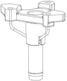
Unpacking Instructions
|
When unpacking the wind sensor, remove the transportation damper that |
|
protects the sensor body. To avoid bending or twisting the array, do not remove |
|
the damper protecting the array until you have installed WMT700. The figure |
|
below shows the damper protecting the array. |
|
|
NOTE |
Remove the transportation damper for the array before you switch on the |
|
power supply. |
|
|
CAUTION |
When handling WMT700, do not rotate, pull, strike, bend, scrape, or |
|
touch the transducers with sharp objects. Any impact on the wind sensor |
|
array damages the device. |
|
|
VAISALA ________________________________________________________________________ 3
QUICK REFERENCE GUIDE _________________________________________________________
Selecting Location for Representative Measurements
Finding a suitable site for WMT700 is important for getting representative measurements. The site should represent the general area of interest. It is recommended that you follow the WMO Guide to Meteorological Instruments and Methods of Observation WMO-No. 8.
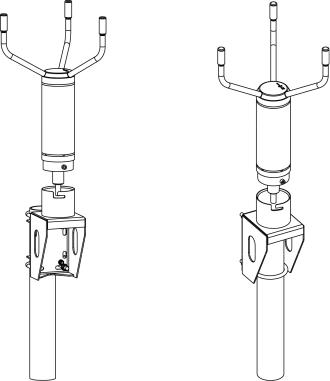
Mounting
When mounting on a vertical pole mast, WMT700 can be placed either on the side or on top of the mast. The figure below shows the mounting options for a vertical mast.
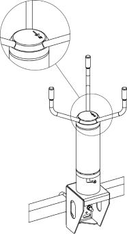
When mounting WMT700 on a cross arm, the wind sensor can be placed with the array facing up or down. The following figure shows WMT700 installed with the array facing up. If the wind sensor is installed with the array facing down, refer to section Configuration Parameters in the User's Guide.
4 ___________________________________________________________________ M211218EN-B
__________________________________________________________________________ English
Aligning
WMT700 is permanently marked with the letter N and a north arrow. WMT700 needs to be aligned in such a way that this arrow points to the north and the N-S transducers are in line with each other. Misaligning WMT700 causes a wind direction offset error in the measurement results. If mechanical alignment of WMT700 cannot be done, you can correct the wind direction offset error using an offset adjustment command. Refer to section Alignment Tuning in the User's Guide.
Powering
WMT700 can be used with any general power supply of 9 ... 36 V that meets the applicable safety regulations. Connect the heating supply wires to the ground in case heating is not used. The table below lists the power supply requirements.
Heating Option |
Operating |
Heating |
Required |
|
Voltage |
Voltage |
Heating Power |
|
|
|
Supply |
None |
9 … 36 V |
- |
- |
Transducers |
9 … 36 V |
24 / 36 VDC |
40 W |
Transducers and arms |
9 … 36 V |
24 VDC |
200 W |
VAISALA ________________________________________________________________________ 5

QUICK REFERENCE GUIDE _________________________________________________________
Wiring
The figure below shows the pins of the 17-pin M23 Connector.
The table below shows how to connect Cable 2m (227567SP) and Cable 10m (227568SP).
Power Supply |
|
|
|
|
Wire Colors |
Pin |
|
Operating Power Supply |
|
|
|
White |
1 |
||
Operating Power Supply Ground |
|
|
Gray-Pink |
11 |
|||
Heater Power Supply |
|
|
|
Gray |
5 |
||
Heater Power Supply |
|
|
|
Pink |
6 |
||
Heater Power Supply Ground |
|
|
Blue |
7 |
|||
Heater Power Supply Ground |
|
|
Red |
8 |
|||
Enclosure Ground |
|
|
|
Shield |
Shield |
||
Analog Outputs |
|
|
|
|
|
||
Analog Output AOUT2, Wind Direction |
|
Brown |
2 |
||||
Analog Output AOUT1, Wind Speed |
|
|
White-Green |
13 |
|||
Reference Input for AOUT2 (simulated potentiometer) |
White-Gray |
17 |
|||||
Analog Output Ground |
|
|
|
Red-Blue |
12 |
||
COM Port |
|
RS-232 |
RS-422 |
RS-485 |
SDI-12 |
|
|
|
|
RS232Rx |
RxB |
RxB |
- |
Green |
3 |
COM2 |
|
RS232Tx |
TxB |
TxB |
Data |
Yellow |
4 |
|
- |
TxA |
TxA |
- |
Brown-Green |
14 |
|
|
|
||||||
|
|
- |
RxA |
RxA |
- |
White-Yellow |
15 |
COM1 and COM2 Communication Ports Ground |
Violet |
10 |
|||||
COM1 |
|
RS-485, B |
|
|
|
Black |
9 |
(service port) |
|
RS-485, A |
|
|
|
Brown-Yellow |
16 |
6 ___________________________________________________________________ M211218EN-B
__________________________________________________________________________ English
The table below describes the wiring of RS485 Cable 2 m (228259SP) and
RS485 Cable 10 m (228260SP).
Power Supply
Operating Power Supply
Operating Power Supply Ground
Heater Power Supply
Heater Power Supply Ground
Enclosure Ground
COM2
RS485, B
RS485, A Communications Ground
Wire Colors |
Pin |
White |
1 |
Gray-Pink |
11 |
Gray, Green, Pink |
5, 6 |
Blue, Black, Red, Yellow |
7, 8 |
Shield |
Shield |
Brown |
|
3,4 |
|
Red-Blue |
14, 15 |
Violet |
10 |
Operating WMT700
The table below lists the operating commands when the WMT700 protocol is selected.
Command |
Description |
$aMEAS |
Starts wind measurement. The duration of the |
|
measurement is based on the user-configurable |
|
averaging time. |
$aOPEN |
Switches the serial port to the configuration mode. |
$aPOLL,y |
Fetches data from WMT700. |
$aSLEEP |
Switches WMT700 from the normal operating mode to |
|
the low-power mode. |
where
$ |
= |
Fixed text |
a |
= |
WMT700 address. If the value is 0, it refers to any WMT700 |
|
= |
address |
y |
Identification number for the data message format. For a list |
|
|
|
of the data message formats, see WMT700 User's Guide |
|
|
(M211095EN) |
To change the existing parameters, use the configuration commands. For information on the configuration commands, see WMT700 User's Guide (M211095EN).
For information on the available commands when using WS425 or SDI-12 protocols, see WMT700 Technical Reference (M211097EN).
Visit our Internet pages at www.vaisala.com.
VAISALA ________________________________________________________________________ 7

QUICK REFERENCE GUIDE _________________________________________________________
FRANÇAIS
Présentation
Ce Guide de référence rapide contient des informations nécessaires à l’installation du WMT700 avec le kit de montage FIX70.
Vous pouvez télécharger le Manuel de l’utilisateur complet à l’adresse suivante : www.vaisala.com/wmt700.
Instructions de déballage
|
Pour déballer le capteur de vent, retirez l'amortisseur de transport qui protège le |
|
corps du capteur. Pour éviter de plier ou de tordre le réseau d’antennes, ne |
|
retirez pas l'amortisseur de protection de transducteurs à ultrason avant d'avoir |
|
installé le WMT700. La figure ci-dessous représente l'amortisseur de protection |
|
de transducteurs à ultrason. |
|
|
REMARQUE |
Retirez l’amortisseur de protection de transducteurs à ultrason avant de |
|
mettre le capteur sous tension. |
|
|
ATTENTION |
Lorsque vous manipulez le capteur WMT700, évitez de tourner, tirer, |
|
heurter, plier, érafler ou toucher les transducteurs avec des objets pointus. |
|
Le moindre impact sur le positionnement des transducteurs du capteur de |
|
vent peut endommager l'appareil. |
|
|
8 ___________________________________________________________________ M211218EN-B
_________________________________________________________________________ Français
Sélection d’un emplacement pour les mesures représentatives
Pour obtenir des mesures représentatives, il est important de trouver un site adéquat pour le WMT700. Ce site doit être représentatif de l’ensemble de la zone d’intérêt. Nous vous recommandons de suivre le Guide des instruments et des méthodes d'observation météorologiques OMM-N° 8.
Montage
Sur un mât vertical, le WMT700 peut être monté sur le côté ou sur le dessus. La figure ci-dessous représente les options de montage sur un mât vertical.
Si vous montez le WMT700 sur une traverse, le capteur de vent peut être placé avec les transducteurs vers le haut ou vers le bas. La figure suivante montre le WMT700 installé avec les transducteurs orientés vers le haut. Si le capteur de vent est installé avec les transducteurs orientés vers le bas, reportez-vous à la section Paramètres de configuration dans le Manuel de l’utilisateur.
VAISALA ________________________________________________________________________ 9
Loading...