


CL31
Table of contents
 Loading...
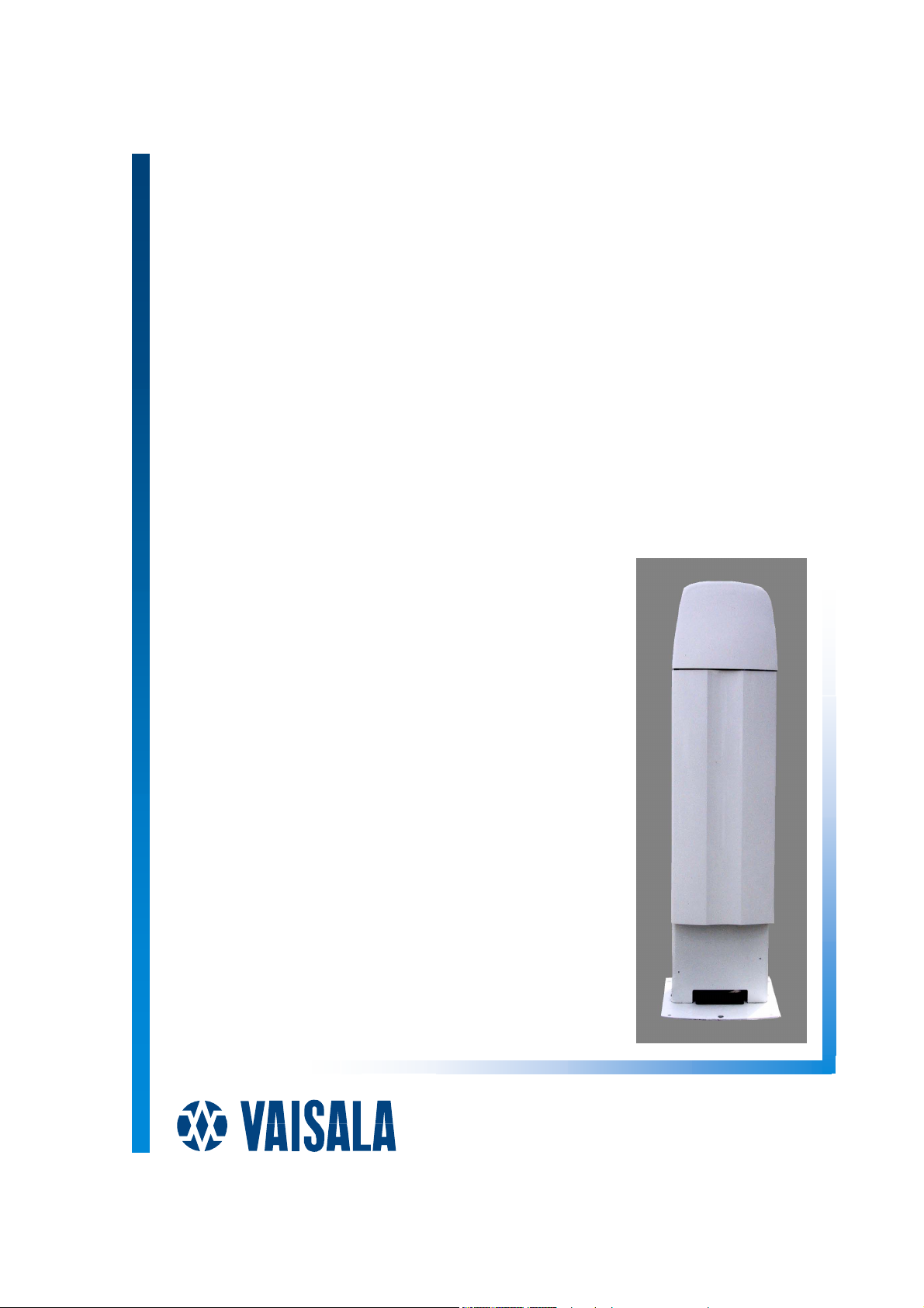
Vaisala Ceilometer
CL31
USER'S GUIDE
M210482EN-B
October 2004

PUBLISHED BY
Vaisala Oyj Phone (int.): +358 9 8949 1
P.O. Box 26 Fax: +358 9 8949 2227
FIN-00421 Helsinki
Finland
Visit our Internet pages at http://www.vaisala.com/
© Vaisala 2004
No part of this manual may be reproduced in any form or by any means,
electronic or mechanical (including photocopying), nor may its contents be
communicated to a third party without prior written permission of the copyright
holder.
The contents are subject to change without prior notice.
Please observe that this manual does not create any legally binding obligations for
Vaisala towards the customer or end user. All legally binding commitments and
agreements are included exclusively in the applicable supply contract or
Conditions of Sale.

________________________________________________________________________________
Table of Contents
CHAPTER 1
GENERAL INFORMATION............................................................................7
About This Manual ................................................................... 7
Contents of This Manual ....................................................... 7
Related Manuals ................................................................... 8
Feedback............................................................................... 8
Safety......................................................................................... 8
General Safety Considerations ............................................. 8
Product Related Safety Precautions ..................................... 9
Laser Safety ........................................................................ 10
ESD Protection.................................................................... 11
Recycling ................................................................................ 12
Warranty..................................................................................12
CHAPTER 2
PRODUCT OVERVIEW................................................................................ 13
Introduction to Vaisala Ceilometer CL31............................. 13
Product Nomenclature........................................................... 15
CHAPTER 3
INSTALLATION............................................................................................ 19
Installation Procedure............................................................ 19
Unloading and Unpacking Instructions ............................... 19
Preparing a Concrete Foundation....................................... 20
Mounting the Ceilometer CL31 ...........................................22
Connecting the External Cables ......................................... 25
Data Line Connection.......................................................... 26
Grounding............................................................................ 28
Maintenance Terminal Connection .....................................29
Setting up Maintenance Terminal Connection............... 29
Operation of Maintenance Terminal Connection ........... 29
Using the Tilt Feature.......................................................... 29
Mobile Operation Aspects ................................................... 30
Startup..................................................................................... 31
Startup Procedure ............................................................... 31
Settings for Normal Operation ............................................ 34
Factory Settings of User Programmable Parameters ......... 35
CHAPTER 4
OPERATION................................................................................................. 37
Operation Modes .................................................................... 37
Serial Lines - Open and Closed Port .................................... 37
VAISALA ________________________________________________________________________ 3

User's Guide ______________________________________________________________________
User Commands .....................................................................39
Data Messages........................................................................ 44
CL31 Data Messages No. 1 and 2 ......................................45
CRC16 Checksum..........................................................51
CL31 Status Message .........................................................52
CT12K Messages ................................................................ 55
CT12K Digital Message No. 2........................................ 55
CT12K Digital Message No. 3........................................ 59
CT25K Data Messages .......................................................60
CT25K Data Message No. 1 ..........................................60
CT25K Data Message No. 6 ..........................................62
CT25KAM Data Messages.................................................. 64
CT25KAM Data Message No. 60...................................64
CT25KAM Data Message No. 61...................................64
LD40 Standard Telegram ....................................................64
Telegram Structure Remarks .........................................66
Failure and Warning Messages .....................................66
Checksum Calculation....................................................69
Manual Message .................................................................70
Polling Mode ...........................................................................70
CHAPTER 5
FUNCTIONAL DESCRIPTION .....................................................................73
Theory of Operation ...............................................................73
Basic Principle of Operation ................................................ 73
Practical Measurement Signal.............................................74
Noise Cancellation ..............................................................74
Return Signal Strength ........................................................75
Height Normalization ...........................................................75
Backscatter Coefficient........................................................ 75
Extinction Normalization and Vertical Visibility....................77
CHAPTER 6
MAINTENANCE............................................................................................79
Periodic Maintenance............................................................. 79
Alarms and Warnings ..........................................................79
Window Cleaning.................................................................80
Calibration ......................................................................80
Checking the Door Gasket .................................................. 81
Battery Check ...................................................................... 81
Storage ................................................................................82
CHAPTER 7
TROUBLESHOOTING..................................................................................83
Accessing the Diagnostic Information.................................84
Equipment ...........................................................................84
Troubleshooting Instructions ............................................... 84
Warning and Alarm Messages ..............................................86
Technical Support .................................................................. 90
Vaisala Service Centers ......................................................... 90
4 ___________________________________________________________________ M210482EN-B

________________________________________________________________________________
CHAPTER 8
REPAIR ........................................................................................................ 91
Replacing Window Assembly CLW311................................ 91
Replacing Ceilometer Laser Transmitter CLT311............... 93
Replacing Ceilometer Receiver CLR311.............................. 94
Replacing Ceilometer Engine Board CLE311.................... 100
Replacing No-break Battery 4592....................................... 101
Replacing AC Power CLP311.............................................. 102
Replacing Window Blower CLB311-115 / CLB 311-230.... 104
Replacing Ceilometer Optics CLO311................................ 105
Replacing Internal Heater CLH311-115 / CLH311-230 ......107
Replacing Internal Cable Set............................................... 109
Replacing Laser Monitor Board CLM311........................... 113
Replacing Modem Module DMX501 (Optional).................. 115
CHAPTER 9
TECHNICAL DATA .................................................................................... 117
Specifications ....................................................................... 117
Mechanical Specifications................................................. 117
External Connector J1 - Window Conditioner ................... 118
External Connector J2 - Power Input ................................ 118
Output Interface ................................................................ 118
External Connector J3 - Data Line............................... 119
External Connector J4 - Maintenance Line.................. 120
Modem Module DMX501 ..................................................121
Transmitter Specifications................................................. 121
Receiver Specifications..................................................... 122
Optical System Specifications........................................... 122
Performance Specifications .............................................. 122
Environmental Conditions Specifications.......................... 123
INDEX ......................................................................................................... 125
List of Figures
Figure 1 Vaisala Ceilometer CL31.......................................................... 14
Figure 2 Ceilometer CL31 Main Parts .................................................... 16
Figure 3 Measurement Unit Handle ....................................................... 20
Figure 4 Foundation Construction .......................................................... 21
Figure 5 Removing and Attaching the Measurement Unit ..................... 23
Figure 6 Mounting the Shield.................................................................. 24
Figure 7 External Connectors (Bottom View) ......................................... 25
Figure 8 Data Line Modem Connection.................................................. 26
Figure 9 Data Line RS-485 Connection ................................................. 27
Figure 10 Data Line RS-232 Connection ................................................. 28
Figure 11 Subassembly Interconnections ................................................ 32
Figure 12 CL31 Switches ......................................................................... 33
Figure 13 Ceilometer Engine Board CLE311 ........................................... 34
Figure 14 Operation Modes...................................................................... 37
Figure 15 Open and Closed Port.............................................................. 39
Figure 16 Typical Measurement Signal.................................................... 74
VAISALA ________________________________________________________________________ 5

User's Guide ______________________________________________________________________
Figure 17 CL31 ......................................................................................... 96
Figure 18 Main Components of Ceilometer CL31 .................................... 98
Figure 19 Ceilometer Engine Board CLE311 ........................................... 99
Figure 20 Grounding Wires of the Internal Cable Set (top view)............ 110
Figure 21 Internal Heater Wiring and Connector at the Left of the Optics
Frame .....................................................................................111
Figure 22 Optics Frame with Cable Set..................................................112
Figure 23 Connecting Mains Filters to the Cable Set .............................112
Figure 24 DMX501..................................................................................116
Figure 25 Pin Connections of Connector J4 ........................................... 120
List of Tables
Table 1 Related Manuals......................................................................... 8
Table 2 Vaisala Ceilometer CL31 Main Parts .......................................15
Table 3 Vaisala Ceilometer CL31 Optional Parts..................................15
Table 4 Factory Defaults of User-Programmable Parameters ..............35
Table 5 User Level Commands .............................................................40
Table 6 Advanced Level Commands.....................................................43
Table 7 Messages with 10 m Resolution (Standard Mode)...................46
Table 8 Messages with 5 m Resolution (High Resolution)....................46
Table 9 Error Group Definition...............................................................67
Table 10 Error Group 1 (Byte 83) ............................................................67
Table 11 Error Group 2 (Byte 84) ............................................................67
Table 12 Error Group 3 (Byte 85) ............................................................67
Table 13 Error Group 4 (Byte 86) ............................................................68
Table 14 Error Group 5 (Byte 87) ............................................................68
Table 15 Error Group 6 (Byte 88) ............................................................ 68
Table 16 Error Group 7 (Byte 89) ............................................................68
Table 17 Command Telegram Description 'Polling Request' .................. 71
Table 18 Warnings...................................................................................86
Table 19 Alarms.......................................................................................88
Table 20 Miscellaneous Problems...........................................................89
Table 21 Ceilometer CL31 Mechanical Specifications.......................... 117
Table 22 Window Conditioner ...............................................................118
Table 23 Power Input.............................................................................118
Table 24 Data Line ................................................................................119
Table 25 Maintenance Line ................................................................... 120
Table 26 Modem Module DMX501 Specifications ................................121
Table 27 Transmitter Specifications ......................................................121
Table 28 Receiver Specifications ..........................................................122
Table 29 Optical System Specifications ................................................122
Table 30 Performance Specifications....................................................122
Table 31 Environmental Conditions Specifications ...............................123
6 ___________________________________________________________________ M210482EN-B

Chapter 1 ________________________________________________________ General Information
CHAPTER 1
GENERAL INFORMATION
This chapter provides general notes for the product.
About This Manual
This manual provides information for installing, operating, and
maintaining Vaisala Ceilometer CL31.
Contents of This Manual
This manual consists of the following chapters:
- Chapter 1, General Information, provides general notes for the
product.
- Chapter 2, Product Overview, introduces the features, advantages,
and the product nomenclature.
- Chapter 3, Installation, provides you with information that is
intended to help you install this product.
- Chapter 4, Operation, contains information that is needed to
operate this product.
- Chapter 5, Functional Description, describes the functionality of
the product.
- Chapter 6, Maintenance, provides information that is needed in the
basic maintenance of the product.
- Chapter 7, Troubleshooting, describes common problems, their
probable causes and remedies, and gives the contact information.
- Chapter 8, Repair, explains how to remove and replace different
parts of Vaisala Ceilometer CL31.
VAISALA ________________________________________________________________________ 7
User's Guide ______________________________________________________________________
- Chapter 9, Technical Data, provides the technical data of the
product.
- INDEX
Related Manuals
Table 1 Related Manuals
Manual Code Manual Name
M210310EN-A Termination Box User's Guide
Feedback
Vaisala Customer Documentation Team welcomes your comments
and suggestions on the quality and usefulness of this publication. If
you find errors or have other suggestions for improvement, please
indicate the chapter, section, and page number. You can send
comments to us by e-mail: manuals@vaisala.com
Safety
WARNING
CAUTION
General Safety Considerations
Throughout the manual, important safety considerations are
highlighted as follows:
Warning alerts you to a serious hazard. If you do not read and follow
instructions very carefully at this point, there is a risk of injury or
even death.
Caution warns you of a potential hazard. If you do not read and
follow instructions carefully at this point, the product could be
damaged or important data could be lost.
NOTE
8 ___________________________________________________________________ M210482EN-B
Note highlights important information on using the product.

Chapter 1 ________________________________________________________ General Information
WARNING
WARNING
Failure to comply with these precautions or with specific warnings
elsewhere in this manual violates safety standards of design,
manufacture, and intended use of the instrument. Vaisala Oyj
assumes no liability for the customer's failure to comply with these
requirements.
Product Related Safety Precautions
Vaisala Ceilometer CL31 delivered to you has been tested for safety
and approved as shipped from the factory. The following safety
precautions must be observed during all phases of operation, service,
and repair of this instrument:
To minimize shock hazard, the instrument chassis and cabinet must
be connected to an electrical ground. The instrument is equipped
with a three-conductor AC power connector. The power cable must
either be plugged into an approved three-contact electrical outlet or
the instrument must be carefully grounded to a low-resistance safety
ground.
WARNING
WARNING
WARNING
Do not operate the instrument in the presence of flammable gases or
fumes. Operation of any electrical instrument in such an environment
constitutes a definite safety hazard.
Do not attempt internal service or adjustment unless another person,
capable of rendering first aid and resuscitation, is present.
Because of the danger of introducing additional hazards, do not
install substitute parts or perform any unauthorized modification to
the instrument. Return the instrument to a Vaisala office or
authorized Depot for service and repair to ensure that safety features
are maintained.
VAISALA ________________________________________________________________________ 9
User's Guide ______________________________________________________________________
WARNING
WARNING
Operating personnel must not remove instrument covers. Component
replacement and internal adjustments must be made by qualified
maintenance personnel. Do not replace components with the power
cable connected. Under certain conditions, dangerous voltages may
exist even with the power cable removed. To avoid injuries, always
disconnect power and discharge circuits before touching them.
High voltage will be present when the Laser Transmitter CLT311 or
Receiver CLR311 covers are removed and they are connected to a
powered unit. High voltage is present in AC Power Unit CLP311,
Internal Heater CLH311, Ceilometer Engine Board CLE311, and the
Window Blower CLB311 at the top of the Shield.
Laser Transmitter CLT311, Receiver CLR311, and AC Power Unit
CLP311 are equipped with the following warning label:
WARNING! HIGH VOLTAGE INSIDE THIS
ENCLOSURE
Internal Heater CLH311 can be hot and is equipped with the following
warning labels:
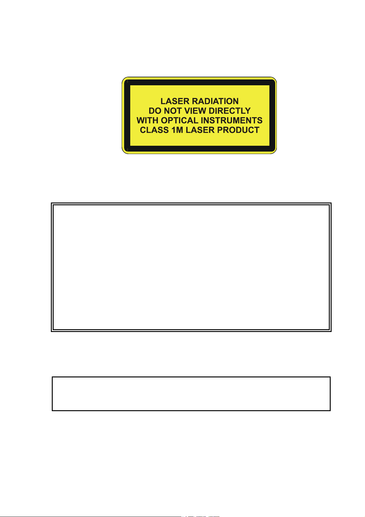
Laser Safety
Vaisala Ceilometer CL31 is classified as a Class 1M laser device in
accordance with International Standard IEC/EN 60 825-1. Complies
with 21 CFR 1040.10 and 1040.11 except for the deviations pursuant
to the Laser Notice No. 50, dated July 26, 2001. This means that
when CL31 is installed in a field environment with instrument covers
on and pointed vertically or near-vertically, it poses no established
biological hazard to humans.
10 __________________________________________________________________ M210482EN-B
Chapter 1 ________________________________________________________ General Information
The device is equipped with the following label:
Ceilometer CL31 is intended for operation in an area restricted from
public access, and to be pointed vertically or near-vertically. The
following precautions must be followed during the service and
maintenance of the instrument:
WARNING
CAUTION
Never look directly into the Ceilometer Transmitter or Ceilometer
Optics with magnifying optics (such as glasses, binoculars, and
telescopes). Never remove the Ceilometer Transmitter from its
normal position without first switching off both the line and the
battery power and detaching the trasnmitter ribbon cable from the
Ceilometer Engine Board.
When operating, avoid looking at the ceilometer unit from the beam
direction. When tilting the unit, make sure that it is not being viewed
from the beam direction with magnifying optics.
Only trained personnel should perform maintenance functions.
Access to the work area by unauthorized persons during service
operations must be prevented.
ESD Protection
The equipment contains parts and assemblies sensitive to damage by
Electrostatic Discharge (ESD). Use ESD precautionary procedures
when touching, removing or inserting.
Electrostatic Discharge (ESD) can cause immediate or latent damage
to electronic circuits. Vaisala products are adequately protected
against ESD for their intended use. However, it is possible to damage
VAISALA _______________________________________________________________________ 11
User's Guide ______________________________________________________________________
the product by delivering electrostatic discharges when touching,
removing, or inserting any objects inside the equipment housing.
To make sure you are not delivering high static voltages yourself:
- Handle ESD sensitive components on a properly grounded and
protected ESD workbench. When this is not possible, ground
yourself to the equipment chassis before touching the boards.
Ground yourself with a wrist strap and a resistive connection cord.
When neither of the above is possible, touch a conductive part of
the equipment chassis with your other hand before touching the
boards.
- Always hold the boards by the edges and avoid touching the
component contacts.
Recycling
Warranty
Recycle all applicable material.
Dispose of batteries and the unit according to statutory regulations.
Do not dispose of with regular household refuse.
For certain products Vaisala normally gives a limited one-year
warranty. Please observe that any such warranty may not be valid in
case of damage due to normal wear and tear, exceptional operating
conditions, negligent handling or installation, or unauthorized
modifications. Please see the applicable supply contract or Conditions
of Sale for details of the warranty for each product.
12 __________________________________________________________________ M210482EN-B

Chapter 2 __________________________________________________________ Product Overview
CHAPTER 2
PRODUCT OVERVIEW
This chapter introduces the features, advantages, and the product
nomenclature.
Introduction to Vaisala Ceilometer CL31
Vaisala Ceilometer CL31 measures cloud height and vertical
visibility. The small and lightweight measurement unit suits well for
mobile operation.
Ceilometer CL31 employs pulsed diode laser LIDAR technology
(LIDAR = Light detection and ranging), where short, powerful laser
pulses are sent out in a vertical or near-vertical direction. The
reflection of light - backscatter - caused by haze, fog, mist, virga,
precipitation, and clouds is measured as the laser pulses traverse the
sky. The resulting backscatter profile, that is, the signal strength
versus the height, is stored and processed and the cloud bases are
detected. Knowing the speed of light, the time delay between the
launch of the laser pulse and the detection of the backscatter signal
indicates the cloud base height.
Ceilometer CL31 is able to detect three cloud layers simultaneously. If
the could base is obscured due to precipitation or ground-based fog,
CL31 reports vertical visibility. No adjustments in the field are
needed. The embedded software includes several service and
maintenance functions and gives continuous status information from
internal monitoring. The software is designed to give the full
backscatter profile.
To make Ceilometer CL31 easier to use and to ease the transfer from
old ceilometer versions to this new one, CL31 includes data messages
used in CT12K, CT25K, CT25KAM, and LD40.
VAISALA _______________________________________________________________________ 13
User's Guide ______________________________________________________________________
0406-052
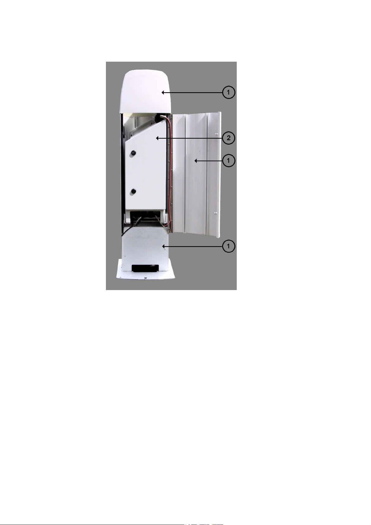
Figure 1 Vaisala Ceilometer CL31
The following numbers refer to Figure 1 above:
1 = Shield
2 = Measurement Unit
14 __________________________________________________________________ M210482EN-B
Chapter 2 __________________________________________________________ Product Overview
Product Nomenclature
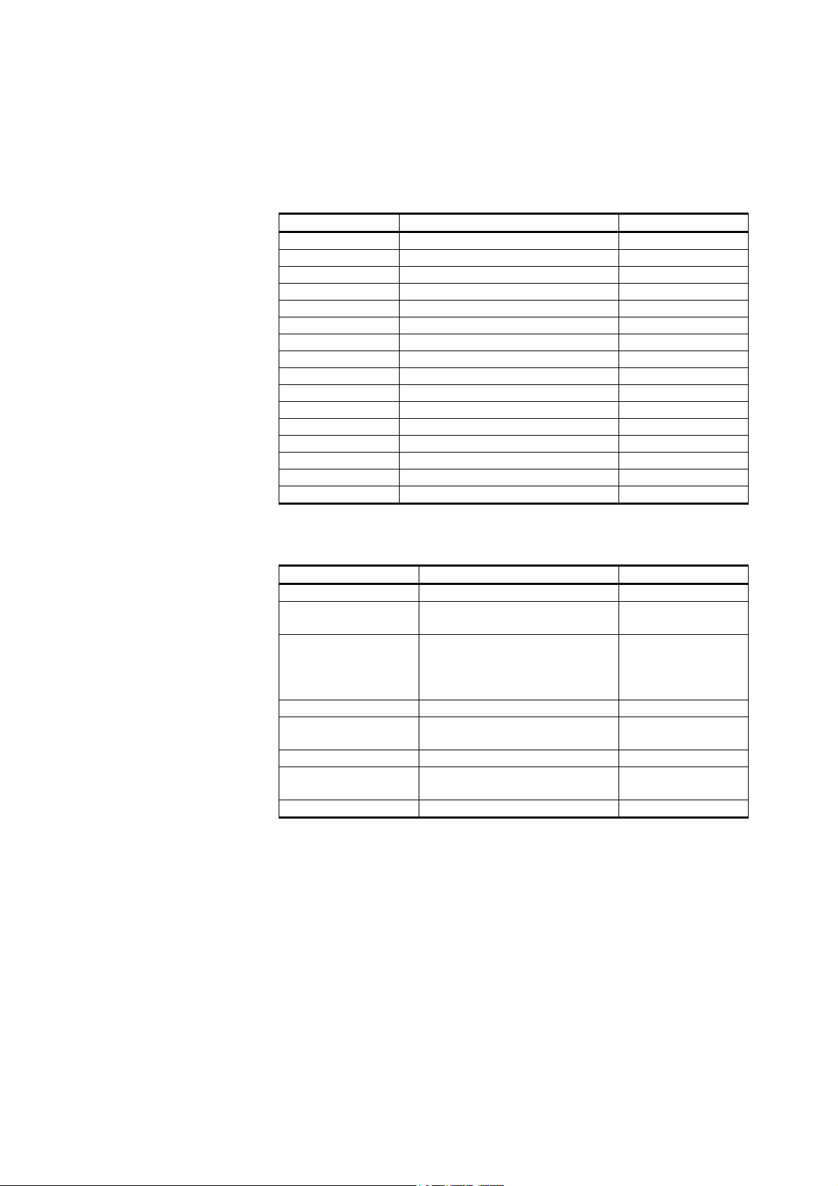
Table 2 Vaisala Ceilometer CL31 Main Parts
Code Common Name Description
CLO311 Optics Unit
CLW311 Window Assembly Spare part
CLT311SP Ceilometer Transmitter Spare part
CLR311 Ceilometer Receiver Spare part
CLM311 Laser Monitor Board Spare part
CLE311SP Ceilometer Engine Board Spare part
CLP311 AC Power Spare part
4592 No-break Battery Spare part
CLH311-115SP Inside Heater (100 ... 115 VAC) Spare part
CLH311-230SP Inside Heater (220 ... 240 VAC) Spare part
CLB311-115SP Window Blower (100 ... 115 VAC) Spare part
CLB311-230SP Window Blower (220 ... 240 VAC) Spare part
CT3839SP Power cable (230 V) Spare part
CT35324SP Power cable (115 V) Spare part
CT3838 Data cable Spare part
DRW217429 Coaxial Cable Spare part
Table 3 Vaisala Ceilometer CL31 Optional Parts
Code Common Name Description
DMX501 Modem Module Spare part
CLRADIOKIT Radio Modem Installation Kit Excl. radio modem
and antenna
TERMBOX-1200 Termination box, Mains and
signal
QMZ101 Maintenance cable
PSION Maintenance terminal
(palmtop computer)
CLTERMHOOD Optical Termination Hood
CT35022 Shock Absorber For ship
HMP50 UAB1A1A Internal Humidity Transmitter
For extended
surge and
overvoltage
protection
installations
The complete delivery also includes mating cables with connectors for
power and communication, installation hardware, a key for the
measurement unit door, and this CL31 User's Guide.
VAISALA _______________________________________________________________________ 15
User's Guide ______________________________________________________________________
0311-057
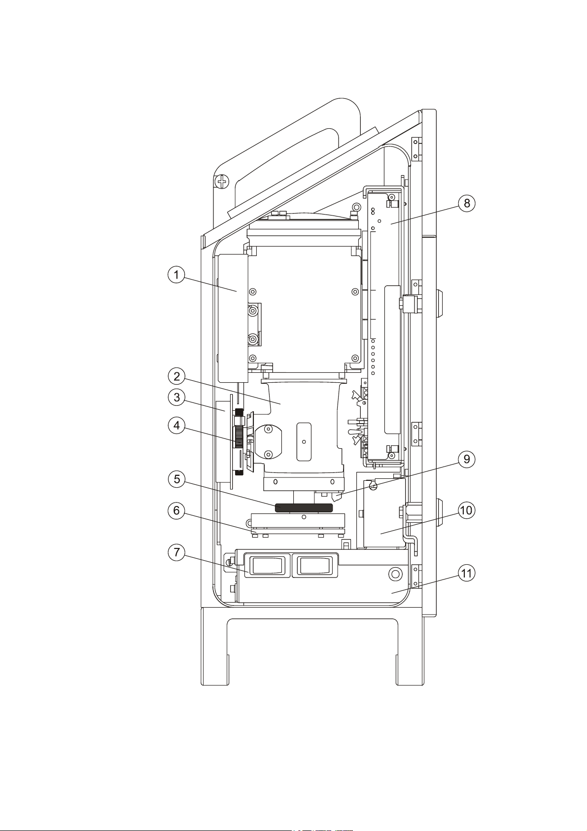
Figure 2 Ceilometer CL31 Main Parts
16 __________________________________________________________________ M210482EN-B

Chapter 2 __________________________________________________________ Product Overview
The following numbers refer to Figure 2 on page 16:
1 = Internal heater CLH311
2 = CLO311 Optics unit
3 = Ceilometer Receiver CLR311
4 = Receiver ring
5 = Transmitter ring
6 = Ceilometer Transmitter CLT311
7 = F1 Main circuit breaker
F2 Window blower circuit breaker
8 = Ceilometer Engine Board CLE311
9 = Laser Monitor Board CLM311
10 = Battery 4592
11 = AC Power CLP311
12 = Battery switch
VAISALA _______________________________________________________________________ 17

User's Guide ______________________________________________________________________
This page intentionally left blank.
18 __________________________________________________________________ M210482EN-B

Chapter 3 _______________________________________________________________ Installation
CHAPTER 3
INSTALLATION
This chapter provides you with information that is intended to help
you install this product.
Installation Procedure
This section describes the installation procedure of Vaisala Ceilometer
CL31.
Unloading and Unpacking Instructions
CL31 is shipped in one container that contains the shield, the
measurement unit inside the shield, and all the equipment, accessories,
and documentation needed for carrying out the installation. Store the
original packaging for possible later transport need.
For opening, the package should be placed on a flat surface with the
indicated top side up. You should open the container from the top side
and carefully remove the ceilometer and all the other equipment.
- Use proper gloves for protection against sharp edges, etc.
- Avoid touching the window or lens surfaces, unless you plan to
clean them properly afterwards.
- Keep the integral protective caps on the unused external connectors
(J4 Maintenance line).
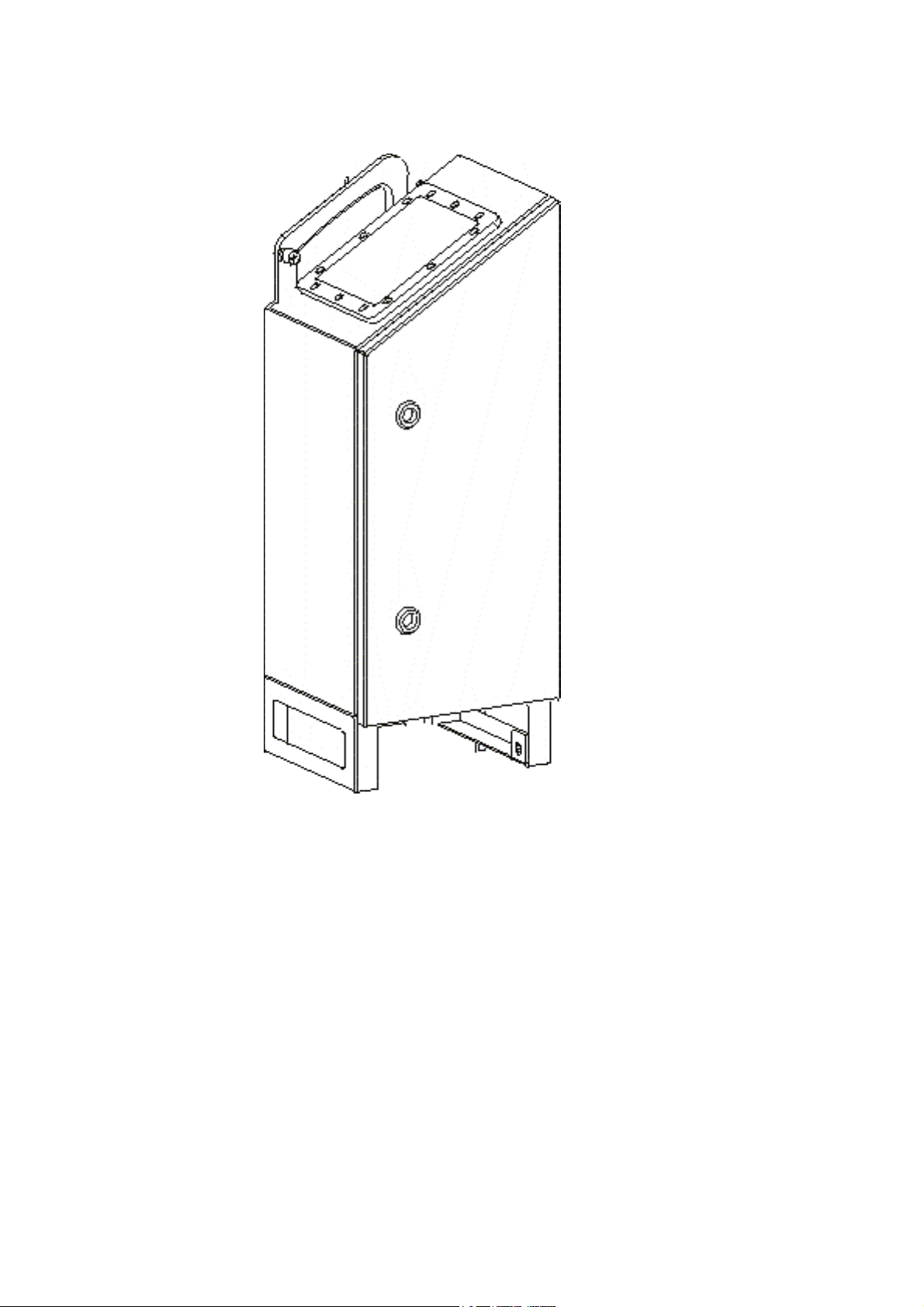
- Use the measurement unit handle for lifting and carrying the
measurement unit. See Figure 3 on page 20.
VAISALA _______________________________________________________________________ 19
User's Guide ______________________________________________________________________
0311-054
Figure 3 Measurement Unit Handle
If mishandling occurs during transit or installation, the instrument
should be returned to a Vaisala office or authorized Depot for
inspection.
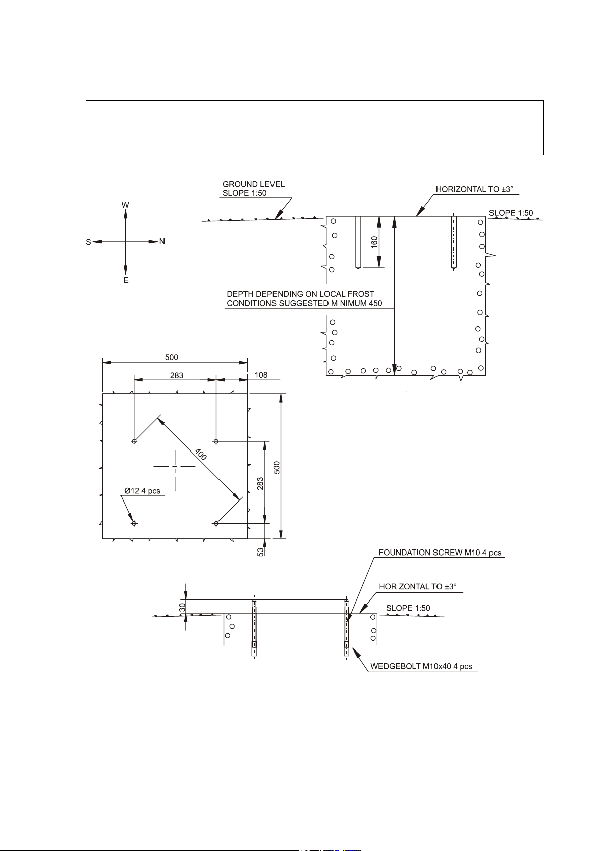
Preparing a Concrete Foundation
The standard foundation for the CL31 ground installation is a concrete
foundation. The minimum dimensions suggested are presented in
Figure 4 on page 21. Mounting hardware is included with the delivery.
20 __________________________________________________________________ M210482EN-B
Chapter 3 _______________________________________________________________ Installation
NOTE
In case CL31 is used to replace another ceilometer (CT25K, CT12K,
LD40, LD25, or LD12) the existing foundation and foundation
screws can be used.
9412-027
Figure 4 Foundation Construction
VAISALA _______________________________________________________________________ 21

User's Guide ______________________________________________________________________
There are two alternative ways to create a concrete foundation for
Ceilometer CL31. You can either cast a new concrete foundation or
use an existing one.
NOTE
If the tilt feature will be used (see section Using the Tilt Feature on
page 29), observe this in the layout of the foundation screws and
shield placement.
Creating a New Concrete Foundation
1. Fasten the M10 × 40 wedge bolts to the lower ends of the
foundation screws (4 each).
2. Fix a drilling template to the upper ends of the foundation
screws with nuts.
3. Place the template with the attached foundation screws into the
hole in such a way that approximately 30 mm (1.25 inches) of
the foundation screw threads stand above the surface.
4. Pour in the concrete and finish the foundation.
Using an Existing Foundation
1. Drill four holes with a diameter of 12 mm and a depth of
165 mm (0.5 × 6.5 inches) into the concrete.
2. Fasten the M10 × 40 wedge bolts to the lower ends of the
foundation screws (4 each).
3. Place the wedge bolt and foundation screw combinations into
the holes, with the wedge bolts down, and hammer the
protruding threads down.
4. Tighten the foundation screws a few turns to attach the wedge
bolts to the hole walls.
Mounting the Ceilometer CL31
Ceilometer CL31 is delivered with the measurement unit attached to
the shield. If two people are handling the installation, the shield can be
mounted with the measurement unit attached. It is, however,
recommended that you first remove the measurement unit, mount the
shield, and then reattach the measurement unit to the shield.
22 __________________________________________________________________ M210482EN-B
Chapter 3 _______________________________________________________________ Installation
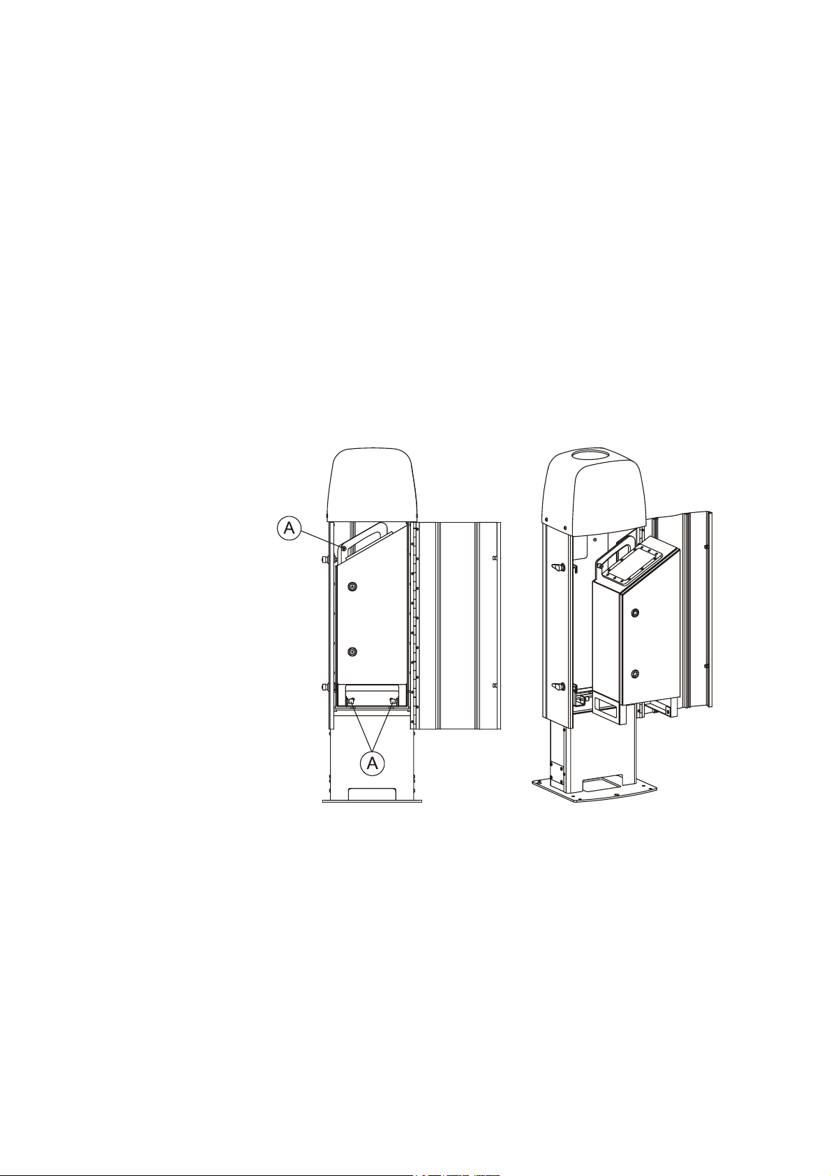
To mount Ceilometer CL31, proceed as follows:
1. Remove the measurement unit from the shield. To do this,
loosen the three attachment screws (marked A in Figure 5
below), disconnect the blower cable from connector J1 (see
Figure 7 on page 25), and pull out the unit.
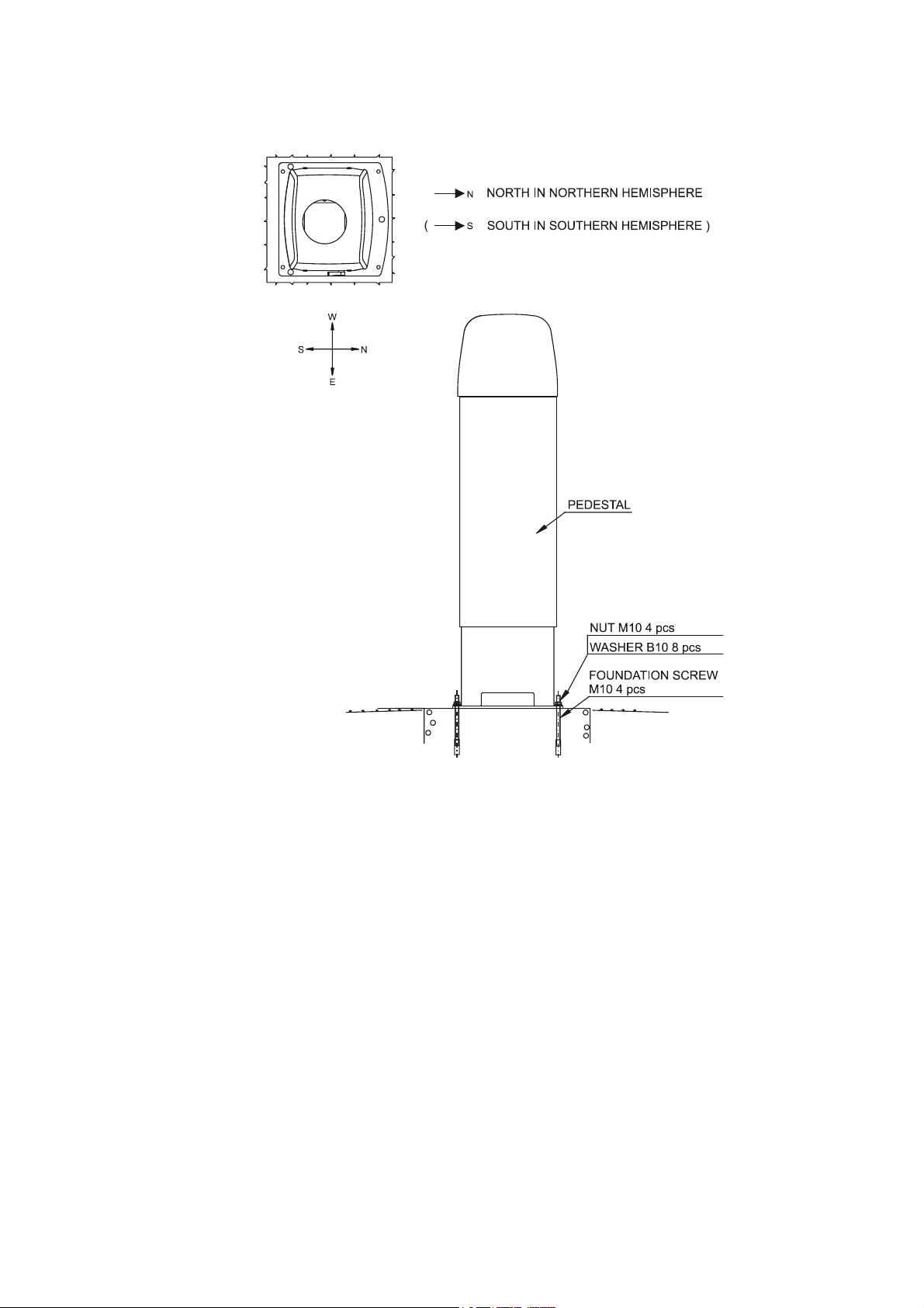
2. Place the shield on the foundation in such a way that the door
faces North in the Northern hemisphere and South in the
Southern hemisphere. Refer to Figure 6 on page 24.
3. Place the flat washers on the foundation screws and fix the nuts.
Refer to Figure 6 on page 24.
4. Place the measurement unit inside the shield, connect the blower
cable to connector J1, and tighten the three attachment screws
(marked A in Figure 5 below).
0311-055
Figure 5 Removing and Attaching the Measurement Unit
VAISALA _______________________________________________________________________ 23
User's Guide ______________________________________________________________________
0311-056
Figure 6 Mounting the Shield
24 __________________________________________________________________ M210482EN-B

Chapter 3 _______________________________________________________________ Installation
Connecting the External Cables
All external connectors to the measurement unit are located at the
bottom front edge as seen from the door direction. Figure 7 below
shows the external connectors J1, J2, J3, and J4.
0306-006
Figure 7 External Connectors (Bottom View)
The window blower mounted into the shield is connected to connector
J1. Line power input is connected to connector J2. Remote
communication is normally connected to connector J3. A local
maintenance terminal, a laptop or a palmtop for example, can be
connected to connector J4. A protective cap is included for covering
J4 when it is not used.
External mating connectors with 2 m (7 ft) cable are included for J2
and for J3. The power plug of the J2 cable can be cut when the unit is
permanently installed at the final site.
VAISALA _______________________________________________________________________ 25

User's Guide ______________________________________________________________________
The wire connections and cable glands of the optional Termination
Box are presented in the Termination Box User's Guide (refer to
section Related Manuals on page 8).
NOTE
When the permanent line power installation is made, the maximum
size of the fuse protecting the power line is 10 A.
Data Line Connection
Vaisala Ceilometer CL31 offers three possible options for the data line
connection. These options are presented in the following figures.
0311-060
Figure 8 Data Line Modem Connection
26 __________________________________________________________________ M210482EN-B

Chapter 3 _______________________________________________________________ Installation
Default Settings for the Data Line Modem Connection
Modem mode V.22bis
Bit rate 2400
Data bits 8
Stop bits 1
Parity None
0311-061
Figure 9 Data Line RS-485 Connection
Default Settings for the Data Line RS-485 Connection
Bit rate 19200
Data bits 8
Stop bits 1
Parity None
VAISALA _______________________________________________________________________ 27
User's Guide ______________________________________________________________________
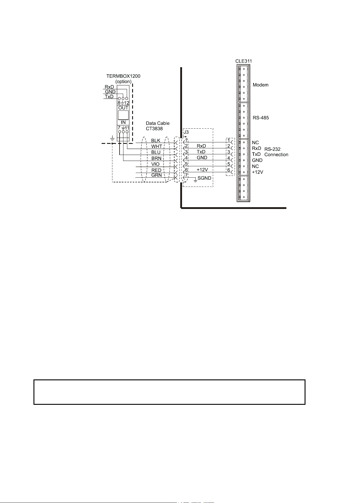
0311-062
CAUTION
Figure 10 Data Line RS-232 Connection
Default Settings for the Data Line RS-232 Connection
Bit rate 19200
Data bits 8
Stop bits 1
Parity None
Handshake None
Grounding
The power supply connector J2 provides a standard protective ground
for the instrument chassis.
CL31 is equipped with a separate grounding screw for external
grounding at the bottom of the shield.
Connection to a solid earth ground at the installation site is
mandatory for adequate lightning and transient protection.
28 __________________________________________________________________ M210482EN-B

Chapter 3 _______________________________________________________________ Installation
Maintenance Terminal Connection
Any terminal or PC with a serial interface and a terminal emulation
program can be used for operation and maintenance of Ceilometer
CL31. The maintenance terminal connection is established with the
QMZ101 maintenance cable, which connects the RS-232 port of the
PC to the maintenance port of the ceilometer.
A standard maintenance terminal option includes a PSION Palmtop
Computer and its Technical Manuals.
Setting up Maintenance Terminal Connection
1. Connect the RS cable to the ceilometer maintenance port
(connector J4) and the terminal computer.
2. Set the following settings for the terminal:
Bit rate 9600
Data bits 8
Stop bits 1
Parity None
Handshake None
Operation of Maintenance Terminal Connection
To operate the connection, do the following:
1. Turn the power on in CL31.
2. Open the CL31 maintenance with the open command.
3. The prompt CEILO > appears. For details, see Chapter 5,
Functional Description, on page 73.
Using the Tilt Feature
Ceilometer CL31 is designed to allow operation in a tilted direction.
The built-in tilt angle sensor detects the tilt angle, that is, the deviation
from vertical. The tilt feature allows three tilt angles: vertical, 12
degrees with the measurement unit door upwards, and 12 degrees with
the measurement unit door downwards. The cosine of the tilt angle is
used for an automatic correction of the detected cloud base height,
which enables accurate cloud base measurements also in a tilted
direction.
VAISALA _______________________________________________________________________ 29
User's Guide ______________________________________________________________________
The tilt feature provides the following advantages:
- Protection in heavy weather conditions:
Using a tilt angle of 12 degrees protects the measurement unit
window from precipitation, thus enhancing the performance in
heavy weather conditions.
- Precision in aircraft approach detection:
The beam can be directed towards a direction that better represents
the approach of an aircraft than the straight vertical. This is useful,
for example, for helicopter approaches, and sites where the
ceilometer cannot be located exactly at the desired spot.
WARNING
NOTE
When tilting the unit, make sure that nobody is watching it with
binoculars or other magnifying optics.
To avoid direct sunlight, tilt the unit away from the sun. That is, tilt it
north in the northern hemisphere and south in the southern
hemisphere. Direct insolation exposure will not damage the unit but
will cause alarms and temporarily invalidate the data
As these advantages may be contradictory or cannot be realized
simultaneously, the user must decide the direction of the final
installation.
Mobile Operation Aspects
The small and lightweight measurement unit of Ceilometer CL31 is
also suitable for mobile operation. It has a built-in 12 V battery, which
enables operation without external power supply for about an hour in
normal room temperature.
NOTE
30 __________________________________________________________________ M210482EN-B
For switching the CL31 power fully off, also turn off the battery
switch in addition to the line power switch. Having the unit on with
the battery supply will only drain the battery.
Loading...