


 Loading...
User’s Guide
www.vaisala.com
Vaisala CARBOCAP® Carbon Dioxide
Transmitter Series
GMW20
M210196EN-B
User’s Guide_____________________________________________________ GMW20

User’s Guide_____________________________________________________ GMW20
Table of Contents |
|
Basics of the GMW20 Series ................................................ |
2 |
Mounting...................................................................................... |
2 |
Electrical Connections ............................................................ |
4 |
Power Supply Requirements................................................ |
5 |
Technical Data ........................................................................... |
7 |
Relays and Other Accessories ............................................. |
8 |
Dimensions (in Millimeters)................................................... |
9 |
1

User’s Guide_____________________________________________________ GMW20
Basics of the GMW20
Series
Vaisala’s GMW20 series transmitters use silicon based CARBOCAP sensor with excellent stability and reliability properties. The series consist of the following transmitter types:
GMW21 and display version GMW21D |
(80x108.5x35) mm |
GMW22 and display version GMW22D |
(80x80x35) mm |
The GMW20 series transmitter is calibrated as shipped from the factory. In benign environments the recommended calibration interval is five years. In case adjustment is needed, contact Vaisala Service or local Vaisala representative.
The reading of the GMW20 can be checked and adjusted with the serial com adapter 19040GM and the calibration software available from www.vaisala.com. The checking in the field can also be done with calibration gas and a multimeter.
Mounting
1.The GMW20 is shipped ready for installation onto a standard wallbox or onto a surface mounting.
2.Drill a hole in the surface where the transmitter will be mounted , then pull the wiring through the drilled hole.
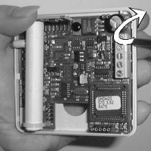
3.Open the transmitter cover by pushing forward and turning a screwdriver head in the slot located at the bottom between the cover and the back plate.
4.Remove the printed circuit board (PCB) by pressing upwards with a screwdriver (see Figure 1 on page 3).
2
User’s Guide_____________________________________________________ GMW20
Figure 1 Cable routing
5.Thread the power wires and output signal wire through the center hole of the back plate. In case of surface wiring, make (e.g.with a pliers) cut-out by removing the attenuated part at lower edge of the back plate.
6.Center the hole in the base over the drilled holes and fasten the base to the surface by using the screws.
7.Install the PCB into the base by aligning it over the latch pins and press down the upper right corner until it snaps into place. When using GMW21D or GMW22D, mount the display module on top of the PCB.
8.Proceed to the Electrical connections section.
3
User’s Guide_____________________________________________________ GMW20
Electrical Connections
See the requirements for the power supply in the Technical Data section.
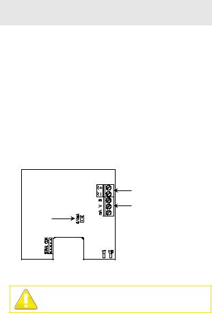
1.Connect the nominal 24 V supply on the PCB between the terminals + and -. Connect the common wire to terminal 0 and the other wire either to terminal V (voltage output) or to the terminal mA (current output).
2.Choose the current output with the jumper 0/4 mA
–4 ... 20mA: jumper shorts the pins (default)
–0 ... 20 mA: disconnect (do not discard) the jumper.
3.If the unit has an optional accessory (relay, display and relay, LonWorks interface, or temperature module), follow the procedure described in the applicable manuals before repositioning the cover.
4.Reposition the cover.
|
Power supply |
|
terminals |
Current |
Output signal |
terminals |
|
output |
|
jumper |
|
Figure 2 Jumper and Terminals
Connecting power wires to the output terminal can seriously damage the product.
4

User’s Guide_____________________________________________________ GMW20
Power Supply
Requirements
The GMW20 uses a nominal 24 VAC/VDC power supply maintaining a voltage of 18...30 VDC or 20...26 VAC for all load conditions and all mains voltages. Although the power input includes a halfwave rectifier, it is recommended to use a DC supply to avoid current peaks (Current consumption: peak 170 mA, average 85 mA).
Connections to a 24 VAC Power Supply
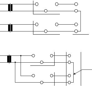
When more than one transmitter is connected to one 24 VAC transformer, a common loop is formed and the risk of a shortcircuit increases. To avoid this, separate floating supply for each transmitter is recommended (see Figure 3).
In case where several transmitters have to share one transformer, the phase ( ) must always be connected to 24V connector in each transmitter to maintain the "polarity" and to avoid short-circuit via shared common line at the controller as shown in Figure 4.
5
User’s Guide_____________________________________________________ GMW20
GMW20 CONTROLLER
24VAC |
Supply |
24V |
OUT |
Signal |
GND |
|
|||
voltage |
|
output |
GMW20
24VAC |
Supply |
24V |
OUT |
Signal |
GND |
|
|||
voltage |
|
output |
Figure 3 Connection of separate AC supplies (recommended)
|
GMW20 |
CONTROLLER |
||
|
24V |
OUT |
Signal |
|
24VAC |
|
GND |
|
|
|
output |
SHAR ED |
||
Supply |
|
|
|
|
|
|
|
COMMON |
|
voltage |
GMW20 |
|
LINE |
|
|
|
|
||
Supply |
24V |
OUT |
Signal |
|
|
GND |
|
||
voltage |
|
output |
|
|
Figure 4 Connection of one AC supply to several transmitters
6

User’s Guide_____________________________________________________ GMW20
Technical Data
Property
Measuring ranges
Accuracy at 25 °C against certified factory references (includes repeatability and calibration uncertainty)
Long-term stability
Response time (0 ... 63%)
Warm-up time
Operating temperature range
Storage temperature range
Humidity range
Output signal for CO2
Resolution of analog outputs
Optional outputs
Recommended external load current output
voltage output
Power supply
Power consumption
Housing material
Housing colour
Description / value
0 ... 2000 ppm CO2
0 ... 5000 ppm CO2
0 ... 10 000 ppm CO2
0 ... 20 000 ppm CO2
(2 % of range + 2 % of reading)
< 5 % of range / 5 years
1minute
1minute
15 minutes full specifications -5 … +45 °C (+23 … +113 °F) -20 ... +70 °C (-4 … +158 °F)
0 ... 85 % RH , non-condensing Selectable 0...20 mA or 4...20 mA and 0...10 V
8 bits
Relay output LonWorks® interfaces
max. 500 min. 1 k
nominal 24 VAC/VDC (18 ... 30 VDC)
< 2.5 W ABS plastic
NCS 0502-G50Y
7

User’s Guide_____________________________________________________ GMW20
Weight |
|
GMW21 |
100g |
GMW21 with display |
130g |
GMW22 |
90g |
GMW22 with display |
120g |
Relays and Other Accessories
Transmitters can be ordered with or without relays. The default relay trigger point has been set to 1000 ppm. This can be changed with the optional software kit 19222GM.
Description |
Order |
Display and relay output option |
GMI21 |
Relay output option |
GMR20 |
LonWorks module with CO2 signal |
GML20 |
(Not available when display option is added) |
|
LonWorks module with both CO2 signal and |
GML20T |
temperature signals (not available when display |
|
option is added) |
|
Analog temperature module for GMW21 |
GMA20T |
(not available when display option is added) |
|
Serial COM adapter |
19040GM |
Hand-held meter for field verification |
GM70 |
8

User’s Guide_____________________________________________________ GMW20
Dimensions (in Millimeters)
80
108.5
 60
60 

 83
83 
66.7
Figure 5 GMW21 and GMW21D
80
60
80
66.7
Figure 6 GMW22 and GMD22D
9

Legal notice
© Vaisala 2010
No part of this manual may be reproduced in any form or by any means, electronic or mechanical (including photocopying), nor may its contents be communicated to a third party without prior written permission of the copyright holder.
The contents are subject to change without prior notice.
Please observe that this manual does not create any legally binding obligations for Vaisala towards the customer or end user. All legally binding commitments and agreements are included exclusively in the applicable supply contract or Conditions of Sale.
Warranty
For warranty information, visit our Internet pages at www.vaisala.com/services/warranty.html
This product is covered by an extended 2 year warranty
Technical Support
For technical questions, contact the Vaisala technical support via email:
helpdesk@vaisala.com
For contact information of Vaisala Service Centers, see
www.vaisala.com/services/servicecenters.html
*M210196EN* |
|

Benutzerhandbuch
www.vaisala.com
CO2-Messwertgeber Vaisala CARBOCAP® der Serie GMW20
Benutzerhandbuch _______________________________________________ GMW20

Benutzerhandbuch _______________________________________________ GMW20
Inhalt |
|
Allgemeine Informationen zur Serie GMW20 .................... |
2 |
Montage ........................................................................................... |
2 |
Elektrische Anschlüsse ............................................................... |
4 |
Anforderungen der Stromversorgung.................................. |
5 |
Technische Daten ......................................................................... |
7 |
Relais und weiteres Zubehör.................................................... |
8 |
Abmessungen (in Millimeter) ................................................... |
9 |
1
Loading...