


USER'S GUIDE
Vaisala BAROCAP® Digital Barometer
PTB330
M210855EN-D
PUBLISHED BY |
|
|
|
Vaisala Oyj |
Phone (int.): |
+358 |
9 8949 1 |
P.O. Box 26 |
Fax: |
+358 |
9 8949 2227 |
FI-00421 Helsinki |
|
|
|
Finland |
|
|
|
Visit our Internet pages at http://www.vaisala.com/
© Vaisala 2012
No part of this manual may be reproduced, published or publicly displayed in any form or by any means, electronic or mechanical (including photocopying), nor may its contents be modified, translated, adapted, sold or disclosed to a third party without prior written permission of the copyright holder. Translated manuals and translated portions of multilingual documents are based on the original English versions. In ambiguous cases, the English versions are applicable, not the translations.
The contents of this manual are subject to change without prior notice.
This manual does not create any legally binding obligations for Vaisala towards customers or end users. All legally binding obligations and agreements are included exclusively in the applicable supply contract or the General Conditions of Sale and General Conditions of Service of Vaisala.
________________________________________________________________________________
Table of Contents |
|
CHAPTER 1 |
|
GENERAL INFORMATION............................................................................ |
9 |
About This Manual ................................................................... |
9 |
Contents of This Manual ....................................................... |
9 |
Version Information ............................................................. |
10 |
Documentation Conventions............................................... |
10 |
Safety....................................................................................... |
11 |
ESD Protection ....................................................................... |
11 |
Recycling ................................................................................ |
12 |
Trademarks ............................................................................. |
12 |
License Agreement ................................................................ |
12 |
Warranty.................................................................................. |
12 |
CHAPTER 2 |
|
PRODUCT OVERVIEW................................................................................ |
13 |
Introduction to PTB330.......................................................... |
13 |
Basic Features and Options................................................ |
14 |
Pressure Measurement....................................................... |
14 |
Outer Structure of the Barometer........................................ |
15 |
Inner Structure of the Barometer ........................................ |
16 |
CHAPTER 3 |
|
INSTALLATION............................................................................................ |
17 |
Mounting the Housing ........................................................... |
17 |
Standard Mounting without Mounting Plate ........................ |
17 |
Wall Mounting with Wall Mounting Kit................................. |
18 |
Mounting with DIN Rail Installation Kit ................................ |
19 |
Pole Installation with Installation Kit for Pole or Pipeline .... |
19 |
Mounting Rain Shield with Installation Kit ........................... |
22 |
Panel Mounting Frame........................................................ |
22 |
Pressure connections............................................................ |
24 |
General about Wiring and Grounding.................................. |
25 |
Cable Bushings ................................................................... |
25 |
Grounding the Cables ......................................................... |
26 |
Grounding the Barometer Housing ..................................... |
27 |
Alternate Wiring Systems...................................................... |
27 |
Signal and Power Supply Wiring......................................... |
28 |
M-12 (8-Pin) Connector....................................................... |
30 |
D-9 Connector..................................................................... |
31 |
Optional Modules ................................................................... |
32 |
AC Power Supply Module ................................................... |
32 |
Installation ...................................................................... |
33 |
Warnings ............................................................................. |
34 |
VAISALA ________________________________________________________________________ 1
USER'S GUIDE____________________________________________________________________
Galvanic Isolation for Output ............................................... |
37 |
Analog Output Module AOUT-1T ........................................ |
38 |
Installation and Wiring.................................................... |
38 |
Relay Module RELAY-1L .................................................... |
40 |
Installation and Wiring.................................................... |
40 |
Selecting the Activation State of the Relay ......................... |
41 |
RS-422/RS-485 Interface Module (RS485-1) ..................... |
42 |
Installation and Wiring.................................................... |
43 |
CHAPTER 4 |
|
OPERATION................................................................................................. |
47 |
Getting Started........................................................................ |
47 |
Display/Keypad (Optional)..................................................... |
47 |
Basic Display ....................................................................... |
47 |
Menus and Navigation.................................................... |
48 |
Pressure 3h Trend and Tendency Reading ........................ |
49 |
Using Basic Display........................................................ |
49 |
Pressure Tendency Graphics and Codes ...................... |
49 |
Using Serial Line ............................................................ |
51 |
Missing Trend................................................................. |
51 |
Graphic History.................................................................... |
51 |
Information Display.............................................................. |
53 |
Display Settings................................................................... |
54 |
Changing Quantities....................................................... |
54 |
Changing Units............................................................... |
54 |
Rounding ........................................................................ |
55 |
Backlight......................................................................... |
55 |
Contrast.......................................................................... |
55 |
Keypad Lock................................................................... |
55 |
Measuring Settings.............................................................. |
56 |
Diagnostic Settings.............................................................. |
56 |
Serial Interface Settings ...................................................... |
57 |
System Settings................................................................... |
58 |
Language ....................................................................... |
58 |
Menu PIN Lock............................................................... |
58 |
Factory Settings ............................................................. |
59 |
Clearing Graph Displays ................................................ |
59 |
Relay Settings ..................................................................... |
60 |
Relay Outputs................................................................. |
60 |
Testing the Operation of Relays..................................... |
61 |
Analog Output Settings ....................................................... |
62 |
Analog Output Quantities ............................................... |
62 |
Testing the Operation of Analog Outputs....................... |
62 |
Analog Output Fault Indication....................................... |
63 |
MI70 Link Interface Software for Data Handling.................. |
63 |
Serial Line Communication ................................................... |
64 |
User Port Connection .......................................................... |
65 |
Service Port Connection...................................................... |
66 |
Terminal Program Settings.................................................. |
66 |
Opening a Serial/USB connection.................................. |
67 |
List of Serial Commands ....................................................... |
68 |
General Settings ..................................................................... |
70 |
Changing Quantities and Units............................................ |
70 |
FORM............................................................................. |
70 |
2 ___________________________________________________________________ M210855EN-D
________________________________________________________________________________
UNIT............................................................................... |
73 |
DATE and TIME............................................................. |
75 |
Measurement Related Commands ..................................... |
77 |
TQFE.............................................................................. |
77 |
DPMAX .......................................................................... |
78 |
AVRG ............................................................................. |
79 |
HHCP ............................................................................. |
79 |
HQFE ............................................................................. |
80 |
HQNH............................................................................. |
80 |
ICAOQNH ...................................................................... |
81 |
PSTAB ........................................................................... |
82 |
User Port Serial Settings..................................................... |
84 |
SDELAY ......................................................................... |
84 |
SERI............................................................................... |
84 |
SMODE .......................................................................... |
85 |
INTV ............................................................................... |
86 |
ECHO............................................................................. |
86 |
System Information Commands.......................................... |
87 |
? ..................................................................................... |
87 |
ERRS ............................................................................. |
87 |
VERS ............................................................................. |
88 |
Resetting Barometer by Using Serial Line .......................... |
88 |
RESET ........................................................................... |
88 |
Locking Menu/Keypad by Using Serial Line ....................... |
89 |
LOCK ............................................................................. |
89 |
Data Recording....................................................................... |
90 |
Selecting Data Recording Quantities .................................. |
90 |
DSEL.............................................................................. |
90 |
View Recorded Data ........................................................... |
91 |
DIR ................................................................................. |
91 |
PLAY .............................................................................. |
92 |
DELETE/UNDELETE..................................................... |
93 |
Operating Relays.................................................................... |
93 |
Quantity for Relay Output.................................................... |
93 |
Measurement-Based Relay Output Modes......................... |
93 |
Relay Setpoints.............................................................. |
93 |
Hysteresis ...................................................................... |
95 |
Relay Indicating Barometer Error Status ............................ |
95 |
Enabling/Disabling Relays .................................................. |
96 |
Setting Relay Outputs ......................................................... |
96 |
RSEL.............................................................................. |
96 |
Testing the Operation of Relays.......................................... |
98 |
RTEST ........................................................................... |
98 |
Operating RS-485 Module ..................................................... |
99 |
Networking Commands....................................................... |
99 |
ADDR ........................................................................... |
100 |
SDELAY ....................................................................... |
100 |
SMODE POLL.............................................................. |
100 |
SCOM .......................................................................... |
100 |
OPEN ........................................................................... |
101 |
CLOSE ......................................................................... |
101 |
SEND ........................................................................... |
101 |
Operating Analog Output .................................................... |
102 |
Changing Output Mode and Range .................................. |
102 |
Analog Output Quantities .................................................. |
104 |
VAISALA ________________________________________________________________________ 3
USER'S GUIDE____________________________________________________________________
AMODE/ASEL .............................................................. |
|
104 |
Analog Output Tests.......................................................... |
|
105 |
ATEST.......................................................................... |
|
105 |
Analog Output Fault Indication Setting.............................. |
105 |
|
AERR............................................................................ |
|
105 |
CHAPTER 5 |
|
|
MAINTENANCE.......................................................................................... |
|
107 |
Periodic Maintenance........................................................... |
|
107 |
Cleaning ............................................................................ |
|
107 |
Error States ........................................................................... |
|
107 |
Technical Support ................................................................ |
|
110 |
Product Returns.................................................................... |
|
110 |
CHAPTER 6 |
|
|
CALIBRATION AND ADJUSTMENT......................................................... |
|
111 |
Pressure ................................................................................ |
|
111 |
Opening and Closing the Adjustment Mode...................... |
112 |
|
Pressure Adjustment ........................................................... |
|
113 |
Adjustments Using Display/Keypad .................................. |
|
114 |
Linear/Offset Adjustment Using Serial Line ...................... |
116 |
|
LCP1, LCP2, LCP3 ...................................................... |
|
116 |
Multipoint Adjustment Using Serial Line............................ |
118 |
|
MPCP1, MPCP2, MPCP3 ............................................ |
|
118 |
Analog Output Adjustment (Ch1)........................................ |
|
121 |
Using Display/Keypad ....................................................... |
|
121 |
Using Serial Line ............................................................... |
|
122 |
ACAL ............................................................................ |
|
122 |
Feeding Adjustment Information ........................................ |
|
123 |
Using Display/Keypad ....................................................... |
|
123 |
Using Serial Line ............................................................... |
|
123 |
CTEXT.......................................................................... |
|
123 |
CDATE ......................................................................... |
|
123 |
CHAPTER 7 |
|
|
TECHNICAL DATA .................................................................................... |
|
125 |
Specifications ....................................................................... |
|
125 |
Performance ...................................................................... |
|
125 |
Barometric pressure range 500 ... |
1100 hPa ............... |
125 |
Barometric pressure range 50 ... |
1100 hPa ................. |
125 |
Operating Environment ..................................................... |
|
126 |
Inputs and outputs............................................................. |
|
127 |
Mechanics ......................................................................... |
|
128 |
Technical Specifications of Optional Modules................... |
128 |
|
Options and Accessories .................................................... |
|
130 |
Dimensions (in mm) ............................................................. |
|
131 |
4 ___________________________________________________________________ M210855EN-D
________________________________________________________________________________
APPENDIX A |
|
CALCULATION FORMULAS .................................................................... |
133 |
ICAOQNH Mode for QNH and QFE............................. |
134 |
APPENDIX B |
|
UNIT CONVERSION TABLES................................................................... |
135 |
APPENDIX C |
|
PA11A EMULATION MODE ...................................................................... |
139 |
Activating the PA11A Emulation Mode.............................. |
139 |
PA11A Message Format ...................................................... |
140 |
VAISALA ________________________________________________________________________ 5
USER'S GUIDE____________________________________________________________________
List of Figures |
|
|
Figure 1 |
Barometer Body........................................................................ |
15 |
Figure 2 |
Open Barometer Interior........................................................... |
16 |
Figure 3 |
Standard Mounting ................................................................... |
17 |
Figure 4 |
Mounting with Wall Mounting Kit .............................................. |
18 |
Figure 5 |
Dimensions of Plastic Mounting Plate ...................................... |
18 |
Figure 6 |
Mounting with DIN Rail Installation Kit ..................................... |
19 |
Figure 7 |
Vertical Pole (Side)................................................................... |
20 |
Figure 8 |
Vertical Pole (Front).................................................................. |
20 |
Figure 9 |
Horizontal Pole ......................................................................... |
20 |
Figure 10 |
Mounting with Metal Wall Mounting Plate ................................ |
21 |
Figure 11 |
Dimensions of Metal Mounting Plate (mm) .............................. |
21 |
Figure 12 |
Mounting Rain Shield with Installation Kit ................................ |
22 |
Figure 13 |
Panel Mounting Frame ............................................................. |
23 |
Figure 14 |
Panel Mounting Dimensions..................................................... |
23 |
Figure 15 |
Cable Bushings......................................................................... |
25 |
Figure 16 |
Grounding the Screen of Electrical Cable ................................ |
26 |
Figure 17 |
Screw Terminal Block on Motherboard .................................... |
28 |
Figure 18 |
Wiring of Optional M-12 (8-Pin) Connector .............................. |
30 |
Figure 19 |
Wiring of Optional D-9 Connector............................................. |
31 |
Figure 20 |
AC Power Supply Module......................................................... |
32 |
Figure 21 |
Galvanic Power Isolation .......................................................... |
37 |
Figure 22 |
Analog Output 1 Module AOUT-1T .......................................... |
38 |
Figure 23 |
Analog Output Dip Switch Positions......................................... |
39 |
Figure 24 |
Relay Module............................................................................ |
41 |
Figure 25 |
RS485-1 Module....................................................................... |
42 |
Figure 26 |
4-Wire RS-485 Bus................................................................... |
44 |
Figure 27 |
2-Wire RS-485 Bus................................................................... |
45 |
Figure 28 |
Basic Display ............................................................................ |
47 |
Figure 29 |
Main Menu (Main Level) ........................................................... |
48 |
Figure 30 |
P3H Tendency............................................................................ |
49 |
Figure 31 |
Pressure Tendency Description ............................................... |
50 |
Figure 32 |
Graphical Display ..................................................................... |
51 |
Figure 33 |
Device Information on Display.................................................. |
53 |
Figure 34 |
Checking Stability of the Measurement.................................... |
57 |
Figure 35 |
Relay Indicators on Display ...................................................... |
60 |
Figure 36 |
Service Port Connector and User Port Terminal |
|
|
on Motherboard ........................................................................ |
64 |
Figure 37 |
Connection Example Between PC Serial Port and User Port .. |
65 |
Figure 38 |
Opening a Serial Connection.................................................... |
67 |
Figure 39 |
Relay Output Modes................................................................. |
94 |
Figure 40 |
FAULT STATUS Relay Output Mode....................................... |
95 |
Figure 41 |
Current/Voltage Switches of Output Module .......................... |
102 |
Figure 42 |
Dip Switch Selection Example................................................ |
103 |
Figure 43 |
Error Indicator and Error Message ......................................... |
108 |
Figure 44 |
Adjustment Menu.................................................................... |
112 |
Figure 45 |
PTB330 Adjustments.............................................................. |
113 |
Figure 46 |
Barometer Body Dimensions.................................................. |
131 |
Figure 47 |
Pressure Conversion Chart .................................................... |
135 |
6 ___________________________________________________________________ M210855EN-D
________________________________________________________________________________
List of Tables
Table 1 |
Manual Revisions ..................................................................... |
|
10 |
Table 2 |
Quantities Measured by PTB330 |
............................................. |
15 |
Table 3 |
Pin Assignments to RS-232-/485 Serial Output....................... |
30 |
|
Table 4 |
Pin Assignments to RS-232/485 Serial Output ........................ |
31 |
|
Table 5 |
Connecting the Twisted Pair Wires to the Screw Terminals .... |
44 |
|
Table 6 |
4-Wire (Switch 3: On)............................................................... |
|
45 |
Table 7 |
2-Wire (Switch 3: Off) ............................................................... |
|
45 |
Table 8 |
Periods for Trend and Max/Min Calculations ........................... |
52 |
|
Table 9 |
Graph Information Messages in Cursor Mode ......................... |
52 |
|
Table 10 |
Default Serial Communication Settings for the User Port ........ |
65 |
|
Table 11 |
Fixed Communication Settings for Service Port ...................... |
66 |
|
Table 12 |
FORM Modifiers ....................................................................... |
|
71 |
Table 13 |
Symbols Used in FORM Checksum Equations ....................... |
72 |
|
Table 14 |
Quantity Symbols ..................................................................... |
|
72 |
Table 15 |
Output Quantities and Units ..................................................... |
|
73 |
Table 16 |
Selection of Output Modes....................................................... |
|
85 |
Table 17 |
ERRS command line parameters |
............................................. |
88 |
Table 18 |
Error Messages ...................................................................... |
|
109 |
Table 19 |
Adjustment and Calibration Commands for Barometer |
|
|
|
Module P1 .............................................................................. |
|
112 |
Table 20 |
Barometric Pressure range 500 ... |
1100 hPa at 20°C............ |
125 |
Table 21 |
Barometric pressure range 50 ... |
1100 hPa at 20°C .............. |
125 |
Table 22 |
Temperature Dependence****................................................ |
|
126 |
Table 23 |
Total Accuracy at -40 ... +60°C (-40 ... +140 °F).................... |
126 |
|
Table 24 |
Long Term Stability ................................................................ |
|
126 |
Table 25 |
Operating Environment .......................................................... |
|
126 |
Table 26 |
Inputs and outputs.................................................................. |
|
127 |
Table 27 |
Mechanics .............................................................................. |
|
128 |
Table 28 |
AC Power Supply Module ...................................................... |
|
128 |
Table 29 |
Analog Output Module AOUT-1 ............................................. |
|
128 |
Table 30 |
Relay Module ......................................................................... |
|
129 |
Table 31 |
RS-422/RS-485 Module RS485-1.......................................... |
129 |
|
Table 32 |
Options and Accessories........................................................ |
|
130 |
Table 33 |
Symbols used in QNH calculation formulas........................... |
134 |
|
Table 34 |
Unit Conversion Table for all Pressure Quantities |
|
|
|
(Excluding Pxx and P3h) ........................................................ |
|
136 |
Table 35 |
Unit Conversion Table for Difference Pressure Pxx and |
|
|
|
Pressure Trend P3h Quantities ............................................... |
|
136 |
Table 36 |
Unit Conversion Table for Settings Pressure Stability |
|
|
|
PSTAB and Maximum Pressure Difference PMAX ............. |
136 |
|
Table 37 |
Unit Conversion Table for Settings HHCP and HQFE ........... |
137 |
|
Table 38 |
Unit Conversion Table for Settings HQNH............................. |
137 |
|
Table 39 |
Unit Conversion Table for Setting TQFE................................ |
137 |
|
VAISALA ________________________________________________________________________ 7
USER'S GUIDE____________________________________________________________________
This page intentionally left blank.
8 ___________________________________________________________________ M210855EN-D
Chapter 1 ________________________________________________________ General Information
CHAPTER 1
GENERAL INFORMATION
This chapter provides general notes for the manual and the product.
About This Manual
This manual provides information for installing, operating, and maintaining Vaisala BAROCAP® Digital Barometer PTB330.
Contents of This Manual
This manual consists of the following chapters:
-Chapter 1, General Information, provides general notes for the manual and the product.
-Chapter 2, Product Overview, introduces the features, advantages, and the product nomenclature of PTB330.
-Chapter 3, Installation, provides you with information about how to install the product.
-Chapter 4, Operation, contains information that is needed to operate the product.
-Chapter 5, Maintenance, contains information that is needed in the basic maintenance of the product.
-Chapter 6, Calibration and Adjustment, contains instructions for performing the calibration and adjustment of the product.
-Chapter 7, Technical Data, provides the technical data of the product.
-Appendix A, Calculation Formulas, contains the calculation formulas used by the product.
VAISALA ________________________________________________________________________ 9
USER'S GUIDE____________________________________________________________________
-Appendix B, Unit conversion tables, contains the unit conversion tables.
-Appendix C, PA11A Emulation Mode, describes the PA11A emulation mode of the PTB330 series.
Version Information
Table 1 |
Manual Revisions |
|
|
|
|
Manual Code |
|
Description |
M210855EN-D |
|
December 2012. This version. Command |
|
|
descriptions rewritten. Other, more minor |
|
|
changes throughout. |
M210855EN -C |
January 2008. Previous version. |
|
|
|
Documentation Conventions |
|
|
|
Throughout the manual, important safety considerations are |
|
|
|
highlighted as follows: |
|
|
|
|
|
|
WARNING |
Warning alerts you to a serious hazard. If you do not read and follow |
|
|
|
instructions very carefully at this point, there is a risk of injury or |
|
|
|
even death. |
|
|
|
|
|
|
|
|
|
CAUTION |
Caution warns you of a potential hazard. If you do not read and |
|
follow instructions carefully at this point, the product could be |
|
damaged or important data could be lost. |
|
|
NOTE |
Note highlights important information on using the product. |
|
|
10 __________________________________________________________________ M210855EN-D
Chapter 1 ________________________________________________________ General Information
Safety
|
|
The product delivered to you has been tested for safety and approved |
|
|
|
as shipped from the factory. Note the following precautions: |
|
|
|
|
|
|
WARNING |
Ground the product, and verify outdoor installation grounding |
|
|
|
periodically to minimize shock hazard. |
|
|
|
|
|
|
|
|
|
|
|
|
|
|
WARNING |
To avoid electric shock, never open the PTB330 enclosure while the |
|
|
|
transmitter is connected to mains power. |
|
|
|
|
|
|
|
|
|
CAUTION |
Do not modify the unit. Improper modification can damage the |
|
product or lead to malfunction. |
|
|
ESD Protection
Electrostatic Discharge (ESD) can cause immediate or latent damage to electronic circuits. Vaisala products are adequately protected against ESD for their intended use. However, it is possible to damage the product by delivering electrostatic discharges when touching, removing, or inserting any objects inside the equipment housing.
To make sure you are not delivering high static voltages yourself:
-Handle ESD sensitive components on a properly grounded and protected ESD workbench. When this is not possible, ground yourself to the equipment chassis before touching the boards.
-Ground yourself with a wrist strap and a resistive connection cord.
-When neither of the above is possible, touch a conductive part of the equipment chassis with your other hand before touching the boards.
-Always hold the boards by the edges and avoid touching the component contacts.
VAISALA _______________________________________________________________________ 11
USER'S GUIDE____________________________________________________________________
Recycling
Trademarks
BAROCAP® is a registered trademark of Vaisala. Windows is a registered trademark of Microsoft Corporation.
License Agreement
All rights to any software are held by Vaisala or third parties. The customer is allowed to use the software only to the extent that is provided by the applicable supply contract or Software License Agreement.
Warranty
Visit our Internet pages for standard warranty terms and conditions: www.vaisala.com/warranty.
Please observe that any such warranty may not be valid in case of damage due to normal wear and tear, exceptional operating conditions, negligent handling or installation, or unauthorized modifications. Please see the applicable supply contract or Conditions of Sale for details of the warranty for each product.
12 __________________________________________________________________ M210855EN-D
Chapter 2 __________________________________________________________ Product Overview
CHAPTER 2
PRODUCT OVERVIEW
This chapter introduces the features, advantages, and the product nomenclature of PTB330.
Introduction to PTB330
Vaisala BAROCAP® Digital Barometer PTB330 provides reliable pressure measurement in a wide range of applications. Digital outputs RS-232 (standard) or RS-422/485 (optional) can be selected. Alternatively, analog outputs can be chosen between current and optional voltage signals. A local graphical display is available as well. The quantities measured and calculated by PTB330 are presented in Table 2 on page 15.
The PTB330 barometer is available with one, two, or three barometer modules. The barometer can be used successfully both in accurate pressure measurement applications at room temperature and in demanding automatic weather station applications.
VAISALA _______________________________________________________________________ 13
USER'S GUIDE____________________________________________________________________
Basic Features and Options
-Applicable in industrial and meteorological areas
-Calculated aviation related output quantities: QFE and QNH
-1 ... 3 BARO-1 barometer modules (sensors)
-Barometer mounting accessories for multiple installation purposes
-Service port for MI70 Link Interface Software or PC
-Four module slots
-IP 65 housing
-Screw terminal, optional M12 connector or D-9 connector
-Optional graphical display showing the measurement trends of the quantities chosen by the user
-Optional modules: power supply module, RS-485 module, analog output module, and relay module
-Optional USB cable for service use or data transfer
Pressure Measurement
The PTB330 series barometers use a BAROCAP® silicon capacitive absolute pressure sensor developed by Vaisala for barometric pressure measurement applications. The BAROCAP® sensor has excellent hysteresis and repeatability characteristics, low temperature dependence, and a very good long-term stability. The BAROCAP® sensor is very robust and resistant to mechanical and thermal shocks.
The measurement principle of the PTB330 series digital barometers is based on an advanced RC oscillator and reference capacitors against which the capacitive pressure sensor is continuously measured. The microprocessor of the barometer performs compensation for pressure linearity and temperature dependence.
Each barometer module in PTB330 has its own adjustment coefficients for different reference pressures across the entire temperature range. This achieves the best possible accuracy needed in barometric pressure measurements.
14 __________________________________________________________________ M210855EN-D

Chapter 2 __________________________________________________________ Product Overview
Table 2 |
Quantities Measured by PTB330 |
|
|
|
|
Quantity |
|
Abbreviation |
Pressure (measures average |
P |
|
pressure from P1, P2, and P3) |
|
|
Pressure from barometer |
P1, P2, and P3 |
|
module 1 or 2 or 3 |
|
|
Temperature of barometer |
TP1, TP2, and TP3 |
|
module 1 or 2 or 3 |
|
|
Pressure trend (includes |
P3h |
|
pressure tendency on display) |
|
|
Pressure difference (P1 -P2) |
P12 |
|
Pressure difference (P1 -P3) |
P13 |
|
Pressure difference (P2-P3) |
P23 (available on serial port |
|
|
|
only) |
QNH pressure |
|
QNH |
QFE pressure |
|
QFE |
Height Corrected Pressure |
HCP |
|
Pressure tendency (available on |
A3h |
|
serial port only) |
|
|
Outer Structure of the Barometer
Figure 1 Barometer Body
Numbers refer to Figure 1 above:
1= Cable for signal/powering Ø 8 ... 11 mm
2= Pressure port
3= Cable for optional power supply/relay module Ø 8 ... 11 mm
4= Cover LED
5= Display with keypad (optional)
6= Cover screw (4 pcs)
VAISALA _______________________________________________________________________ 15
USER'S GUIDE____________________________________________________________________
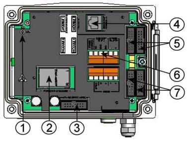
Inner Structure of the Barometer
Figure 2 Open Barometer Interior
Numbers refer to Figure 2 above:
1= Adjustment button with indicator LED
2= Galvanic isolation module (optional)
3= Power supply mode selections
(Do not change the factory settings!)
4= Service port (RS-232)
5= Module 1/Module 3 connectors
6= User port
7= Module 2/Module 4 connectors
16 __________________________________________________________________ M210855EN-D
Chapter 3 _______________________________________________________________ Installation
CHAPTER 3
INSTALLATION
This chapter provides you with information about how to install the product.
Mounting the Housing
The housing can be mounted either without the mounting plate or with optional mounting plates.
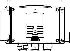
Standard Mounting without
Mounting Plate
Mount the housing by fastening the barometer to the wall with 4 screws, for example M6 (not provided).
|
169 |
96 |
|
|
7Ø |
Figure 3 |
Standard Mounting |
VAISALA _______________________________________________________________________ 17

USER'S GUIDE____________________________________________________________________
Wall Mounting with Wall Mounting
Kit
When mounting with wall mounting kit the mounting plate (Vaisala order code 214829) can be installed directly on wall or onto a standard wall box (also US junction box). When wiring through back wall, remove the plastic plug from the wiring hole in the barometer before mounting.
Figure 4 Mounting with Wall Mounting Kit
Numbers refer to Figure 4 above:
1= Plastic mounting plate
2= Mount the plate to wall with 4 screws M6 (not provided)
3= The arched side up
4= Fasten barometer to the mounting plate with 4 fixing screws M3 (provided)
5= Holes for wall/junction box mounting
Figure 5 Dimensions of Plastic Mounting Plate
18 __________________________________________________________________ M210855EN-D
Chapter 3 _______________________________________________________________ Installation
Mounting with DIN Rail Installation Kit
DIN rail installation kit includes a wall mounting kit, 2 clip-fasteners, and 2 screws M4 x 10 DIN 7985 (Vaisala order code 215094).
To mount PTB330 using the DIN rail installation kit:
1.Attach two spring holders to the plastic mounting plate by using the screws provided in the installation kit.
2.Fasten the barometer to the plastic mounting plate with 4 screws provided for that purpose.
3.Press the barometer onto the DIN rail so that the clip-fasteners snap into the rail.
Figure 6 Mounting with DIN Rail Installation Kit
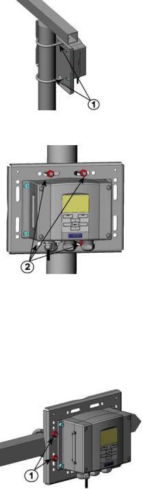
Pole Installation with Installation Kit for Pole or Pipeline
Installation kit for pole or pipeline (Vaisala order code: 215108) includes the metal mounting plate and 4 mounting nuts for pole mounting. When mounting, the arrow in the metal mounting plate must point upwards; see Figure 10 on page 21.
VAISALA _______________________________________________________________________ 19
USER'S GUIDE____________________________________________________________________
Figure 7 Vertical Pole (Side)
Figure 8 Vertical Pole (Front)
Numbers refer to Figure 8 above:
1= Fixing brackets (2 pcs) M8 (provided) for 30 ... 102 mm poles.
2= Mounting nuts M8 (4 pcs)
Figure 9 Horizontal Pole
Number refers to Figure 9 above: 1 = Mounting nuts M8 (4 pcs)
20 __________________________________________________________________ M210855EN-D

Chapter 3 _______________________________________________________________ Installation
Metal mounting plate is included in rain shield with installation kit and installation kit for pole or pipeline.
Figure 10 Mounting with Metal Wall Mounting Plate
Numbers refer to Figure 10 above:
1= Mount the plate to wall with 4 screws M8 (not provided)
2= Fasten the barometer to the mounting plate with 4 fixing screws M6 (provided)
3= Note the position of the arrow when mounting. This side must be up when mounting.
Figure 11 |
Dimensions of Metal Mounting Plate (mm) |
VAISALA _______________________________________________________________________ 21

USER'S GUIDE____________________________________________________________________
Mounting Rain Shield with
Installation Kit
Figure 12 Mounting Rain Shield with Installation Kit
Numbers refer to Figure 12 above:
1= Fasten the rain shield with installation kit (Vaisala order code: 215109) to the metal mounting plate with 2 (M6) mounting screws (provided).
2= Fasten the mounting plate with rain shield with installation kit to the wall or to the pole (see pole installation).
3= Fasten the barometer to the mounting plate with 4 fixing screws (provided).
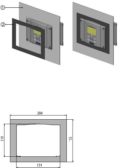
Panel Mounting Frame
To enable a neat and dirt-free embedded installation of the transmitter, a panel mounting frame is available as an option (Vaisala order code: 216038). The frame is a thin, flexible plastic frame for the transmitter, with adhesive tape on one side. The frame is used to hide any rough edges of the installation hole, and provide a more finished look. Note that the panel mounting frame is not intended to bear the weight of the transmitter, and does not include any mounting supports.
To use the panel mounting frame:
1.Use the frame as a template to mark the required size for the installation hole in the panel.
2.Cut the hole in the panel.
3.Mount the transmitter through the panel with suitable supports.
4.Remove the paper protecting the adhesive tape on the frame, and attach the frame around the transmitter. Refer to Figure 13 on page 23.
22 __________________________________________________________________ M210855EN-D
Chapter 3 _______________________________________________________________ Installation
Figure 13 Panel Mounting Frame
Numbers refer to Figure 13 above:
1= Panel (not included)
2= Panel mounting frame
Figure 14 Panel Mounting Dimensions
VAISALA _______________________________________________________________________ 23
USER'S GUIDE____________________________________________________________________
Pressure connections
The barometer is equipped with a barbed pressure fitting which is ideal for 3-4mm internal diameter tubing. If you require some other pressure fitting, you can replace the standard barbed fitting. The main pressure connector in the barometer housing has a metric M5 internal thread. It is, however, in practice possible to use pressure fittings with a non-metric 10-32 external thread together with this main pressure connector.
The barbed pressure fitting supplied with the barometer is not a static pressure head and cannot be used in turbulent or high-speed wind conditions. The barometric pressure measurement accuracy quoted for the PTB330 series digital barometers does not include any wind or air conditioning system induced measurement errors.
Protect the pressure fitting from the rain. If water gets into the pressure connector it may cause errors in the pressure measurement. The PTB330 barometers are designed to measure the pressure of clean, non-condensing, non-conducting, and non-corrosive gases only.
If you use Static Pressure Head SPH10/20 with PTB330, make sure the SPH10/20 tube is pointing downwards from PTB330. This way the condensed water does not accumulate inside the tube and cause measurement errors.
24 __________________________________________________________________ M210855EN-D
Chapter 3 _______________________________________________________________ Installation
General about Wiring and Grounding
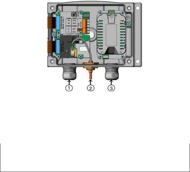
Cable Bushings
A single electrical cable with screen and three to ten wires is recommended for power and signal connections. The cable diameter should be 8...11 mm. The number of cable bushings depends on the barometer options. See the following recommendations for the cable bushings:
|
Figure 15 |
Cable Bushings |
|
|
Numbers refer to Figure 15 above: |
||
|
1 |
= Cable for signal/powering Ø 8 ... 11 mm |
|
|
2 |
= Pressure port |
|
|
3 |
= Cable for optional power supply/relay module Ø 8 ... 11 mm |
|
|
|
||
NOTE |
When there is high electric noise level (for example, near powerful |
||
electric motor) in the operating environment, Vaisala recommends using shielded cables or taking care that the signal cables are separated from other cables.
VAISALA _______________________________________________________________________ 25
USER'S GUIDE____________________________________________________________________
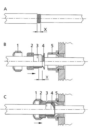
Grounding the Cables
To ensure the best possible EMC performance, you must ground the screen of the electrical cable as shown in 1212-005
Figure 16 below and in the instructions below that.
1212-005
Figure 16 Grounding the Screen of Electrical Cable
To ground the electrical cables:
1.Cut back outer sheath to desired length.
2.Cut back screen braiding or screen foil to dimension X (see
1212-005
Figure 16 |
above). |
3.Push the domed cap nut (item 1) and the seal insert with contact socket of the gland (item 2+3) onto the cable as shown in the diagram.
4.Bend over the screen braiding or screen foil by about 90° (item 4).
5.Push the seal insert with the contact socket of the gland (item 2+3) up to the screen braiding or screen foil.
26 __________________________________________________________________ M210855EN-D
Chapter 3 _______________________________________________________________ Installation
6.Mount lower part (item 5) on the housing.
7.Push the seal with the contact socket of the gland and (item 2+3) flush into the lower part (item 5).
8.Screw the domed cap nut (item 1) onto the lower part (item 5).
Grounding the Barometer Housing
If you need to ground the barometer housing, the grounding connector is found inside the housing. Make sure that different groundings are made to the same potential. Otherwise harmful ground currents may be generated.
If a galvanic isolation of the power supply line from the output signals is needed, the barometer can be ordered with an optional output isolation module. This module prevents harmful grounding loops.
Alternate Wiring Systems
There are four ways of powering the barometer: using basic wiring, the D-9 connector, the M-12 connector, or the optional external ACadapter.
The wiring system is selected when ordering the device. If a connector is needed for wiring, it is set at the factory.
-When using basic wiring, see section Signal and Power Supply Wiring on page 28.
-When using 8-pin connector, see section M-12 (8-Pin) Connector on page 30.
-When using D-9 connector, see section D-9 Connector on page 31.
-When using an optional external AC-adapter.
VAISALA _______________________________________________________________________ 27
USER'S GUIDE____________________________________________________________________
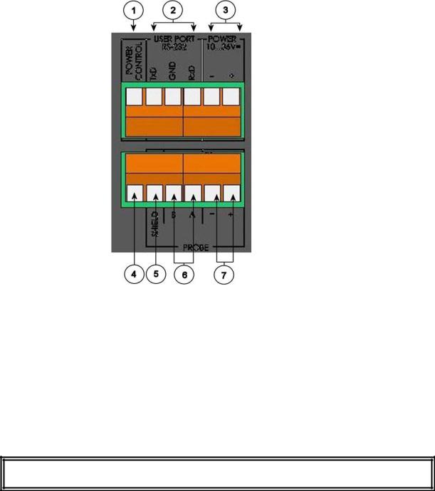
Signal and Power Supply Wiring
When wiring the power supply module, see section AC Power Supply
Module on page 32.
Figure 17 Screw Terminal Block on Motherboard
Numbers refer to Figure 17 above:
1= Power control (0VDC = OFF, 5VDC = ON, if feature enabled)
2= User port (RS-232 terminals)
3= Power supply terminals 10 ... 36 V DC
4= Test terminal (not connected, not used in PTB330)
5= Probe cable shield (not used in PTB330)
6= Probe bus (not used in PTB330)
7= Probe power (not used in PTB330)
WARNING Make sure that you connect only de-energized wires.
28 __________________________________________________________________ M210855EN-D
 Loading...