


HMT310
Table of contents
 Loading...
USER'S GUIDE
Vaisala HUMICAP® Humidity and
Temperature Transmitter
HMT310
M210619EN-E

PUBLISHED BY
Vaisala Oyj
Street address: Vanha Nurmijärventie 21, FI-01670 Vantaa, Finland
Mailing address: P.O. Box 26, FI-00421 Helsinki, Finland
Phone: +358 9 8949 1
Fax: +358 9 8949 2227
Visit our Internet pages at www.vaisala.com.
© Vaisala 2014
No part of this manual may be reproduced, published or publicly displayed in any form
or by any means, electronic or mechanical (including photocopying), nor may its
contents be modified, translated, adapted, sold or disclosed to a third party without prior
written permission of the copyright holder. Translated manuals and translated portions
of multilingual documents are based on the original English versions. In ambiguous
cases, the English versions are applicable, not the translations.
The contents of this manual are subject to change without prior notice.
This manual does not create any legally binding obligations for Vaisala towards
customers or end users. All legally binding obligations and agreements are included
exclusively in the applicable supply contract or the General Conditions of Sale and
General Conditions of Service of Vaisala.

_________________________________________________________________________________
Table of Contents
CHAPTER 1
GENERAL INFORMATION ............................................................................ 9
About This Manual ................................................................... 9
Version Information ............................................................. 10
Related Manuals ................................................................. 10
Documentation Conventions ............................................... 10
Safety ....................................................................................... 11
ESD Protection .................................................................... 11
Recycling ................................................................................ 12
Regulatory Compliances ....................................................... 12
Emissions ....................................................................... 12
Immunity ......................................................................... 12
Trademarks ............................................................................. 13
Software License .................................................................... 13
Warranty .................................................................................. 13
CHAPTER 2
PRODUCT OVERVIEW ................................................................................ 15
Introduction to HMT310 ......................................................... 15
Output Quantities ................................................................... 16
HMT310 Transmitter Parts ..................................................... 17
Probe Options ......................................................................... 18
Filter Options .......................................................................... 19
Sensor Options ....................................................................... 19
CHAPTER 3
INSTALLATION ............................................................................................ 21
Measuring at Overpressure ................................................... 21
Pressure Regulator Recommended .................................... 21
Selecting Location ................................................................. 21
Mounting the Transmitter /
Removing the Transmitter Unit ........................................... 22
Mounting the Transmitter with Optional Rain Shield ........... 24
Mounting the Rain Shield with Larger Mounting Plate ........ 24
Mounting the Probes ........................................................... 25
Beware of Temperature Differences .............................. 25
General Instructions for Probes with Cable ................... 26
HMT313 for General Use ............................................... 27
HMT314 for Pressurized Spaces ................................... 28
HMT315 for High Temperatures .................................... 29
HMT317 for Demanding Processes ............................... 30
HMT318 for Pressurized Pipelines ................................ 30
Tightening the Clasp Nut ............................................... 31
Connections ............................................................................ 33
Cable Wiring ........................................................................ 33
VAISALA _________________________________________________________________________ 3

User's Guide _______________________________________________________________________
Power Supply Requirements ................................................. 34
CHAPTER 4
OPERATION ................................................................................................. 35
Power Supply .......................................................................... 35
Transmitter Start-Up ............................................................... 35
Serial Line and Analog Communication Options ................ 36
RS-232 Serial Port Connection ........................................... 36
USB Connection .................................................................. 37
Installing the Driver for the USB Cable .......................... 37
Connection to an MI70 Hand-held Indicator ........................ 38
Terminal Program Settings .................................................... 39
Opening a Serial/USB Connection with PuTTY ............. 39
List of Serial Commands ....................................................... 40
Measurement Output .............................................................. 42
Start Continuous Outputting ................................................ 42
Stop Continuous Outputting ................................................ 42
Set Continuous Output Interval for RUN Mode ................... 42
Output Reading Once .......................................................... 43
Set Serial Interface Mode .................................................... 43
Serial Line Settings .............................................................. 43
Set Transmitter Address for Use in POLL Mode ................. 44
Temporarily Open Transmitter from POLL Mode
to Receive Serial Commands .............................................. 44
Set Transmitter in POLL Mode ............................................ 45
Output Formatting .................................................................. 45
Set Serial Output Format ..................................................... 45
Set Time and Date ............................................................... 47
Add Time and Date to SEND and R Outputs ...................... 47
Select Metric or Nonmetric Output Units ............................. 48
Output State of Chemical Purge or Sensor Heating
(with SEND and R Commands) ........................................... 49
Other Commands.................................................................... 50
Check Transmitter Settings ................................................. 50
Serial Bus Echo ................................................................... 50
All Devices in POLL Mode Send Their Addresses .............. 51
List Commands .................................................................... 51
Set Ambient Pressure for Calculations ................................ 51
Set Result Filtering .............................................................. 52
Reset Transmitter ................................................................ 53
Display Error Messages ...................................................... 53
Setting, Scaling and Testing Analog Outputs ..................... 54
Set Analog Output Mode ..................................................... 54
Select Parameter for Analog Outputs .................................. 54
Scale Analog Outputs .......................................................... 55
Test Analog Outputs ............................................................ 56
Test Analog Outputs for Desired Readings ......................... 56
Set Error Outputs ................................................................. 57
Chemical Purge (Optional) .................................................... 57
General ................................................................................ 57
Automatic/Manual Chemical Purge ..................................... 58
Automatic Chemical Purge Settings..................................... 59
Turn ON/OFF Automatic Chemical Purge ........................... 59
Set Chemical Purge Interval ................................................ 59
4 ____________________________________________________________________ M210619EN-E

_________________________________________________________________________________
Chemical Purge in Powerup ................................................ 60
Chemical Purge Activated Manually .................................... 60
Starting Manual Chemical Purge ........................................ 60
Sensor Heating (Optional) ..................................................... 61
General ................................................................................ 61
HMT317 Fuel Cell Model Heating Settings .................... 61
Setting Humidity Sensor Heating ......................................... 62
Sensor Heating ON/OFF ..................................................... 62
Setting Heating Parameters ................................................ 62
CHAPTER 5
MAINTENANCE ........................................................................................... 65
Periodic Maintenance ............................................................ 65
Calibration Interval .............................................................. 65
Replacing Consumables........................................................ 65
Changing the Filter .............................................................. 65
Changing the Sensor .......................................................... 66
Technical Support .................................................................. 67
Product Returns ..................................................................... 67
CHAPTER 6
CALIBRATION AND ADJUSTMENT ........................................................... 69
Calibration and Adjustment Commands .............................. 70
Revert to Factory Calibration .............................................. 70
View Current Offset and Gain Adjustment .......................... 70
Relative Humidity Calibration after Sensor Change............ 71
Set Calibration Information Text.......................................... 71
Set Calibration Date ............................................................ 72
Analog Output Calibration ................................................... 72
Multipoint Relative Humidity Adjustment ............................. 73
Relative Humidity Calibration and Adjustment
(in Two Points) ........................................................................ 73
Low End Adjustment ........................................................... 74
High End Adjustment .......................................................... 75
Temperature Calibration and Adjustment
(in One Point) .......................................................................... 76
Humidity Calibration and Adjustment
(in One Point) .......................................................................... 77
Multipoint Adjustment Using Serial Line ............................. 78
MPC Command Syntax ................................................. 78
Example Multipoint Adjustment Procedure .................... 79
Adjustment Using an MI70 Indicator .................................... 81
Starting MI70 Adjustment .................................................... 81
Adjusting RH with MI70 ....................................................... 82
1-point RH Adjustment ................................................... 82
2-point RH Adjustment ................................................... 82
LiCl – NaCl automatic adjustment .................................. 83
Adjusting T with MI70 .......................................................... 83
1-point T adjustment ...................................................... 84
2-point T adjustment ...................................................... 84
Environment Settings .......................................................... 85
Last Adjustment Date .......................................................... 85
VAISALA _________________________________________________________________________ 5

User's Guide _______________________________________________________________________
CHAPTER 7
TECHNICAL DATA ...................................................................................... 87
Specifications ......................................................................... 87
Calculated Variables ............................................................ 90
Accuracies of Calculated Variables ..................................... 90
Accuracy of Dewpoint Temperature °C .......................... 90
Accuracy of Mixing Ratio g/kg
(Ambient Pressure 1013 mbar) ...................................... 90
Accuracy of Wet Bulb Temperature °C .......................... 91
Accuracy of Absolute Humidity g/m³ .............................. 91
Dewpoint Temperature ........................................................ 92
Spare Parts and Accessories ................................................ 93
Dimensions in mm (inches) ................................................... 94
Transmitter Enclosure and Mounting Plate Dimensions ..... 94
Rain Shield Dimensions ...................................................... 95
Probe Dimensions ............................................................... 96
HMT311 .......................................................................... 96
HMT313 .......................................................................... 96
HMT314 .......................................................................... 97
HMT315 .......................................................................... 97
HMT317 .......................................................................... 98
HMT318 .......................................................................... 98
APPENDIX A
PROBE INSTALLATION KITS AND INSTALLATION EXAMPLES ........... 99
Duct Installation Kits (for HMT313/317/315) ......................... 99
Pressure-Tight Swagelok Installation Kits
(for HMT317) .......................................................................... 100
RH Probe Installation ......................................................... 100
Examples of Vapor-Tight Installations
with Cable Gland................................................................... 101
RH Probe Installations (for HMT313/317) ......................... 101
Ball Valve Installation kit for HMT318 ................................. 102
6 ____________________________________________________________________ M210619EN-E

_________________________________________________________________________________
List of Figures
Figure 1 HMT310 Transmitter Parts ....................................................... 17
Figure 2 HMT310 Probes ....................................................................... 18
Figure 3 Mounting with Mounting Plates ................................................ 22
Figure 4 Mounting Plate Dimensions...................................................... 23
Figure 5 Rain Shield with Larger Mounting Plate ................................... 24
Figure 6 Measurement Error at 100 %RH when Difference Between
Ambient and Sensor Temperature is 1 °C ............................... 25
Figure 7 Horizontal Mounting of Probe ................................................... 26
Figure 8 Vertical Mounting of Probe ....................................................... 27
Figure 9 HMT314 Installation ................................................................. 28
Figure 10 Marking the Nut ........................................................................ 29
Figure 11 HMT318 Probe Dimensions (in mm) ........................................ 30
Figure 12 Sealing of Fitting Body into Process ........................................ 31
Figure 13 Tightening the Clasp Nut .......................................................... 32
Figure 14 8-Pin Connector (Left) and
Screw Terminal Connector (Right) ........................................... 33
Figure 15 PuTTY Serial Line Configuration .............................................. 39
Figure 16 Decrease of Sensor Gain Due to Interfering Chemical and
Effect of Chemical Purge Process ........................................... 58
Figure 17 Changing the Sensor ................................................................ 67
Figure 18 Location of Adjustment Button ................................................. 74
Figure 19 Accuracy over Temperature Range ......................................... 88
Figure 20 Accuracy in Dewpoint Measurement (°C) ................................ 92
Figure 21 Transmitter Enclosure and Mounting Plate Dimensions .......... 94
Figure 22 Rain Shield Dimensions (Back) ................................................ 95
Figure 23 Rain Shield Dimensions (Side and Outer) ............................... 95
Figure 24 Probe Dimensions .................................................................... 96
Figure 25 HMT313 Dimensions ................................................................ 96
Figure 26 HMT314 Dimensions ................................................................ 97
Figure 27 HMT315 Dimensions ................................................................ 97
Figure 28 HMT317 Dimensions ................................................................ 98
Figure 29 HMT318 Dimensions ................................................................ 98
Figure 30 Duct Installation Kit ................................................................... 99
Figure 31 Swagelok Installation Kit for RH Probe .................................. 100
Figure 32 Cable Installation with Cable Gland AGRO ............................ 101
Figure 33 Probe Installation with Cable Gland ....................................... 102
Figure 34 HMT318 Ball Valve Assembly Installation .............................. 103
VAISALA _________________________________________________________________________ 7

User's Guide _______________________________________________________________________
List of Tables
Table 1 Manual Revisions ..................................................................... 10
Table 2 Related Manuals ....................................................................... 10
Table 3 HMT310 Output Quantities ....................................................... 16
Table 4 HMT318 Probe Dimensions ..................................................... 31
Table 5 Current Consumption by Output Type/Function ....................... 34
Table 6 Measurement Output ................................................................ 40
Table 7 Output Formatting ..................................................................... 40
Table 8 Other Commands ..................................................................... 41
Table 9 Setting, Scaling and Testing Analog Outputs ........................... 41
Table 10 Calibration and Adjustment* ..................................................... 41
Table 11 Chemical Purge ........................................................................ 41
Table 12 Sensor Heating ......................................................................... 41
Table 13 Quantity Abbreviations for FORM Command ........................... 46
Table 14 Modifiers ................................................................................... 46
Table 15 Output Quantities and their Metric and Nonmetric Units .......... 48
Table 16 Pressure Conversion Chart ...................................................... 52
Table 17 Output Quantities and their Metric and Nonmetric Units .......... 55
Table 18 Example List for Multipoint Correction ...................................... 79
Table 19 Relative Humidity Specifications .............................................. 87
Table 20 Temperature Specifications and
Operating Pressure Ranges ..................................................... 88
Table 21 Electrical Connections .............................................................. 89
Table 22 General ..................................................................................... 89
Table 23 Calculated Variables (Typical Ranges) .................................... 90
Table 24 Spare Parts and Accessories ................................................... 93
8 ____________________________________________________________________ M210619EN-E

Chapter 1 _________________________________________________________ General Information
CHAPTER 1
GENERAL INFORMATION
This chapter provides general notes for the manual and the HMT310.
About This Manual
This manual provides information for installing, operating, and
maintaining Humidity and Temperature Transmitter HMT310.
This manual consists of the following chapters:
- Chapter 1, General Information, provides general notes for the manual
and the HMT310.
- Chapter 2, Product Overview, introduces the features, advantages, and
the product nomenclature.
Chapter 3, Installation, provides you with information that is intended
to help you install the HMT310.
Chapter 4, Operation, contains information that is needed to operate
the HMT310.
- Chapter 5, Maintenance, provides information that is needed in basic
maintenance of the HMT310.
- Chapter 6, Calibration and Adjustment, describes the relative humidity
and temperature adjustment procedures.
- Chapter 7, Technical Data, provides the technical data of the
HMT310.
- Appendix A describes the available probe installation kits and
provides some installation examples.
VAISALA _________________________________________________________________________ 9

User's Guide _______________________________________________________________________
Manual Code
Description
M210619EN-E
March 2014. This manual. New software
version updated, quality improvement updates.
M210619EN-D
November 2009 - Removed HUMICAP® 180,
sensor options. Updated Technical Data.
M210619EN-C
September 2007 - Added HUMICAP® 180R and
HUMICAP® 180RC as sensor options.
Manual Code
Manual Name
M210297EN
Vaisala HUMICAP® Hand-Held Humidity and
Temperature Meter HM70 User’s Guide
M210185EN
Vaisala Humidity calibrator HMK15 User’s Guide
Version Information
Table 1 Manual Revisions
functionality applicable from version 2.0.1 onward.
Voltage output added to analog output options, new
voltage parameters in the AMODE command.
Multipoint calibration instructions and MPC
command added. Added information on filter and
sensor options, rain shield, MI70 hand-held
indicator, and USB connection. Transmitter plastic
housing material changed to PPS. Updated serial
terminal instructions, list of optional accessories
and operating voltage and power consumption
specifications. Calculated variables and fuel cell
heating information added. Document template
HUMICAP® 180C and HUMICAP® 180L2 from
Related Manuals
Table 2 Related Manuals
Documentation Conventions
Throughout the manual, important safety considerations are highlighted
as follows:
WARNING
CAUTION
Warning alerts you to a serious hazard. If you do not read and follow
instructions very carefully at this point, there is a risk of injury or even
death.
Caution warns you of a potential hazard. If you do not read and follow
instructions carefully at this point, the product could be damaged or
important data could be lost.
NOTE
10 ___________________________________________________________________ M210619EN-E
Note highlights important information on using the product.

Chapter 1 _________________________________________________________ General Information
Ground the product and verify outdoor installation grounding
periodically to minimize shock hazard.
Do not modify the unit. Improper modification can damage the product
or lead
Do not touch the sensor plate.
In pressurized processes it is essential to tighten the supporting nuts and
screws very carefully to prevent loosening of the probe by the action of
pressure.
Take care not to da
probe less tight and may prevent it from going through the clasp nut.
Safety
The Humidity and Temperature Transmitter HMT310 delivered to you
has been tested for safety and approved as shipped from the factory. Note
the following precautions:
WARNING
CAUTION
to malfunction.
CAUTION
CAUTION
CAUTION
mage the probe body. A damaged body makes the
ESD Protection
Electrostatic Discharge (ESD) can cause immediate or latent damage to
electronic circuits. Vaisala products are adequately protected against
ESD for their intended use. It is possible to damage the product,
however, by delivering electrostatic discharges when touching,
removing, or inserting any objects inside the equipment housing.
To make sure you are not delivering high static voltages yourself:
- Handle ESD sensitive components on a properly grounded and
protected ESD workbench.
- When an ESD workbench is not available, ground yourself to the
equipment chassis with a wrist strap and a resistive connection cord.
- If you are unable to take either of the above precautions, touch a
conductive part of the equipment chassis with your other hand before
touching ESD sensitive components.
- Always hold component boards by the edges and avoid touching the
component contacts.
VAISALA ________________________________________________________________________ 11

User's Guide _______________________________________________________________________
Test
Complies with Standard
Radiated emissions
EN/IEC 55022 / CISPR16/22 Class B
Test
Complies with Standard
Electrostatic discharge
(ESD)
EN/IEC 61000-4-2
Radiated immunity
EN/IEC 61000-4-3
EFT burst (Electric fast
transients)
EN/IEC 61000-4-4
Surge
EN/IEC 61000-4-5
Conducted immunity
EN/IEC 61000-4-6
Recycling
Recycle all applicable material.
Dispose of the unit according to statutory regulations. Do not dispose of
with regular household refuse.
Regulatory Compliances
The Humidity and Temperature Transmitter HMT310 complies with the
following performance and environmental test standards:
- EMC standard EN61326-1, Industrial environment.
Emissions
Immunity
12 ___________________________________________________________________ M210619EN-E

Chapter 1 _________________________________________________________ General Information
Trademarks
HUMICAP® is a registered trademark of Vaisala.
Windows® is a registered trademark of Microsoft Corporation in the
United States and/or other countries.
Software License
This product contains software developed by Vaisala. Use of the software
is governed by license terms and conditions included in the applicable
supply contract or, in the absence of separate license terms and
conditions, by the General License Conditions of Vaisala Group.
Warranty
Visit our Internet pages for standard warranty terms and conditions:
www.vaisala.com/warranty.
Please observe that any such warranty may not be valid in case of
damage due to normal wear and tear, exceptional operating conditions,
negligent handling or installation, or unauthorized modifications. Please
see the applicable supply contract or Conditions of Sale for details of the
warranty for each product.
VAISALA ________________________________________________________________________ 13

User's Guide _______________________________________________________________________
This page intentionally left blank.
14 ___________________________________________________________________ M210619EN-E

Chapter 2 ___________________________________________________________ Product Overview
CHAPTER 2
PRODUCT OVERVIEW
This chapter introduces the features, advantages, and the product
nomenclature.
Introduction to HMT310
The Vaisala HUMICAP® Humidity and Temperature Transmitter
HMT310 is a small size humidity and temperature transmitter that
powers up with 10 ... 35 VDC (mode-dependent power supply
requirements). HMT310 uses Vaisala’s HUMICAP® capacitive thin-film
polymer sensor for humidity and temperature measurements: for more
information on HMT310 sensors, see section Sensor Options on page 19.
HMT310 supports the following output alternatives:
- Analog outputs 0/4 ... 20 mA and 0 … 5/10 V (1 … 5 V available as
scaled output: see section Setting, Scaling and Testing Analog Outputs
on page 54).
- RS-232 serial line
- USB cable (optional accessory, order code 238607)
- MI70 hand-held indicator connection (optional connection cable
DRW216050SP)
The following optional functions are available:
- Several probes for various applications
- Calculated humidity quantities
- Different mounting kits, rain shield, sensor protection options and
probe cable lengths
- Warmed probe and sensor heating for high humidity conditions
(HMT317)
- Chemical purge for applications where there is a risk of interfering
chemicals in the measuring environment
VAISALA ________________________________________________________________________ 15

User's Guide _______________________________________________________________________
Quantity
Abbreviation
Metric Unit
Nonmetric Unit
Relative humidity
RH
%RH
%RH
Temperature
T
°C
°F
Dewpoint/Frostpoint
TDF
°C
°F
Dewpoint
TD
°C
°F
Absolute humidity
A
g/m3
gr/ft3
Mixing ratio
X
g/kg
gr/lb
Wet bulb temperature
TW
°C
°F
Humid air volume/ dry air
volume
PPM (parts per
million)
ppm
ppm
Water vapor pressure
PW
hPa
psi
Saturation water vapor
pressure
PWS
hPa
psi
Enthalpy
H
kJ/kg
Btu/lb
Output Quantities
Table 3 HMT310 Output Quantities
NOTE
Only quantities selected when ordering the device can be selected for an
output quantity.
16 ___________________________________________________________________ M210619EN-E
Chapter 2 ___________________________________________________________ Product Overview
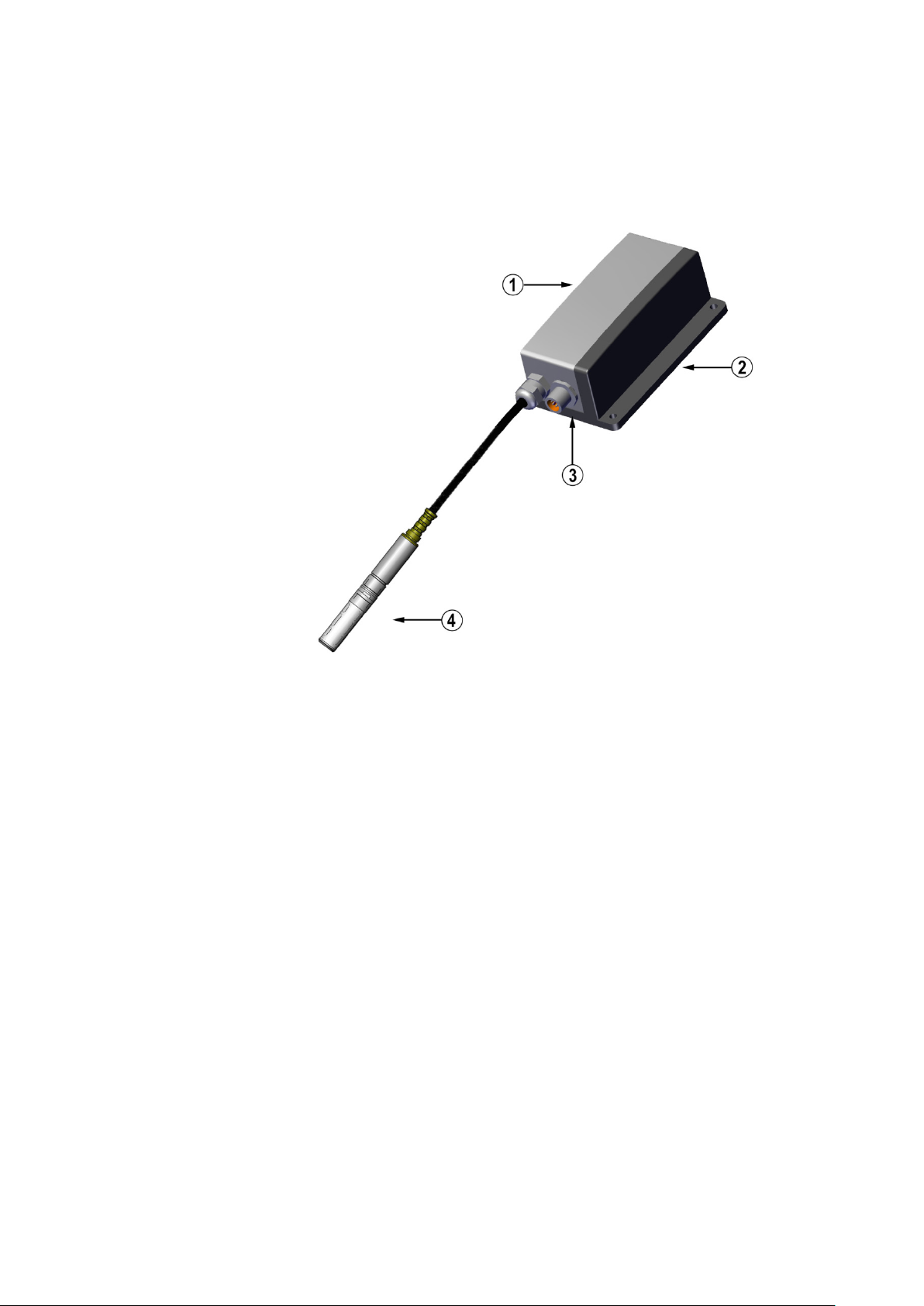
The following numbers refer to Figure 1 above:
1 = Transmitter unit
2 = Mounting plate (smaller mounting plate also available)
3 = Connector for signal output and power supply. Available with
female connector with 5 m cable or screw terminal connector.
4 = Probe
HMT310 Transmitter Parts
Figure 1 HMT310 Transmitter Parts
1403-180
VAISALA ________________________________________________________________________ 17

User's Guide _______________________________________________________________________
The following numbers refer to Figure 2 above:
1 = HMT311 for wall mounting
2 = HMT313 for general use
3 = HMT314 for pressurized spaces up to 100 bar
4 = HMT315 for high temperatures up to 180 °C (242 mm probe
length, vapor-tight)
5 = HMT317 for demanding processes (warmed and vapor-tight
probe)
6 = HMT318 for pressurized pipelines (40 bar, ball valve)
Probe Options
Figure 2 HMT310 Probes
*) Flange for HMT315 is available as an option
Probe cable lengths: 2, 5 and 10 m.
0507-033
18 ___________________________________________________________________ M210619EN-E

Chapter 2 ___________________________________________________________ Product Overview
Filter Options
There are several filter types for HMT310. All filters are 12 mm in
diameter with a female thread, and are compatible with all HMT310
probe models. The filters recommended for a probe type can be selected
on the corresponding HMT310 order form.
For a list of the available filters and ordering information, see section
Spare Parts and Accessories on page 93.
Sensor Options
HMT310 uses Vaisala’s HUMICAP® capacitive thin-film polymer sensor
for humidity and temperature measurements. The HUMICAP® sensor
options (selected when ordering according to transmitter type and
application, also available as accessories) include:
- HUMICAP®180R: general purpose humidity and temperature sensor
- HUMICAP® 180RC: composite sensor for chemical purge and probe
heating
- HUMICAP®180VHP: catalytic sensor designed for environments
with vaporized hydrogen peroxide (H2O2)
- HUMICAP®180VHPC: catalytic sensor with chemical purge for
H2O2 environments
HMT310 also uses the Pt 100 (Pt 100 RTD Class F0.1 IEC 60751)
temperature sensor.
The Vaisala HUMICAP® sensor is compatible with direct H2O2
exposure even at high concentrations and hundreds of H2O2 cycles up to
saturation. The long term performance is very good at concentrations
higher than typically used for sterilization. However, for applications
where full saturation is possible, Vaisala recommends using either the
HUMICAP®180VHP/180VHPC catalytic sensor, or the catalytic filter
(order code 231865) for HUMICAP®180R/180RC sensors to protect the
sensor and extend the calibration interval.
VAISALA ________________________________________________________________________ 19

User's Guide _______________________________________________________________________
This page intentionally left blank.
20 ___________________________________________________________________ M210619EN-E

Chapter 3 ________________________________________________________________ Installation
In pressurized processes it is essential to tighten the supporting nuts and
screws very carefully to
pressure.
CHAPTER 3
INSTALLATION
This chapter provides you with information that is intended to help you
install the HMT310.
Measuring at Overpressure
HMT314 and HMT318 are designed for humidity measurement at
overpressure. The maximum measurement pressures depend on the probe
as follows:
CAUTION
- HMT314: 0 ... 100 bar (10 MPa), for pressurized rooms and processes,
probe is provided with a nut, fitting screw and sealing washer
- HMT318: 0 ... 40 bar (4 MPa), for pressurized pipelines, ball valve set
available
The actual pressure in the process or sampling cell needs to be set to the
transmitter by using the serial line command PRES (Set Ambient
Pressure for Calculations).
prevent loosening of the probe by the action of
Pressure Regulator Recommended
When sampling pressurized processes exceeding the maximum
measurement pressure of the probe, the pressure in the measurement
chamber must be regulated to acceptable level or below. It is
recommended to use a pressure regulator before the measurement
chamber to prevent significant pressure variations.
Selecting Location
Finding a suitable site for the Humidity and Temperature Transmitter
HMT310 is important for getting representative ambient measurements.
The site should represent the general area of interest.
VAISALA ________________________________________________________________________ 21
User's Guide _______________________________________________________________________
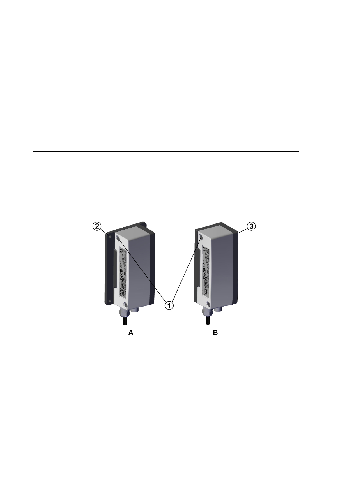
The following letters and numbers refer to Figure 3 above:
A = Mounting with larger mounting plate (mount from flanges)
B = Mounting with smaller mounting plate (remove the transmitter
and mount using the holes in mounting plate base)
1 = Two Allen screws for fastening or removing the transmitter
module (Allen key provided)
2 = Four screw holes (Ø 4.5 mm) for wall mounting (screws not
provided)
3 = Two screw holes (Ø 6.0 mm) on the base of the plate for wall
mounting (screws not provided)
Mounting the Transmitter/Removing the Transmitter Unit
Select a place with stable conditions for mounting the transmitter. Do not
expose the transmitter to direct sunlight or rain. Always mount the
transmitter housing with the cable bushings pointing downwards.
NOTE
If the transmitter is mounted outdoors cover it with a shelter (purchased
by customer). A rain shield designed for HMT310 is available as an
optional accessory. For information on ordering accessories, see section
Spare Parts and Accessories on page 93.
1. Mount the plate onto the wall with four/two screws
(Ø 4.5 mm/6.0 mm).
2. Place the transmitter onto the mounting plate and fasten it with two
Allen screws.
The transmitter module can be unfastened for calibration by releasing the
two Allen screws on the left side.
Figure 3 Mounting with Mounting Plates
22 ___________________________________________________________________ M210619EN-E
1403-181
Chapter 3 ________________________________________________________________ Installation
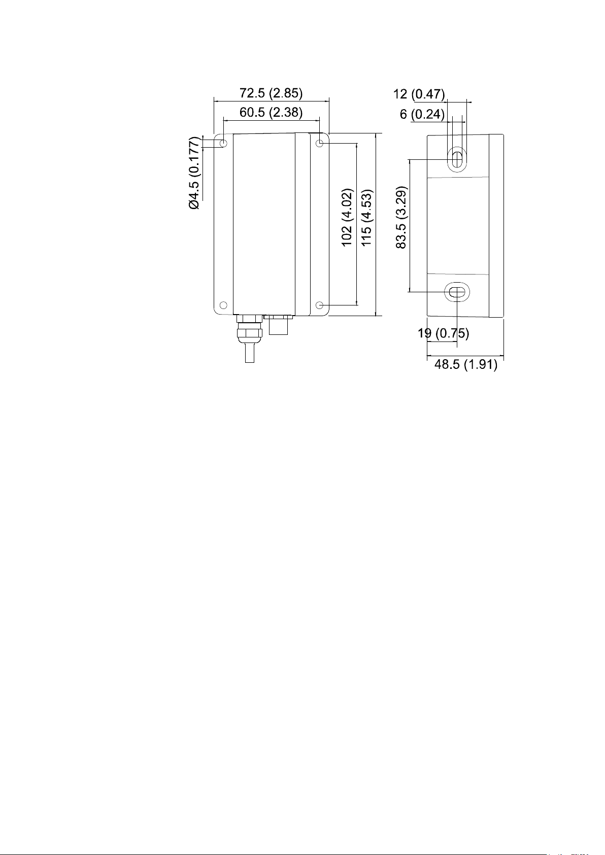
The following letters refer to Figure 4 above:
A = Larger mounting plate dimensions
B = Smaller mounting plate dimensions
A B
Figure 4 Mounting Plate Dimensions
0507-035
VAISALA ________________________________________________________________________ 23
User's Guide _______________________________________________________________________
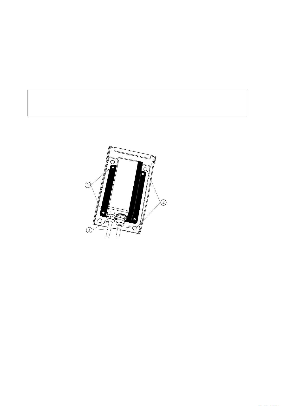
The following numbers refer to
1 = Transmitter’s larger mounting plate: attaches to rain shield from
flanges with four Ø 4.5 mm screws (not provided).
2 = Rain shield: Four Ø 8.5 mm holes for (U-bolt) mounting. The
maximum diameter of the pole in U-bolt mounting is 60 mm.
3 = Rain shield: Four Ø 4.5 mm screw holes for mounting.
Mounting the Transmitter with Optional Rain Shield
If you mount HMT310 outdoors, use a shelter to protect the transmitter.
An HMT310 rain shield is available from Vaisala as an optional
accessory (order code ASM211103).
NOTE
Vaisala does not recommend installing the transmitter outdoors with the
smaller mounting plate (without flanges). Use the larger mounting plate
with flanges for outdoor installations.
Mounting the Rain Shield with Larger Mounting Plate
1311-251
Figure 5 Rain Shield with Larger Mounting Plate
Figure 5 above:
The transmitter’s larger mounting plate (see Figure 3 on page 22) is
attached to the rain shield from the mounting plate’s flanges using four
Ø 4.5 mm screws. The rain shield has Ø 4.5 mm and Ø 8.5 mm holes for
mounting with screws or U-bolts.
For rain shield measurements, see section Rain Shield Dimensions on
page 95.
24 ___________________________________________________________________ M210619EN-E
Chapter 3 ________________________________________________________________ Installation
Mounting the Probes
Do not unsolder and then again resolder the probe cable from the mother
board during installation; this may alter the humidity calibration of the
transmitter.
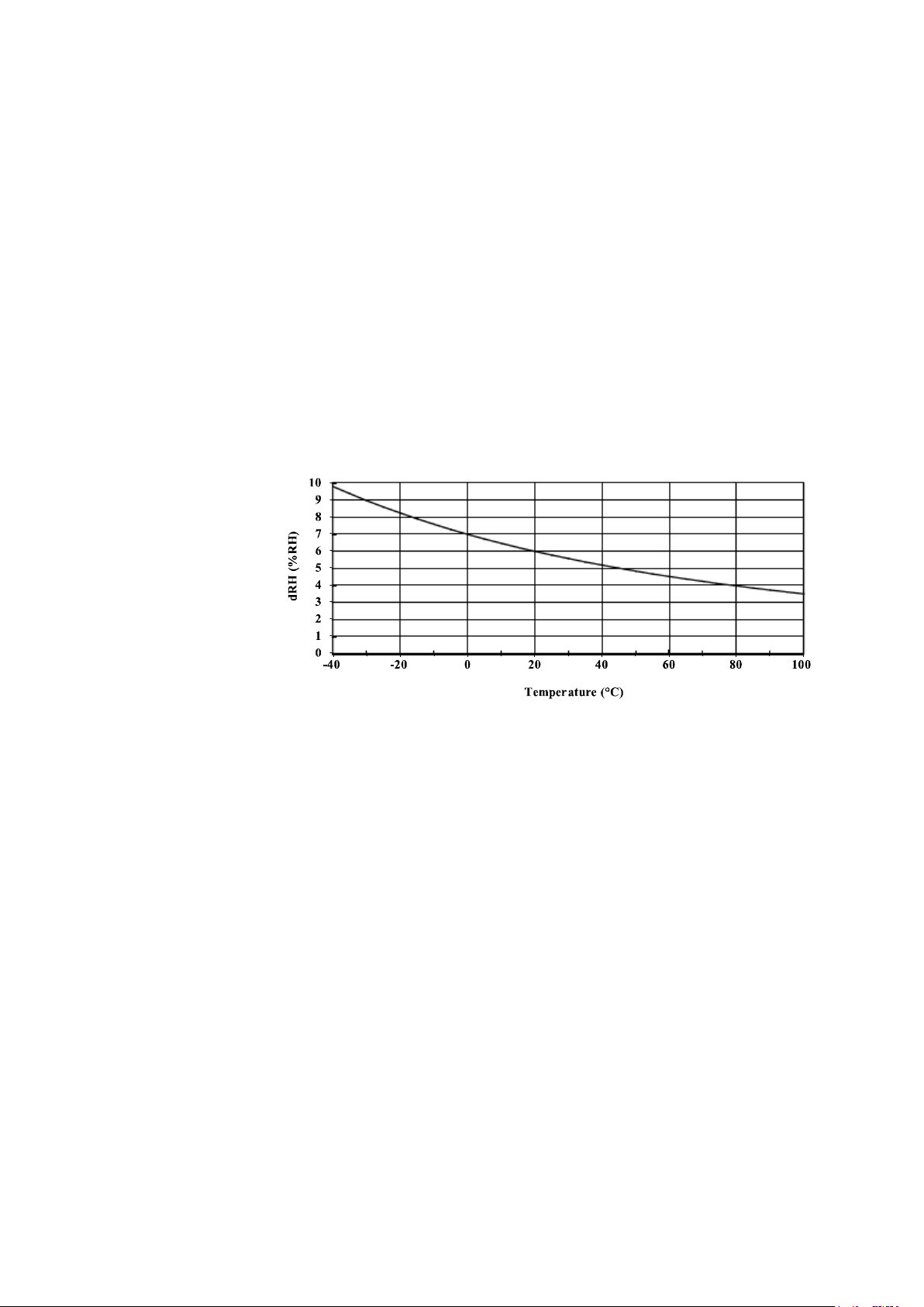
Beware of Temperature Differences
In humidity measurement and especially in calibration it is essential that
the temperature of the probe and the measuring environment is the same.
Even a small difference in temperature between the environment and the
probe causes an error. As the curve in Figure 6 below shows, if the
temperature is +20 °C and the relative humidity 100 %RH, a difference
of ±1 °C between the environment and the probe causes an error of
±6 %RH.
Figure 6 Measurement Error at 100 %RH when Difference
0507-036
Between Ambient and Sensor Temperature is 1 °C
VAISALA ________________________________________________________________________ 25
User's Guide _______________________________________________________________________
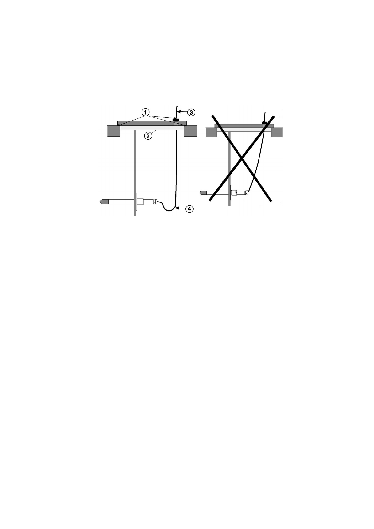
The following numbers refer to Figure 7 above:
1 = To be sealed
2 = To be insulated
3 = Insulate
4 = Let the cable hang loosely. This prevents condensed water
running to the sensor along the cable.
General Instructions for Probes with Cable
It is recommended that the probes with a cable are mounted with the
probe horizontal; this way, any water condensing on the tube cannot
flow onto the sensor.
0507-024
Figure 7 Horizontal Mounting of Probe
When there is no alternative but to install the probe in the process
vertically, the point of entry must be carefully insulated. The cable must
also be allowed to hang loosely as this prevents any condensed water
from running onto the probe along the cable.
26 ___________________________________________________________________ M210619EN-E

Chapter 3 ________________________________________________________________ Installation
The following numbers refer to Figure 8 above:
1 = To be sealed
2 = Insulate the cable
3 = To be insulated
4 = Let the cable hang loosely. This prevents condensed water
running to the sensor along the cable.
D
condensation problems caused by heat conduction along the metal.
0507-022
Figure 8 Vertical Mounting of Probe
CAUTION
o not attach a heated probe (HMT317) to metal structures to avoid
If the process temperature is much higher than that of the environment,
the whole probe and preferably a piece of the cable must be inside the
process. This prevents measuring inaccuracies caused by heat conduction
along the cable.
When mounted on the side of a duct or channel, the probe must be
inserted from the side of the duct. If this is not possible and the probe
must be inserted from the top, the point of entry must be carefully
insulated.
HMT313 for General Use
The HMT313 is a small size (d = 12mm) general-purpose probe suitable
for ducts and channels with the installation kit available from Vaisala.
The HMT313 has two probe versions for different measurement
environments:
- Probe with a flexible cable, suitable for environments up to 80 ºC
- Probe for environments up to 120 ºC
VAISALA ________________________________________________________________________ 27

User's Guide _______________________________________________________________________
The following numbers refer to Figure 9 above:
1 = Tightening cone
2 = Nut
3 = Fitting screw
4 = Sealing washer
5 = Probe; Ø 12 mm
6 = M22×1.5 or NPT 1/2"
See Appendix A on page 99 for the following probe installation kits for
HMT313 and installation examples:
- Duct mounting kit
- Cable gland
HMT314 for Pressurized Spaces
HMT314 probe is for humidity measurements in pressurized rooms and
industrial processes. The probe is provided with a nut, a fitting screw and
a sealing washer. Keep the fitting screw and nut in place on the body of
the probe during handling to prevent damage to the highly polished
surface of the probe. Follow the instructions below to achieve a leak-tight
assembly:
1. Remove the fitting screw from the nut and the probe.
2. Attach the fitting screw to the chamber wall with a sealing washer.
Tighten the fitting screw into the threaded sleeve with a torque
wrench. The tightening torque is 150 ± 10 Nm (110 ± 7 ft-lbs).
3. Insert the body of the probe into the fitting screw and attach the nut
manually to the fitting screw so that the connection feels tight.
0507-040
Figure 9 HMT314 Installation
28 ___________________________________________________________________ M210619EN-E
Chapter 3 ________________________________________________________________ Installation
When re
without increased effort.
In pressurized processes it is essential to tighten the supporting nuts and
screws very carefully to prevent loosening of the probe by the action of
pressure.
When HMT314 is installed in a process with pressure differing from
normal atmospheric pressure, enter the pressure value of the process (in
hPa or mbar) into the transmitter memory via the serial line (see
Ambient Pressure for Calculations
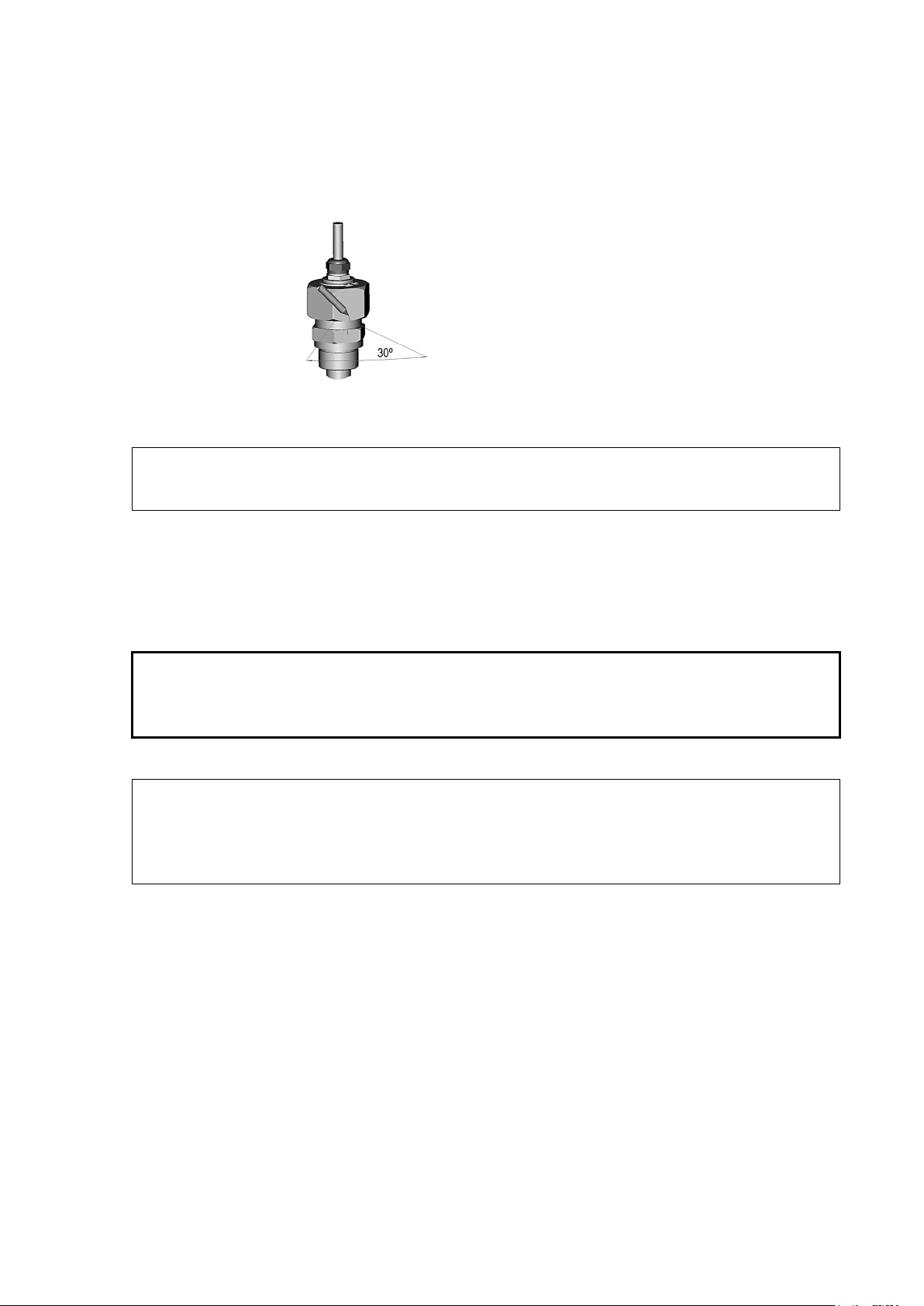
4. Mark both the fitting screw and the nut hex.
5. Tighten the nut a further 30° (1/12 turn) or if you have a torque
wrench tighten it with a torque of 80 ± 10 Nm (60 ± 7 ft-lbs).
0505-273
Figure 10 Marking the Nut
NOTE
CAUTION
NOTE
-tightening the nut after detachment the nut must be tightened
6. Clean and grease the tightening cone of the fitting screw after every
tenth detachment. Change the sealing washer every time the fitting
screw is detached. Use high-vacuum grease (for example; Down
Corning, Europe) or a similar grease.
See also section Measuring at Overpressure, on page 21.
Set
on page 51).
HMT315 for High Temperatures
HMT315 is installed similarly than the HMT313 probe but without the
supporting bar. Refer to Appendix A on page 99 for more information on
the duct installation kit for HMT315.
To avoid incorrect humidity readings, the temperature differences
between inside and outside of the duct must not be remarkable.
VAISALA ________________________________________________________________________ 29

User's Guide _______________________________________________________________________
The following numbers refer to Figure 11 above:
1 = Clasp nut; 24 mm hex nut
2 = Fitting body; 27 mm hex head
HMT317 for Demanding Processes
The HMT317 is for environments where relative humidity is very high,
near saturation. The warmed probe prevents the saturation of the sensor.
See Appendix A on page 99 for a presentation of the following probe
installation kits for HMT317 with installation examples:
- Duct mounting kit
- Cable gland
- Pressure tight Swagelok connector
HMT318 for Pressurized Pipelines
Due to the sliding fit the HMT318 is easy to install into and remove from
the pressurized process. The probe is especially suitable for the
measurements in pipelines. See section Ball Valve Installation kit for
HMT318 on page 102.
Figure 11 HMT318 Probe Dimensions (in mm)
30 ___________________________________________________________________ M210619EN-E
0507-041
Loading...