


 Loading...
M212016EN-B
User Guide
HMD60 Series Humidity and Temperature
Transmitters for Ducts in HVAC
HMD62 TMD62

PUBLISHED BY
Vaisala Oyj
Vanha Nurmijärventie 21, FI-01670 Vantaa, Finland P.O. Box 26, FI-00421 Helsinki, Finland
+358 9 8949 1
Visit our Internet pages at www.vaisala.com.
© Vaisala Oyj 2019
No part of this document may be reproduced, published or publicly displayed in any form or by any means, electronic or mechanical (including photocopying), nor may its contents be modified, translated, adapted, sold or disclosed to a third party without prior written permission of the copyright holder. Translated documents and translated portions of multilingual documents are based on the original English versions. In ambiguous cases, the English versions are applicable, not the translations.
The contents of this document are subject to change without prior notice.
Local rules and regulations may vary and they shall take precedence over the information contained in this document. Vaisala makes no representations on this document’s compliance with the local rules and regulations applicable at any given time, and hereby disclaims any and all responsibilities related thereto.
This document does not create any legally binding obligations for Vaisala towards customers or end users. All legally binding
obligations and agreements are included exclusively in the applicable supply contract or the General Conditions of Sale and General Conditions of Service of Vaisala.
This product contains software developed by Vaisala or third parties. Use of the software is governed by license terms and conditions included in the applicable supply contract or, in the absence of separate license terms and conditions, by the General License Conditions of Vaisala Group.
This product may contain open source software (OSS) components. In the event this product contains OSS components, then such OSS is governed by the terms and conditions of the applicable OSS licenses, and you are bound by the terms and conditions of such licenses in connection with your use and distribution of the OSS in this product. Applicable OSS licenses are included in the product itself or provided to you on any other applicable media, depending on each individual product and the product items delivered to you.
|
|
Table of Contents |
Table of Contents |
|
|
1. |
About This Document................................................................................... |
3 |
1.1 |
Version Information.......................................................................................... |
3 |
1.2 |
Related Manuals................................................................................................ |
3 |
1.3 |
Documentation Conventions........................................................................... |
3 |
1.4 |
Trademarks........................................................................................................ |
4 |
2. |
Product Overview........................................................................................... |
5 |
2.1 |
Introduction to HMD60 Series......................................................................... |
5 |
2.2 |
HMD62 and TMD62 Basic Features and Options.......................................... |
5 |
2.3 |
Available Parameters and Default Scaling..................................................... |
5 |
2.4 |
Connectivity to Vaisala Insight Software....................................................... |
6 |
2.5 |
Transmitter Parts............................................................................................... |
7 |
2.5.1 |
Cable Gland and Conduit Options........................................................... |
8 |
2.5.2 |
Filter Options.............................................................................................. |
8 |
2.5.3 |
Transmitter Board...................................................................................... |
9 |
2.5.4 |
Trimmers................................................................................................... |
10 |
2.5.5 |
DIP Switch Output Selection (HMD62)................................................... |
11 |
2.6 |
Filtering Factor................................................................................................. |
12 |
2.7 |
Environmental Compensation (HMD62)....................................................... |
12 |
3. |
Installation........................................................................................................ |
13 |
3.1 |
Transmitter Dimensions.................................................................................. |
13 |
3.2 |
Duct Mounting Overview................................................................................ |
14 |
3.3 |
Installing into Duct.......................................................................................... |
15 |
3.4 |
Wiring............................................................................................................... |
16 |
4. |
Calibration and Adjustment...................................................................... |
18 |
4.1 |
Calibration and Adjustment Overview.......................................................... |
18 |
4.2 |
Calibration and Adjustment Using Trimmers............................................... |
18 |
4.2.1 |
1-Point Adjustment Using Trimmers and Reference Calibrator.......... |
19 |
4.2.2Adjusting Output Using Trimmers and Reference
|
Transmitter (1-point adjustment)........................................................... |
19 |
4.2.3 |
Resetting Trimmers Back to Zero......................................................... |
20 |
4.3 |
Calibration and Adjustment with Insight PC Software............................... |
21 |
4.3.1 |
2-Point Adjustment with Insight and Reference Calibrator............... |
22 |
4.3.2 |
1-Point Adjustment with Insight and Reference Transmitter............. |
23 |
4.4 |
Calibration and Adjustment with MI70 Hand-Held Indicator................... |
24 |
4.4.1 |
1-Point Adjustment Using Reference Environment............................. |
24 |
5. |
Operating with Insight PC Software..................................................... |
27 |
5.1 |
Vaisala Insight Software................................................................................. |
27 |
5.2 |
Connecting to Insight Software.................................................................... |
27 |
5.3 |
Insight Main View............................................................................................ |
28 |
5.3.1 |
Basic and Advanced User Modes.......................................................... |
29 |
5.4 |
Configuring Analog Outputs with Insight................................................... |
29 |
5.4.1 |
Testing and Adjusting Analog Output Current (mA) Level............... |
30 |
1
HMD62 TMD62 User Guide |
M212016EN-B |
5.5 |
Configuring Minimum and Maximum RH and T Errors with Insight |
..........31 |
5.6 |
Changing Pressure Compensation Settings with Insight (HMD62)......... |
33 |
5.7 |
Setting Filtering Factor with Insight............................................................ |
34 |
6. |
Operating with MI70 Indicator................................................................ |
35 |
6.1 |
Overview of MI70 Support............................................................................ |
35 |
6.1.1 |
MI70 Indicator Parts................................................................................ |
35 |
6.2 |
Connecting HMD60 to MI70 Indicator......................................................... |
36 |
6.3 |
Basic Display................................................................................................... |
37 |
6.4 |
Graphical Display............................................................................................ |
37 |
6.5 |
Main Menu....................................................................................................... |
38 |
6.6 |
Holding and Saving the Display.................................................................... |
38 |
6.7 |
Recording Data............................................................................................... |
39 |
7. |
Maintenance and Troubleshooting....................................................... |
40 |
7.1 |
Cleaning.......................................................................................................... |
40 |
8. |
Technical Data................................................................................................. |
41 |
8.1 |
Specifications................................................................................................... |
41 |
8.2 |
Spare Parts and Accessories......................................................................... |
43 |
8.3 |
Transmitter Dimensions................................................................................. |
44 |
Warranty............................................................................................................ |
45 |
|
Technical Support........................................................................................... |
45 |
|
Recycling........................................................................................................... |
45 |
|
2
Chapter 1 – About This Document
1. About This Document
1.1 Version Information
Table 1 Document versions
Document Code |
Date |
Description |
|
|
|
M212016EN-B |
May 2019 |
This manual. Added information about short probe option |
|
|
and the HMD65 transmitter model, updated the |
|
|
information on the e…ect of DIP switch parameter |
|
|
selection on Insight configuration. Corrected filtering |
|
|
factor formula. Stability specification corrected, lead- |
|
|
through and plug appearance updated in illustrations. |
|
|
|
M212016EN-A |
September 2018 |
First version of the document. |
|
|
|
1.2 Related Manuals
Table 2 Related Manuals
Document Code |
Description |
|
|
M212049EN |
HMD62 and TMD62 Multilingual Quick Guide (languages: English, |
|
German, French, Spanish, Portuguese, Russian, Chinese, Japanese) |
|
|
M212243EN |
HMD65 User Guide in English |
|
|
M212264EN |
HMD65 Multilingual Quick Guide (languages: English, German, |
|
French, Spanish, Portuguese, Russian, Chinese, Japanese) |
|
|
1.3 Documentation Conventions
WARNING! alerts you to a serious hazard. If you do not read and follow instructions carefully at this point, there is a risk of injury or even death.
CAUTION! warns you of a potential hazard. If you do not read and follow instructions carefully at this point, the product could be damaged or important data could be lost.
3

HMD62 TMD62 User Guide |
M212016EN-B |
Note highlights important information on using the product.
Tip gives information for using the product more e‡ciently.
1.4 Trademarks
Vaisalaâ and HUMICAPâ are registered trademarks of Vaisala Oyj.
Windowsâ is either a registered trademark or trademark of Microsoft Corporation in the United States and other countries.
All other product or company names that may be mentioned in this publication are trade names, trademarks, or registered trademarks of their respective owners.
4
Chapter 2 – Product Overview
2. Product Overview
2.1 Introduction to HMD60 Series
The duct mounted HMD60 HUMICAPâ Humidity and Temperature Transmitters are designed for monitoring humidity and temperature in demanding HVAC and light industrial applications. HMD60 series transmitters provide stable, reliable, and highly accurate (up to ±1.5 %RH and ±0.1 °C (0.18 °F)) measurements, and are resistant to chemicals and dust.
HMD60 series transmitter options include 2 analog output models: HMD62 for measuring both humidity and temperature, and TMD62 for temperature measurements. Both HMD62 and TMD62 use 4 ... 20 mA loop powered current output. The HMD65 transmitter model includes both analog and digital output options.
Thanks to easy access to electronics also when the transmitter is installed to a duct, configuration and adjustment can be carried out quickly and conveniently. Available configuration and adjustment interface options range from physical trimmers and DIP switches on the transmitter's circuit board to Vaisala Insight PC software for Windowsâ.
2.2 HMD62 and TMD62 Basic Features and Options
•Measurement options:
•HMD62 for humidity and temperature measurement
•TMD62 for temperature measurement
•Humidity parameters available as output options in HMD62: RH, Td, Tdf, A, X, Tw, H
•Analog output: 4 ... 20 mA, loop powered
•HMD62: 2 analog output channels for humidity and temperature measurements
•TMD62: 1 analog output channel for temperature measurement
•Power supply input: 10 ... 35 VDC / 20 ... 35 VDC
•Configuration and adjustment options:
•RH and T measurement field adjustment with trimmers
•Humidity output parameter selection with DIP switches (HMD62)
•Field adjustment with MI70 hand-held indicator
•Configuration and adjustment with Vaisala Insight PC software
2.3 Available Parameters and Default Scaling
HMD62 Measurement Parameters and Default Analog Output
Scaling
Table 3 (page 6) shows the available output parameters and the default analog output scaling of the parameters for HMD62.
5
HMD62 TMD62 User Guide |
|
M212016EN-B |
Table 3 HMD62 Measurement Parameters and Default Scaling |
||
|
|
|
Parameter |
Default Scaling for 4 … 20 mA Output Range |
|
|
|
|
Relative humidity (RH) |
0 |
… 100 %RH |
|
|
|
Temperature (T) |
-20 ... +80 °C (-4 ... +176 °F) |
|
|
|
|
Dew point temperature (Td) |
-40 ... +80 °C (-40 ... +176 °F) |
|
Dew point/frost point |
-40 ... +80 °C (-40 ... +176 °F) |
|
temperature (Tdf) |
|
|
Absolute humidity (A) |
0 |
… 300 g/m3 (0 … 131.1 gr/ft3) |
Mixing ratio (X) |
0 |
… 600 g/kg (0 … 4200 gr/lb) |
|
|
|
Wet-bulb temperature (Tw) |
-40 ... +80 °C (-40 ... +176 °F) |
|
Enthalpy (H) |
-40 … 1600 kJ/kg (-9.5 ... 695.6 Btu/lb) |
|
|
|
|
TMD62 Measurement Parameters and Default Analog Output
Scaling
Table 4 (page 6) shows the available output parameters and the default analog output scaling of the parameters for TMD62.
Table 4 TMD62 Measurement Parameters and Default Scaling
Parameter |
Default Scaling for 4 … 20 mA Output Range |
|
|
Temperature (T) |
-20 ... +80 °C (-4 ... +176 °F) |
|
|
Changing Measurement Parameter Scaling
If your application requires an analog output scaling that di…ers from the defaults shown in Table 3 (page 6) and Table 4 (page 6), you can configure the scaling by connecting the transmitter to Vaisala Insight PC software (requires Vaisala USB cable 219690).
2.4 Connectivity to Vaisala Insight Software
The transmitter can be connected to Vaisala Insight software using a Vaisala USB cable (order code 219690). With the Insight software, you can:
•Calibrate and adjust the measurement.
•See device information and status.
•See real-time measurement.
•Configure output parameters and scaling.
6
Chapter 2 – Product Overview
More Information
Connecting to Insight Software (page 27)
2.5 Transmitter Parts
1
2
3 |
4
5 |
6 |
7 |
9
8 |
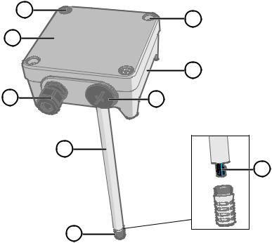
Figure 1 HMD62 and TMD62 Transmitter Parts Overview
1Captive screw (2 pcs, cross-head) for attaching the lid of the transmitter.
2Screw (2 pcs) for mounting the transmitter on the installation surface.
3Transmitter lid. Open the captive screws of the lid to access input and output electronics.
4Transmitter base. Contains the input and output connectors on the transmitter board: see Transmitter Board (page 9).
5Cable gland (M16 x 1.5 lead-through) for leading wires into the transmitter.
6Alternative lead-through (M20 x 1.5) for wiring.
7Probe body. Long (shown) and short probe options available: see Transmitter Dimensions (page 13).
8Probe filter (default option: AISI 316L stainless steel).
9HUMICAPâ sensor inside the probe filter.
7
HMD62 TMD62 User Guide |
M212016EN-B |
CAUTION! Do not touch the sensor element.
2.5.1 Cable Gland and Conduit Options
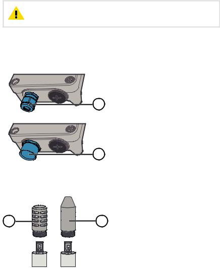
HMD60 has 2 lead-throughs (M16x1.5 and M20x1.5) that can be used with a variety of cable gland and conduit options. Figure 2 (page 8) shows the cable gland and conduit options available from Vaisala.
1
2
2.5.2 Filter Options
Figure 2 HMD60 Cable Gland and Conduit Options
1Cable Gland and O-ring M16 x 1.5 (Vaisala order code: 254280SP). This is the default option delivered with HMD60.
2Conduit fitting and O-ring (M16x1.5 / NPT1/2") (Vaisala order code: 210675SP).
Figure 3 (page 8) shows the filter options available for HMD60.
1 |
2 |
Figure 3 HMD60 Filter Options
1Metal Grid with PTFE Membrane (Vaisala order code ASM212652SP). This is the default option delivered with HMD60.
2Sintered Filter (Vaisala order code HM46670SP).
8

Chapter 2 – Product Overview
2.5.3 Transmitter Board
2
3
1
4 |
5
6
Figure 4 HMD60 Transmitter Board: Service Port, DIP switches, Trimmers and Screw Terminals
1Service port for MI70 hand-held indicator and Insight PC software cable connection.
2DIP switches for humidity parameter selection (HMD62).
3Trimmer for humidity measurement adjustment (HMD62).
4Screw terminals for humidity measurement output (HMD62).
5Screw terminals for temperature measurement output.
6Trimmer for temperature measurement adjustment.
The HMD62 board (shown in Figure 4 (page 9)) includes options for both humidity and temperature output. The TMD62 board includes only components limited to temperature output options. See Wiring (page 16) for more information.
9
HMD62 TMD62 User Guide |
M212016EN-B |
2.5.4 Trimmers
|
Figure 5 Component Board Adjustment |
|
|
Trimmer |
|
1 |
1 Use a Phillips head screwdriver (PH0) |
|
to rotate the RH or T adjustment |
||
|
||
|
trimmer. To increase the measurement |
|
|
output value, rotate the trimmer |
|
|
clockwise. To decrease, rotate |
|
|
counterclockwise. |
|
|
Note that there is a slight delay before |
|
|
the measurement output changes |
|
|
after rotating the trimmer. |
You can adjust the transmitter's RH (HMD62) or T (HMD62 and TMD62) measurement output with the trimmers on the component board. During trimmer adjustment, the output of the transmitter is corrected using the trimmers until the output matches the known value of a reference.
HMD62: −5 %RH ... +5 %RH |
TMD62, HMD62: −0.3 °C ... +0.3 °C |
||
±0 %RH |
±0 °C |
||
−1 %RH |
+1 %RH |
−0.06 °C |
+0.06 °C |
−2 %RH |
+2 %RH |
−0.12 °C |
+0.12 °C |
−3 %RH |
+3 %RH |
−0.18 °C |
+0.18 °C |
−4 %RH |
+4 %RH |
−0.24 °C |
+0.24 °C |
−5 %RH |
+5 %RH |
−0.3 °C |
+0.3 °C |
|
RH |
|
T |
Figure 6 RH and T Trimmer Adjustment Ranges (Indicative)
You can only calibrate the relative humidity measurement (RH) and temperature measurement (T). Other parameters (available for HMD62) are calculated internally based on RH and T. Check that the output selection DIP switch is set to RH when making adjustments with the physical trimmer; when using the Insight PC software, set all DIP switches to the OFF position.
CAUTION! If you use the Insight PC software to adjust the measurement or to restore the factory settings, always return the physical trimmer to the middle position before starting. When you make an adjustment with Insight, the position in which the trimmer is at that point is set as the ±0 point.
10
Chapter 2 – Product Overview
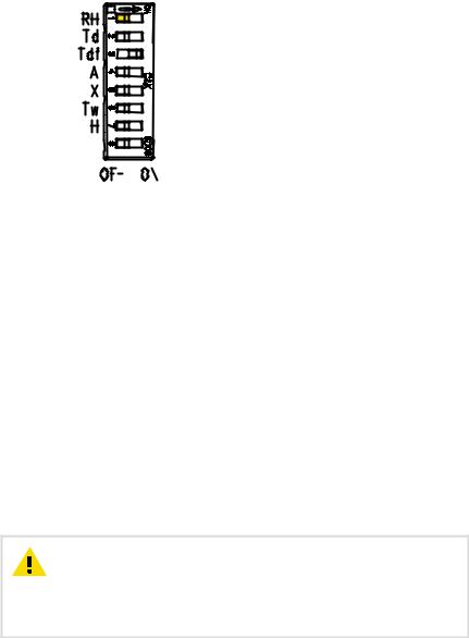
2.5.5 DIP Switch Output Selection (HMD62)
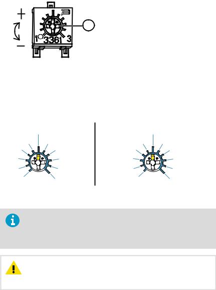
Figure 7 HMD62 DIP Switch Example: Tdf
Output Selected
|
|
|
|
|
|
|
RH |
Relative humidity |
|
|
|
|
|
|
|
||
|
|
|
|
|||||
|
|
|
|
|
|
|
Td |
Dew point temperature |
|
|
|
|
|
|
|
Tdf |
Dew point/frost point temperature |
|
|
|
|
|||||
|
|
|
|
|
|
|
A |
Absolute humidity |
|
|
|
|
|||||
|
|
|
|
|||||
|
|
|
|
|
|
|
X |
Mixing ratio |
|
|
|
|
|||||
|
|
|
|
|
|
|
Tw |
Wet-bulb temperature |
|
|
|
|
|
|
|
H |
Enthalpy |
|
|
|
|
|||||
|
|
|
|
|
|
|
|
|
|
|
|
|
|
|
|
|
|
|
|
|
|
|
|
|
|
|
You can change the humidity parameter that is output on the RH channel of HMD62 with the DIP switches on the component board. Select the parameter you want the transmitter to output by sliding the parameter's DIP switch to the right (ON). In the example in Figure 7 (page 11), the transmitter's selected output parameter is dew point/frost point temperature (Tdf). Keep the other DIP switches in the OFF position (left).
The selected parameter uses the default scaling shown in Table 5 (page 11).
Table 5 HMD62 Default Parameter Scaling
Parameter |
Default Scaling for 4 … 20 mA Output Range |
||||
|
|
|
|
||
RH |
0 |
… 100 %RH |
|
||
|
|
|
|
||
Td |
-40 ... +80 |
°C (-40 |
... +176 °F) |
||
Tdf |
-40 ... +80 |
°C (-40 |
... +176 °F) |
||
A |
0 |
… 300 g/m3 (0 … 131.1 gr/ft3) |
|||
X |
0 |
… 600 g/kg (0 … 4200 gr/lb) |
|||
|
|
|
|
|
|
Tw |
-40 |
... +80 |
°C (-40 |
... +176 °F) |
|
H |
-40 |
… 1600 kJ/kg (-9.5 ... 695.6 Btu/lb) |
|||
|
|
|
|
|
|
CAUTION! Note that the humidity output parameter selected with the DIP switches on the transmitter component board will be used instead of the parameter selected with Insight. When using Insight to configure the output, set all humidity parameter selection DIP switches on the transmitter component board to the OFF position (left) to ensure they do not cause a conflict with the Insight settings.
11

HMD62 TMD62 User Guide |
M212016EN-B |
HMD62 only:If you use Insight to set both analog output channels to output T measurement, the humidity parameter DIP switches do not have an e…ect on the output.
2.6 Filtering Factor
If the measuring environment produces occasional exceptionally high or low readings that need to be averaged out in the output, you can apply a filtering factor to the RH or T output (filtering factor range: 0.001 … 1.000). The filtering factor defines the speed at which the latest measurement is integrated into the transmitter's output. By default, the filtering factor is set to 0.500, which means that the displayed output is a 50%+50% combination of the previous measurement and the most recent measurement. To show the latest measurement directly in the output, set the filtering factor to 1.000 (no filtering).
The following formula is used when calculating the output:
output = [(new (unfiltered) measurement × filtering factor) + (previous output × (1.0 - filtering factor))]
The filtering factor can be configured with the Insight PC software.
More Information
Setting Filtering Factor with Insight (page 34)
2.7 Environmental Compensation (HMD62)
By default, the pressure value used in HMD62 measurement calculation is 1013.2 hPa. If the pressure of your measurement environment di…ers from this, you can configure the transmitter's pressure compensation value with the Insight PC software.
More Information
Changing Pressure Compensation Settings with Insight (HMD62) (page 33)
12
3. Installation
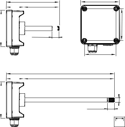
3.1 Transmitter Dimensions
The dimensions are given in millimeters and [inches].
101 [3.97]
|
149 [5.87] |
|
49 [1.92] |
|
100 [3.94] |
|
||
|
|
|
19.5 [0.77]

 Ø 12 [0.47]
|
299 [11.77] |
|
49 [1.92] |
|
250 [9.84] |
|
||
|
|
|
101 [3.97]
Figure 8 Dimensions with Long and Short Probe
Chapter 3 – Installation
101 [3.97] |
23].82[3 |
82 [3.23] |
19.5 [0.77] |
Ø 12 [0.47] |
|
|
|
mm |
|
[in] |
13
Loading...