


 Loading...
USER'SGUIDE
VaisalaHMDW110SeriesHumidityand
TemperatureTransmitters
M211726EN-A
PUBLISHED BY
Vaisala Oyj
Streetaddress: Vanha Nurmijärventie 21,FI-01670 Vantaa,Finland Mailing address: P.O. Box 26,FI-00421 Helsinki,Finland
Phone: |
+358 |
9 8949 1 |
Fax: |
+358 |
9 8949 2227 |
Visitour Internetpages at www.vaisala.com.
© Vaisala 2014
No partofthis manual may be reproduced,published or publicly displayed in any form or by any means,electronic or mechanical (including photocopying), nor may its contents be modified,translated,adapted,sold or disclosed to a third party withoutprior written permission ofthe copyrightholder. Translated manuals and translated portions ofmultilingual documents are based on the original English versions. In ambiguous cases,the English versions are applicable,notthe translations.
The contents ofthis manual are subjectto change withoutprior notice.
This manual does notcreate any legally binding obligations for Vaisala towards customers or end users. All legally binding obligations and agreements are included exclusively in the applicable supply contractor the General Conditions ofSale and General Conditions ofService ofVaisala.

Table of Contents
1 General Information |
3 |
AboutThis Document |
3 |
Documentation Conventions |
3 |
Safety |
4 |
ESD Protection |
4 |
Recycling |
4 |
Trademarks |
4 |
Software License |
5 |
Warranty |
5 |
2 ProductOverview |
6 |
HMDW110 Series Overview |
6 |
OutputParameters Explained |
7 |
HMD110/112 Parts |
8 |
HMW110/112 Parts |
9 |
HMS110/112 Parts |
10 |
ComponentBoard |
11 |
Analog OutputOverrange Behavior |
12 |
3 Installation |
13 |
Selecting Location |
13 |
HMD110/112 Installation |
14 |
HMW110/112 Installation |
16 |
HMS110/112 Installation |
17 |
Wiring HMDW110 |
19 |
Wiring Both CurrentLoops With a Single Power Supply |
20 |
HMDW110 Power Supply Requirements |
20 |
Wiring HMDW110 with RDP100 |
21 |
4 Service Port |
22 |
Connecting to the Service Port |
22 |
Terminal Application Settings |
23 |
Serial Commands |
24 |
Device Information and Status |
25 |
Serial Line Outputand Communication |
28 |
MeasurementOutput |
28 |
MeasurementOutputFormat |
29 |
Serial Line Communication |
31 |
Analog output |
33 |
Calibration and AdjustmentCommands |
36 |
Other Commands |
39 |
1

5 Maintenance |
41 |
Cleaning |
41 |
Calibration and Adjustment |
41 |
AdjustmentTypes |
42 |
AdjustmentPoints |
42 |
Calibration and AdjustmentUsing a Hand-Held Meter and a |
|
Reference Probe |
43 |
One-PointHumidity Calibration and AdjustmentUsing a Hand-Held |
|
Meter and HMK15 Humidity Calibrator |
45 |
Two-PointHumidity Calibration and Adjustmentusing a computer |
|
and a HMK15 Humidity Calibrator |
46 |
Two-PointTemperature Calibration and Adjustmentusing a |
|
Computer |
49 |
Replacing the HUMICAP® Sensor on HMD110/112 and |
|
HMW110/112 |
51 |
Replacing the HUMICAP® Sensor on HMS110/112 |
52 |
5 Troubleshooting |
54 |
Error Messages |
54 |
Technical Support |
55 |
Productreturns |
55 |
6 Technical Data |
56 |
Specifications |
56 |
Dimensions |
58 |
Spare Parts and Accessories |
59 |
2
1GeneralInformation
1 GENERAL INFORMATION
About This Document
This documentprovides information for installing,operating,and maintaining HMDW110 series transmitters.
Table 1 Version Information |
|
Document Code |
Description |
M211726EN-A |
Thisdocument.July2014.Firstversion. |
Table 2 Related Documents |
|
Document Code |
Description |
M211692EN |
HMDW110SeriesQuickGuide |
M210297EN |
HM70User'sGuide |
M210185EN |
HMK15User'sGuide |
M211691EN |
RDP100User'sGuide |
Documentation Conventions
Warnings alertyou to a serious hazard. Ifyou do notread and follow instructions very carefully atthis point,there is a risk of injury or even death.
Cautions warn you ofa potential hazard. Ifyou do notread and follow instructions carefully atthis point,the productcould be damaged or importantdata could be lost.
Notes highlightimportantinformation on using the product.
3
1GeneralInformation
Safety
The HMDW110 series transmitter delivered to you has been tested for safety and approved as shipped from the factory. Note the following precautions:
Do notmodify the unit. Improper modification can damage the productor lead to malfunction.
ESD Protection
Electrostatic Discharge (ESD) can cause immediate or latentdamage to electronic circuits. Vaisala products are adequately protected againstESD for their intended use. Itis possible to damage the product,however,by delivering electrostatic discharges when touching,removing,or inserting any objects inside the equipmenthousing.
To make sure you are notdelivering high static voltages yourself,avoid touching exposed componentcontacts during installation and maintenance.
Recycling
Recycle all applicable material.
Dispose ofthe unitaccording to statutory regulations. Do not dispose ofwith regular household refuse.
Trademarks
HUMICAP® is a registered trademark ofVaisala Oyj.
Windows® is a registered trademark ofMicrosoftCorporation.
All other trademarks referred to are the property oftheir respective owners.
4

1GeneralInformation
Software License
This productcontains software developed by Vaisala. Use ofthe software is governed by license terms and conditions included in the applicable supply contractor,in the absence ofseparate license terms and conditions,by the General License Conditions ofVaisala Group.
Warranty
Visitour Internetpages for more information and our standard warranty terms and conditions: www.vaisala.com/warranty.
Please observe thatany such warranty may notbe valid in case ofdamage due to normal wear and tear,exceptional operating conditions,negligenthandling or installation,or unauthorized modifications. Please see the applicable supply contractor Conditions ofSale for details ofthe warranty for each product.
5

2Product Overview
2 PRODUCT OVERVIEW
HMDW110 Series Overview
HMDW110 series transmitters are accurate humidity and temperature transmitters for measurements in HVAC and cleanroom applications. The series consists ofthe following models:
nHMD110/112 models for installation in ventilation ducts
nHMW110/112 models for wall installation
nHMS110/112 models for outdoor use
All models are loop-powered,with 2-wire currentoutputs for humidity and temperature. HMD112,HMW112,and HMS112 are standard models. HMD110, HMW110,and HMS110 are factory configurable models thatare delivered with customer specific outputsettings,including calculated humidity parameters and special scaling ofoutputs.
HMDW110 series transmitters can be connected to Vaisala’s RDP100 panel display for real-time viewing ofthe measurements. HMDW110 series can also supply the operating power to the display using only the loop power from the outputs.
6

2Product Overview
Output Parameters Explained
HMDW110 series transmitters offer several outputparameters. Relative humidity (RH) and temperature (T) are the measured parameters,the others are calculated based on RH and T.
Table 3 HMDW110 Series Output Parameters
Parameter |
Symbol |
Units |
Description |
|
Temperature |
T |
°C |
TemperatureinCelsiusorFahrenheitscale. |
|
|
|
|
°F |
|
Relative |
RH |
% |
Ratioofthepartialpressureofwatervaporintheairto |
|
humidity |
|
|
thesaturationvaporpressureofairatcurrent |
|
|
|
|
|
temperature. |
Dewpoint |
Td/f |
°C |
Temperatureatwhichthewatervaporintheairwill |
|
|
|
|
°F |
condenseintowateratthecurrentpressure.Whenthe |
|
|
|
|
dewpointisbelow 0°C,thetransmitteroutputsfrostpoint |
|
|
|
|
(Tf)insteadofdewpoint. |
Enthalpy |
h |
kJ/kg |
Sumoftheinternalenergyofa thermodynamicsystem. |
|
|
|
|
BTU/lb |
|
Wetbulb |
Tw |
°C |
Theminimum temperaturethatcanbereachedby |
|
temperature |
|
°F |
evaporativecoolinginthecurrentconditions. |
|
|
|
|
|
|
Check the type label on your transmitter to verify its output parameters and scaling ofthe outputchannels.
7
2Product Overview
HMD110/112 Parts
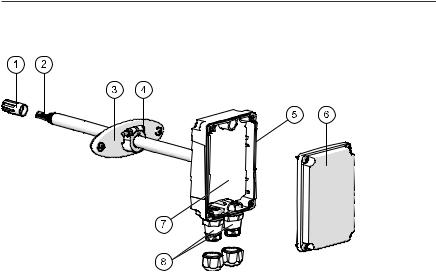
Figure 1 HMD110/112 Parts
1= PTFE membrane filter.
2= Sensors for humidity and temperature. 3= Fastening flange.
4= Tightening screw for fastening flange. 5= Type label.
6= Transmitter cover.
7= Componentboard. See ComponentBoard on page 11. 8= Cable glands for 4 ... 8 mm diameter cable.
8
2Product Overview
HMW110/112 Parts
Figure 2 HMW110/112 Parts
1= Screw holes for mounting (2 pcs). 2= Cable gland.
3= Sensors for humidity and temperature. 4= PTFE filter.
5= Type label.
6= Componentboard. See ComponentBoard on page 11. 7= Probe.
8= Transmitter cover with captive screws.
9
2Product Overview
HMS110/112 Parts
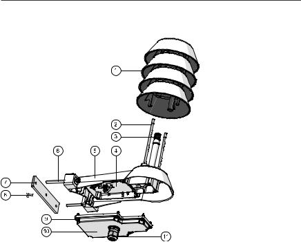
Figure 3 HMS110/112 Parts
1= Radiation shield. Do notremove for installation,only when replacing the sensor or filter.
2= Long screws thatkeep the radiation shield in place (2 pcs), 3 mm hex socket.
3= Sensors for humidity and temperature under PTFE membrane filter. 4= Componentboard. See ComponentBoard on the facing page. 5= Transmitter body.
6= Screws for pole mounting (2 pcs,medium size Pozidriv).
7= Clamp for pole mounting. The holes are threaded for the included pole mounting screws and setscrew.
8= Setscrew (medium size Pozidriv). Install after pole mounting to stop the transmitter from turning.
9= Medium size crosshead screws (6 pcs). 10= Transmitter cover.
11= Cable gland. Suitable for 4 ... 8 mm diameter cable.
10
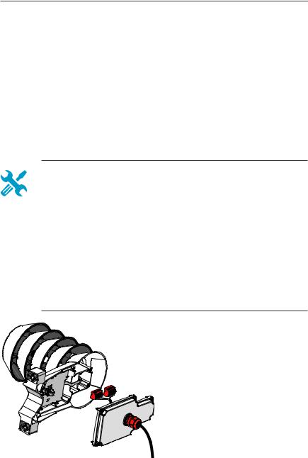
2Product Overview
Component Board
All HMDW110 transmitter models use the same componentboard and have two 4 ... 20 mA outputs (loop powered). There is also a service portfor configuration and calibration use.
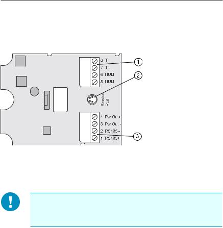
Figure 4 HMDW110 Series Component Board
1= Terminal block for 4 ... 20 mA currentloop outputs. 2= Service portconnector (4-pin M8).
3= Terminal block for RS-485 outputto RDP100 display panel (optional).
You can pull outthe terminal blocks from the componentboard for easier installation,and to disconnectthe transmitter from power and RS-485 when using the service port.
11

2Product Overview
Analog Output Overrange Behavior
Analog outputs ofthe HMDW100 series transmitters have a defined behavior when the values measured by the transmitter are outside the scaled analog outputrange:
nOutputis clipped atthe end ofthe scaled outputrange.
nYou can allow the outputexceed the scaled range by 10% with the aover serial command.
nOutputis setto error state (default3.6 mA) ifan error is active (for example, due to sensor damage). You can change the error state using the aerr command.
For configuration ofthe analog outputs using serial commands,see section Analog outputon page 33.
12

3Installation
3 INSTALLATION
Selecting Location
When mounting ductmodel transmitters:
nAvoid installing in a location where condensation may fall on the sensor inside the duct.
nPosition the sensor in the center ofthe duct.
nSelecta site where the transmitter can be installed horizontally,onto the side ofthe duct. Do notpointthe probe downward,as this will make condensation run down to the sensor.
When mounting wall model transmitters:
nSelecta location thatrepresents well the area ofinterest.
nDo notinstall on the ceiling.
nAvoid placing the transmitter near heatand moisture sources,close to the discharge ofthe supply air ducts,and in directsunlight.
When mounting outdoor transmitters:
nInstall in a location with a good airflow around the transmitter.
nAvoid placing the transmitter near windows,air conditioning units,or other heatand moisture sources such as cooling towers.
nInstall the transmitter atleast2.5 m above ground level.
13
3Installation
HMD110/112 Installation
nMedium size crosshead screwdriver (Pozidriv) for screws on cover and flange.
nSmall slotted screwdriver for screw terminals.
nDrill with 2.5 mm and 13 mm bits for making the installation holes.
nTools for cutting and stripping wires.
n19 mm open-end wrench for tightening the cable gland.
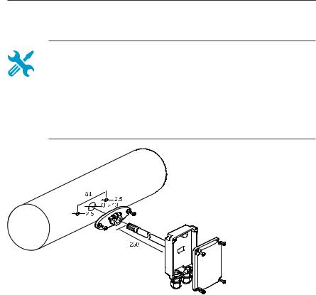
Figure 5 HMD110/112 Installation
1.Remove the yellow transportprotection cap and separate the fastening flange from the transmitter.
2.Use the flange to mark the location and size ofthe installation holes on the side ofthe duct.
3.Drill the installation holes in the duct. Secure the fastening flange to the duct with the two screws (included).
14
3Installation
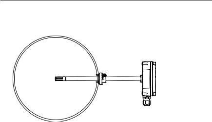
4.Push the probe ofthe transmitter through the flange and into the duct.The probe should reach far enough so thatthe sensor is located in the middle of the duct.
Figure 6 HMD110/112 Centering Inside Duct
5.Secure the transmitter to the flange by tightening the screw on the flange thatholds the probe in place.
6.Open the transmitter cover,and route the cables through the cable glands. Connectthe wires to the screw terminals according to the wiring instructions:
o |
Wiring HMDW110 on page 19 |
o |
Wiring HMDW110 with RDP100 on page 21 |
For the arrangementofthe screw terminals,see section ComponentBoard on page 11.
7. Tighten the cable gland(s) and close the transmitter cover.
15
3Installation
HMW110/112 Installation
nMedium size crosshead screwdriver (Pozidriv) for cover screws.
nSmall slotted screwdriver for screw terminals.
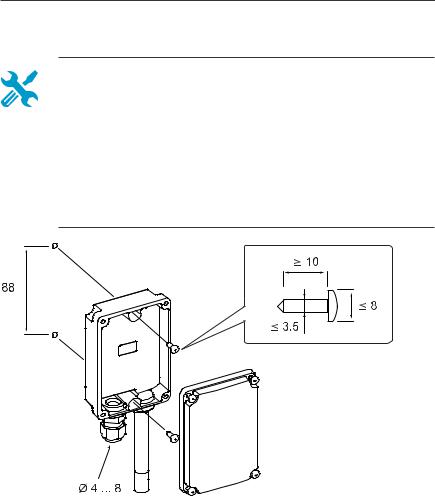
nTwo installation screws:Ø≤ 3.5 mm,head Ø ≤ 8 mm.
nDepending on the wall material and screw type,you may need a drill and a suitable drill bitto make installation holes for screws.
nTools for cutting and stripping wires.
n19 mm open-end wrench for tightening the cable gland.
Figure 7 HMW110/112 Installation
1.Open the transmitter cover and use two screws (notincluded) to attach the transmitter to the wall. The probe and cable gland should pointdown.
16
3Installation
2.Open the transmitter cover,and route the cable through the cable gland. Connectthe wires to the screw terminals according to the wiring instructions:
o |
Wiring HMDW110 on page 19 |
o |
Wiring HMDW110 with RDP100 on page 21 |
For the arrangementofthe screw terminals,see section ComponentBoard on page 11.
3.Tighten the cable gland and close the transmitter cover.
4.Remove the yellow transportprotection cap from the probe.
HMS110/112 Installation
nMedium size crosshead screwdriver (Pozidriv).
nSmall slotted screwdriver for screw terminals.
nTools for cutting and stripping wires.
n19 mm open-end wrench for tightening the cable gland.
Additional tools for pole installation:
nZip ties for securing the cable to the pole. Additional tools for wall installation:
nDrill and bits.
nScrews (2 pcs,Ø< 5.5 mm) and wall plugs.
nCable clips for securing the cable to the wall.
1. Open the six screws thathold the transmitter cover.
2. Route the power and signal cable through the cable gland,and connectthe wires to the screw terminals according to the wiring instructions:
o |
Wiring HMDW110 on page 19 |
o |
Wiring HMDW110 with |
|
RDP100 on page 21 |
For the arrangementofthe screw terminals,see section ComponentBoard on page 11.
17
Loading...