


HMP230
Table of contents
 Loading...
HMP230 Series Transmitters
USER'S GUIDE
M210225en-B
May 2002

PUBLISHED BY
Vaisala Oyj Phone : (+358 9) 894 91
P.O. Box 26 Fax: (+358 9) 8949 2227
FIN-00421 Helsinki
Finland
Visit our Internet pages at http://www.vaisala.com/
© Vaisala 2002
No part of this manual may be reproduced in any form or by any
means, electronic or mechanical (including photocopying), nor may its
contents be communicated to a third party without prior written
permission of the copyright holder.
The contents are subject to change without prior notice.

HMP230 SERIES
M210225en-B User's Guide
Contents
1. PRODUCT DESCRIPTION................................................................................................... 1
2. TO BE NOTED WHEN MEASURING HUMIDITY.................................................................. 3
3. INSTALLATION ................................................................................................................... 4
3.1. Selecting the place of installation .......................................................................... 4
3.2. Mounting ................................................................................................................. 5
3.2.1. Mounting the HMP231................................................................................ 5
3.2.2. Installing the HMP233, HMP234 and HMP235............................................ 5
3.2.3. HMP233 transmitter...................................................................................6
3.2.4. HMP234 transmitter...................................................................................7
3.2.5. HMP235 transmitter................................................................................. 10
3.2.6. HMP237 transmitter................................................................................. 11
3.2.7. HMP238 transmitter................................................................................. 12
3.2.7.1. Mounting; overview.................................................................................. 13
3.2.7.2. Installing the probe through the ball valve assembly................................. 16
3.3. Grounding ............................................................................................................. 20
3.4. Electrical connections .......................................................................................... 22
3.4.1. Connection to a 24 VAC supply ................................................................ 23
4. COMMISSIONING.............................................................................................................. 24
4.1. Changing the parameters ..................................................................................... 24
4.2. Security lock jumper............................................................................................. 24
4.3. Selecting the analogue outputs ........................................................................... 25
4.4. Connecting the RS 232C serial bus...................................................................... 27
4.4.1. Reverting to factory settings of the serial port........................................... 29
5. CONNECTION TO PC ........................................................................................................ 31
5.1. Giving the communication parameters ................................................................ 31
6. COMMANDS...................................................................................................................... 34
6.1. Commands and security lock jumper .................................................................. 34
6.2. LED commands..................................................................................................... 35
6.3. Display/keypad commands ................................................................................... 36
6.3.1. Display mode...........................................................................................36
6.3.2. Command mode ...................................................................................... 36
6.3.3. Entering numbers..................................................................................... 36
6.3.4. Analogue output commands..................................................................... 37
6.3.4.1. Selecting the output (mA/V) ..................................................................... 37
6.3.4.2. Selecting and scaling the analogue output quantities ............................... 38
6.3.5. Output via the serial bus .......................................................................... 39
6.3.5.1. Turning the serial interface echo ON/OFF................................................ 39
6.3.5.2. Serial bus settings.................................................................................... 39
6.3.5.3. Setting the transmitter address ................................................................ 40
6.3.5.4. Selecting the output units......................................................................... 41
6.3.5.5. Selecting the calculation mode ................................................................. 41
6.3.6. Output modes .......................................................................................... 41
6.3.6.1. Setting the serial interface operation mode .............................................. 42
6.3.7. Others...................................................................................................... 43
6.3.7.1. Setting the averaging time........................................................................ 43
i

HMP230 SERIES
User's Guide M210225en-B
6.3.7.2. Setting the pressure for pressure compenstion of the HUMICAP sensor
and for mixing ratio, wet bulb and enthalpy calculations........................43
6.3.7.3. Setting the date........................................................................................ 44
6.3.7.4. Setting the time........................................................................................ 44
6.4. Serial commands...................................................................................................46
6.4.1. Analogue output commands .....................................................................46
6.4.1.1. Setting the analogue outputs ....................................................................46
6.4.1.2. Selecting and scaling the analogue output quantities................................47
6.4.1.3. Scaling the analogue outputs....................................................................47
6.4.2. Output via the serial bus...........................................................................48
6.4.2.1. Starting the measurement output..............................................................48
6.4.2.2. Stopping the measurement output............................................................48
6.4.2.3. Outputting the reading once...................................................................... 48
6.4.2.4. Setting the output interval for the RUN mode ............................................49
6.4.2.5. Serial bus settings....................................................................................49
6.4.2.6. Selecting the output units .........................................................................50
6.4.2.7. Setting the averaging time........................................................................50
6.4.2.8. Setting the transmitter address.................................................................50
6.4.2.9. Setting the calculation mode.....................................................................51
6.4.2.10. Resetting the transmitter ..........................................................................51
6.4.3. Operating the transmitter via the serial bus...............................................51
6.4.3.1. Setting the serial interface........................................................................51
6.4.3.2. OPEN & CLOSE.......................................................................................52
7. CALIBRATION ...................................................................................................................53
7.1. Humidity calibration.............................................................................................. 53
7.1.1. One point calibration procedure ................................................................54
7.1.1.1. With serial commands..............................................................................54
7.1.1.2. With display/keypad commands................................................................55
7.1.1.3. With LED commands ................................................................................55
7.1.2. Two point calibration procedure ................................................................55
7.1.2.1. With serial commands..............................................................................56
7.1.2.2. With display/keypad commands................................................................56
7.1.2.3. With LED commands ................................................................................57
7.1.3. Calibration procedure after sensor change ...............................................57
7.1.3.1. With serial commands..............................................................................57
7.1.3.2. With display/keypad commands................................................................58
7.1.3.3. With LED commands ................................................................................58
7.1.4. Humidity calibration table..........................................................................59
7.2. Temperature calibration........................................................................................60
7.2.1. One point offset correction .......................................................................60
7.2.1.1. With serial commands..............................................................................60
7.2.1.2. With display/keypad commands................................................................61
7.2.1.3. With LED commands ................................................................................61
7.2.2. Two point temperature calibration.............................................................62
7.2.2.1. With serial commands..............................................................................62
7.2.2.2. With display/keypad commands................................................................62
7.2.2.3. With LED commands ................................................................................63
7.3. Calibration of the analogue outputs .....................................................................63
7.3.1. With serial commands..............................................................................63
7.3.2. With display/keypad commands................................................................64
7.3.3. With LED commands ................................................................................64
8. MAINTENANCE..................................................................................................................66
8.1. Reference measurements ..................................................................................... 66
8.2. Self-diagnostics.....................................................................................................66
8.3. Changing the HUMICAP® sensor and the filter ................................................... 67
ii

HMP230 SERIES
M210225en-B User's Guide
8.4. Temperature channel adjustment with Pt 100 simulators................................... 67
8.4.1. Adjustment using serial commands.......................................................... 67
8.4.2. Adjustment using display commands........................................................ 68
8.4.3. Adjustment using LED commands............................................................ 68
8.5. Measurement of output currents using test points............................................. 69
8.6. Adjusting the contrast of the display................................................................... 70
9. TECHNICAL DATA ............................................................................................................ 71
9.1. Relative humidity .................................................................................................. 71
9.2. Temperature.......................................................................................................... 71
9.3. Calculated variables ............................................................................................. 71
9.4. Pressure ................................................................................................................ 73
9.5. Analogue outputs.................................................................................................. 73
9.6. Electronics ............................................................................................................ 74
9.7. Mechanics ............................................................................................................. 75
9.8. Electromagnetic compatibility.............................................................................. 77
10. SPARE PARTS AND OPTIONS ......................................................................................... 78
11. FACTORY CALIBRATION AND REPAIR SERVICE ........................................................... 79
Appendix 1 Serial commands......................................................................................... 80
Appendix 2 Installing the power supply module ......................................................... 103
Appendix 3 Installing and using the RS 485/422 serial port module.......................... 106
Appendix 4 Installing and using the digital current loop module............................... 117
Appendix 5 Error messages.......................................................................................... 127
Appendix 6 Calculation formulas ................................................................................. 133
Appendix 7 Alarm output unit....................................................................................... 135
Appendix 8 Connectors ................................................................................................ 140
Appendix 9 Re-gaining.................................................................................................. 144
Appendix 10 Pressure conversion chart ........................................................................ 155
Appendix 11 Wiring diagramme MK4456 ....................................................................... 156
Warranty................................................................................................................................. 157
iii

HMP230 SERIES
User's Guide M210225en-B
This page intentionally left blank.
iv

HMP230 SERIES
M210225en-B User's Guide
1. PRODUCT DESCRIPTION
The HMP230 series transmitters are microprocessor based instruments for the
measurement of relative humidity and temperature; from these variables they
can calculate dewpoint temperature, absolute humidity, mixing ratio, wet bulb
temperature and enthalpy. The transmitters have two analogue outputs and
they can be connected to a serial bus via the RS 232C interface or through an
RS 485/422 serial module or a current loop module. At dewpoint temperatures
below 0 °C, the user can select whether the transmitter calculates dewpoint or
frostpoint reading; as default, the transmitter calculates dewpoint.
The series consists of four types of transmitters:
• HMP231, wall installation
• HMP233, ifor tight places; temperatures up to +80 or +120 °C
• HMP234, forpressure or vacuum chambers
• HMP235, for high temperatures of +180 °C
• HMP237, leak proof small size probe for pressures up to 10 bar
• HMP238, for pressurized processes
The transmitters can be configured in many ways. They can have either a
blank cover or a cover with a local display and keypad with which the user can
operate the transmitter. The power supply voltage can be selected from three
alternatives. Two analogue output signals are selected from the measured and
calculated quantities; the signals can be scaled and the measurement ranges
changed within certain limits. The HMP233, HMP234, HMP235, HMP237
and HMP238 probes can be supplied with two, five or ten metre sensor head
cable.
The humidity measuring range is 0...100 %RH. The temperature is measured
with a Pt 100 sensor. Temperature measurement range depends on the model;
the HMP234, HMP235, HMP237 and HMP238 have the widest range, -
40...+180 °C. The analogue temperature output can be scaled quite freely, for
example-20...+60 °C can be set to correspond to 0...10 V. The dewpoint
temperature, absolute humidity, mixing ratio, wet bulb temperature and
enthalpy ranges are also scalable.
In some applications the sensor gain may gradually decrease because of an
interference caused by some chemical present in the ambient. These changes
can be recovered with an optional re-gaining function. Transmitters including
this function are equipped with a composite humidity and temperature sensor.
The HMP230 series units incorporate the HUMICAP® sensor, which uses an
operating principle based on changes in the capacitance of the sensor as its
thin polymer film absorbs water molecules.
1

HMP230 SERIES
User's Guide M210225en-B
Options
Calculation vari-
ables
dewpoint temperature, mixing ratio, absolute humidity, wet bulb temperature, enthalpy
Power supply 24 VDC (standard), (for 24 VAC, see page 23)
115/230 VAC
Serial interface RS 232C (standard), RS 485/422, current loop
Display cover cover with or without local display & keypad
Filters sintered filter, PPS grid with steel netting, PPS grid
Cable length 2, 5 or 10 metres
Alarm output unit Not with 115/230 VAC power supply and not with
HMP231
Cable connectors For 24 VDC supply, for analogue outputs, for RS
232C line and for RS 485 single loop line; see
Appendix 8 for details
Installation aids HMP233: installation kits for +80 °C and +120 °C
cables
HMP234: NPT conical pipe threaded fitting body
(1/2 - 14 NPT)
HMP235: steel and aluminium flanges
HMP237, installation kit for duct mounting
HMP238: ball valve set
2
HMP230 SERIES
M210225en-B User's Guide
2. TO BE NOTED WHEN MEASURING HUMIDITY
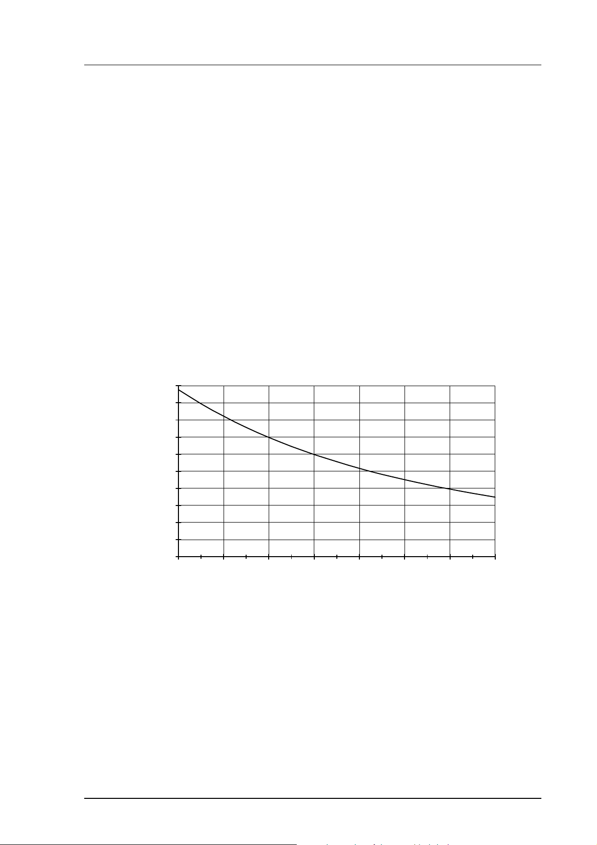
In the measurement of humidity and especially in calibration it is essential that
temperature equilibrium is reached. Even a small difference in temperature
between the measured object and the sensor causes an error. If the temperature
is +20 °C (+68 °F) and the relative humidity 50 %RH, a difference of ±1 °C
between the measured object and the sensor causes an error of ±3 %RH. When
the humidity is 90 %RH, the corresponding error is ±5.4 %RH.
The error is at its greatest when the sensor is colder or warmer than the surroundings and the humidity is high. A temperature difference of a few degrees
can cause water to condense on the sensor surface. In an unventilated space
evaporation may take hours; good ventilation accelerates evaporation. The
HUMICAP sensor starts to function normally as soon as the water has evaporated. If the condensed water is contaminated, the life span of the sensor may
shorten and calibration may change.
10
9
8
7
6
5
4
dRH (%RH)
3
2
1
0
-40 -20 0 20 40 60 80 100
Temperature (°C)
Figure 1 Measurement error at 100 %RH when the difference between
the ambient and sensor temperature is 1 °C
3

HMP230 SERIES
User's Guide M210225en-B
3. INSTALLATION
3.1. Selecting the place of installation
Choose a place which gives a true picture of the environment or process, and
is as clean as possible. Air should circulate freely around the sensor. A rapid
air flow is recommended; it ensures that the sensor head and the ambient air
are at the same temperature.
Install the transmitter in a place where no cold or hot spot can develop. When
the sensor head is installed in a duct or process channel where the temperature
is different from the ambient temperature, insulate the point of entry; this is
particularly important if the transmitter is installed with the sensor head
pointing downwards. Installing the sensor head of the HMP233, HMP234 and
HMP235 vertically is not recommended. An uninsulated installation could
lead to condensation in the sensor head and even when no condensation occurs, the resultant air flow may change the temperature near the sensor and
distort the readings.
Install the sensor head in the process wherever possible; avoid sample flows
where the gas temperature can drop below dewpoint temperature. Install the
sensor head transversely against the direction of the process flow.
In duct or channel installations drill a hole ready for a reference meter. Plug
the reference hole tightly.
Install the electronics housing away from possible steams escaping from the
process.
NOTE
To ensure an IP 65 class protection:
1. Always mount the transmitter housing with the cable
bushings pointing downwards.
2. Make sure that the connection cable has the right
thickness (∅ 7...10 mm) and that the cable bushing
is carefully tightened.
3. Pay always special attention to closing the
transmitter cover carefully and remember to tighten
all four screws.
4
HMP230 SERIES
M210225en-B User's Guide
3.2. Mounting
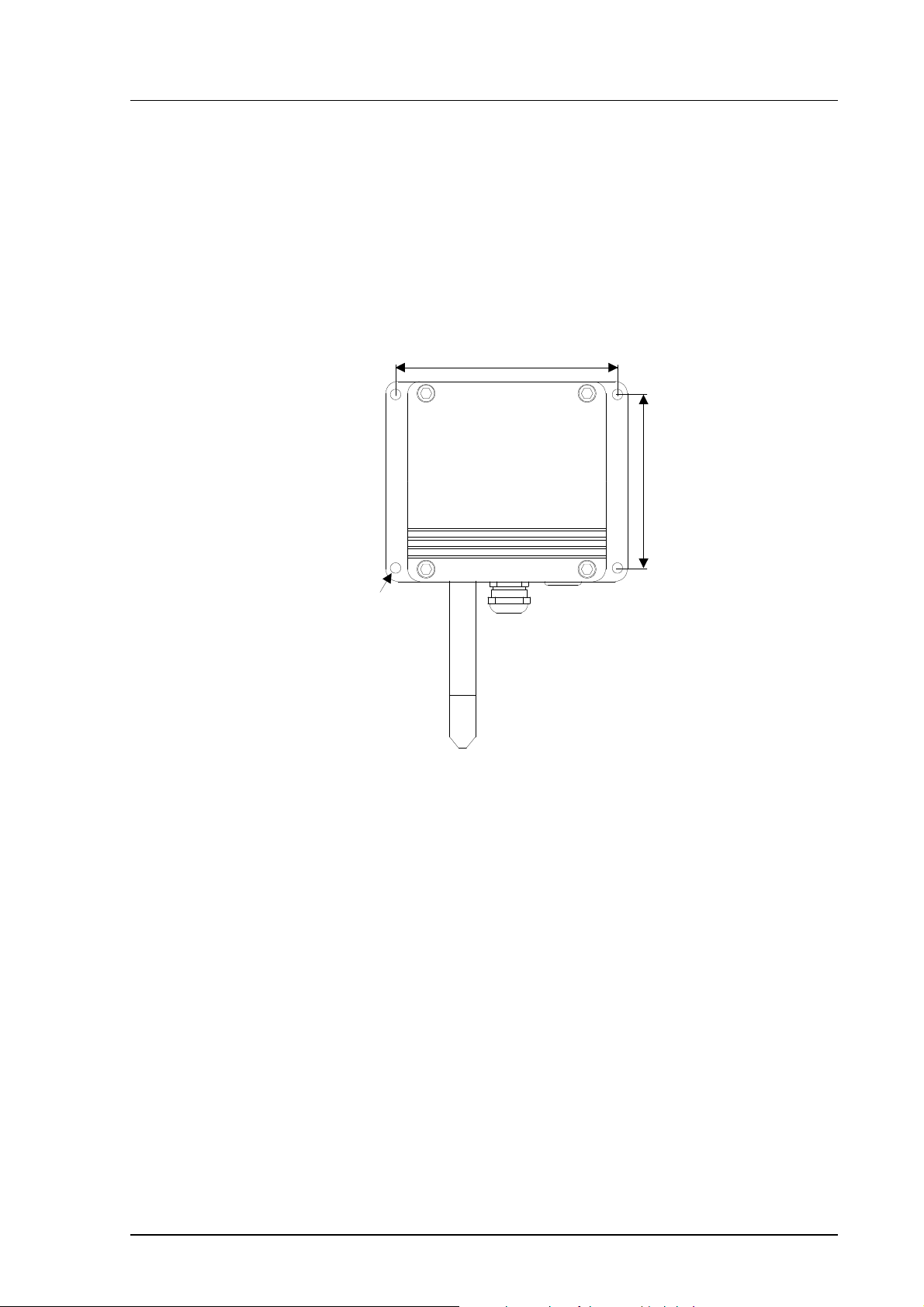
3.2.1. Mounting the HMP231
The best position for mounting the HMP231 is with the probe head pointing
downwards. Due to internal heat transfer, the transmitter should not be
mounted with the probe pointing upwards.
133
104
Ø 6.5
Figure 2 Mounting holes in the HMP230 transmitter housing.
3.2.2. Installing the HMP233, HMP234 and HMP235
It is recommended that the cable models HMP233, HMP234 and HMP235 be
mounted with the sensor head horizontally; this way, any water condensing on
the tube cannot flow onto the sensors. When there is no alternative but to
install the sensor head in the process vertically, the point of entry must be
carefully insulated. The cable must also be allowed to hang loosely as in
Figure 6; this prevents any condensed water from running onto the sensor head
along the cable.
If the process temperature is much higher than that of the environment, the
whole sensor head and preferably a piece of the cable must be inside the process.
When mounted on the side of a duct or channel, the sensor head must be inserted from the side (see Figure 8). If this is not possible and the sensor head
must be inserted from the top, the point of entry must be carefully insulated.
5
HMP230 SERIES
User's Guide M210225en-B
NOTE
During installation the sensor head must not be unsoldered from and again resoldered to the main printed
board of the transmitter. This procedure may damage
the humidity calibration of the transmitter.
3.2.3. HMP233 transmitter
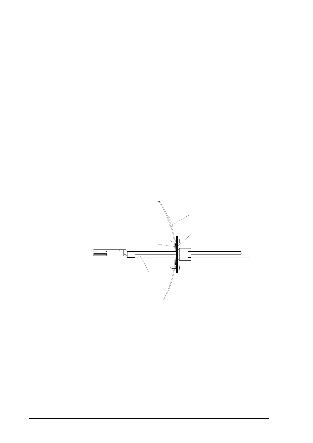
The HMP233 can be installed in ducts and channels with the help of the installation kit available; the kit consists of a flange, a supporting bar for the
sensor head cable and screws for attaching the flange to the wall of a duct.
With the help of the installation kit the distance between the sensor head and
the channel wall can be easily adjusted. The range of adjustment is 100...320
mm; the distance is measured from the tip of the sensor head to the flange.
duct wall
a plugged hole for reference
measurements
flange
sealing
supporting bar
Figure 3 Installing the sensor head of the HMP233 in a channel with
the help of flange and supporting bar.
6
HMP230 SERIES
M210225en-B User's Guide
The sensor head can also be installed vertically.
When a bushing is used, its
size is selected according to
the diameter of the sensor
head; the diameter of the
cable is increased by using
e.g. tape at the bushing
Figure 4 Vertical installation of the HMP233 sensor head
3.2.4. HMP234 transmitter
The atmospheric pressure has an effect on mixing ratio, wet bulb temperature
and enthalpy. Therefore, accurate calculations can be achieved only when the
ambient pressure is taken into consideration. The pressure is used for pressure
compensation of the HUMICAP sensor in order to ensure the best possible
measurement accuracy. If the process pressure differs from normal
ambient pressure, the value has to be entered in the transmitter memory
when using the transmitters HMP234 or HMP238. The pressure to be
entered is the absolute pressure in hPa or mbar (for pressure unit conversion,
see Appendix 10).
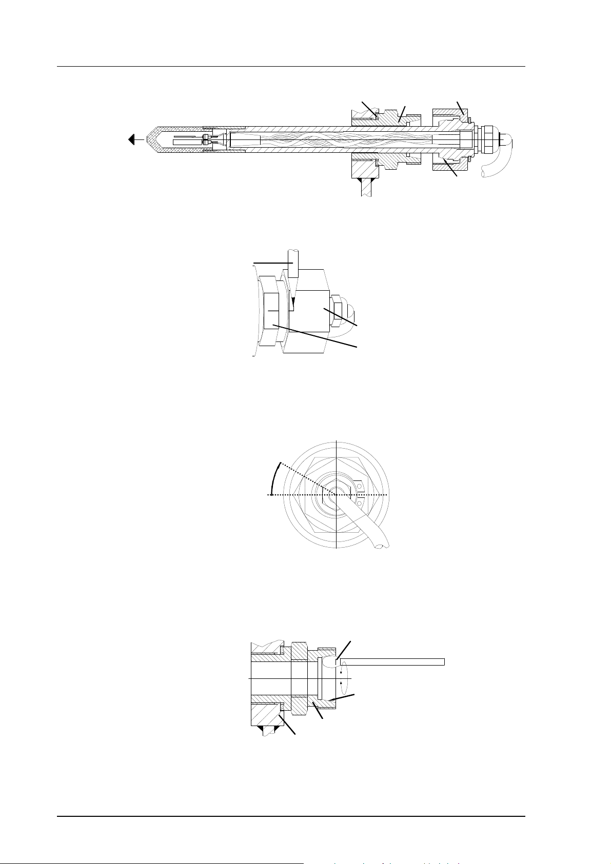
The HMP234 is supplied with a nut, a fitting body and a sealing washer. During handling the fitting body and the nut should remain in place on the body of
the sensor head to prevent damage to the highly polished surface.
To achieve a leak-tight assembly:
1. Remove the fitting body from the nut and the sensor head.
2. Fasten the fitting body to the chamber wall. Tighten the fitting body
into the threaded sleeve with a torque spanner. The tightening torque
is 150 ±10 Nm.
3. Insert the body of the sensor head into the fitting body and screw the
nut manually to the fitting body until the connection feels tight.
7
HMP230 SERIES
User's Guide M210225en-B
sealing washer
4. Mark both the fitting body and the nut hex.
A pen
nut
fitting body
fitting body
tightening cone
nut
5. Tighten the nut a further 30° (1/12 turn) or if you have a torque spanner tighten it with a torque of 80 ±10 Nm. NOTE: after detachment
the nut must be tightened without increased effort.
30°
6. The tightening cone of the fitting body has to be cleaned and greased
after every tenth detachment. Use high-vacuum grease (Down
Corning, Europe) or a similar grease.
clean cotton stick
tightening cone
fitting body
sealing
washer
The sealing washer has to be changed every time the fitting body is
detached.
8
HMP230 SERIES
M210225en-B User's Guide
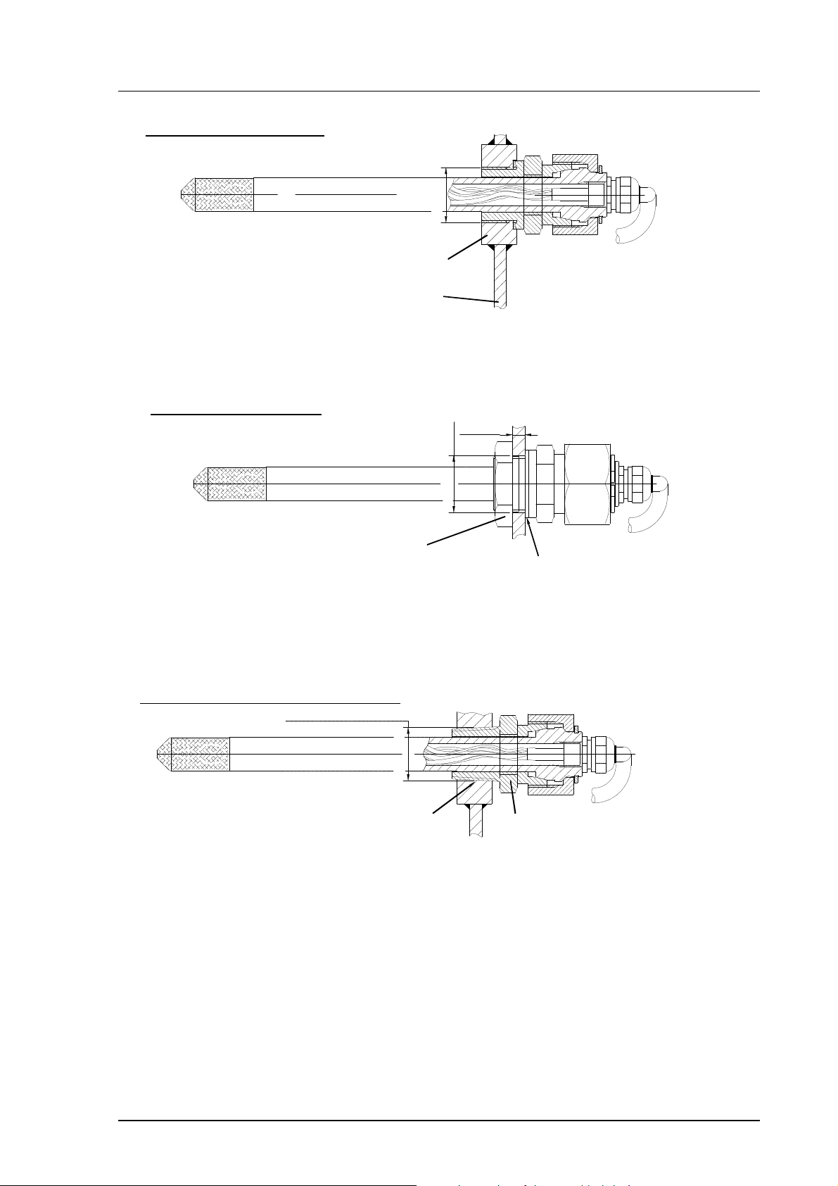
Fasten by threaded sleeve
Sealing by Metal sealing washer DIN 7603
M22x1.5
threaded sleeve M22x1.5/Ø40 x15
sheet metal
Fasten by Nut DIN 80705
Check the thickness of the sheet metal
according to the pressure of the chamber
s=3...6mm
(boring)
nut DIN 80705-M22x1.5 (AISI 316)
tightening torque=150 Nm ±10 Nm
NPT Conical pipe threaded connection
ANSI/ASME B1.20.1-1983
sealing by anaerobic pipe thread seal
(SWAK, Cajon Company) or PTFE
(teflon) tape
Ø22+0.3
sealing by Metal sealing washer
DIN 7603
1/2 -14 NPT
fitting body. VAISALA code 17225
(AISI 316Ti). Body hex = 27 mm
tightening torque=150 Nm ±10 Nm
Figure 5 Some examples on the installation of the HMP234 sensor head
9
HMP230 SERIES
User's Guide M210225en-B
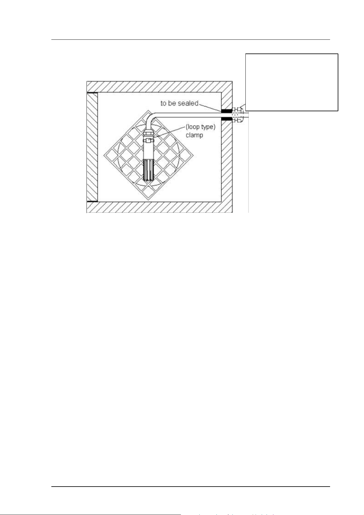
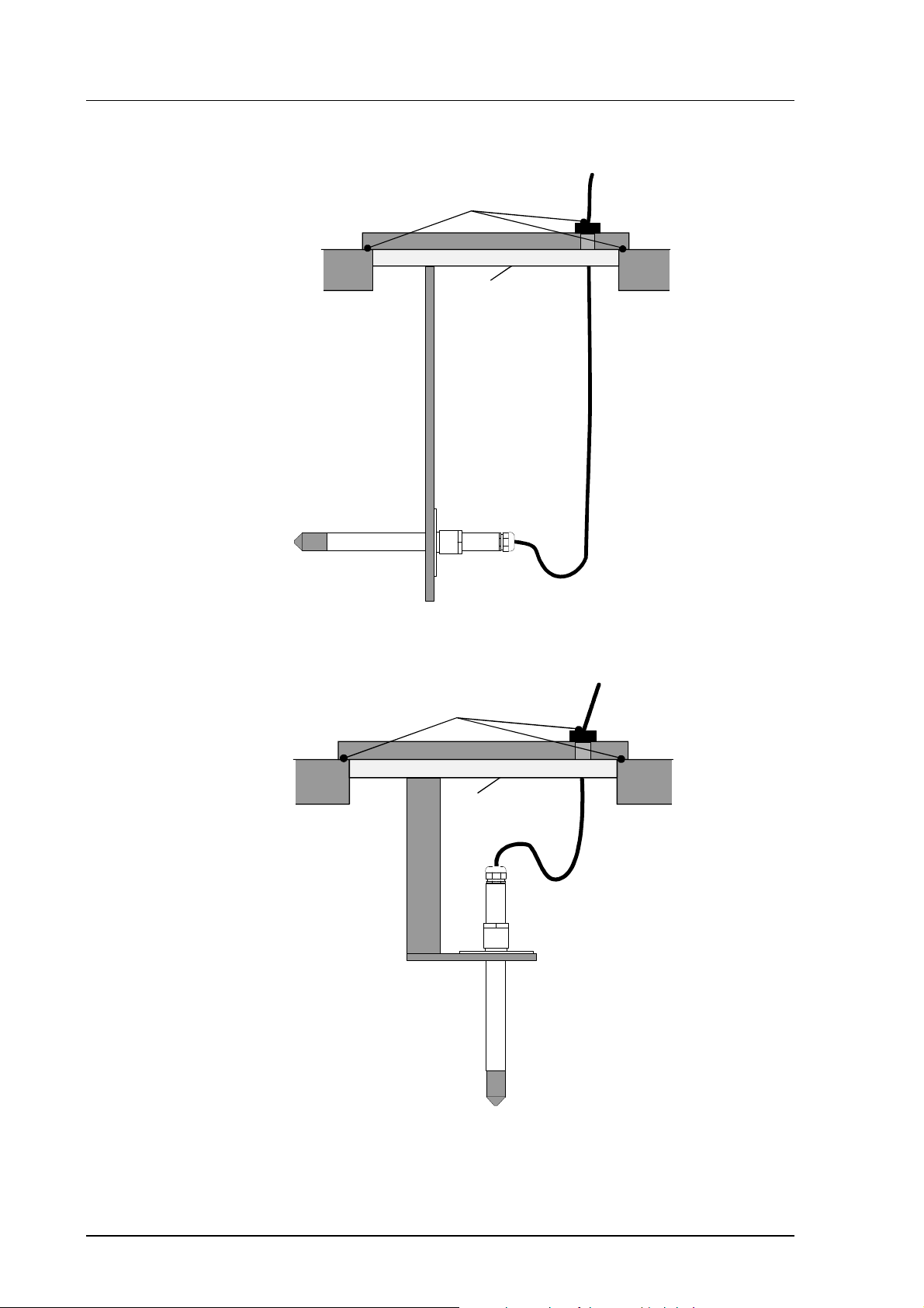
3.2.5. HMP235 transmitter
to be sealed
to be insulated
Figure 6 Installing a transmitter in a process with the sensor head
horizontally
to be sealed
to be insulated
10
Figure 7 Installing a transmitter in a process with the sensor head
downwards (not recommended)
HMP230 SERIES
M210225en-B User's Guide
Figure 8 Mounting the sensor head on a duct or channel.
When the sensor head is installed in a duct or channel, the temperature difference between the air in the duct and outside it must be small as the sensor
head conducts heat.
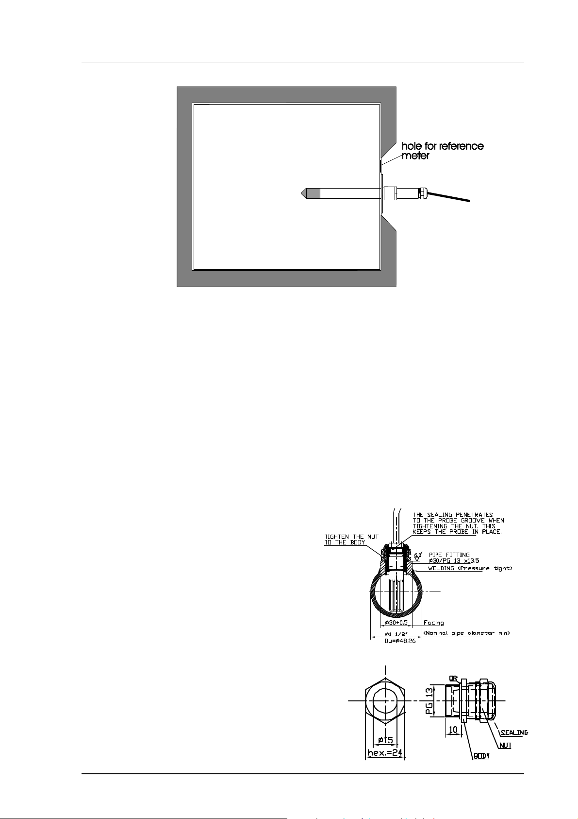
3.2.6. HMP237 transmitter
HMP237 has a small size probe made of stainless steel. The sensor head
withstands temperatures -40...180 ºC (-40...356 ºF) and pressure up to 10 bar
(1MPa, 145 psi). The probe is suitable for applications where a mechanically
very durable leak proof probe is needed. The sensor head of the HMP237 can
be installed in a channel with the help of flange and supporting bar (see Figure
3). Duct and cable installations are shown in Figures 9 and 10.
Figure 9. HMP237 Duct
installation.
1. Make hole with PG13 thread
in the measurement chamber or
process wall. The smoothness of
the thread circle should be
R= 6.3 microm.
2. Install the cable gland (AGRO
nr 1113.60.15) on the thread of
the process wall.
3. Push the probe through the
gland so deep that the backside of
the probe is flust with the cable
gland nut.
4. Tighten the cable gland nut,
the probe will lift up slightly.
Cable gland (AGRO 1113.60.15)
11

HMP230 SERIES
User's Guide M210225en-B
1. Make a hole as described in duct installation,
Temperature < 180ºC
Pressure < 10 bar
Figure 10. HMP237 cable installation.
Figure 9.
2. Take out the rubber sealing from the AGRO
Nr 1013.30.91. Drill a 6 mm hole in the middle
of the rubber sealing. Cut the jacket of the
sealing.
3. Thread the probe through the AGRO-fitting
body and nut (without the cut rubber).
4. Set the cut rubber sealing through the cable
between the fitting body and the nut.
5. Turn the fitting body to the hole, push the
rubber sealing into the fitting body and tighten
the nut.
3.2.7. HMP238 transmitter
The atmospheric pressure has an effect on mixing ratio, wet bulb temperature
and enthalpy. Therefore, accurate calculations can be achieved only when the
ambient pressure is taken into consideration. The pressure is used for pressure
compensation of the HUMICAP sensor in order to ensure the best possible
measurement accuracy. If the process pressure differs from normal
ambient pressure, the value has to be entered in the transmitter memory
when using the transmitters HMP234 or HMP238. The pressure to be
entered is the absolute pressure in hPa or mbar (for pressure unit conversion,
see Appendix 10).
It is recommended that the sensor head is installed directly in the process
through the ball valve assembly. When the ball valve set is used, the chamber
or the duct does not have to be emptied or shut down for installation or
removal of the probe. Install the sensor head transversely against the direction
of the process flow.
However, if direct installation is not possible for some reason, the probe can
be installed in a "leak-through" position provided that there is a slight
overpressure in the process. In this installation, the probe is mounted behind
the ball valve assembly. The flow passes through the sensor head and leaks
out through a vent hole in the fitting body. However, make sure that the
temperature at the measurement point is equal to that of the process.
12
HMP230 SERIES
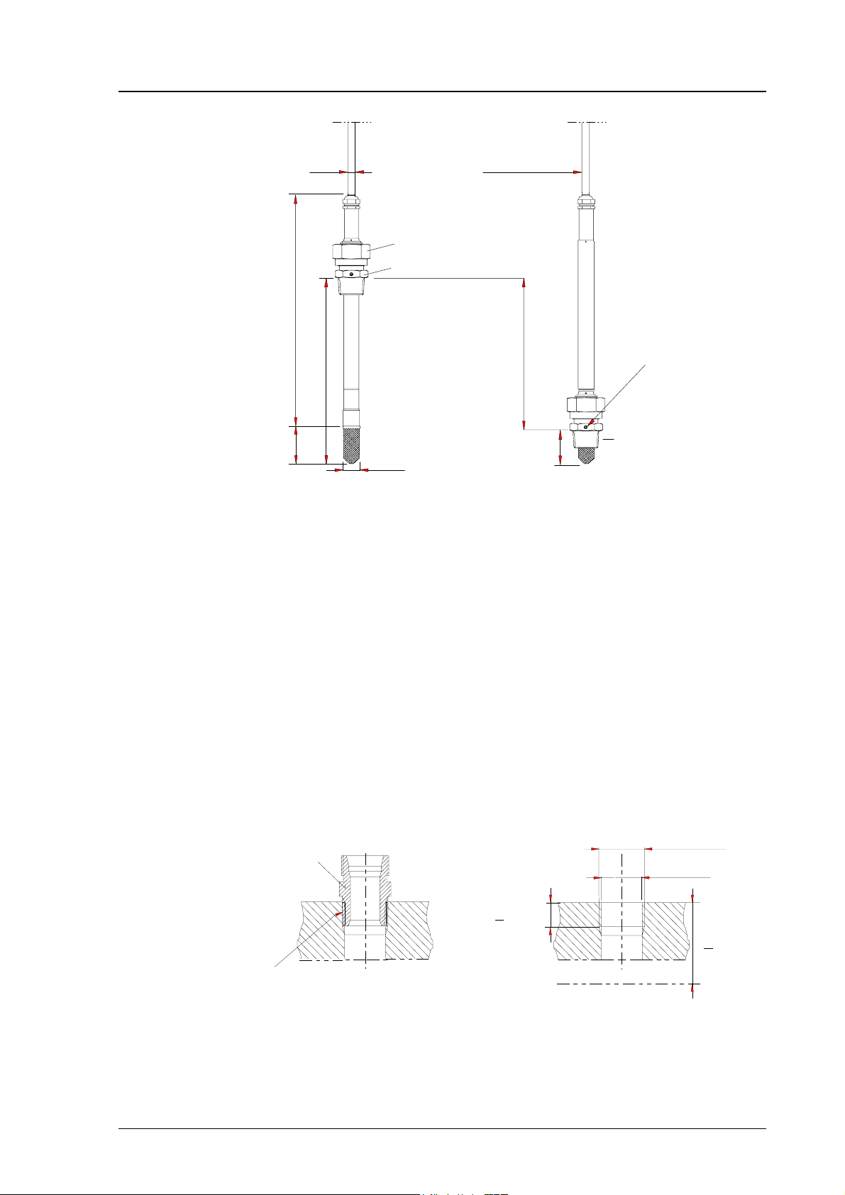
PROBE UP
PROBE
PUSHED
DOWN
cable length
2, 5 or 10 m
ø5.5
178
31
ø13.5
adjustment
range120 mm
29
R1/2 ISO 7/1
non leaking screw (A)
(factory setting)
or leak screw (B)
(included in the package)
149
clasp nut
fitting body
M210225en-B User's Guide
Figure 11 HMP238 Probe dimensions (in mm)
NOTE
Take care not to damage the pipe of the probe. If the
pipe is damaged, the probe head is less tight and it will
not go through the clasp nut.
3.2.7.1. Mounting; overview
fitting body
hex = 24mm
tapered thread
R1/2 ISO 7/1
Examples of
sealings:
sealing with:
1. LOCTITE® No 542 + activ. No 7649 (t=-55...+150 °C)
2. MEGA-PIPE EXTRA No 7188 (t=-55.. .+170 °C)
3. PTFE tape (t=-60...+210 °C) NOTE: the tape does not lock
the parts together. Therefore, use two fork spanners (hex 24 and
27 mm) for tightening and opening the clasp nut of the probe
(provided with
the probe)
Thread for the
fitting body:
>10.5mm
Process or pipe wall
parallel thread
G1/2 ISO 228/1
(BS 2779, JIS B0202)
ø19mm dr illing
>40mm
Figure 12 Sealing and thread cutting for the fitting body
13
HMP230 SERIES
User's Guide M210225en-B
The fitting body can be installed e.g. on standard pipe fittings (G 1/2 ISO
228/1) or on a thread in the process wall. If the wall thickness is more than
10.5 mm, it is recommended to use a welded sleeve (see Figure 14). Note that
the minimum recommended distance of the fitting body and probe head is 40
mm (see Figure 12).
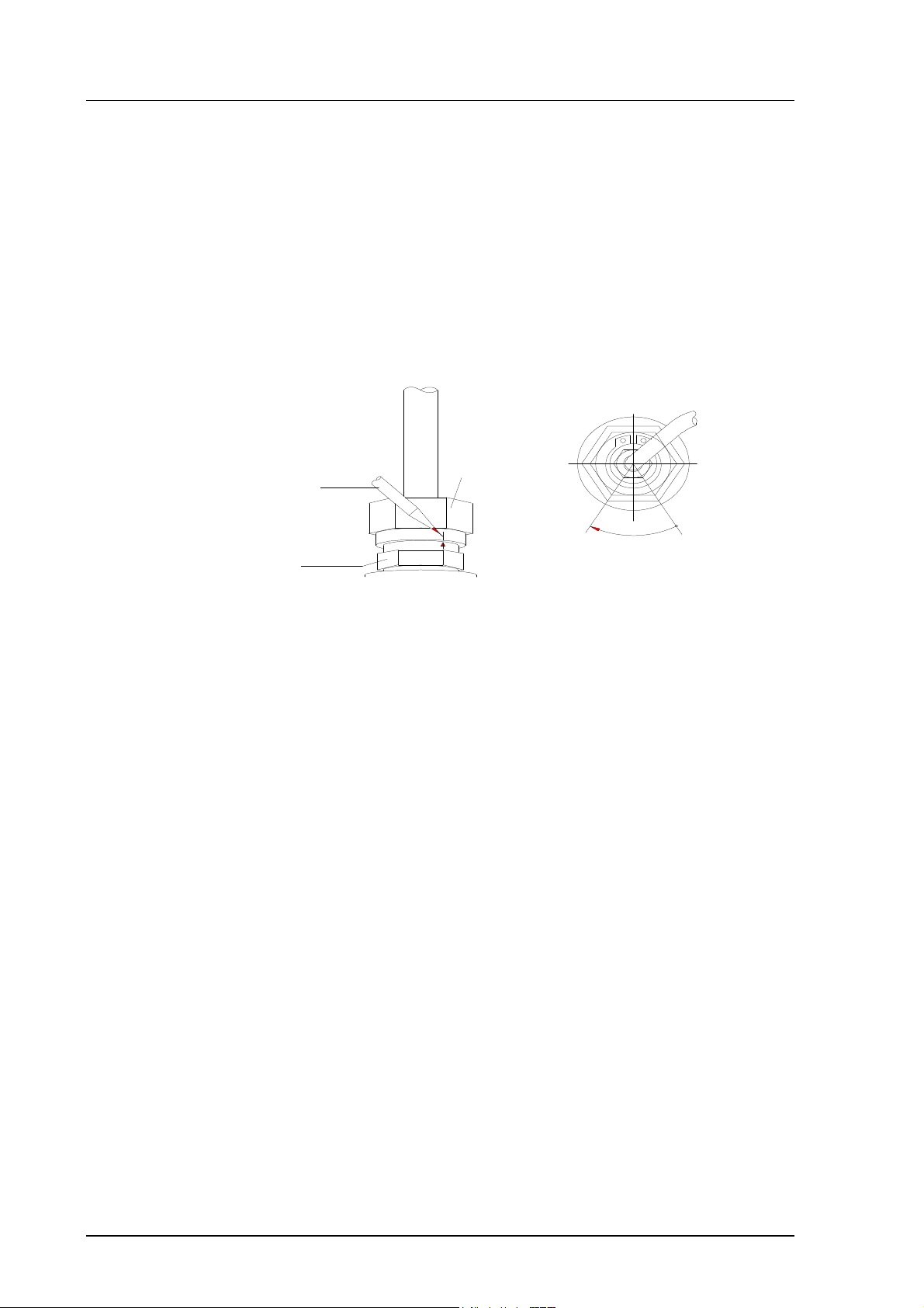
Adjust the probe to a suitable distance according to the type of installation and
tighten the clasp nut first manually; mark the fitting body and the clasp nut
and tighten the nut a further 50...60° with a fork spanner (see Figure 13).
probe
a pen
clasp nut
60°
fitting body
max.
Figure 13 Tightening the clasp nut.
NOTE
Be careful not to tighten the clasp nut more than 60° as
this may result in difficulties when trying to open it.
When the probe is installed directly on the process wall or pipe, note that a
closing valve may be needed on both sides of the installed probe so that the
sensor head can be removed from the process for calibration and maintenance.
If the sensor head is installed in a pressurized chamber, always make sure that
the pressure of the chamber is equalized with the ambient pressure prior to
removing the probe.
14
HMP230 SERIES
M210225en-B User's Guide
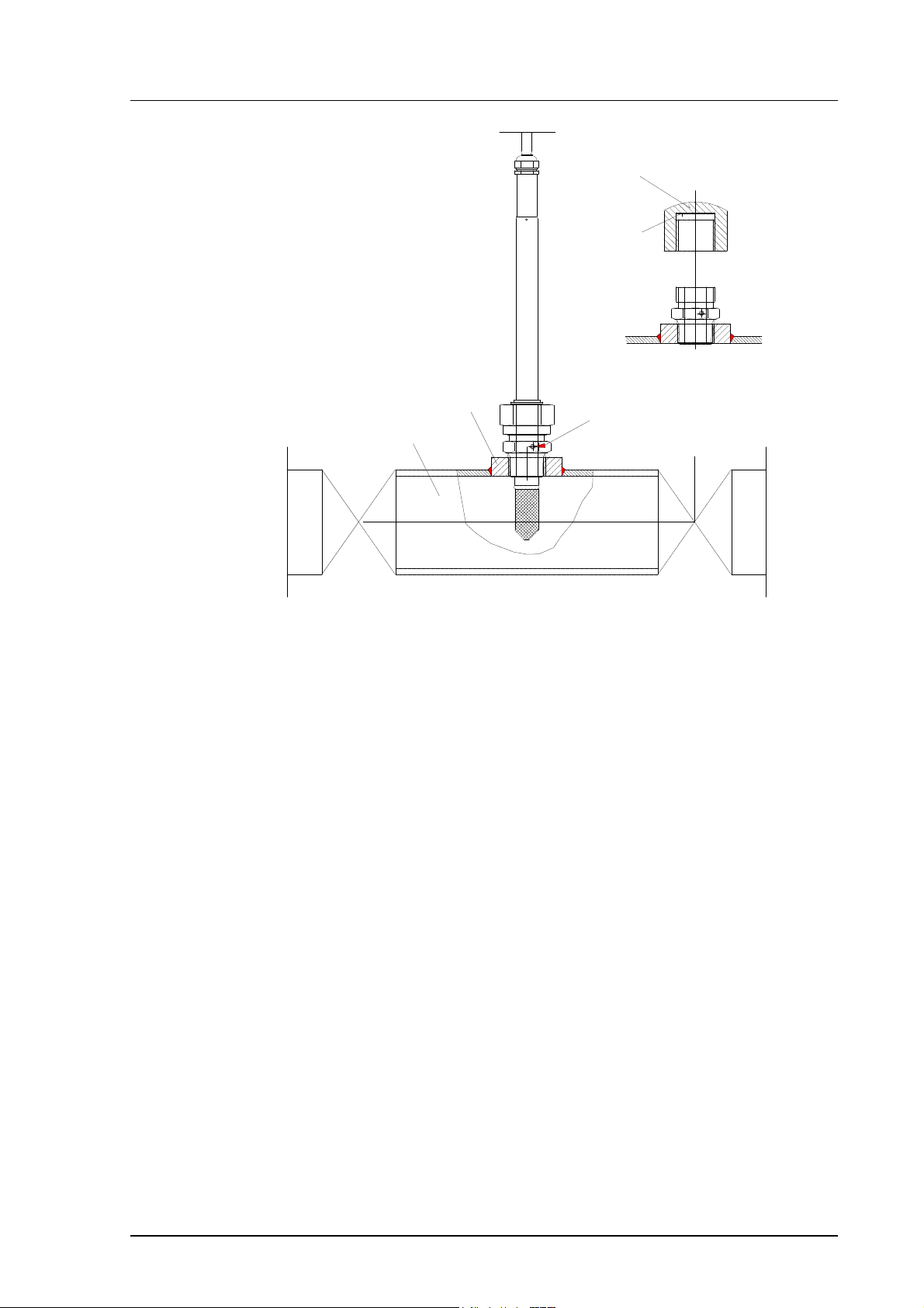
capped nut
DIN 917-M22x1.5
when the probe is pulled
out for maintenance, cap
the hole with a capped nut;
this way, the process can be
open although the probe is
not in place
sealing
welded sleeve
(G1/2)
process pipe
Non leaking screw
(screw A)
closing valve
(ball valve)
Figure 14 Installing the sensor head directly on the process wall
15
HMP230 SERIES
User's Guide M210225en-B
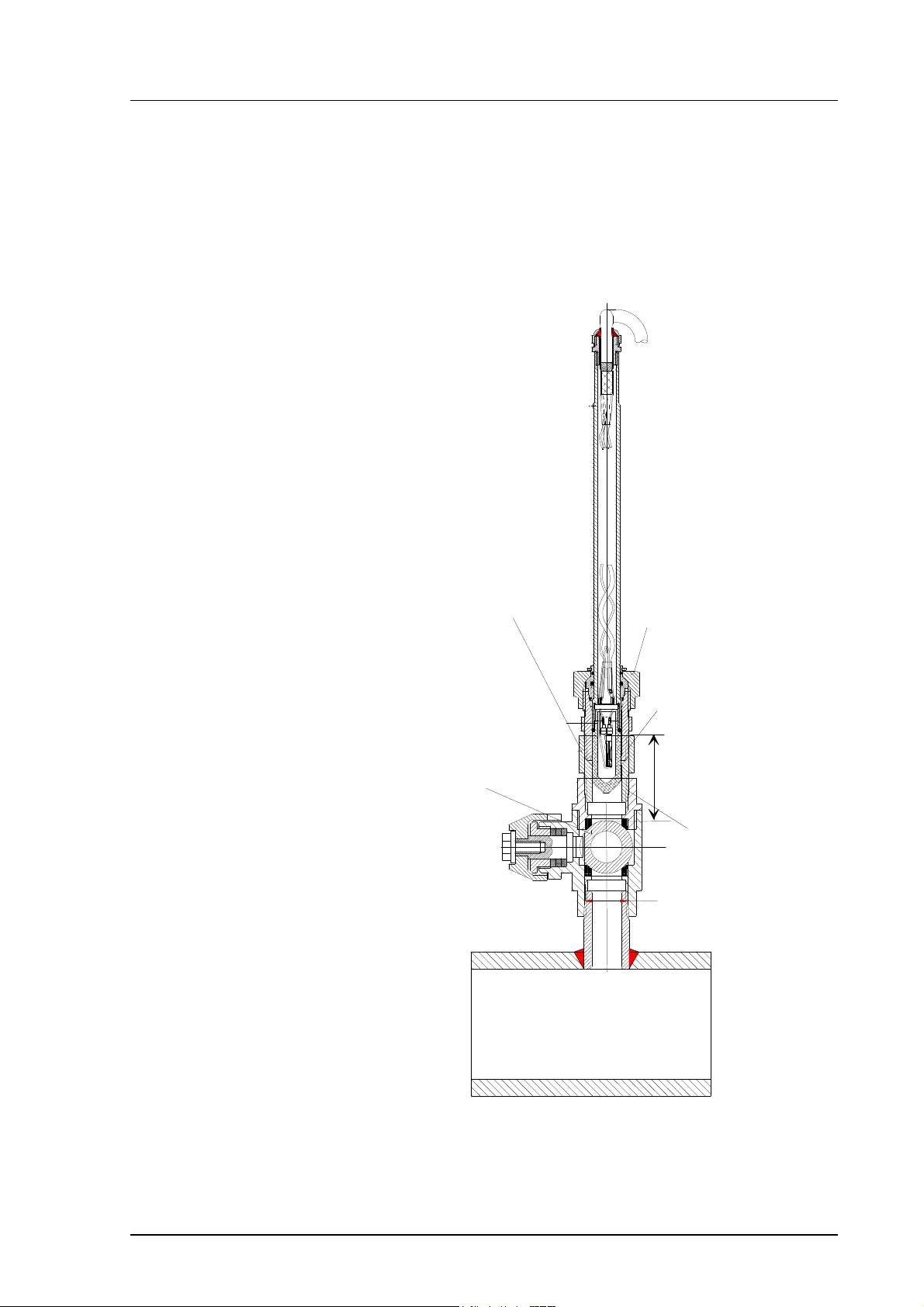
3.2.7.2. Installing the probe through the ball valve assembly
The best way to install the sensor head is through the ball valve assembly. Use
a 1/2” ball valve assembly with a ball hole of ∅14 mm or more. In this kind of
installation, it is not necessary to empty or shut down the process for installing
or removing the sensor head. If the sensor head is installed in a process pipe,
please note that the nominal size of the pipe must be at least 1 inch. See pages
16 - 19 for detailed instructions.
16
Figure 15 Installing the sensor head through the DMP248BVS ball valve
assembly
NOTE
The probe can be installed in the process through the
ball valve assembly provided that the process pressure
is less than 10 bars. This way, the process does not have
to be shut down when installing or removing the probe.
However, if the process is shut down before removing
the probe, the process pressure can be max. 40 bars.
HMP230 SERIES
d
M210225en-B User's Guide
See Figure 16 through Figure 18 for detailed description of installation
through the ball valve assembly. This installation is possible provided that
the process pressure is less than 10 bars. Note also that if the sensor head is
installed in a process pipe, the nominal size of the pipe must be at least 1 inch.
• STEP I: mount the probe with the ball valve assembly closed; tighten the
clasp nut manually
bushing R1/2 cone/G1/2(40 bar)
e.g. Camozzi 2520-1/2-1/2
(the bushing serves for
moving the probe (sinter)
to such a distance from the
ball valve that the valve
can be closed)
ball valve 1/2" (40 bar)
e.g. Atlas Copco:BAL-1A 15 (G1/2)
clasp nut
fittin g body
R1/2 cone, seale
>30 mm
bushing
R1/2 cone
sealed
nipple
R1/2 cone
sealed
Figure 16 Installing the probe through the ball valve assembly; step 1.
17
HMP230 SERIES
User's Guide M210225en-B
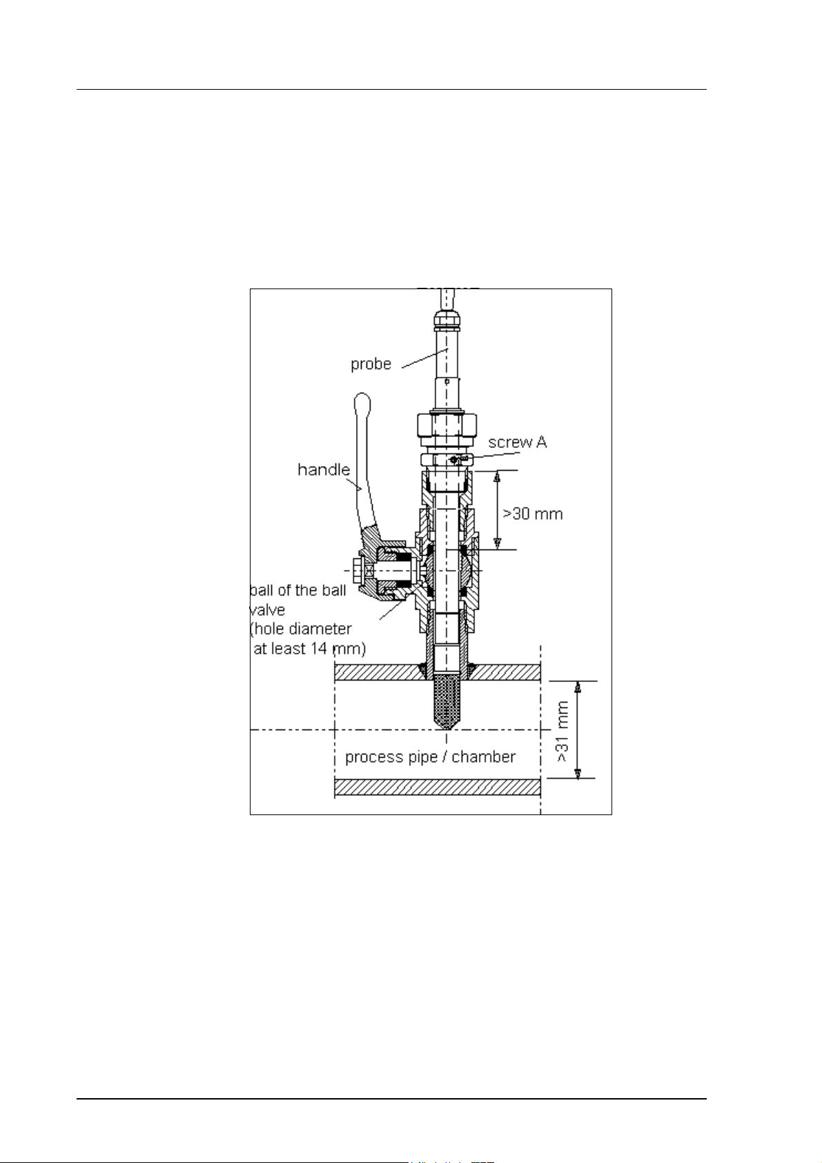
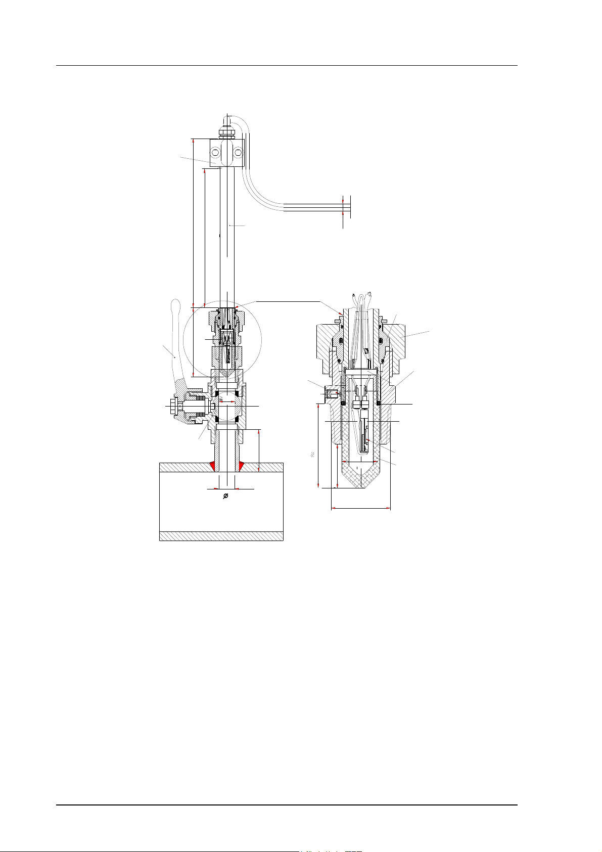
• STEP 2: open the ball valve assembly
manual
press
tool
120mm
probe pipe
148 mm
adjustment range
marking groove
handle
61
ø5.5
fitting
ferrule
c lasp nut
(hex 27 mm)
fitting body
(hex. 24 mm)
O-ring
DRYCAP® sensor
filter
ball of the
ball valve
ø14
> 14
=
leak screw (B)
(hex. 1.5 mm)
(40)
29
15
R1/2 ISO 7/1
ø13.5
Figure 17 Installing the probe through the ball valve assembly; step 2
(measures in mm)
18
HMP230 SERIES
M210225en-B User's Guide
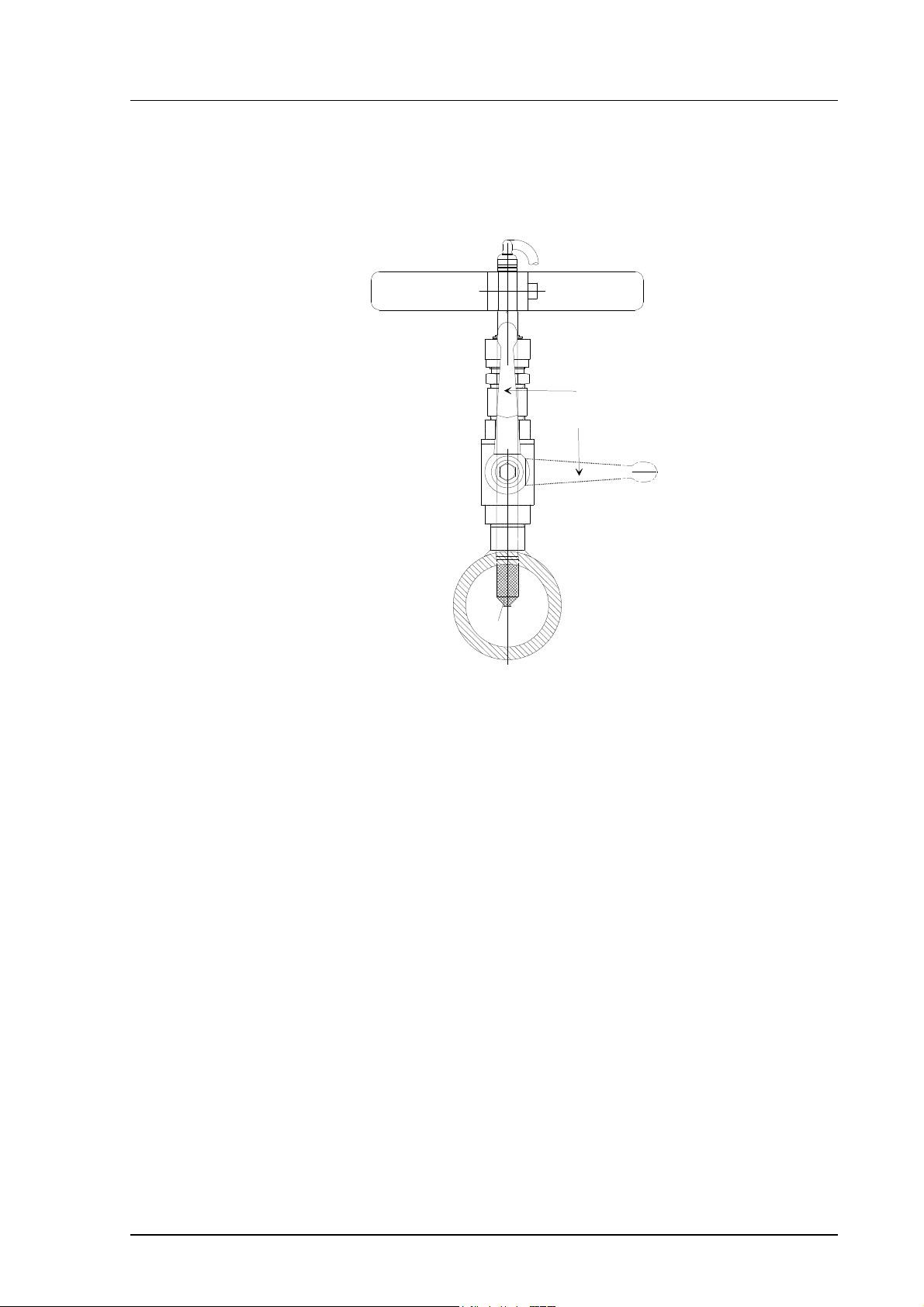
• STEP 3: push the probe head through the ball valve assembly into the
process. If the pressure is high, use a manual press tool. Note that the
sensor head must be pushed so deep that the filter is completely inside the
process flow.
MANUAL
PRESS TOOL
VALVE OPEN
VALVE CLOSED
FILTER
Figure 18 Installing the probe through the ball valve
assembly: step 3
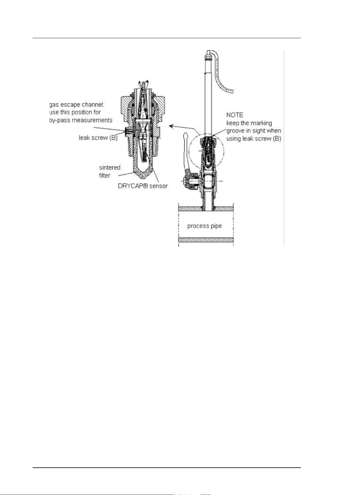
For by-pass measurements, the probe is mounted behind the ball valve
assembly and non-leaking screw A on the fitting body is replaced with leaking
screw B and O-ring is placed on the groove of the sintered filter. Screw B has
a small (0.08 mm) laser-made hole in the middle; the gas or air to be measured
passes through the sintered filter and by the sensor, and leaks out through the
screw. The process pressure reduces in the hole of the screw B. This
installation is recommended if the process flow rate is >20 m/s and there is an
over-pressure in the process.
19
HMP230 SERIES
User's Guide M210225en-B
Figure 19 Installing the sensor head for by-pass measurements.
When pushing the probe head through the ball valve assembly, be careful not
to break the sintered filter. Open and close the ball valve assembly with the
marking groove always in sight. In by-pass measurements, the clasp nut is
tightened manually prior to pressing the probe through the valve. When the
probe has been pressed through and the valve is open, the nut is tightened
50...60° with a fork spanner (hexagon 27 mm).
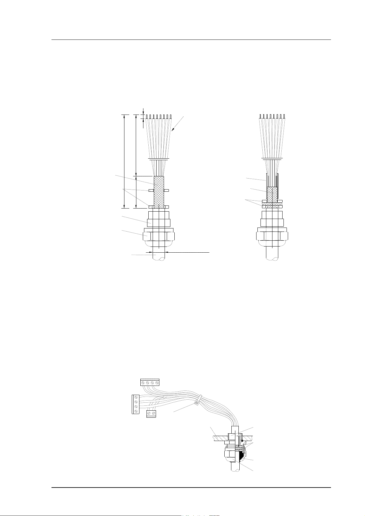
3.3. Grounding
A single electrical cable with a screen and three to ten wires is recommended
for power and analogue output/serial bus connections. The cable diameter
should be 7...10 mm.
The screen of the electrical cable must be grounded properly to achieve best
possible EMC performance. Recommended cable shield is done in the cable
gland as shown below.
• remove the brass disks, rubber ring and nut from the transmitter
housing
20
• strip 165 mm of the cable insulation, but leave 25 mm of the braid
visible
• slip the nut and rubber ring over the cable insulation
HMP230 SERIES
brass disks
rubber ring
M210225en-B User's Guide
• slip the brass disk that has the bigger hole in it over the braid so that
it rests against the cable insulation
• slip the other brass disk over the wires to the middle of the braid
flexible wires 0.5 mm²
(AWG 20), stranded wires
recommended
3
140
165
braid
brass
disks
rubber
ring
nut
cable
• push back the braid and press it between the two brass disks to
25
D = Ø 7...10 mm
(If the cable diameter is less
than 7mm, use a shrinking
tube or an adhesive tape)
shielding tube
braid
brass disks
achieve a full 360° grounding; the fold between the disks should have
the same diameter as the brass disks
• secure the braid with a shielding tube
• insert the wires into the transmitter housing through the gland.
• tighten the nut
• connect the wires into the screw terminals and fasten a cable tie
around the wires
cable tie
transmitter housing
gland
nut
21
HMP230 SERIES
+
POWER SUPPLY
User's Guide M210225en-B
NOTE
When the cable is grounded as above, the metallic parts
of the sensor head, the shield of its cable, the transmitter housing and the shield of the signal cable to external
system are all connected to each other. After this the
whole system can be grounded from one point only. If
the grounding is made via several points (sensor head,
transmitter housing, signal cable), make sure that the
different groundings are made to the same grounding
potential. Otherwise harmful grounding currents may be
generated. If you do the grounding via the transmitter
housing, use one serrated lock washer between a mounting screw and the housing; the lock washer breaks the
paint on the housing.
When mains power supply is in use, the housing must be grounded by protective ground wire using a grounding screw at the right-hand side of the power
supply module (see Appendix 2).
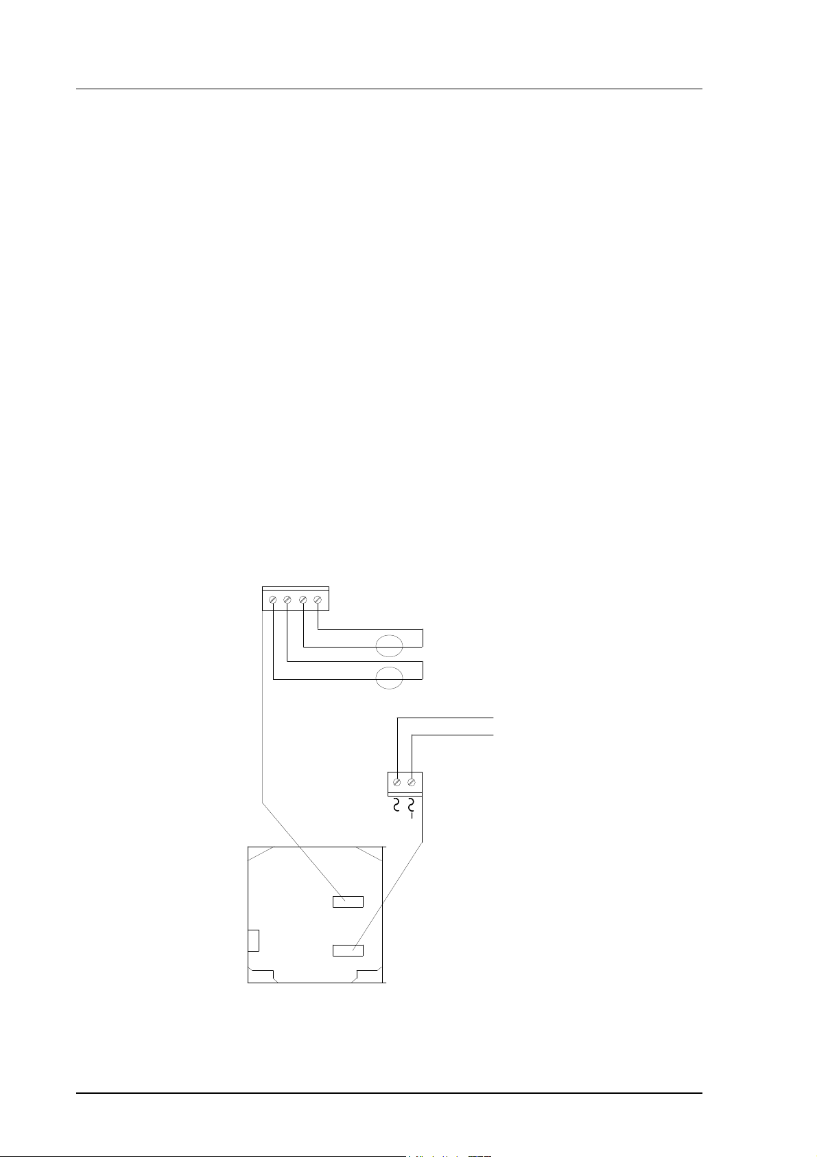
3.4. Electrical connections
CH2
CH1+
CH1-
X2
CH1- and CH2- are connected
CH2-
together internally
+
V
mA
+
V
mA
CURRENT/VOLTAGE
-
OUTPUTS
-
(INTERNAL OR
EXTERNAL)
Do not use power supply
ground (-) as output signal
ground
24 V +
22
X1
OPENED COVER OF THE HMP230
Figure 20 Electrical connections
HMP230 SERIES
M210225en-B User's Guide
Power supply 24 VDC
24 VAC (see page 23)
with power supply module 115/230 VAC
Output signals 0...20 mA, 4...20 mA
0...1 V, 0...5 V, 0...10 V
Power supply ground (-) is connected to the housing with parallel connection
of 15 nF capacitor and 300 kΩ resistor.
See Appendix 2 on how to connect the power supply module to the
transmitter.
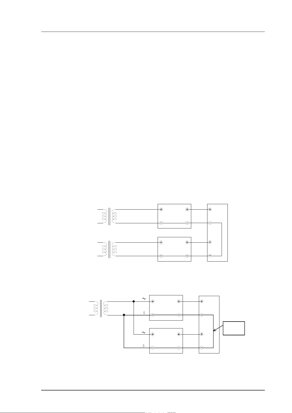
3.4.1. Connection to a 24 VAC supply
The HMP230 transmitters can also be connected to a 24 VAC supply without
an external rectifier. However, when more than one transmitter is connected to
one 24 VAC transformer, a common loop is formed and there is an increased
risk of a short-circuit. To avoid this, always use separate floating supply for
each transmitter (see Figure 21 A). However, if several transmitters have to
share one transformer, the phase (∼) must always be connected to + connector
in each transmitter (see Figure 21 B).
A) NO COMMON LOOP FORMED - RECOMMENDED
HMP230 transmitter
24 VAC
24 VAC
HMP230 transmitter
B) COMMON LOOP FORMED -
HMP230 transmitter
24 VAC
supply
voltage
signal
supply
supply
voltage
output
voltage
signal
output
NOT RECOMMENDED!
signal
output
Controller
Controller
shared
common
line
supply
voltage
signal
output
HMP230 transmitter
Figure 21 Connecting the transmitters to a 24 VAC supply
23

HMP230 SERIES
User's Guide M210225en-B
4. COMMISSIONING
When HMP230 transmitters leave the factory, their measurement ranges and
output signals have already been scaled according to the order form completed
by the customer. Units are calibrated at the factory and ready to operate when
the power is turned on. If you take into use active current, voltage or serial bus
outputs, make these connections first; Appendix 9 describes them in detail.
NOTE
Make sure that the power is not turned on until cables
have been connected to screw terminals!
In transmitters with display, the software version appears for a few seconds
when the power is turned on. After this, measurement results appear
automatically. Should an error message appear on the display, consult
Appendix 5.
If your transmitter has a blank cover and the LED indicator inside the housing
lights up, consult Appendix 5 for further information.
Appendix 7 contains information on how to determine the ranges for alarm
outputs and alarm controls when an alarm output unit is used.
4.1. Changing the parameters
If necessary, the user can subsequently change the measurement units between
metric and non-metric and select and scale the output signals with software
functions. This is done through commands, either utilizing the menus on the
local display or giving commands through the serial interface (see
Appendices). Most often the commands are used to change the settings of the
two analogue channels.
4.2. Security lock jumper
Before the settings can be changed, the user must first remove the security
lock jumper in connector X15 (see Figure 22). The security lock jumper makes
it impossible to change the transmitter settings by mistake.
24
Loading...