


 Loading...
USER'S GUIDE
Vaisala WINDCAP© Ultrasonic
Wind Sensor Series
WMT700
M211095EN-E
Vaisala Oyj |
Phone (int.): |
+358 |
9 8949 1 |
P.O. Box 26 |
Fax: |
+358 |
9 8949 2227 |
FI-00421 Helsinki |
|
|
|
Finland |
|
|
|
Visit our Internet pages at www.vaisala.com.
© Vaisala 2013
No part of this manual may be reproduced, published or publicly displayed in any form or by any means, electronic or mechanical (including photocopying), nor may its contents be modified, translated, adapted, sold or disclosed to a third party without prior written permission of the copyright holder. Translated manuals and translated portions of multilingual documents are based on the original English versions. In ambiguous cases, the English versions are applicable, not the translations.
The contents of this manual are subject to change without prior notice.
This manual does not create any legally binding obligations for Vaisala towards customers or end users. All legally binding obligations and agreements are included exclusively in the applicable supply contract or the General Conditions of Sale and General Conditions of Service of Vaisala.
_________________________________________________________________________________
Table of Contents |
|
CHAPTER 1 |
|
GENERAL INFORMATION.......................................................................... |
11 |
About This Manual ................................................................. |
11 |
Contents of This Manual ..................................................... |
11 |
Version Information ............................................................. |
12 |
Related Manuals ................................................................. |
12 |
Documentation Conventions ............................................... |
13 |
Safety....................................................................................... |
13 |
Recycling ................................................................................ |
14 |
Regulatory Compliances ....................................................... |
15 |
Trademarks ............................................................................. |
16 |
Warranty.................................................................................. |
16 |
CHAPTER 2 |
|
PRODUCT OVERVIEW................................................................................ |
17 |
Introduction to WMT700 ........................................................ |
17 |
Ordering Options................................................................. |
23 |
Measurement Range...................................................... |
23 |
Temperature Range....................................................... |
23 |
Heating........................................................................... |
24 |
Digital Communication Interface.................................... |
24 |
Digital Communication Profile........................................ |
25 |
Digital Communication Units.......................................... |
25 |
Analog Output Signal for Wind Speed Channel............. |
26 |
Analog Output Signal for Wind Direction Channel......... |
27 |
Connection Cables......................................................... |
27 |
Mounting Adapters ......................................................... |
28 |
Accessories.................................................................... |
28 |
Manual ........................................................................... |
29 |
Example of WMT703 Configuration ............................... |
29 |
Accessories ......................................................................... |
30 |
Bird Cage ....................................................................... |
31 |
WM Verifier .................................................................... |
32 |
Cables ............................................................................ |
33 |
Cable Tightening Tool.................................................... |
34 |
CHAPTER 3 |
|
FUNCTIONAL DESCRIPTION..................................................................... |
35 |
Operating Principle ................................................................ |
35 |
Coordinate Systems: Vector and Polar Calculations ......... |
38 |
Wind Speed and Direction Averaging .................................. |
40 |
Scalar Averaging................................................................. |
40 |
Wind Direction Coasting ................................................ |
41 |
Vector Averaging................................................................. |
41 |
Measurement Methods .......................................................... |
42 |
Continuous Measurement ................................................... |
42 |
VAISALA_________________________________________________________________________ 1
User's Guide ______________________________________________________________________
Wind Measurement on Request .......................................... |
42 |
Host System Connections and Interfaces............................ |
43 |
Serial Communication and Analog Output .......................... |
45 |
Serial Communication............................................................ |
45 |
Digital Communication Interface.......................................... |
45 |
Profiles................................................................................. |
46 |
Protocols.............................................................................. |
47 |
Measurement and Configuration Modes ............................. |
47 |
Serial Interface Timing......................................................... |
49 |
Analog Output......................................................................... |
50 |
Analog Output Types........................................................... |
50 |
Analog Output Scaling......................................................... |
52 |
Limitations for Output Signals.............................................. |
54 |
Missing Readings and Error Indication................................ |
55 |
CHAPTER 4 |
|
INSTALLATION ............................................................................................ |
57 |
Maritime Installations ............................................................. |
57 |
Selecting Installation Location.............................................. |
58 |
Installation Procedure ............................................................ |
62 |
Unpacking............................................................................ |
62 |
Mounting .............................................................................. |
63 |
Mounting on Vertical Pole Mast...................................... |
64 |
Mounting on Horizontal Cross Arm ................................ |
68 |
Checklist for Connection Cables ......................................... |
73 |
Alignment............................................................................. |
74 |
Alignment Tuning............................................................ |
75 |
Installing Bird Cage ............................................................. |
75 |
Wiring....................................................................................... |
77 |
Cables.................................................................................. |
77 |
Cable 2 m, Cable 10 m, Cable 15 m, and Cable |
|
26 m..................................................................................... |
78 |
RS485 for COM2 with Cable 2 m and 10 m................... |
79 |
RS485 Cable 2 m and RS485 Cable 10 m.......................... |
80 |
Connector Signals ............................................................... |
81 |
Heating..................................................................................... |
82 |
Heated Transducers ............................................................ |
82 |
Heated Transducers and Arms............................................ |
83 |
Heated Body, Transducers, and Arms ................................ |
83 |
Powering.................................................................................. |
84 |
Operating Power.................................................................. |
84 |
Heating Power ..................................................................... |
87 |
Power and Cable Recommendations for Fully |
|
Heated WMT700 ............................................................ |
87 |
Upgrading from WS425 to WMT700...................................... |
89 |
Mounting with WS425 Mounting Kit..................................... |
90 |
Before You Start .................................................................. |
94 |
Mounting Procedure ............................................................ |
96 |
Tightening Connector ..................................................... |
97 |
Checklist for Connection Cables ......................................... |
98 |
Wiring in Retrofit Installations............................................... |
99 |
Using Standard WMT700 Cables ........................................ |
99 |
ROSA Cable 10 m (Analog Outputs)............................ |
100 |
Using WS425 Cables with Adapters ................................. |
101 |
2 ____________________________________________________________________ M211095EN-E
_________________________________________________________________________________
Adapter Cable for WS425 Serial Output...................... |
101 |
Adapter Cable for WS425 Analog Frequency |
|
Output .......................................................................... |
102 |
Adapter Cable for WS425 Analog Voltage Output....... |
103 |
Differences between WMT700 and WS425 Analog |
|
Output Signals................................................................... |
104 |
Powering in Retrofit Installations ....................................... |
105 |
CHAPTER 5 |
|
OPERATION............................................................................................... |
107 |
Serial Connection to WMT700............................................. |
107 |
Communicating with Terminal Software ........................... |
107 |
Entering and Exiting Configuration Mode ......................... |
109 |
OPEN — Entering Configuration Mode ............................ |
109 |
CLOSE — Exiting Configuration Mode ............................. |
109 |
Configuration........................................................................ |
110 |
Configuration Overview..................................................... |
110 |
Parameter Handling Commands......................................... |
111 |
S — Set Parameter ........................................................... |
112 |
G — Get Parameter .......................................................... |
113 |
Get All Parameters....................................................... |
113 |
Get Specified Parameters............................................ |
113 |
BAUD — Display or Set Port Settings .............................. |
114 |
Set Port Settings .......................................................... |
114 |
Display Port Settings.................................................... |
114 |
Wind Measurement Control Commands............................ |
115 |
MEAS — Single Wind Measurement ................................ |
115 |
START — Start Continuous Measurement....................... |
115 |
STOP — Stop Wind Measurement ................................... |
115 |
Diagnostics and Support Commands ................................ |
116 |
ERRORS — Get Error Codes and Counts ....................... |
116 |
CLEARERR — Reset Error Codes and Counts................ |
117 |
POLL — Get Message ...................................................... |
117 |
RESET — Reset CPU....................................................... |
117 |
Information Commands ....................................................... |
117 |
? — Display Command Set............................................... |
117 |
H — Display Help and Messages ..................................... |
117 |
VERSION — Show Firmware Version .............................. |
118 |
WIND_GET — Get Calibration Data................................. |
118 |
Configuration Parameters ................................................... |
118 |
User-Configurable Data Messages..................................... |
119 |
Configuring Data Messages.............................................. |
119 |
Items for Data Messages ............................................. |
119 |
Status Flags ...................................................................... |
123 |
Loading Settings from Configuration File.......................... |
124 |
Operating WMT700............................................................... |
126 |
Operating WMT700 with Terminal Program ..................... |
126 |
Data Messages ................................................................. |
127 |
WMT700 Data Message 21 ......................................... |
129 |
WMT700 Data Message 22 ......................................... |
129 |
WMT700 Data Message 23 ......................................... |
130 |
WMT700 Data Message 24 ......................................... |
131 |
WMT700 Data Message 25 ......................................... |
132 |
ROSA - MES12 Data Message.................................... |
133 |
VAISALA_________________________________________________________________________ 3
User's Guide ______________________________________________________________________
Missing Readings .............................................................. |
133 |
Error Indication .................................................................. |
134 |
Measurement Mode Commands ......................................... |
135 |
WMT700 Profile Commands ............................................. |
135 |
MEAS — Start Measurement ....................................... |
136 |
OPEN — Enter Configuration Mode............................. |
136 |
POLL — Poll Data ........................................................ |
137 |
SLEEP — Enter Low-Power Mode............................... |
137 |
ROSA - MES12 Profile Commands................................... |
138 |
M 12 — Poll MES12 Data Message............................. |
138 |
Operating WMT700 in WS425 Analog Output Mode ......... |
139 |
Analog Output Settings...................................................... |
139 |
Wind Speed Output .............................................................. |
141 |
Frequency.......................................................................... |
141 |
Voltage............................................................................... |
142 |
Wind Direction Output.......................................................... |
143 |
Limitations for Output Signals ............................................ |
144 |
Missing Readings and Error Indication.............................. |
144 |
Operating WMT700 with WS425 and SDI-12 Profiles ........ |
145 |
Communication Profiles ...................................................... |
145 |
Changing Communication Profile ...................................... |
145 |
Operating WMT700 with Terminal Program ....................... |
146 |
Entering Configuration Mode .............................................. |
147 |
WS425 F/G ASOS Profile...................................................... |
148 |
Configurable Parameters................................................... |
148 |
WS425 F/G ASOS Commands ......................................... |
149 |
WA — Fetch Averaged Wind Speed and |
|
Direction ....................................................................... |
150 |
WS — Fetch Internal Diagnostics Information ............. |
150 |
WS425 F/G ASOS Data Message..................................... |
152 |
WS425 A/B NMEA Standard Profile .................................... |
154 |
Configurable Parameters................................................... |
154 |
WS425 A/B NMEA Standard Data Message..................... |
155 |
Missing Readings ......................................................... |
155 |
WS425 NMEA Extended Profile (v. 0183) ........................... |
156 |
Configurable Parameters................................................... |
156 |
WS425 A/B NMEA Extended Commands......................... |
157 |
WS425 A/B NMEA Extended Data Message .................... |
158 |
Missing Readings ......................................................... |
158 |
WS425 A/B ASCII Profile ...................................................... |
159 |
Configurable Parameters................................................... |
159 |
WS425 A/B ASCII Commands .......................................... |
160 |
I — Identify Sensor ....................................................... |
160 |
Wx — Start Measurement ............................................ |
160 |
Missing Readings ......................................................... |
162 |
WS425 A/B WAT11 Profile ................................................... |
163 |
Configurable Parameters................................................... |
163 |
WS425 A/B WAT11 Commands........................................ |
163 |
Missing Readings ......................................................... |
164 |
SDI-12 Profile (v 1.3) ............................................................. |
165 |
Configurable Parameters................................................... |
166 |
SDI-12 Commands ............................................................ |
167 |
?! — Address Query..................................................... |
168 |
a! — Acknowledge Active............................................. |
169 |
4 ____________________________________________________________________ M211095EN-E
_________________________________________________________________________________
aAb! — Change Address ............................................. |
170 |
aC! — Start Concurrent Measurement ........................ |
171 |
aD0! — Send Data....................................................... |
172 |
aI! — Send Identification.............................................. |
172 |
aM! — Start Measurement........................................... |
173 |
aV! — Start Verification................................................ |
175 |
SDI-12 Data Messages ..................................................... |
176 |
WS425 A/B SDI-12 Message for C and M |
|
Command..................................................................... |
176 |
Missing Readings.................................................... |
176 |
WS425 A/B SDI-12 Message for V Command ............ |
177 |
Requesting Cyclic Redundancy Check........................ |
177 |
CHAPTER 6 |
|
MAINTENANCE ......................................................................................... |
179 |
Periodic Maintenance .......................................................... |
180 |
Visual Inspection.................................................................. |
180 |
Cleaning ................................................................................ |
180 |
Testing Proper Operation.................................................... |
181 |
CHAPTER 7 |
|
TROUBLESHOOTING ............................................................................... |
183 |
Problem Situations............................................................... |
183 |
Error and Event Messages .................................................. |
185 |
Restoring Serial Port Settings ............................................ |
186 |
Technical Support ................................................................ |
188 |
Product Returns ................................................................... |
188 |
CHAPTER 8 |
|
TECHNICAL DATA .................................................................................... |
189 |
Dimensions ........................................................................... |
193 |
APPENDIX A |
|
COMPLETE COMMAND SET FOR WMT700 ........................................... |
195 |
APPENDIX B |
|
TYPICAL SYSTEM ENVIRONMENTS....................................................... |
197 |
APPENDIX C |
|
DEFAULT SETTINGS FOR DIFFERENT COMMUNICATION |
|
PROFILES .................................................................................................. |
201 |
APPENDIX D |
|
CONFIGURATION PARAMETERS ........................................................... |
205 |
VAISALA_________________________________________________________________________ 5
User's Guide ______________________________________________________________________
APPENDIX E |
|
WMT700 NMEA MWV PROFILE................................................................ |
209 |
Configurable Parameters................................................... |
210 |
WMT700 NMEA MWV Commands ................................... |
211 |
WMT700 NMEA MWV Data Message .............................. |
212 |
Missing Readings ......................................................... |
212 |
APPENDIX F |
|
ACCESSORIES .......................................................................................... |
213 |
APPENDIX G |
|
CERTIFICATES .......................................................................................... |
217 |
6 ____________________________________________________________________ M211095EN-E
_________________________________________________________________________________
List of Figures |
|
|
Figure 1 |
WMT700 Wind Sensor ............................................................. |
18 |
Figure 2 |
WMT700 Wind Sensor from Below .......................................... |
19 |
Figure 3 |
FIX70 Mounting Kit................................................................... |
20 |
Figure 4 |
WS425FIX60-POM................................................................... |
21 |
Figure 5 |
WMT70FIX60-POM.................................................................. |
21 |
Figure 6 |
WS425FIX60-RST and WS425FIX60 ...................................... |
22 |
Figure 7 |
WMT70FIX60-RST................................................................... |
22 |
Figure 8 |
Bird Cage ................................................................................. |
31 |
Figure 9 |
WM Verifier............................................................................... |
32 |
Figure 10 |
Cable Tightening Tool .............................................................. |
34 |
Figure 11 |
Ultrasonic Measurement Principle ........................................... |
36 |
Figure 12 |
Measurement Paths of WMT700 ............................................. |
37 |
Figure 13 |
Different Wind Speed and Direction Presentations |
|
|
(Direction Offset Is 0) ............................................................... |
39 |
Figure 14 |
Example of Wind Direction Averaging...................................... |
41 |
Figure 15 |
External Interfaces of WMT700................................................ |
44 |
Figure 16 |
Configuration and Measurement Modes .................................. |
48 |
Figure 17 |
Timing for RS-232, RS-485, and RS-422 Interfaces................ |
49 |
Figure 18 |
Frequency Output..................................................................... |
51 |
Figure 19 |
Recommended Location in Open Area .................................... |
59 |
Figure 20 |
Recommended Mast Length on Top of Building...................... |
60 |
Figure 21 |
Minimum Distance between Two WMT700 Devices |
|
|
Installed at Same Height .......................................................... |
61 |
Figure 22 |
Sensor Handling....................................................................... |
62 |
Figure 23 |
WMT700 and Transportation Damper...................................... |
63 |
Figure 24 |
Inserting Cable in Cable Tightening Tool ................................. |
64 |
Figure 25 |
Attaching Connector to WMT700 ............................................. |
65 |
Figure 26 |
WMT700 on Side of Pole Mast ................................................ |
66 |
Figure 27 |
WMT700 on Top of Pole Mast ................................................. |
67 |
Figure 28 |
WMT700 on Cross Arm with Array Facing Up ......................... |
69 |
Figure 29 |
WMT700 on Cross Arm with Array Facing Down .................... |
70 |
Figure 30 |
Tightening Connector with Cable Tightening Tool ................... |
71 |
Figure 31 |
Tightening Connector without Cable Tightening Tool .............. |
72 |
Figure 32 |
Correctly Aligned WMT700 ...................................................... |
74 |
Figure 33 |
Incorrectly Aligned WMT700 and Resulting Offset Error ......... |
75 |
Figure 34 |
Bird Cage and Bird Cage Straps.............................................. |
76 |
Figure 35 |
COM2 RS485 Wiring................................................................ |
79 |
Figure 36 |
Pins for 17-Pin M23 Connector ................................................ |
81 |
Figure 37 |
Wiring of Non-heated WMT700 Versions................................. |
85 |
Figure 38 |
Operating Supply Current Consumption .................................. |
86 |
Figure 39 |
Operating Supply Power Consumption .................................... |
86 |
Figure 40 |
Wiring of Heated WMT700 Versions, Part 1 ............................ |
88 |
Figure 41 |
Wiring of Heated WMT700 Versions, Part 2 ............................ |
88 |
Figure 42 |
Retrofit Installation to Pole Mast .............................................. |
91 |
Figure 43 |
Retrofit Installation to Cross Arm with Array Facing Up........... |
92 |
Figure 44 |
Retrofit Installation to Cross Arm with Array Facing |
|
|
Down ........................................................................................ |
93 |
Figure 45 |
FIX30, WS425FIX60-RST, and WS425FIX60-POM................ |
94 |
Figure 46 |
Mounting Adapter for FIX30, WS425FIX60 (Left), and |
|
|
Mounting Adapter for FIX70 (Right) ......................................... |
95 |
Figure 47 |
WS425 Adapter Cable.............................................................. |
96 |
Figure 48 |
Wind Speed Frequency Analog Output with WS425 |
|
|
Cable and Adapter Cable for Analog Frequency Output ....... |
141 |
VAISALA_________________________________________________________________________ 7
User's Guide ______________________________________________________________________
Figure 49 Wind Speed Voltage Analog Output with WS425 Cable |
|
|
|
and Adapter Cable for Analog Voltage Output ....................... |
142 |
Figure 50 Wind Direction Voltage Output with WS425 Cable and |
|
|
|
Adapter Cable......................................................................... |
143 |
Figure 51 Testing WMT700 with WM Verifier ......................................... |
182 |
|
Figure 52 WMT700 Dimensions in Millimeters ....................................... |
193 |
|
Figure 53 FIX70 Mounting Kit Dimensions in Millimeters ....................... |
194 |
|
Figure 54 System Environment with Serial Port COM1 Only ................. |
197 |
|
Figure 55 |
System Environment with Analog Output Only....................... |
198 |
Figure 56 |
System Environment with Serial Ports COM1 and |
|
|
COM2...................................................................................... |
199 |
Figure 57 |
System Environment with Backup Battery.............................. |
200 |
Figure 58 |
Complete Set of Accessories.................................................. |
214 |
8 ____________________________________________________________________ M211095EN-E
_________________________________________________________________________________
List of Tables |
|
|
Table 1 |
Manual Revisions ..................................................................... |
12 |
Table 2 |
Related Manuals ...................................................................... |
12 |
Table 3 |
Environmental Tests................................................................. |
15 |
Table 4 |
Electromagnetic Compatibility Tests ........................................ |
16 |
Table 5 |
Measurement Ranges of Different Sensor Types.................... |
23 |
Table 6 |
Temperature Ranges ............................................................... |
23 |
Table 7 |
Heating ..................................................................................... |
24 |
Table 8 |
Digital Communication Interface .............................................. |
24 |
Table 9 |
Digital Communication Profile .................................................. |
25 |
Table 10 |
Digital Communication Options................................................ |
25 |
Table 11 |
Output Configuration ................................................................ |
26 |
Table 12 |
Analog Output Signal for Wind Direction.................................. |
27 |
Table 13 |
Analog Output Configuration.................................................... |
28 |
Table 14 |
Mounting Adapters ................................................................... |
28 |
Table 15 |
Accessories .............................................................................. |
28 |
Table 16 |
Manual...................................................................................... |
29 |
Table 17 |
Cables ...................................................................................... |
33 |
Table 18 |
Factory Settings for Analog Wind Speed Output ..................... |
52 |
Table 19 |
Factory Default Settings for Analog Wind Direction |
|
|
Output....................................................................................... |
52 |
Table 20 |
Common Transfer Function Settings for AOUT1 (WS)............ |
53 |
Table 21 |
Common Transfer Function Settings for AOUT2 (WD)............ |
53 |
Table 22 |
Connecting Cable 2 m (227567SP), |
|
|
Cable 10 m (227568SP), Cable 15 m (237890SP), and |
|
|
Cable 26 m (237889SP)........................................................... |
78 |
Table 23 |
COM2 RS485 Wiring................................................................ |
79 |
Table 24 |
Connecting RS485 Cable 2 m (228259SP) and |
|
|
RS485 Cable 10 m (228260SP)............................................... |
80 |
Table 25 |
Pin-Out for 17-Pin M23 Connector........................................... |
81 |
Table 26 |
Operating Power Supply Voltage Requirements ..................... |
84 |
Table 27 |
Heating Power Supply Requirements ...................................... |
87 |
Table 28 |
Heating Power and Extension Cable ....................................... |
87 |
Table 29 |
Mounting Kits and Cable Codes............................................... |
95 |
Table 30 |
ROSA Cable 10 m (231425SP) ............................................. |
100 |
Table 31 |
Pin-Outs for WS425 Serial Adapter Cable (227569SP)......... |
101 |
Table 32 |
Pin-Outs for WS425 Analog Frequency Output Adapter |
|
|
Cable ...................................................................................... |
102 |
Table 33 |
Pin-Outs for WS425 Analog Voltage Output Adapter |
|
|
Cable ...................................................................................... |
103 |
Table 34 |
Analog Output Connections ................................................... |
104 |
Table 35 |
List of Configuration Mode Commands.................................. |
111 |
Table 36 |
Wind Measurement Items for Data Messages....................... |
120 |
Table 37 |
Control Character and Checksum Items for Data |
|
|
Messages ............................................................................... |
120 |
Table 38 |
Monitoring Items for Data Messages ..................................... |
121 |
Table 39 |
Status Flags ........................................................................... |
123 |
Table 40 |
Data Messages ...................................................................... |
128 |
Table 41 |
Measurement Mode Commands............................................ |
136 |
Table 42 |
Required Parameters for WS425 Analog Output |
|
|
Operation Mode...................................................................... |
140 |
Table 43 |
Configurable Parameters for WS425 F/G ASOS Profile........ |
148 |
Table 44 |
WS425 F/G ASOS Commands .............................................. |
149 |
Table 45 |
WS425 F/G ASOS Data Message ......................................... |
152 |
VAISALA_________________________________________________________________________ 9
User's Guide ______________________________________________________________________
Table 46 |
Configurable Parameters for WS425 A/B NMEA |
|
|
Standard Profile ...................................................................... |
154 |
Table 47 |
Configurable Parameters for WS425 A/B NMEA |
|
|
Extended Profile ..................................................................... |
156 |
Table 48 |
Checksum Table..................................................................... |
157 |
Table 49 |
Configurable Parameters for WS425 A/B ASCII Profile ......... |
159 |
Table 50 |
WS425 A/B ASCII Commands ............................................... |
160 |
Table 51 |
WS425 A/B ASCII Data Message .......................................... |
161 |
Table 52 |
Configurable Parameters for WS425 A/B WAT11 Profile ...... |
163 |
Table 53 |
Configurable Parameters for SDI-12 Profile ........................... |
166 |
Table 54 |
SDI-12 Commands ................................................................. |
167 |
Table 55 |
Some Problem Situations and Their Remedies...................... |
183 |
Table 56 |
Error and Event Messages ..................................................... |
185 |
Table 57 |
Restored Serial Port Settings ................................................. |
187 |
Table 58 |
Wind Speed ............................................................................ |
189 |
Table 59 |
Wind Direction ........................................................................ |
189 |
Table 60 |
Outputs ................................................................................... |
190 |
Table 61 |
General ................................................................................... |
191 |
Table 62 |
Accessories............................................................................. |
192 |
Table 63 |
Command Set for All Profiles.................................................. |
195 |
Table 64 |
Default Settings for Different Digital Communication |
|
|
Profiles .................................................................................... |
202 |
Table 65 |
Parameters without Protocol-Specific Default Value.............. |
203 |
Table 66 |
Parameter Descriptions .......................................................... |
205 |
Table 67 |
Configurable Parameters for WMT700 NMEA |
|
|
MWV Profile............................................................................ |
210 |
10 ___________________________________________________________________ M211095EN-E
Chapter 1 _________________________________________________________ General Information
CHAPTER 1
GENERAL INFORMATION
This chapter provides general notes for the manual and the
WMT700 series.
About This Manual
This manual provides information for installing, operating, and maintaining Vaisala WINDCAP® Ultrasonic Wind Sensors WMT701, WMT702, and WMT703, commonly referred to as WMT700.
Contents of This Manual
This manual consists of the following chapters:
-Chapter 1, General Information, provides general notes for the manual and the WMT700 series.
-Chapter 2, Product Overview, introduces the features, advantages, and product nomenclature of WMT700.
-Chapter 3, Functional Description, describes the functionality of WMT700.
-Chapter 4, Installation, contains information that is needed to install WMT700.
-Chapter 5, Operation, contains information on WMT700 configuration, operating commands, protocols, and data messages.
-Chapter 6, Maintenance, contains information on performing visual inspection, cleaning, and verifying the operation of WMT700.
-Chapter 7, Troubleshooting, describes common problems, their probable causes and remedies, and provides contact information for technical support.
-Chapter 8, Technical Data, provides the technical data of WMT700.
-Appendix A, Complete Command Set for WMT700, lists all the commands available for WMT700.
VAISALA________________________________________________________________________ 11

User's Guide ______________________________________________________________________
-Appendix B, Typical System Environments, lists the most typical WMT700 system environments.
-Appendix C, Default Settings for Different Communication Profiles, lists the default settings for different digital communication profiles.
-Appendix D, Configuration Parameters, lists the WMT700 configuration parameters.
-Appendix E, WMT700 NMEA MWV Profile, lists the configurable parameters, commands, and data messages of the WMT700 NMEA MWV profile.
-Appendix F, Accessories, lists all the accessories available for WMT700.
-Appendix G, Certificates, contains copies of certificates issued for WMT700.
Version Information
Table 1 |
Manual Revisions |
|
|
|
|
Manual Code |
|
Description |
M211095EN-E |
|
August 2013. This manual. Combined User’s Guide |
|
|
and Technical Reference. Updated Heating with |
|
|
new fully heated WMT700. Updated Ordering |
|
|
Options and Accessories. |
M211095EN-D |
|
Previous version. |
M211095EN-A |
|
First version of this manual. |
Related Manuals
Table 2 |
Related Manuals |
|
|
|
|
Manual Code |
|
Manual Name |
M211218EN |
|
Vaisala WINDCAP© Ultrasonic Wind Sensor Series |
|
|
WMT700 Quick Reference Guide |
12 ___________________________________________________________________ M211095EN-E
Chapter 1 _________________________________________________________ General Information
|
|
|
Documentation Conventions |
|
|
|
Throughout the manual, important safety considerations are |
|
|
|
highlighted as follows: |
|
|
|
|
|
|
WARNING |
Warning alerts you to a serious hazard. If you do not read and follow |
|
|
|
instructions very carefully at this point, there is a risk of injury or even |
|
|
|
death. |
|
|
|
|
|
|
|
|
|
|
|
|
|
|
CAUTION |
Caution warns you of a potential hazard. If you do not read and follow |
|
|
|
instructions carefully at this point, the product could be damaged or |
|
|
|
important data could be lost. |
|
|
|
|
|
|
|
|
|
|
NOTE |
Note highlights important information on using the product. |
|
|
|
|
|
Safety |
|
|
|
|
|
Vaisala WINDCAP® Ultrasonic Wind Sensor WMT701, |
|
|
|
WMT702, or WMT703 delivered to you has been tested for safety |
|
|
|
and approved as shipped from the factory. Note the following |
|
|
|
precautions: |
|
|
|
|
|
|
WARNING |
To protect personnel (and the wind sensor), a lightning rod must be |
|
|
|
installed with the tip at least one meter above WMT700. The rod must be |
|
|
|
properly grounded, compliant with all local applicable safety regulations. |
|
|
|
Do not install the wind sensor above the top of the lightning protection |
|
|
|
rod. |
|
|
|
|
|
|
|
|
|
|
|
|
|
|
WARNING |
If ice or snow accumulates on WMT700 or the mast, it can fall and cause |
|
|
|
injury to persons below. |
|
|
|
|
|
|
|
|
|
|
|
|
|
|
WARNING |
Some WMT700 product versions provide heating for transducers and/or |
|
|
|
array arms. To avoid injury, do not touch the heated parts of the wind |
|
|
|
sensor when the heating is enabled. |
|
|
|
|
|
|
|
|
VAISALA________________________________________________________________________ 13

User's Guide ______________________________________________________________________
|
|
|
|
|
|
WARNING |
Make sure that you connect only de-energized wires. |
|
|
|
|
|
|
|
|
|
|
|
|
|
|
WARNING |
Using a long cable between different units (sensors, transmitters, power |
|
|
|
supplies, and displays) can cause a lethal surge voltage, if a lightning |
|
|
|
strike occurs in the vicinity. Always apply proper grounding procedures |
|
|
|
and follow the requirements of the local Electrical Code. |
|
|
|
|
|
|
|
|
|
|
|
|
|
|
WARNING |
Do not install WMT700 when there is a risk of thunderstorm or lightning |
|
|
|
activity in the area. |
|
|
|
|
|
|
|
|
|
|
|
|
|
|
CAUTION |
Do not modify the unit. There are no user-serviceable parts inside. |
|
|
|
Improper modification can damage the product or lead to malfunction. |
|
|
|
|
|
|
|
|
|
|
CAUTION |
When handling WMT700, do not rotate, pull, strike, bend, scrape or |
|
|
|
touch the transducers with sharp objects. Any impact on the wind sensor |
|
|
|
array may damage the device. |
|
|
|
|
|
|
|
|
|
|
CAUTION |
The heating power supply wires of WMT700 are internally connected to |
|
|
|
each other. If the connection cable has two positive heating supply wires, |
|
|
|
both must be connected to each other. Leaving one terminal unconnected |
|
|
|
or connecting it to the ground may cause a WMT700 malfunction or a |
|
|
|
short circuit in the power supply. |
|
|
|
|
Recycling
Recycle all applicable material.
Dispose of batteries and the unit according to statutory regulations.
Do not dispose of with regular household refuse.
14 ___________________________________________________________________ M211095EN-E
Chapter 1 _________________________________________________________ General Information
Regulatory Compliances
Vaisala WINDCAP® Ultrasonic Wind Sensor WMT701, WMT702, and WMT703 comply with the performance and environmental test standards listed in Table 3 below.
Wind tunnel tests have been performed according to Sonic anemometers/thermometers - Acceptance test methods for mean wind measurements ISO 16622:2002 and Measnet Anemometer Calibration Procedure Version 2, October 2009.
Table 3 |
Environmental Tests |
|
|
|
|
Test |
|
Setup According to |
Wind driven rain |
MIL-STD 810G Method 506.5 and |
|
|
|
Telcordia GR-487-Core |
Salt fog |
|
VDA 621 - 415 / IEC 60068-2-52 |
Leak test (Ingression Protection) |
IEC 60529 class IP67 |
|
Vibration |
|
IEC 60068-2-6 / IEC 60945 / |
|
|
Lloyd's test |
Shock |
|
MIL-STD-202G, Method 213B, cond. J |
Dry heat |
|
IEC 60068-2-2 / IEC 60068-2-48 |
Damp heat cyclic |
IEC 60068-2-30, Test Db |
|
Damp heat |
|
IEC 60068-2-78 |
Low temperature |
IEC 60068-2-1 Test Ab/Ad |
|
Free fall (rough handling) |
IEC 60068-2-31 |
|
Change of temperature |
IEC 60068-2-14 |
|
EMC tests are based on a European product family standard:
EN 61326-1:2006 (Electrical equipment for measurement, control and laboratory use - EMC requirements for use in industrial locations) and EN 60945:2002 (Maritime Navigation and Radiocommunication Equipment and Systems - General Requirements - Methods of Testing and Required Test Results).
VAISALA________________________________________________________________________ 15

User's Guide ______________________________________________________________________
Table 4 |
Electromagnetic Compatibility Tests |
|
|
|
|
Test |
|
Setup According to |
Conducted RF immunity |
IEC 61000-4-6 |
|
EFT immunity |
|
IEC 61000-4-4 |
Surge immunity |
IEC 61000-4-5 |
|
ESD immunity |
|
IEC 61000-4-2 |
High voltage (Dielectric tests) |
IEC 60947-2 |
|
Conducted emissions 1) |
CISPR 22 |
|
Radiated emissions |
CISPR 22 |
|
RF field immunity |
IEC 61000-4-3 |
|
Insulation resistance |
IEC 60092-504 |
|
1) Limits according to IEC 60945: Maritime navigation and radiocommunication equipment and systems - General requirements - Methods of testing and required test results. 4th edition, 2002-08. See Det Norske Veritas Certificate in Appendix G on page 217.
Trademarks
The WMT700 series wind sensors are based on the advanced, patented Vaisala WINDCAP® wind measurement technology that ensures accurate results in all wind directions. The effects of temperature, humidity, and pressure are also fully compensated.
Windows® is a registered trademark of Microsoft Corporation in the United States and/or other countries.
Warranty
Visit our Internet pages for our standard warranty terms and conditions: www.vaisala.com/warranty.
Please observe that any such warranty may not be valid in case of damage due to normal wear and tear, exceptional operating conditions, negligent handling or installation, or unauthorized modifications. Please see the applicable supply contract or Conditions of Sale for details of the warranty for each product.
16 ___________________________________________________________________ M211095EN-E
Chapter 2 ___________________________________________________________ Product Overview
CHAPTER 2
PRODUCT OVERVIEW
This chapter introduces the features, advantages, and product nomenclature of WMT700.
Introduction to WMT700
Vaisala WINDCAP® Ultrasonic Wind Sensor WMT700 measures wind speed and direction, and sends the measurement results to data acquisition systems. WMT700 forms part of the Vaisala weather measurement offering suitable for systems and standalone installations.
The WMT700 series consists of three product types with different measurement ranges: WMT701, WMT702, and WMT703. Additionally, you can select heating functions that shield the array and/or the transducers and the sensor body from ice and snow buildups in cold climates.
The WMT700 series wind sensors are based on the advanced, patented Vaisala WINDCAP® wind measurement technology that ensures accurate results in all wind directions. The effects of temperature, humidity, and pressure are also fully compensated.
Since the WMT700 series wind sensors have no moving parts, they are virtually maintenance-free. The performance of the sensors does not degrade with wear nor is it affected by natural contaminants such as salt, dust, or sand.
The WMT700 series wind sensors support a wide range of communication options. You can connect the wind sensors directly to a variety of data acquisition systems without additional converters or adapters.
VAISALA________________________________________________________________________ 17
User's Guide ______________________________________________________________________
WMT700 is configured at the factory according to the customer's order, and it is ready for operation directly after the installation. If required, the user also has a wide range of configuration options for the wind sensor and the measurement settings.
WMT700 can be equipped with accessories to tailor the instrument to match different user-specific needs. The accessories include a bird deterrent solution and a field-usable calibration verifier.
1003-005
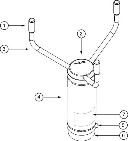
Figure 1 WMT700 Wind Sensor
The following numbers refer to Figure 1 above:
The array consists of 1, 2, and 3:
1= Transducers (3 pcs)
2= Top of WMT700. There is a north arrow on top of WMT700.
3= Transducer arms (3 pcs)
4= Enclosure
5= Mounting screw
6= Mounting adapter
7= Type label
18 ___________________________________________________________________ M211095EN-E
Chapter 2 ___________________________________________________________ Product Overview
1104-065
Figure 2 WMT700 Wind Sensor from Below
The following numbers refer to Figure 2 above:
1= Waterproof vent
2= Mounting adapter screw (3 pcs; use Allen key 4 mm)
3= 17-pin M23 male connector
NOTE |
Do not open the sensor. There are no user-serviceable parts inside. |
|
|
VAISALA________________________________________________________________________ 19
User's Guide ______________________________________________________________________
1104-064
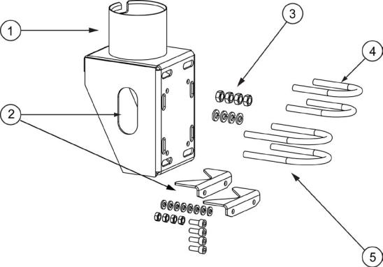
Figure 3 FIX70 Mounting Kit
The following numbers refer to Figure 3 above:
FIX70 consists of :
1= Fix body
2= Removable mast guide with mounting hardware
3= Mounting hardware (M6 nuts, washers)
4= U bolts for ø30 mm mast (2 pcs)
5= U bolts for ø60 mm mast (2 pcs)
20 ___________________________________________________________________ M211095EN-E
Chapter 2 ___________________________________________________________ Product Overview
1305-001
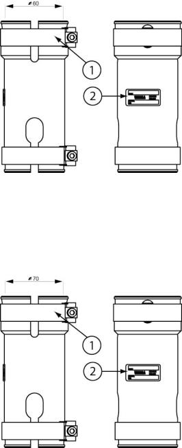
Figure 4 WS425FIX60-POM
The following numbers refer to Figure 4 above:
1 |
= |
Clamp |
2 |
= |
Label |
1305-002
Figure 5 WMT70FIX60-POM
The following numbers refer to Figure 5 above:
1 |
= |
Clamp |
2 |
= |
Label |
VAISALA________________________________________________________________________ 21
User's Guide ______________________________________________________________________
1305-003
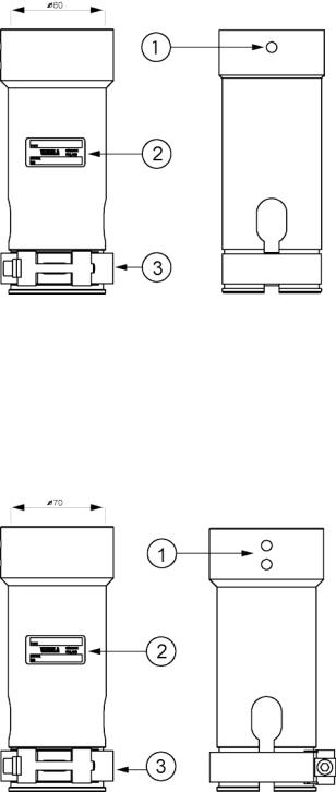
Figure 6 WS425FIX60-RST and WS425FIX60
The following numbers refer to Figure 6 above:
1= Screw hole
2= Label
3= Clamp
1305-004
Figure 7 WMT70FIX60-RST
The following numbers refer to Figure 7 above:
1= Screw holes
2= Label
3= Clamp
22 ___________________________________________________________________ M211095EN-E

Chapter 2 ___________________________________________________________ Product Overview
Ordering Options
A WMT700 unit can be configured by ordering options to suit versatile customer needs. You can reconfigure the following options:
-Digital communication interface
-Digital communication profile
-Digital communication units
-Analog output signals for wind speed channel
-Analog output signals for wind direction channel
Measurement Range
Ordering option 1, Measurement Range, defines the wind speed operation range for the sensor. The maximum reported value of wind speed 40, 65, or 75 m/s, depending on the selected option as shown in Table 5 below.
Table 5 |
Measurement Ranges of Different Sensor Types |
|
|
|
|
Sensor Type |
|
Measurement Range |
1 |
|
WMT701 up to 40 m/s |
2 |
|
WMT702 up to 65 m/s |
3 |
|
WMT703 up to 75 m/s |
A |
|
WMT701 up to 40 m/s + Accredited Wind Calibration |
B |
|
WMT702 up to 65 m/s + Accredited Wind Calibration |
C |
|
WMT703 up to 75 m/s + Accredited Wind Calibration |
Temperature Range
Ordering option 2, Temperature Range, defines the operating temperature range for the sensor as shown in Table 6 below.
Table 6 |
Temperature Ranges |
|
|
|
|
Option |
|
Temperature Range |
A |
|
-10 ... +60 °C |
B |
|
-40 ... +60 °C |
C |
|
-55 ... +70 °C |
Note that the temperature range is not connected to heating in any way. If you operate in a demanding environmental climate where ice accumulation is expected, Vaisala recommends that you use a heated sensor; see Option 4 in Table 7 on page 24.
VAISALA________________________________________________________________________ 23

User's Guide ______________________________________________________________________
Heating
Ordering option 3, Heating, defines if the sensor is equipped with extra heating for demanding environmental conditions. Option 4 providing full sensor heating is best suited for most demanding environments. Note that power consumption requirement depends on the selected heating option.
Table 7 |
Heating |
|
|
|
|
Option |
|
Heating |
1 |
|
Non-heated |
2 |
|
Heated transducers (Min. 30 W power supply is needed) |
3 |
|
Heated transducers and arms (Min. 200 W needed) |
4 |
|
Heated transducers, arms, and body (Min. 350 W needed) |
Digital Communication Interface
Ordering option 4, Digital Communication Interface, defines the serial line physical interface. Four different standard communication interfaces are available.
Table 8 |
Digital Communication Interface |
|
|
|
|
Option |
|
Hardware Interface |
A |
|
RS-485 isolated (1 pair) |
B |
|
RS-422 isolated |
C |
|
RS-232 isolated |
D |
|
SDI-12 isolated |
24 ___________________________________________________________________ M211095EN-E

Chapter 2 ___________________________________________________________ Product Overview
Digital Communication Profile
Ordering option 5, Digital Communication Profile, defines the communication protocol used for the sensor. WS425 options are usable and backwards compatible when replacing WS425 sensor with a WMT700 unit. MARINE and WIND TURBINE options are customer-specific profiles.
Table 9 |
Digital Communication Profile |
|
|
|
|
|
|
Option |
Communication Profile |
|
|
0 |
WMT70 - default mode |
9600, 8, N, 1 |
Polled |
1 |
WS425 - ASCII |
2400, 8, N, 1 |
Polled |
2 |
WS425 - NMEA Extended (v 0183) |
9600, 8, N, 1 |
Auto send 1/s |
3 |
WS425 - SDI-12 (v 1.3) |
1200, 7, E, 1 |
Polled |
4 |
WS425 - ASOS |
2400, 8, N, 1 |
Polled |
5 |
ROSA - MES12 |
9600, 8, N, 1 |
Polled |
6 |
US AWOS - NMEA Standard |
2400, 8, N, 1 |
Autosend 5/s |
7 |
FAA - Federal |
9600, 8, N, 1 |
Polled |
8 |
AWS520 - NMEA Extended (v 0183) |
4800, 8, N, 1 |
Auto send 1/s |
A |
MARINE1 (v 0183) |
4800, 8, N, 1 |
Auto send 1/s |
B |
MARINE2 (v 0183) |
9600, 8, N, 1 |
Auto send 1/s |
C |
WIND TURBINE1 (default) |
9600, 8, N, 1 |
Polled |
D |
WIND TURBINE2 (v 0183) |
9600, 8, N, 1 |
Auto send 1/s |
Digital Communication Units
Ordering option 6, Unit Definition for Digital Communication, offers four different digital communication options.
Table 10 Digital Communication Options
Option Unit Used
AMeters per second
BKnots
CMiles per hour
DKilometers per hour
VAISALA________________________________________________________________________ 25

User's Guide ______________________________________________________________________
Analog Output Signal for Wind Speed Channel
Ordering option 7, Analog Output for Wind Speed, can be disabled or factory-configured for 8 different modes. WS425 options are usable and backwards compatible when replacing WS425 sensor with a WMT700 unit.
Table 11 |
Output Configuration |
|
|
|
|
Option |
|
Output Configuration |
0 |
|
Disabled |
1 |
|
Voltage output 100 mV/m/s |
|
|
0 mV = 0 m/s |
|
|
4000 mV = 40 m/s (WMT701 maximum wind speed) |
|
|
6500 mV = 65 m/s (WMT702 maximum wind speed) |
|
|
7500 mV = 75 m/s (WMT703 maximum wind speed) |
2 |
|
Reserved for future use |
3 |
|
Current output 4…20 mA, offset 4 mA |
|
|
4 mA = 0 m/s |
|
|
20 mA = 40 m/s (WMT701, 0.4 mA/m/s) |
|
|
20 mA = 65 m/s (WMT702, 0.24615 mA/m/s) |
|
|
20 mA = 75 m/s (WMT703, 0.21333 mA/m/s) |
|
|
Error indication sets output to 2 mA |
4 |
|
Current output 0.2 mA/m/s |
|
|
0 mA = 0 m/s |
|
|
8 mA = 40 m/s (WMT701 maximum wind speed) |
|
|
13 mA = 65 m/s (WMT702 maximum wind speed) |
|
|
15 mA = 75 m/s (WMT703 maximum wind speed) |
5 |
|
Reserved for future use |
6 |
|
Frequency output 10 Hz/m/s |
|
|
0 Hz = 0 m/s |
|
|
400 Hz = 40 m/s (WMT701 maximum wind speed) |
|
|
650 Hz = 65 m/s (WMT702 maximum wind speed) |
|
|
750 Hz = 75 m/s (WMT703 maximum wind speed) |
7 |
|
WS425 voltage output 8 mV/mph |
|
|
0 mV = 0 m/s |
|
|
716 mV = 89.5 mph (WMT701 maximum wind speed) |
|
|
1116 mV = 145 mph (WMT702 maximum wind speed) |
|
|
1344 mV = 168 mph (WMT703 maximum wind speed) |
8 |
|
WS425 frequency output 5 Hz/mph |
|
|
0 Hz = 0 m/s |
|
|
447.5 Hz = 89.5 mph (WMT701 maximum wind speed) |
|
|
725 Hz = 145 mph (WMT702 maximum wind speed) |
|
|
840 Hz = 168 mph (WMT703 maximum wind speed) |
9 |
|
Reserved for future use |
A |
|
Push up output, 10 Hz/m/s |
|
|
0 Hz = 0 m/s |
|
|
400 Hz = 40 m/s (WMT701 maximum wind speed) |
|
|
650 Hz = 65 m/s (WMT702 maximum wind speed) |
|
|
750 Hz = 75 m/s (WMT703 maximum wind speed) |
B |
|
Pull down output 10 Hz/m/s |
|
|
0 Hz = 0 m/s |
|
|
400 Hz = 40 m/s (WMT701 maximum wind speed) |
|
|
650 Hz = 65 m/s (WMT702 maximum wind speed) |
|
|
750 Hz = 75 m/s (WMT703 maximum wind speed) |
26 ___________________________________________________________________ M211095EN-E

Chapter 2 ___________________________________________________________ Product Overview
Analog Output Signal for Wind Direction
Channel
Ordering option 8 defines Analog Output Signal for Wind Direction.WS425 Potentiometer output is backward compatible when replacing WS425 with a WMT700 unit. For different wind speed and direction representations, see Figure 13 on page 39. Note that the wind direction offset must be 0 for the for the readings to correspond with Figure 13.
Table 12 |
Analog Output Signal for Wind Direction |
|
|
|
|
Selection |
|
Output Configuration |
0 |
|
Disabled |
A |
|
Voltage output 20 mV/degree |
|
|
0 mV = 0 degree |
|
|
7200 mV = 360 degree |
B |
|
Reserved for future use |
C |
|
Reserved for future use |
D |
|
Current output 50 uA/degree |
|
|
0 uA = 0 degree |
|
|
18 mA = 360 degree |
E |
|
Current output 4…20 mA (44.444 uA/degree) |
|
|
4 mA = 0 degree |
|
|
20 mA = 360 degree km/h |
F |
|
WS425 Potentiometer output |
|
|
0% of Vref = 0 degree |
|
|
100% of Vref = 360 degree |
Connection Cables
Ordering option 9 defines connection cables. There are several different cables of different lengths for different purposes, as shown in Table 13 on page 28.
VAISALA________________________________________________________________________ 27

User's Guide ______________________________________________________________________
Table 13 |
Analog Output Configuration |
|
|
|
|
Selection |
|
Cable type |
1 |
|
No cables |
2 |
|
Cable 2 m, cable connector, open leads on one end |
3 |
|
Cable 10 m, cable connector, open leads on one end |
4 |
|
MAWS cable 10 m |
5 |
|
AWS520 cable 10 m. Shield connected to PE pin |
6 |
|
Adapter cable for WS425 serial |
7 |
|
Adapter cable for WS425 analog frequency output |
8 |
|
RS485 cable 2 m, cable connector, open leads on one |
|
|
end |
9 |
|
RS485 Cable 10 m, cable connector, open leads on one |
|
|
end |
A |
|
Adapter cable for WS425 analog voltage output |
B |
|
AWS520 cable 10 m. Shield not connected to PE pin. |
C |
|
ROSA analog cable 10 m, cable connector, open leads on |
|
|
one end |
D |
|
Junction Box with Cable 2 m |
E |
|
Cable 15 m, cable connector, open leads on one end |
F |
|
Cable 26 m, cable connector, open leads on one end |
Mounting Adapters
Ordering option 10 defines mounting adapters. There are several different mounting adapters for different purposes, as shown in Table 14 below.
|
Table 14 |
Mounting Adapters |
|
|
|
|
|
|
|
|
Option |
|
Adapter Type |
|
|
A |
|
Adapter 228869 only. Standard adapter, no fix |
|
|
B |
|
Adapter 228869 with WMT70FIX70 fixing mechanics. Also |
|
|
|
|
suitable for inverted mounting. Standard adapter for |
|
|
|
|
general purpose |
|
|
C |
|
Adapter 228869 with WMT700FIX60-POM. Standard |
|
|
|
|
adapter with plastic fix for 60 mm pole |
|
|
D |
|
Adapter 228869 with WMT700FIX60-RST Standard |
|
|
|
|
adapter with stainless steel fix for 60 mm pole |
|
|
E |
|
Adapter 22877 only (used for old WS425 |
|
|
|
|
FIX30/WS425FIX60), WS425-compatible adapter, no fix |
|
|
|
|
|
|
NOTE |
Ordering option 11 is reserved for future use. |
|
||
|
|
|
|
|
|
Accessories |
|
||
|
Ordering option 12 defines WMT700 accessories. |
|
||
|
Table 15 |
Accessories |
|
|
|
|
|
|
|
|
Option |
|
Accessories |
|
|
A |
|
No accessories |
|
|
B |
|
Bird cage WMT70BirdKit |
|
28 ___________________________________________________________________ M211095EN-E
Loading...