


 Loading...
USER'S GUIDE
Vaisala Weather Transmitter
WXT520
M210906EN-C
PUBLISHED BY |
|
|
|
Vaisala Oyj |
Phone (int.): |
+358 |
9 8949 1 |
P.O. Box 26 |
Fax: |
+358 |
9 8949 2227 |
FI-00421 Helsinki |
|
|
|
Finland |
|
|
|
Visit our Internet pages at http://www.vaisala.com/
© Vaisala 2012
No part of this manual may be reproduced in any form or by any means, electronic or mechanical (including photocopying), nor may its contents be communicated to a third party without prior written permission of the copyright holder.
The contents are subject to change without prior notice.
Please observe that this manual does not create any legally binding obligations for Vaisala towards the customer or end user. All legally binding commitments and agreements are included exclusively in the applicable supply contract or Conditions of Sale.
________________________________________________________________________________
Table of Contents
CHAPTER 1
GENERAL INFORMATION . . . . . . . . . . . . . . . . . . . . . . . . . . . . . . . . . . . . .11
About This Manual . . . . . . . . . . . . . . . . . . . . . . . . . . . . . . . .11
Contents of This Manual . . . . . . . . . . . . . . . . . . . . . . . . . . 11
General Safety Considerations . . . . . . . . . . . . . . . . . . . . .12
Feedback . . . . . . . . . . . . . . . . . . . . . . . . . . . . . . . . . . . . . . 13
ESD Protection . . . . . . . . . . . . . . . . . . . . . . . . . . . . . . . . . . .13
Recycling . . . . . . . . . . . . . . . . . . . . . . . . . . . . . . . . . . . . . . . .13
Trademarks . . . . . . . . . . . . . . . . . . . . . . . . . . . . . . . . . . . . . .14
License Agreement . . . . . . . . . . . . . . . . . . . . . . . . . . . . . . . . 14
Regulatory Compliance . . . . . . . . . . . . . . . . . . . . . . . . . . . .14
Warranty . . . . . . . . . . . . . . . . . . . . . . . . . . . . . . . . . . . . . . . .15
CHAPTER 2
PRODUCT OVERVIEW . . . . . . . . . . . . . . . . . . . . . . . . . . . . . . . . . . . . . . .17
Weather Transmitter WXT520 . . . . . . . . . . . . . . . . . . . . . . .17
Heating Function . . . . . . . . . . . . . . . . . . . . . . . . . . . . . . . .18 Optional Software for Easy Settings . . . . . . . . . . . . . . . . . 18
WXT520 Transmitter Components . . . . . . . . . . . . . . . . . . .19
CHAPTER 3
FUNCTIONAL DESCRIPTION . . . . . . . . . . . . . . . . . . . . . . . . . . . . . . . . . .25
Wind Measurement Principle . . . . . . . . . . . . . . . . . . . . . . . .25
Precipitation Measurement Principle . . . . . . . . . . . . . . . . .27
PTU Measurement Principle . . . . . . . . . . . . . . . . . . . . . . . . . 29
Heating (Optional) . . . . . . . . . . . . . . . . . . . . . . . . . . . . . . . . .29
CHAPTER 4
INSTALLATION . . . . . . . . . . . . . . . . . . . . . . . . . . . . . . . . . . . . . . . . . . . . .31
Unpacking the Transmitter . . . . . . . . . . . . . . . . . . . . . . . . . .31
Selecting the Location . . . . . . . . . . . . . . . . . . . . . . . . . . . . .32
Installation Procedure . . . . . . . . . . . . . . . . . . . . . . . . . . . . .34
Mounting . . . . . . . . . . . . . . . . . . . . . . . . . . . . . . . . . . . . . . 34
Mounting to Vertical Pole Mast . . . . . . . . . . . . . . . . . . 34
Mounting with Mounting Kit (Optional). . . . . . . . . . . . . 35
Mounting To Horizontal Cross Arm . . . . . . . . . . . . . . . 37
Grounding the WXT520 . . . . . . . . . . . . . . . . . . . . . . . . . . . 38
Grounding Using the Bushing and Grounding Kit . . . . 38
Marine Grounding Jumper . . . . . . . . . . . . . . . . . . . . . . 39
VAISALA________________________________________________________________________ 1
________________________________________________________________________________
Aligning WXT520 . . . . . . . . . . . . . . . . . . . . . . . . . . . . . . .41
Compass Alignment. . . . . . . . . . . . . . . . . . . . . . . . . . . 41
Wind Direction Offset . . . . . . . . . . . . . . . . . . . . . . . . . . 42
CHAPTER 5
WIRING AND POWER MANAGEMENT . . . . . . . . . . . . . . . . . . . . . . . . . . .43
Power Supplies . . . . . . . . . . . . . . . . . . . . . . . . . . . . . . . . . . .43
Wiring Using the 8-pin M12 Connector . . . . . . . . . . . . . . . .46
External Wiring . . . . . . . . . . . . . . . . . . . . . . . . . . . . . . . . . .46
Internal Wiring . . . . . . . . . . . . . . . . . . . . . . . . . . . . . . . . . .47
Wiring Using the Screw Terminals . . . . . . . . . . . . . . . . . . .48
Data Communication Interfaces . . . . . . . . . . . . . . . . . . . . .50
Power Management . . . . . . . . . . . . . . . . . . . . . . . . . . . . . . . .51
CHAPTER 6 |
|
CONNECTION OPTIONS . . . . . . . . . . . . . . . . . . . . . . . . . . . . . . . . . . . . . . |
55 |
Communication Protocols . . . . . . . . . . . . . . . . . . . . . . . . . . |
55 |
Connection cables . . . . . . . . . . . . . . . . . . . . . . . . . . . . . . . . |
56 |
Installing the Driver for the USB Cable . . . . . . . . . . . . . . . |
57 |
Service Cable Connection . . . . . . . . . . . . . . . . . . . . . . . . . .58
Connection Through M12 Bottom Connector or
Screw Terminal . . . . . . . . . . . . . . . . . . . . . . . . . . . . . . . . .59
Communication Setting Commands . . . . . . . . . . . . . . . . . .60
Checking the Current Communication Settings (aXU) . . . .60
Setting Fields . . . . . . . . . . . . . . . . . . . . . . . . . . . . . . . . . . .61
Changing the Communication Settings (aXU) . . . . . . . . . .63
CHAPTER 7
GETTING THE DATA MESSAGES . . . . . . . . . . . . . . . . . . . . . . . . . . . . . .65
General Commands . . . . . . . . . . . . . . . . . . . . . . . . . . . . . . .66
Reset (aXZ) . . . . . . . . . . . . . . . . . . . . . . . . . . . . . . . . . . . .66 Precipitation Counter Reset (aXZRU) . . . . . . . . . . . . . . . .67 Precipitation Intensity Reset (aXZRI) . . . . . . . . . . . . . . . . .68 Measurement Reset (aXZM) . . . . . . . . . . . . . . . . . . . . . . .69
ASCII Protocol . . . . . . . . . . . . . . . . . . . . . . . . . . . . . . . . . . . .70
Abbreviations and Units . . . . . . . . . . . . . . . . . . . . . . . . . . .70 Device Address (?) . . . . . . . . . . . . . . . . . . . . . . . . . . . . . . .71 Acknowledge Active Command (a) . . . . . . . . . . . . . . . . . .71 Wind Data Message (aR1) . . . . . . . . . . . . . . . . . . . . . . . . .72 Pressure, Temperature and Humidity Data Message
(aR2) . . . . . . . . . . . . . . . . . . . . . . . . . . . . . . . . . . . . . . . . .73 Precipitation Data Message (aR3) . . . . . . . . . . . . . . . . . . .74 Supervisor Data Message (aR5) . . . . . . . . . . . . . . . . . . . .75 Combined Data Message (aR) . . . . . . . . . . . . . . . . . . . . . .76 Composite Data Message Query (aR0) . . . . . . . . . . . . . . .76 Polling with CRC . . . . . . . . . . . . . . . . . . . . . . . . . . . . . . . .77 Automatic Mode . . . . . . . . . . . . . . . . . . . . . . . . . . . . . . . . .79 Automatic Composite Data Message (aR0) . . . . . . . . . . . .79
2 _______________________________________________________________________________
________________________________________________________________________________
SDI-12 Protocol . . . . . . . . . . . . . . . . . . . . . . . . . . . . . . . . . . . 80
Address Query Command (?) . . . . . . . . . . . . . . . . . . . . . .81 Acknowledge Active Command (a) . . . . . . . . . . . . . . . . . . 81 Change Address Command (aAb) . . . . . . . . . . . . . . . . . . . 82 Send Identification Command (aI) . . . . . . . . . . . . . . . . . . . 83 Start Measurement Command (aM) . . . . . . . . . . . . . . . . . 83 Start Measurement Command with CRC (aMC) . . . . . . . .85 Start Concurrent Measurement (aC) . . . . . . . . . . . . . . . . . 85 Start Concurrent Measurement with CRC (aCC) . . . . . . . .86 Send Data Command (aD) . . . . . . . . . . . . . . . . . . . . . . . .87 Examples of aM, aC and aD Commands . . . . . . . . . . . . . . 88 Continuous Measurement (aR) . . . . . . . . . . . . . . . . . . . . .90 Continuous Measurement with CRC (aRC) . . . . . . . . . . . . 92 Start Verification Command (aV) . . . . . . . . . . . . . . . . . . . . 92
NMEA 0183 V3.0 Protocol . . . . . . . . . . . . . . . . . . . . . . . . . . .93
Device Address (?) . . . . . . . . . . . . . . . . . . . . . . . . . . . . . . 93 Acknowledge Active Command (a) . . . . . . . . . . . . . . . . . . 94 MWV Wind Speed and Direction Query . . . . . . . . . . . . . . .94 XDR Transducer Measurement Query . . . . . . . . . . . . . . . 96 TXT Text Transmission . . . . . . . . . . . . . . . . . . . . . . . . . .104 Automatic Mode . . . . . . . . . . . . . . . . . . . . . . . . . . . . . . . . 106 Automatic Composite Data Message (aR0) . . . . . . . . . . . 106
CHAPTER 8
SENSOR AND DATA MESSAGE SETTINGS . . . . . . . . . . . . . . . . . . . . .107
Wind Sensor . . . . . . . . . . . . . . . . . . . . . . . . . . . . . . . . . . . .107
Checking the Settings (aWU) . . . . . . . . . . . . . . . . . . . . . .107
Setting Fields . . . . . . . . . . . . . . . . . . . . . . . . . . . . . . . . . . 109
Changing the Settings (aWU) . . . . . . . . . . . . . . . . . . . . .111
Pressure, Temperature, and Humidity Sensors . . . . . . . .113
Checking the Settings (aTU) . . . . . . . . . . . . . . . . . . . . . . 113
Setting Fields . . . . . . . . . . . . . . . . . . . . . . . . . . . . . . . . . . 114
Changing the Settings (aTU) . . . . . . . . . . . . . . . . . . . . . .115
Precipitation Sensor . . . . . . . . . . . . . . . . . . . . . . . . . . . . . .117
Checking the Settings (aRU) . . . . . . . . . . . . . . . . . . . . . .117
Setting Fields . . . . . . . . . . . . . . . . . . . . . . . . . . . . . . . . . . 118
Changing the Settings (aRU) . . . . . . . . . . . . . . . . . . . . . .121
Supervisor Message . . . . . . . . . . . . . . . . . . . . . . . . . . . . . .123
Checking the Settings (aSU) . . . . . . . . . . . . . . . . . . . . . . 123
Setting Fields . . . . . . . . . . . . . . . . . . . . . . . . . . . . . . . . . . 124
Changing the Settings (aSU) . . . . . . . . . . . . . . . . . . . . . .125
Composite Data Message (aR0) . . . . . . . . . . . . . . . . . . . . .127
CHAPTER 9
MAINTENANCE . . . . . . . . . . . . . . . . . . . . . . . . . . . . . . . . . . . . . . . . . . . .129
Cleaning . . . . . . . . . . . . . . . . . . . . . . . . . . . . . . . . . . . . . . . .129
Replacing the PTU Module . . . . . . . . . . . . . . . . . . . . . . . . .130
Factory Calibration and Repair Service . . . . . . . . . . . . . .131
Vaisala Service Centers . . . . . . . . . . . . . . . . . . . . . . . . . . .131
VAISALA________________________________________________________________________ 3
________________________________________________________________________________
CHAPTER 10
TROUBLESHOOTING . . . . . . . . . . . . . . . . . . . . . . . . . . . . . . . . . . . . . . .133
Self-Diagnostics . . . . . . . . . . . . . . . . . . . . . . . . . . . . . . . . .135
Error Messaging/Text Messages . . . . . . . . . . . . . . . . . . .135
Rain and Wind Sensor Heating Control . . . . . . . . . . . . . .137
Operating Voltage Control . . . . . . . . . . . . . . . . . . . . . . . .137
Technical Support . . . . . . . . . . . . . . . . . . . . . . . . . . . . . .137
CHAPTER 11
TECHNICAL SPECIFICATIONS . . . . . . . . . . . . . . . . . . . . . . . . . . . . . . . .139
Performance . . . . . . . . . . . . . . . . . . . . . . . . . . . . . . . . . . . .139
Inputs and Outputs . . . . . . . . . . . . . . . . . . . . . . . . . . . . . . .142
Operating Conditions . . . . . . . . . . . . . . . . . . . . . . . . . . . . .143
Materials . . . . . . . . . . . . . . . . . . . . . . . . . . . . . . . . . . . . . . . .144
General . . . . . . . . . . . . . . . . . . . . . . . . . . . . . . . . . . . . . . . . .144
Options and Accessories . . . . . . . . . . . . . . . . . . . . . . . . . .145
Dimensions (mm/inch) . . . . . . . . . . . . . . . . . . . . . . . . . . . .146
APPENDIX A
NETWORKING . . . . . . . . . . . . . . . . . . . . . . . . . . . . . . . . . . . . . . . . . . . . .149 Connecting Several WXT520s on the Same Bus . . . . . . .149
SDI-12 Serial Interface . . . . . . . . . . . . . . . . . . . . . . . . . . . .149
Wiring . . . . . . . . . . . . . . . . . . . . . . . . . . . . . . . . . . . . . . . .149 Communication Protocol . . . . . . . . . . . . . . . . . . . . . . . . .150
RS-485 Serial Interface . . . . . . . . . . . . . . . . . . . . . . . . . . . .151
Wiring . . . . . . . . . . . . . . . . . . . . . . . . . . . . . . . . . . . . . . . .151 Communication Protocol . . . . . . . . . . . . . . . . . . . . . . . . .151 ASCII, Polled . . . . . . . . . . . . . . . . . . . . . . . . . . . . . . . . . .151 NMEA 0183 v3.0, Query . . . . . . . . . . . . . . . . . . . . . . . . .152 NMEA 0183 v3.0 Query with ASCII Query Commands . .154
APPENDIX B
SDI-12 PROTOCOL . . . . . . . . . . . . . . . . . . . . . . . . . . . . . . . . . . . . . . . . .157
SDI-12 Electrical Interface . . . . . . . . . . . . . . . . . . . . . . . . .157
SDI-12 Communications Protocol . . . . . . . . . . . . . . . . . .158
SDI-12 Timing . . . . . . . . . . . . . . . . . . . . . . . . . . . . . . . . .159
APPENDIX C
CRC-16 COMPUTATION . . . . . . . . . . . . . . . . . . . . . . . . . . . . . . . . . . . . .161
Encoding the CRC as ASCII Characters . . . . . . . . . . . . . .162
NMEA 0183 v3.0 Checksum Computation . . . . . . . . . . . .162
APPENDIX D
WIND MEASUREMENT AVERAGING METHOD . . . . . . . . . . . . . . . . . . .163
4 _______________________________________________________________________________
________________________________________________________________________________
APPENDIX E
FACTORY CONFIGURATIONS . . . . . . . . . . . . . . . . . . . . . . . . . . . . . . . .165
General Unit Settings . . . . . . . . . . . . . . . . . . . . . . . . . . . . .166
Wind Configuration Settings . . . . . . . . . . . . . . . . . . . . . . .166
PTU Configuration Settings . . . . . . . . . . . . . . . . . . . . . . . .167
Rain Configuration Settings . . . . . . . . . . . . . . . . . . . . . . . . 167
Supervisor Settings . . . . . . . . . . . . . . . . . . . . . . . . . . . . . .167
VAISALA________________________________________________________________________ 5
________________________________________________________________________________
6 _______________________________________________________________________________
________________________________________________________________________________
List of Figures
Figure 1 Vaisala Weather Transmitter WXT520. . . . . . . . . . . . . . . . . . . 17 Figure 2 Main Components of Weather Transmitter WXT520 . . . . . . . .19 Figure 3 Cut Away View. . . . . . . . . . . . . . . . . . . . . . . . . . . . . . . . . . . . .20 Figure 4 Bottom of Transmitter. . . . . . . . . . . . . . . . . . . . . . . . . . . . . . . . 21 Figure 5 Mounting Kit (Optional) . . . . . . . . . . . . . . . . . . . . . . . . . . . . . . 22 Figure 6 USB Cables (optional). . . . . . . . . . . . . . . . . . . . . . . . . . . . . . .22 Figure 7 Bird Spike Kit (optional) . . . . . . . . . . . . . . . . . . . . . . . . . . . . . . 23 Figure 8 Surge Protector (optional) . . . . . . . . . . . . . . . . . . . . . . . . . . . . 24 Figure 9 Heating Control . . . . . . . . . . . . . . . . . . . . . . . . . . . . . . . . . . . . 30 Figure 10 Recommended Mast Location in an Open Area . . . . . . . . . . .32 Figure 11 Recommended Mast Length on Top of a Building. . . . . . . . . .33 Figure 12 Location of Fixing Screw . . . . . . . . . . . . . . . . . . . . . . . . . . . . .35 Figure 13 Mounting WXT520 to Pole Mast Using Optional Mounting
Kit. . . . . . . . . . . . . . . . . . . . . . . . . . . . . . . . . . . . . . . . . . . . . . .36 Figure 14 Mounting WXT520 to Cross Arm (L-Profile). . . . . . . . . . . . . . .37 Figure 15 Mounting Bolt Location in Cross Arm. . . . . . . . . . . . . . . . . . . . 38 Figure 16 Grounding Using the Bushing and Grounding Kit . . . . . . . . . . 39 Figure 17 Grounding Jumper Location. . . . . . . . . . . . . . . . . . . . . . . . . . . 40 Figure 18 Sketch of Magnetic Declination . . . . . . . . . . . . . . . . . . . . . . . .41 Figure 19 Wind Direction Offset . . . . . . . . . . . . . . . . . . . . . . . . . . . . . . . . 42 Figure 20 Average Operational Current Consumption (with 4Hz
Wind Sensor Sampling) . . . . . . . . . . . . . . . . . . . . . . . . . . . . . . 44 Figure 21 Heating Current and Power vs Vh . . . . . . . . . . . . . . . . . . . . . .45 Figure 22 Pins of 8-pin M12 Connector . . . . . . . . . . . . . . . . . . . . . . . . . . 46 Figure 23 Internal Wiring . . . . . . . . . . . . . . . . . . . . . . . . . . . . . . . . . . . . .47 Figure 24 Screw Terminal Block . . . . . . . . . . . . . . . . . . . . . . . . . . . . . . . 48 Figure 25 Data Communication Interfaces. . . . . . . . . . . . . . . . . . . . . . . . 50 Figure 26 Replacing the PTU Module . . . . . . . . . . . . . . . . . . . . . . . . . .130 Figure 27 Accuracy Over Temperature Range . . . . . . . . . . . . . . . . . . . 140 Figure 28 WXT520 Dimensions, Side View . . . . . . . . . . . . . . . . . . . . . .146 Figure 29 WXT520 Dimensions, Top and Bottom View . . . . . . . . . . . . . 147 Figure 30 Mounting Kit Dimensions . . . . . . . . . . . . . . . . . . . . . . . . . . . .148 Figure 31 Timing Diagram . . . . . . . . . . . . . . . . . . . . . . . . . . . . . . . . . . . 159 Figure 32 Wind Measurement Averaging Method . . . . . . . . . . . . . . . . . 164
VAISALA________________________________________________________________________ 7
________________________________________________________________________________
8 _______________________________________________________________________________
________________________________________________________________________________
List of Tables
Table 1 Pin-outs for WXT520 Serial Interfaces and Power Supplies . . . . 46 Table 2 Screw Terminal Pin-outs for WXT520 Serial Interfaces and
Power Supplies . . . . . . . . . . . . . . . . . . . . . . . . . . . . . . . . . . . . . . 49 Table 3 Available Serial Communication Protocols . . . . . . . . . . . . . . . . . 55 Table 4 Connection Cable Options . . . . . . . . . . . . . . . . . . . . . . . . . . . . . . 56 Table 5 Default Serial Communication Settings for M12/Screw
Terminal Connection . . . . . . . . . . . . . . . . . . . . . . . . . . . . . . . . . .59 Table 6 Abbreviations and Units . . . . . . . . . . . . . . . . . . . . . . . . . . . . . . . . 70 Table 7 Transducer IDs of the Measurement Parameters . . . . . . . . . . . . 98 Table 8 Transducer Table. . . . . . . . . . . . . . . . . . . . . . . . . . . . . . . . . . . . . 104 Table 9 Data Validation. . . . . . . . . . . . . . . . . . . . . . . . . . . . . . . . . . . . . . .133 Table 10 Communication Problems . . . . . . . . . . . . . . . . . . . . . . . . . . . . . . 134 Table 11 Error Messaging/Text Messages Table . . . . . . . . . . . . . . . . . . . .136 Table 12 Barometric Pressure . . . . . . . . . . . . . . . . . . . . . . . . . . . . . . . . . .139 Table 13 Air Temperature . . . . . . . . . . . . . . . . . . . . . . . . . . . . . . . . . . . . . .139 Table 14 Wind. . . . . . . . . . . . . . . . . . . . . . . . . . . . . . . . . . . . . . . . . . . . . . . 140 Table 15 Relative Humidity . . . . . . . . . . . . . . . . . . . . . . . . . . . . . . . . . . . . . 140 Table 16 Precipitation . . . . . . . . . . . . . . . . . . . . . . . . . . . . . . . . . . . . . . . . .141 Table 17 Inputs and Outputs. . . . . . . . . . . . . . . . . . . . . . . . . . . . . . . . . . . .142 Table 18 Operating Conditions . . . . . . . . . . . . . . . . . . . . . . . . . . . . . . . . . . 143 Table 19 Electromagnetic Compatibility . . . . . . . . . . . . . . . . . . . . . . . . . . . 143 Table 20 Materials . . . . . . . . . . . . . . . . . . . . . . . . . . . . . . . . . . . . . . . . . . . 144 Table 21 General . . . . . . . . . . . . . . . . . . . . . . . . . . . . . . . . . . . . . . . . . . . . 144 Table 22 Options and Accessories . . . . . . . . . . . . . . . . . . . . . . . . . . . . . . .145 Table 23 General Unit Settings. . . . . . . . . . . . . . . . . . . . . . . . . . . . . . . . . . 166 Table 24 Wind Configuration Settings. . . . . . . . . . . . . . . . . . . . . . . . . . . . . 166 Table 25 PTU Configuration Settings . . . . . . . . . . . . . . . . . . . . . . . . . . . . .167 Table 26 Rain Configuration Settings . . . . . . . . . . . . . . . . . . . . . . . . . . . . . 167 Table 27 General Unit Settings. . . . . . . . . . . . . . . . . . . . . . . . . . . . . . . . . . 167
VAISALA________________________________________________________________________ 9
________________________________________________________________________________
10 ______________________________________________________________________________
Chapter 1 ________________________________________________________ General Information
CHAPTER 1
GENERAL INFORMATION
This chapter provides general notes for the product.
About This Manual
This manual provides information for installing, operating, and maintaining Vaisala Weather Transmitter WXT520.
Contents of This Manual
This manual consists of the following chapters:
-Chapter 1, General Information: This chapter provides general notes for the product.
-Chapter 2, Product Overview: This chapter introduces the unique features and advantages of the Vaisala Weather Transmitter WXT520.
-Chapter 3, Functional Description: This chapter describes the measurement principles and heating function of Weather Transmitter WXT520.
-Chapter 4, Installation: This chapter provides you with information that is intended to help you install Weather Transmitter WXT520.
VAISALA_______________________________________________________________________ 11
User’s Guide ______________________________________________________________________
- Chapter 5, Wiring and Power Management: This chapter provides you with instructions on how to connect the power supply and the serial interfaces, and how to manage and estimate the power consumption.
- Chapter 6, Connection Options: This chapter contains instructions for configuring the communication with the transmitter.
- Chapter 7, Getting the Data Messages: This chapter presents the general and data message commands.
- Chapter 8, Sensor and Data Message Settings: This chapter presents the sensor configuration and data message formatting commands for all communications protocols: ASCII, NMEA 0183 and SDI-12.
- Chapter 9, Maintenance: This chapter contains instructions for the basic maintenance of Weather Transmitter WXT520 and contact information for Vaisala Service Centers.
- Chapter 10, Troubleshooting: This chapter describes common problems, their probable causes and remedies, and includes contact information for technical support.
- Chapter 11, Technical Specifications: This chapter provides the technical data of Weather Transmitter WXT520.
|
|
|
General Safety Considerations |
|
|
|
Throughout the manual, important safety considerations are highlighted |
|
|
|
as follows: |
|
|
|
|
|
|
WARNING |
Warning alerts you to a serious hazard. If you do not read and follow |
|
|
|
instructions very carefully at this point, there is a risk of injury or even |
|
|
|
death. |
|
|
|
|
|
|
|
|
|
|
|
|
|
|
CAUTION |
Caution warns you of a potential hazard. If you do not read and follow |
|
|
|
instructions carefully at this point, the product could be damaged or |
|
|
|
important data could be lost. |
|
|
|
|
|
|
|
|
|
|
NOTE |
Note highlights important information on using the product. |
|
|
|
|
12 __________________________________________________________________ M210906EN-C

Chapter 1 ________________________________________________________ General Information
Feedback
Vaisala Customer Documentation Team welcomes your comments and suggestions on the quality and usefulness of this publication. If you find errors or have other suggestions for improvement, please indicate the chapter, section, and page number. You can send comments to us by e-mail: manuals@vaisala.com.
ESD Protection
Electrostatic Discharge (ESD) can cause immediate or latent damage to electronic circuits. Vaisala products are adequately protected against ESD for their intended use. However, it is possible to damage the product by delivering electrostatic discharges when touching, removing, or inserting any objects inside the equipment housing.
To make sure you are not delivering high static voltages yourself:
-Handle ESD sensitive components on a properly grounded and protected ESD workbench. When this is not possible, ground yourself with a wrist strap and a resistive connection cord to the equipment chassis before touching the boards. When neither of the above is possible, at least touch a conductive part of the equipment chassis with your other hand before touching the boards.
-Always hold the boards by the edges and avoid touching the component contacts.
Recycling
Recycle all applicable material.
Dispose of batteries and the unit according to statutory regulations.
Do not dispose of with regular household refuse.
VAISALA_______________________________________________________________________ 13
User’s Guide ______________________________________________________________________
Trademarks
WINDCAP®, RAINCAP®, HUMICAP®, BAROCAP® and THERMOCAP® are registered trademarks of Vaisala. Microsoft®, Windows®, Windows 2000®, Windows XP®, Windows Server 2003®,
and Windows Vista® are registered trademarks of Microsoft Corporation in the United States and/or other countries.
License Agreement
All rights to any software are held by Vaisala or third parties. The customer is allowed to use the software only to the extent that is provided by the applicable supply contract or Software License Agreement.
Regulatory Compliance
The electromagnetic compatibility of the WXT520 has been tested according to the following product family standard:
EN 61326-1 Electrical equipment for measurement, control and laboratory use - EMC requirements - for use in industrial locations.
Additionally, the EMC specification of the WXT520 has been enhanced for marine use according to the following sections of the IEC 60945 Maritime Navigation and Radiocommunication Equipment and Systems - General requirements - Methods of testing and required test results:
-IEC 60945 / 61000-4-4 (EFT burst)
-IEC 60945 / 61000-4-2 (Marine ESD)
A summary of the test results is presented in Table 19 on page 143.
The WXT520 is in conformance with the provisions of the RoHS directive of the European Union:
Directive on the Restriction of the Use of Certain Hazardous Substances in Electrical and Electronic Equipment (2002/95/EC)
14 __________________________________________________________________ M210906EN-C
Chapter 1 ________________________________________________________ General Information
Warranty
Vaisala hereby represents and warrants all Products manufactured by Vaisala and sold hereunder to be free from defects in workmanship or material during a period of twelve (12) months from the date of delivery save for products for which a special warranty is given. If any Product proves however to be defective in workmanship or material within the period herein provided Vaisala undertakes to the exclusion of any other remedy to repair or at its own option replace the defective Product or part thereof free of charge and otherwise on the same conditions as for the original Product or part without extension to original warranty time. Defective parts replaced in accordance with this clause shall be placed at the disposal of Vaisala.
Vaisala also warrants the quality of all repair and service works performed by its employees to products sold by it. In case the repair or service works should appear inadequate or faulty and should this cause malfunction or nonfunction of the product to which the service was performed Vaisala shall at its free option either repair or have repaired or replace the product in question. The working hours used by employees of Vaisala for such repair or replacement shall be free of charge to the client. This service warranty shall be valid for a period of six (6) months from the date the service measures were completed.
This warranty is however subject to following conditions:
a)A substantiated written claim as to any alleged defects shall have been received by Vaisala within thirty (30) days after the defect or fault became known or occurred, and
b)The allegedly defective Product or part shall, should Vaisala so require, be sent to the works of Vaisala or to such other place as Vaisala may indicate in writing, freight and insurance prepaid and properly packed and labelled, unless Vaisala agrees to inspect and repair the Product or replace it on site.
This warranty does not however apply when the defect has been caused through
a)normal wear and tear or accident;
b)misuse or other unsuitable or unauthorized use of the Product or negligence or error in storing, maintaining or in handling the Product or any equipment thereof;
c)wrong installation or assembly or failure to service the Product or otherwise follow Vaisala's service instructions including any repairs or installation or assembly or service made by unauthorized personnel not approved by Vaisala or replacements with parts not manufactured or supplied by Vaisala;
d)modifications or changes of the Product as well as any adding to it without Vaisala's prior authorization;
e)other factors depending on the Customer or a third party.
Notwithstanding the aforesaid Vaisala's liability under this clause shall not apply to any defects arising out of materials, designs or instructions provided by the Customer.
This warranty is expressly in lieu of and excludes all other conditions, warranties and liabilities, express or implied, whether under law, statute or otherwise, including without limitation any implied warranties of merchantability or fitness for a particular purpose and all other obligations and liabilities of Vaisala or its representatives with respect to any defect or deficiency applicable to or resulting directly or indirectly from the Products supplied hereunder, which obligations and liabilities are hereby expressly cancelled and waived. Vaisala's liability shall under no circumstances exceed the invoice price of any Product for which a warranty claim is made, nor shall Vaisala in any circumstances be liable for lost profits or other consequential loss whether direct or indirect or for special damages.
VAISALA_______________________________________________________________________ 15
User’s Guide ______________________________________________________________________
16 __________________________________________________________________ M210906EN-C
Chapter 2 __________________________________________________________ Product Overview
CHAPTER 2
PRODUCT OVERVIEW
This chapter introduces the unique features and advantages of the
Vaisala Weather Transmitter WXT520.
Weather Transmitter WXT520
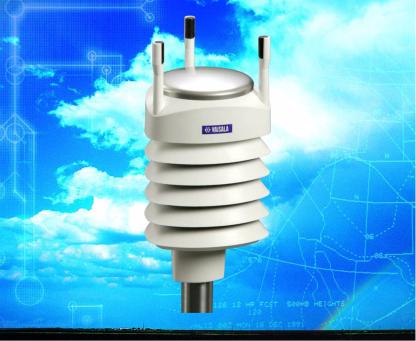
Figure 1 Vaisala Weather Transmitter WXT520
VAISALA_______________________________________________________________________ 17
User’s Guide ______________________________________________________________________
Weather Transmitter WXT520 is a small and lightweight transmitter that offers six weather parameters in one compact package. WXT520 measures wind speed and direction, precipitation, atmospheric pressure, temperature and relative humidity. The transmitter housing is IP65/IP66 rated.
WXT520 powers up with 5 ... 32 VDC and outputs serial data with a selectable communication protocol: SDI-12, ASCII automatic & polled and NMEA 0183 with query option. Four alternative serial interfaces are selectable: RS-232, RS-485, RS-422, and SDI-12. The transmitter is equipped with a 8-pin M12 connector for installation, and a 4-pin M8 connector for service use.
The following options are available:
-Heating function for the precipitation and wind sensors
-Service Pack 2: Windows® based Vaisala Configuration Tool software with USB service cable (1.4m)
-USB RS-232/RS-485 cable (1.4m)
-Mounting kit
-Bird spike kit
-Surge protector
-Shielded cables (2m, 10m, 40m)
-Bushing and grounding kit
Heating Function
To improve the accuracy of measurements an optional heating for the wind and precipitation sensors is available. More about heating in section Heating (Optional) on page 29.
The heating function option must be chosen when placing the order.
Optional Software for Easy Settings
Windows® based Vaisala Configuration Tool is a user friendly parameter setting software for WXT520. With this software tool you
can change the device and sensor settings easily in Windows® environment. See list of options and accessories in Table 22 on page 145.
18 __________________________________________________________________ M210906EN-C
Chapter 2 __________________________________________________________ Product Overview
WXT520 Transmitter Components
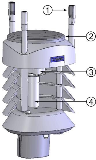
Figure 2 Main Components of Weather Transmitter WXT520
The following numbers refer to Figure 2 on page 19:
1= Top of the transmitter
2= Radiation shield
3= Bottom of the transmitter
4= Screw cover
VAISALA_______________________________________________________________________ 19
User’s Guide ______________________________________________________________________
Figure 3 Cut Away View
The following numbers refer to Figure 3 on page 20:
1= Wind transducers (3 pcs)
2= Precipitation sensor
3= Pressure sensor inside the PTU module
4= Humidity and temperature sensors inside the PTU module
20 __________________________________________________________________ M210906EN-C
Chapter 2 __________________________________________________________ Product Overview
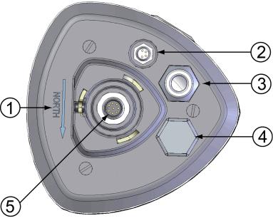
Figure 4 Bottom of Transmitter
The following numbers refer to Figure 4 on page 21:
1= Alignment direction sign
2= 4-pin M8 connector for Service Port
3= Water tight cable gland (optional, included in the Bushing and Grounding Kit)
4= Opening for cable gland (if unused, cover with a hexagonal plug)
5= 8-pin M12 connector for power/datacom cable (optional)
VAISALA_______________________________________________________________________ 21
User’s Guide ______________________________________________________________________
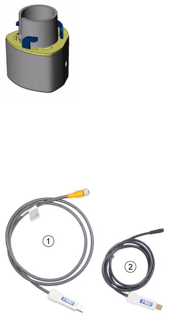
Figure 5 Mounting Kit (Optional)
The optional mounting kit can be used to ease the mounting of the WXT520 on a pole mast. When using the optional mounting kit, alignment is needed only when mounting for the first time. Using the mounting kit also improves the IP classification of the WXT520 to IP66. Without the mounting kit, the WXT520 is IP65.
Figure 6 USB Cables (optional)
The following numbers refer to Figure 6 on page 22:
1= USB RS-232/RS-485 cable with 8-pin M12 threaded connector (1.4 m)
2= USB service cable with 4-pin M8 snap-on connector (1.4 m)
The service cable, while connected between the service port and PC, forces the service port to RS-232 / 19200, 8, N, 1.
22 __________________________________________________________________ M210906EN-C
Chapter 2 __________________________________________________________ Product Overview
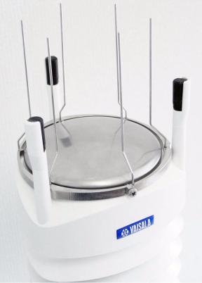
Figure 7 Bird Spike Kit (optional)
The optional Bird Spike Kit for WXT and WMT transmitters is designed to reduce the interference that birds cause to the wind and rain measurement. The kit consists of a metallic band with spikes pointing upward. The kit is installed on top of the transmitter, and attached with a screw. The shape and location of the spikes has been designed so that the interference with wind and rain measurement is minimal.
The spikes are designed not to hurt the birds; they are simply a barrier to make it more difficult for birds to land on top of the transmitter. Note that the bird spike kit does not provide complete protection against birds, but it does render the transmitter unsuitable for roosting and nest building.
Note that when the kit is in place, more snow can accumulate on the transmitter, and the snow may melt slower.
VAISALA_______________________________________________________________________ 23
User’s Guide ______________________________________________________________________
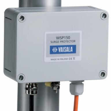
Figure 8 Surge Protector (optional)
The following surge protectors are available from Vaisala:
-Vaisala Surge Protector WSP150 is a compact transient overvoltage suppressor designed for outdoor use. It can be used with all Vaisala wind and weather instruments. The WSP150 should be installed close to the protected instrument (max 3 m).
-Vaisala Surge Protector WSP152 is designed to be used with Vaisala WXT transmitters and WMT sensors, to protect the host PC against surges entering through the USB port. The WSP152 should be installed close to the PC, no further than the USB cable can reach (1.4 m).
Vaisala recommends using surge protectors when weather instruments are installed on top of high buildings or masts and in open grounds, that is, anywhere with an elevated risk of lightning strike. Also use the surge protectors if your cable length exceeds 30 m or you have unshielded, open-wire lines.
24 __________________________________________________________________ M210906EN-C
Chapter 3 ______________________________________________________ Functional Description
CHAPTER 3
FUNCTIONAL DESCRIPTION
This chapter describes the measurement principles and heating function of Weather Transmitter WXT520.
Wind Measurement Principle
WXT520 uses Vaisala WINDCAP® sensor technology in wind measurement.
The wind sensor has an array of three equally spaced ultrasonic transducers on a horizontal plane. Wind speed and wind directions are determined by measuring the time it takes the ultrasound to travel from each transducer to the other two.
The wind sensor measures the transit time (in both directions) along the three paths established by the array of transducers. This transit time depends on the wind speed along the ultrasonic path. For zero wind speed, both the forward and reverse transit times are the same. With wind along the sound path, the up-wind direction transit time increases and the down-wind transit time decreases.
VAISALA_______________________________________________________________________ 25
User’s Guide ______________________________________________________________________
The wind speed is calculated from the measured transit times using the following formula:
Vw |
= 0.5 L 1 tf – 1 tr |
where |
|
Vw |
= Wind speed |
L |
= Distance between the two transducers |
tf |
= Transit time in forward direction |
tr |
= Transit time in reverse direction |
Measuring the six transit times allows Vw to be computed for each of
the three ultrasonic paths. The computed wind speeds are independent of altitude, temperature and humidity, which are cancelled out when the transit times are measured in both directions, although the individual transit times depend on these parameters.
Using Vw values of two array paths is enough to compute wind speed
and wind direction. A signal processing technique is used so that wind speed and wind direction are calculated from the two array paths of best quality.
The wind speed is represented as a scalar speed in selected units (m/s, kt, mph, km/h). The wind direction is expressed in degrees (°). The wind direction reported by WXT520 indicates the direction that the wind comes from. North is represented as 0°, east as 90°, south as 180°, and west as 270°.
The wind direction is not calculated when the wind speed drops below 0.05 m/s. In this case, the last calculated direction output remains until the wind speed increases again to the level of 0.05 m/s.
The average values of wind speed and direction are calculated as a scalar average of all samples over the selected averaging time
(1 ... 3600 s) with a selectable updating interval. The sample count depends on the selected sampling rate: 4 Hz (default), 2 Hz or 1 Hz. The minimum and maximum values of wind speed and direction represent the corresponding extremes during the selected averaging time. See also Appendix D, Wind Measurement Averaging Method, on page 163.
26 __________________________________________________________________ M210906EN-C
Chapter 3 ______________________________________________________ Functional Description
Depending on user selection the wind speed extreme values can be computed in two alternative ways; either with the traditional minimum/ maximum calculation or with the 3-second gust & lull calculation recommended by the WMO (World Meteorological Organization). In the latter case the highest and lowest 3-second average values (updated once a second) replace the maximum and minimum values in reporting of wind speed, while the wind direction variance is returned in the traditional way.
The WXT520 constantly monitors the wind measurement signal quality. If poor quality is detected, the wind values are marked as invalid. If over half of the measurement values can be considered as invalid, the last valid wind values are returned as missing data. However, in the SDI-12 protocol the invalid values will be marked as zeroes.
Precipitation Measurement Principle
WXT520 uses Vaisala RAINCAP® Sensor 2-technology in precipitation measurement.
The precipitation sensor comprises of a steel cover and a piezoelectrical sensor mounted on the bottom surface of the cover.
The precipitation sensor detects the impact of individual raindrops. The signals from the impact are proportional to the volume of the drops. Hence, the signal of each drop can be converted directly to accumulated rainfall. Advanced noise filtering technique is used to filter out signals originating from other sources than raindrops.
The measured parameters are accumulated rainfall, rain current and peak intensity, and the duration of a rain event. Detection of each individual drop enables computing of rain amount and intensity with high resolution. Precipitation current intensity internally updated every 10 seconds represents the intensity during the one minute period before requesting/automatic precipitation message sending (for fast reacting to a rain event, during the first minute of the rain event the intensity is calculated over the period rain has lasted in 10-second steps instead of fixed one minute). Precipitation peak intensity represents the maximum of the calculated current intensity values since last precipitation intensity reset.
VAISALA_______________________________________________________________________ 27
User’s Guide ______________________________________________________________________
The sensor is also capable of distinguishing hails from raindrops. The measured hail parameters are cumulative amount of hails, current and peak hail intensity and the duration of a hail shower.
The precipitation sensor operates in the following four modes:
-Precipitation Start/End mode:
Transmitter sends automatically a precipitation message 10 seconds after the recognition of the first drop. The messages are sent continuously as the precipitation proceeds and stopped when the precipitation ends.
-Tipping bucket mode:
This mode emulates tipping bucket type precipitation sensors. Transmitter sends automatically a precipitation message when the counter detects one unit increment (0.1 mm/0.01 in).
-Time mode:
Transmitter sends automatically a precipitation message in the update intervals defined by the user.
-Polled mode:
Transmitter sends a precipitation message whenever requested by the user.
More information about the precipitation sensor operation modes can be found in section Precipitation Sensor on page 117.
28 __________________________________________________________________ M210906EN-C
Loading...