


 Loading...
USER'S GUIDE
Vaisala HUMICAP® Humidity and
Temperature Probes
HMP45A/D
U274EN-1.2
PUBLISHED BY |
|
|
|
Vaisala Oyj |
Phone (int.): |
+358 |
9 8949 1 |
P.O. Box 26 |
Fax: |
+358 |
9 8949 2227 |
FIN-00421 Helsinki |
|
|
|
Finland |
|
|
|
Visit our Internet pages at http://www.vaisala.com/
© Vaisala 2006
No part of this manual may be reproduced in any form or by any means, electronic or mechanical (including photocopying), nor may its contents be communicated to a third party without prior written permission of the copyright holder.
The contents are subject to change without prior notice.
Please observe that this manual does not create any legally binding obligations for Vaisala towards the customer or end user. All legally binding commitments and agreements are included exclusively in the applicable supply contract or Conditions of Sale.
|
HMP45A and HMP45D |
U274en-1.2 |
Operating Manual |
1.GENERAL
The HMP45A and HMP45D probes are designed for the measurement of relative humidity and temperature. Humidity measurement is based on the capacitive thin film polymer sensor HUMICAP 180. Temperature measurement is based on resistive platinum sensors (Pt 100 and Pt 1000). Both the humidity and temperature sensors are located at the tip of the probe and in standard version protected by a membrane filter. The HMP45A and HMP45D have a similar humidity output, but the temperature output is active in HMP45A (voltage output 0-1V) and passive in HMP45D (resistive output Pt 100).
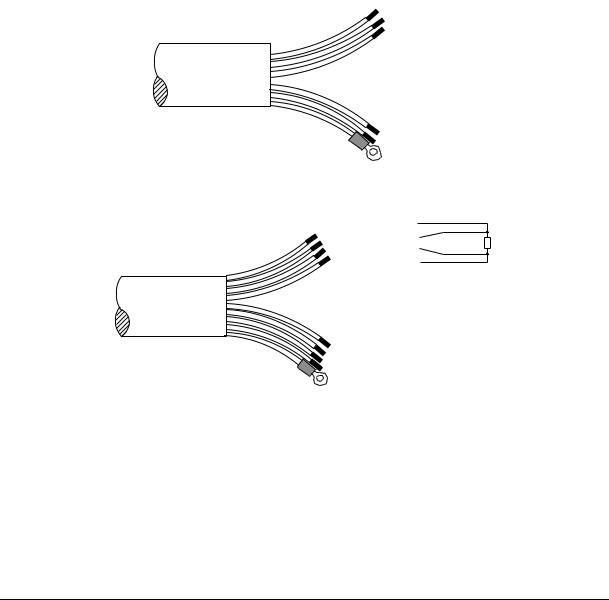
2.CONNECTIONS
The cable wires are connected as shown in Figure 1.
Y E L O U T P U T
0...1V=-40...+60 ˚C
B LU V + 7...35VDC
B R N O U T PU T
0...1V=0...100%RH
H M P 4 5 A |
V I O G N D |
|
RE D GN D (S E NSE )
GR E Y ( SHIE LD )
YEL |
Pt100 |
|
|
WHT |
Pt100 |
Pt100 |
|
GRN |
Pt100 |
||
|
|||
BLK |
Pt100 |
|
HMP45D |
BLU 7...35VDC |
|
BRN OUTPUT 0...1V=0...100%RH |
||
|
||
|
VIO GND |
|
|
RED GND (SENSE) |
|
|
GREY (SHIELD) |
|
|
Figure 1 Wire colours |
SIGNAL GROUND is used for output signal in a differential measurement. With SIGNAL GROUND, the cable can be extended up to 100 metres without disturbing the measurement accuracy. When outputs are not measured against
SIGNAL GROUND, connect GROUND and SIGNAL GROUND to the same point.
1
Loading...