


 Loading...
Vaisala TMP1, HMP9, MMP8, HMP8, HMP7 User Manual
...M212022EN-D
User Guide
Vaisala Indigo compatible humidity and temperature probes
HMP3, HMP4, HMP5, HMP7, HMP8, HMP9, MMP8, TMP1

PUBLISHED BY
Vaisala Oyj
Vanha Nurmijärventie 21, FI-01670 Vantaa, Finland P.O. Box 26, FI-00421 Helsinki, Finland
+358 9 8949 1
Visit our Internet pages at www.vaisala.com.
© Vaisala Oyj 2020
No part of this document may be reproduced, published or publicly displayed in any form or by any means, electronic or mechanical (including photocopying), nor may its contents be modified, translated, adapted, sold or disclosed to a third party without prior written permission of the copyright holder. Translated documents and translated portions of multilingual documents are based on the original English versions. In ambiguous cases, the English versions are applicable, not the translations.
The contents of this document are subject to change without prior notice.
Local rules and regulations may vary and they shall take precedence over the information contained in this document. Vaisala makes no representations on this document’s compliance with the local
rules and regulations applicable at any given time, and hereby disclaims any and all responsibilities related thereto.
This document does not create any legally binding obligations for Vaisala towards customers or end users. All legally binding obligations and agreements are included exclusively in the applicable supply contract or the General Conditions of Sale and General Conditions of Service of Vaisala.
This product contains software developed by Vaisala or third parties. Use of the software is governed by license terms and conditions included in the applicable supply contract or, in the absence of separate license terms and conditions, by the General License Conditions of Vaisala Group.
|
|
Table of contents |
Table of contents |
|
|
1. |
About this document..................................................................................... |
7 |
1.1 |
Version information.......................................................................................... |
7 |
1.2 |
Related manuals................................................................................................ |
7 |
1.3 |
Documentation conventions........................................................................... |
8 |
1.4 |
Trademarks........................................................................................................ |
8 |
2. |
Product overview............................................................................................ |
9 |
2.1 |
Probe structure................................................................................................. |
9 |
2.2 |
Basic features and options.............................................................................. |
9 |
2.3 |
Output parameters......................................................................................... |
10 |
2.4 |
Additional features with Indigo 200 series transmitters............................. |
11 |
2.5 |
Safety................................................................................................................. |
11 |
2.6 |
ESD protection................................................................................................. |
12 |
2.7 |
Regulatory compliances................................................................................. |
12 |
2.7.1 |
FCC Part 15 compliance statement......................................................... |
12 |
2.7.2 |
Canada ICES-003 compliance statement............................................. |
13 |
3. |
Installation........................................................................................................ |
14 |
3.1 |
HMP3 probe...................................................................................................... |
15 |
3.2 |
HMP4 probe..................................................................................................... |
16 |
3.3 |
HMP5 probe...................................................................................................... |
17 |
3.4 |
HMP7 probe...................................................................................................... |
18 |
3.5 |
HMP8 probe..................................................................................................... |
19 |
3.5.1 |
Attaching ball valve kit to process........................................................ |
20 |
3.6 |
HMP9 probe...................................................................................................... |
21 |
3.6.1 |
Installing HMP9 through a cable gland................................................. |
22 |
3.7 |
MMP8 probe.................................................................................................... |
23 |
3.8 |
TMP1 probe...................................................................................................... |
24 |
3.9 |
Wiring............................................................................................................... |
25 |
4. |
Configuration with Insight software..................................................... |
27 |
4.1 |
Vaisala Insight software................................................................................. |
27 |
4.2 |
Installing driver for the USB service cable................................................... |
27 |
4.3 |
Connecting to Insight software.................................................................... |
28 |
4.4 |
Configuration options.................................................................................... |
29 |
5. |
Using probe with Indigo transmitters................................................... |
31 |
5.1 |
Indigo 200 series transmitter overview........................................................ |
31 |
5.2 |
Attaching probe to Indigo 200 series transmitter..................................... |
33 |
5.3 |
Wireless configuration interface overview.................................................. |
34 |
5.4 |
Connecting to wireless configuration interface.......................................... |
34 |
5.5 |
Logging in to wireless configuration interface........................................... |
35 |
6. |
Maintenance.................................................................................................... |
36 |
6.1 |
Cleaning the probe......................................................................................... |
36 |
6.1.1 |
Chemical tolerance................................................................................. |
36 |
1
HMP3, HMP4, HMP5, HMP7, HMP8, HMP9, MMP8, TMP1 User Guide |
M212022EN-D |
6.2 |
|
Changing the probe filter.............................................................................. |
37 |
6.3 |
|
Replacing the HUMICAPâ R2 sensor........................................................... |
37 |
6.4 |
|
Calibration and adjustment........................................................................... |
39 |
6.4.1 |
|
Adjustment points and requirements.................................................. |
40 |
6.4.2 |
|
Adjusting measurement with Insight software.................................... |
41 |
6.4.3 |
|
Adjusting measurement with Indigo 200 transmitter........................ |
42 |
7. |
Troubleshooting............................................................................................ |
46 |
|
7.1 |
|
Problem situations......................................................................................... |
46 |
7.2 |
|
Error messages............................................................................................... |
46 |
8. |
Technical data................................................................................................ |
49 |
|
8.1 |
|
HMP3 specifications....................................................................................... |
49 |
8.2 |
|
HMP4 specifications....................................................................................... |
52 |
8.3 |
|
HMP5 specifications....................................................................................... |
55 |
8.4 |
|
HMP7 specifications....................................................................................... |
58 |
8.5 |
|
HMP8 specifications........................................................................................ |
61 |
8.6 |
|
HMP9 specifications....................................................................................... |
64 |
8.7 |
|
MMP8 specifications....................................................................................... |
67 |
8.8 |
|
TMP1 specifications........................................................................................ |
70 |
8.9 |
|
Accessories and spare parts.......................................................................... |
72 |
Appendix A: Modbus reference................................................................... |
77 |
||
A.1 |
|
Default communication settings................................................................... |
77 |
A.2 |
|
Function codes................................................................................................ |
77 |
A.3 |
|
Data encoding................................................................................................. |
77 |
A.3.1 |
|
32-bit floating point or integer format................................................. |
78 |
A.3.2 |
16-bit integer format............................................................................... |
78 |
|
A.4 |
|
Modbus registers............................................................................................ |
78 |
A.4.1 |
|
Measurement Data Registers................................................................. |
79 |
A.4.2 |
Configuration registers........................................................................... |
82 |
|
A.4.3 |
Device identification objects................................................................. |
85 |
|
A.4.4 |
Status registers........................................................................................ |
85 |
|
A.4.5 |
Test value registers.................................................................................. |
87 |
|
A.4.6 |
Modbus communication examples....................................................... |
88 |
|
Online store....................................................................................................... |
91 |
||
Warranty............................................................................................................. |
91 |
||
Technical support............................................................................................. |
91 |
||
Recycling............................................................................................................ |
91 |
||
2
List of figures
List of figures
Figure |
1 |
Probe parts......................................................................................................... |
9 |
Figure |
2 |
Example installation........................................................................................ |
14 |
Figure |
3 |
HMP3 probe dimensions................................................................................ |
15 |
Figure |
4 |
HMP4 probe dimensions................................................................................ |
16 |
Figure |
5 |
HMP5 probe dimensions................................................................................ |
17 |
Figure |
6 |
Optional mounting flange 210696 dimensions....................................... |
17 |
Figure |
7 |
HMP7 probe dimensions................................................................................ |
18 |
Figure |
8 |
HMP8 probe dimensions................................................................................ |
19 |
Figure |
9 |
HMP9 probe dimensions................................................................................ |
21 |
Figure 10 |
Installing HMP9 probe head through a cable gland.............................. |
22 |
|
Figure |
11 |
MMP8 dimensions........................................................................................... |
23 |
Figure |
12 |
TMP1 probe dimensions................................................................................ |
24 |
Figure |
13 |
M12 5-pin A-coded male connector pinout............................................. |
25 |
Figure |
14 |
RS-485 wiring.................................................................................................. |
25 |
Figure |
15 |
Connecting probe to Insight........................................................................ |
29 |
Figure |
16 |
HMP5 in Insight software.............................................................................. |
30 |
Figure |
17 |
HMP7 attached to Indigo 200 series transmitter.................................... |
31 |
Figure |
18 |
HMP7 attached to Indigo 200 series transmitter with a cable........... |
32 |
Figure |
19 |
Attaching the probe to Indigo 200 series transmitter......................... |
33 |
Figure 20 |
Enabling and accessing wireless configuration interface |
|
|
|
|
of Indigo 200................................................................................................... |
34 |
Figure |
21 |
Indigo login view............................................................................................. |
35 |
Figure 22 |
HMP3 probe head with filter removed...................................................... |
38 |
|
Figure 23 |
Calibration page in the Indigo 200 wireless |
|
|
|
|
configuration interface.................................................................................. |
44 |
Figure 24 |
HMP3 humidity measurement accuracy as a function of |
|
|
|
|
temperature..................................................................................................... |
50 |
Figure 25 |
HMP3 temperature measurement accuracy over full range............... |
50 |
|
Figure 26 |
HMP3 probe dimensions............................................................................... |
52 |
|
Figure 27 |
HMP4 humidity measurement accuracy as a function of |
|
|
|
|
temperature...................................................................................................... |
53 |
Figure 28 |
HMP4 temperature measurement accuracy over full range............... |
53 |
|
Figure 29 |
HMP4 probe dimensions............................................................................... |
55 |
|
Figure 30 |
HMP5 humidity measurement accuracy as a function of |
|
|
|
|
temperature..................................................................................................... |
56 |
Figure |
31 |
HMP5 temperature measurement accuracy over full range............... |
56 |
Figure 32 |
HMP5 probe dimensions............................................................................... |
58 |
|
Figure 33 |
HMP7 humidity measurement accuracy as function of |
|
|
|
|
temperature...................................................................................................... |
59 |
Figure 34 |
HMP7 temperature measurement accuracy over full range............... |
59 |
|
Figure 35 |
HMP7 probe dimensions................................................................................ |
61 |
|
Figure 36 |
HMP8 humidity measurement accuracy as a function of |
|
|
|
|
temperature...................................................................................................... |
62 |
Figure 37 |
HMP8 temperature measurement accuracy over full range............... |
62 |
|
Figure 38 |
HMP8 probe dimensions.............................................................................. |
64 |
|
3
HMP3, HMP4, HMP5, HMP7, HMP8, HMP9, MMP8, TMP1 User Guide |
M212022EN-D |
|
Figure 39 |
Optional ball valve installation kit dimensions....................................... |
64 |
Figure 40 |
HMP9 probe dimensions............................................................................... |
67 |
Figure 41 |
Aw measurement accuracy.......................................................................... |
68 |
Figure 42 |
MMP8 dimensions........................................................................................... |
69 |
Figure 43 |
TMP1 temperature measurement accuracy over full range................. |
70 |
Figure 44 |
TMP1 probe dimensions................................................................................. |
71 |
Figure 45 |
Optional duct kit 215003 dimensions........................................................ |
72 |
4
List of tables
List of tables
Table |
1 |
Document versions (English)........................................................................... |
7 |
Table |
2 |
Related Manuals................................................................................................... |
7 |
Table |
3 |
Availability of output parameters................................................................. |
10 |
Table |
4 |
Suitability of cleaning agents........................................................................ |
36 |
Table |
5 |
Troubleshooting table..................................................................................... |
46 |
Table |
6 |
Measurement performance............................................................................ |
49 |
Table |
7 |
Operating environment.................................................................................. |
50 |
Table |
8 |
Inputs and outputs............................................................................................ |
51 |
Table |
9 |
Mechanical specifications................................................................................ |
51 |
Table 10 |
Measurement performance............................................................................ |
52 |
|
Table |
11 |
Operating environment................................................................................... |
54 |
Table |
12 |
Inputs and outputs........................................................................................... |
54 |
Table |
13 |
Mechanical specifications............................................................................... |
54 |
Table 14 |
Measurement performance............................................................................ |
55 |
|
Table |
15 |
Operating environment................................................................................... |
57 |
Table |
16 |
Inputs and outputs............................................................................................ |
57 |
Table |
17 |
Mechanical specifications............................................................................... |
57 |
Table |
18 |
Measurement performance............................................................................ |
58 |
Table |
19 |
Operating environment.................................................................................. |
60 |
Table 20 |
Inputs and outputs........................................................................................... |
60 |
|
Table |
21 |
Mechanical specifications.............................................................................. |
60 |
Table 22 |
Measurement performance............................................................................. |
61 |
|
Table 23 |
Operating environment................................................................................... |
63 |
|
Table 24 |
Inputs and outputs........................................................................................... |
63 |
|
Table 25 |
Mechanical specifications............................................................................... |
63 |
|
Table 26 |
Measurement performance........................................................................... |
64 |
|
Table 27 |
Operating environment................................................................................... |
65 |
|
Table 28 |
Inputs and outputs........................................................................................... |
66 |
|
Table 29 |
Mechanical specifications............................................................................... |
66 |
|
Table 30 |
Measurement performance............................................................................ |
67 |
|
Table |
31 |
Operating environment................................................................................... |
68 |
Table 32 |
Inputs and outputs........................................................................................... |
68 |
|
Table 33 |
Mechanical Specifications.............................................................................. |
69 |
|
Table 34 |
Measurement performance............................................................................ |
70 |
|
Table 35 |
Operating environment................................................................................... |
70 |
|
Table 36 |
Inputs and outputs............................................................................................ |
71 |
|
Table 37 |
Mechanical specifications................................................................................ |
71 |
|
Table 38 |
Connection cables............................................................................................. |
72 |
|
Table 39 |
Accessories......................................................................................................... |
73 |
|
Table 40 |
Spare parts.......................................................................................................... |
73 |
|
Table |
41 |
Spare parts.......................................................................................................... |
73 |
Table 42 |
Accessories......................................................................................................... |
73 |
|
Table 43 |
Spare parts.......................................................................................................... |
74 |
|
Table 44 |
Accessories......................................................................................................... |
74 |
|
Table 45 |
Spare parts.......................................................................................................... |
74 |
|
5
HMP3, HMP4, HMP5, HMP7, HMP8, HMP9, MMP8, TMP1 User Guide |
M212022EN-D |
|
Table 46 |
Accessories......................................................................................................... |
74 |
Table 47 |
Spare parts.......................................................................................................... |
75 |
Table 48 |
Accessories......................................................................................................... |
75 |
Table 49 |
Accessories......................................................................................................... |
75 |
Table 50 |
Spare parts.......................................................................................................... |
75 |
Table 51 |
Accessories......................................................................................................... |
75 |
Table 52 |
Default Modbus serial communication settings....................................... |
77 |
Table 53 |
Modbus function codes................................................................................... |
77 |
Table 54 |
16-bit signed integer format details............................................................. |
78 |
Table 55 |
Floating point measurement data registers (read-only)....................... |
79 |
Table 56 |
Integer measurement data registers (read-only).................................... |
80 |
Table 57 |
Modbus configuration data registers (writable)...................................... |
82 |
Table 58 |
Device identification objects......................................................................... |
85 |
Table 59 |
Modbus status data registers (read-only)................................................. |
85 |
Table 60 |
Error codes in register 0203hex..................................................................... |
86 |
Table 61 |
Modbus test registers (read-only)............................................................... |
87 |
6
Chapter 1 – About this document
1. About this document
1.1 Version information
This document provides instructions for installing, using, and maintaining Vaisala HUMICAPâ Humidity and Temperature Probes HMP3, HMP4, HMP5, HMP7, HMP8, HMP9, Moisture in Oil Probe MMP8, and Temperature Probe TMP1.
Table 1 Document versions (English)
Document code |
Date |
Description |
|
|
|
|
|
M212022EN-D |
March 2020 |
Added content for HMP3 and MMP8 probe models. |
|
|
|
|
|
M212022EN-C |
June 2019 |
Applicable from software version 1.0.9 onward. Added |
|
|
|
content for HMP9 probe model. Other added content: |
|
|
|
• Output parameters (page 10) |
|
|
|
• |
Adjusting measurement with Indigo 200 transmitter |
|
|
|
(page 42) |
|
|
• |
Problem situations (page 46) |
|
|
• Error messages (page 46) |
|
|
|
• |
Status registers (page 85) |
|
|
Updated content: |
|
|
|
• |
Updated technical specifications and dimension |
|
|
|
drawings of probe models |
|
|
• Updated presentation of Modbus register maps |
|
|
|
• |
Corrected numbering of decimal registers in section |
|
|
|
Measurement Data Registers (page 79) |
|
|
|
|
M212022EN-B |
June 2018 |
Applicable from software version 1.0.6 onward. Updated |
|
|
|
instructions for connecting to Indigo transmitters. |
|
|
|
Updated sections Measurement Data Registers (page 79) |
|
|
|
and Configuration registers (page 82). |
|
|
|
|
|
1.2 Related manuals
Table 2 Related Manuals
Document code |
Name |
|
|
|
|
M211982EN |
HMP3, HMP4, HMP5, HMP7, HMP8, HMP9, MMP8, and TMP1 Quick Guide |
|
|
|
7
HMP3, HMP4, HMP5, HMP7, HMP8, HMP9, MMP8, TMP1 User Guide |
M212022EN-D |
1.3 Documentation conventions
WARNING! Warning alerts you to a serious hazard. If you do not read and follow instructions carefully at this point, there is a risk of injury or even death.
CAUTION! Caution warns you of a potential hazard. If you do not read and follow instructions carefully at this point, the product could be damaged or important data could be lost.
Note highlights important information on using the product.
Tip gives information for using the product more efficiently.
Lists tools needed to perform the task.
Indicates that you need to take some notes during the task.
1.4 Trademarks
Vaisalaâ and HUMICAPâ are registered trademarks of Vaisala Oyj.
All other product or company names that may be mentioned in this publication are trade names, trademarks, or registered trademarks of their respective owners.
8
Chapter 2 – Product overview
2. Product overview
HMP series probes are humidity and temperature measurement probes with a digital output (Modbus protocol). The probes are designed for demanding humidity and temperature measurement applications. The probes have a two-part structure, with measurement electronics contained in the probe body and sensor(s) in the probe head. The probe body and the probe head are connected by a cable. Length options for this connecting cable depend on the probe model.
The probes are compatible with Vaisala Indigo transmitters. They can also be connected to Vaisala Insight software for configuration, calibration, adjustment, diagnostics, and temporary online monitoring.
2.1 Probe structure |
|
|
|
|
1 |
Figure 1 Probe parts |
|||
|
|
|
||
|
1 |
Protection cap (remove before use) |
||
2 |
2 |
5-pin M12 connector |
||
3 |
Probe body with type label |
|||
|
||||
|
4 |
Status indicator: |
||
6 |
|
Green |
Power on and probe online, |
|
3 |
|
|||
|
|
flashes when communicating |
||
|
|
|
||
|
|
Red |
Error |
|
|
|
Off |
Power off or indicator |
|
|
|
|
disabled |
|
7 |
5 |
Probe cable (do not cut) |
||
|
6 |
Probe head (HMP7 model shown) |
||
4 |
7 |
Location of sensor(s) on the probe |
||
|
|
head. Most probe models have a |
||
|
|
removable filter over the sensors that |
||
8 |
|
can be replaced if it gets dirty or |
||
|
damaged. Note that HMP9 and TMP1 |
|||
5 |
|
do not have a removable filter. |
||
8 |
Protection cap (remove before use) |
|||
|
||||
2.2 Basic features and options
•Comprehensive list of output parameters. For example: relative humidity, temperature, dew point temperature, wet-bulb temperature, absolute humidity, mixing ratio, water vapor pressure, enthalpy. See Output parameters (page 10).
•Sensor purge provides superior chemical resistance (HMP models only)
•Probe and sensor warming functions minimize condensation on probe (HMP models only)
9

HMP3, HMP4, HMP5, HMP7, HMP8, HMP9, MMP8, TMP1 User Guide |
M212022EN-D |
•Traceable calibration certificate:
•HMP and MMP models: 6 points for humidity, 1 point for temperature
•TMP1: 2 points for temperature
•Standalone Modbus RTU over RS-485
•Compatible with Indigo series of transmitters
•Can be connected to Vaisala Insight PC software for configuration, calibration, diagnostics, and temporary online monitoring
2.3 Output parameters
On HMP probe models, the values of all available output parameters are always locked when chemical purge or extra heat functions are heating the sensor.
Output parameter is available
Output parameter is available but its value is locked during sensor warming or probe heating (HMP7 only) unless temperature is written to register 0334hex from an external
source
Output parameter is not available on this model
Table 3 Availability of output parameters
Output parameter |
Output unit |
HMP3, 4, 5, |
MMP8 |
TMP1 |
|
|
7, 8, and 9 |
|
|
|
|
|
|
|
Relative humidity |
%RH |
|
|
|
|
|
|
|
|
Temperature |
°C |
|
|
|
|
|
|
|
|
Dew point temperature |
°C |
|
|
|
|
|
|
|
|
Dew/frost point temperature |
°C |
|
|
|
|
|
|
|
|
Dew/frost point temperature at 1 atm |
°C |
|
|
|
|
|
|
|
|
Dew point temperature at 1 atm |
°C |
|
|
|
|
|
|
|
|
Absolute humidity |
g/m3 |
|
|
|
Mixing ratio |
g/kg |
|
|
|
|
|
|
|
|
Wet-bulb temperature |
°C |
|
|
|
|
|
|
|
|
Water concentration |
ppmv |
|
|
|
Water vapor pressure |
hPa |
|
|
|
|
|
|
|
|
Water vapor saturation pressure |
hPa |
|
|
|
|
|
|
|
|
Enthalpy |
kJ/kg |
|
|
|
|
|
|
|
|
Water activity |
- |
|
|
|
|
|
|
|
|
10
Chapter 2 – Product overview
Output parameter |
Output unit |
HMP3, 4, 5, |
MMP8 |
TMP1 |
|
|
7, 8, and 9 |
|
|
|
|
|
|
|
Dew point temperature difference |
°C |
|
|
|
|
|
|
|
|
Absolute humidity at NTP |
g/m3 |
|
|
|
Water concentration in oil |
ppmv |
|
|
|
Relative saturation |
%RS |
|
|
|
|
|
|
|
|
Water mass fraction |
ppmw |
|
|
|
2.4 Additional features with Indigo 200 series transmitters
Connecting the probe to an Indigo transmitter provides a range of additional options for outputs, measurement viewing, status monitoring, and configuration interface access.
Examples of additional features available with Indigo 200 series transmitters include:
•3.5” TFT LCD color display or non-display model with LED indicator
•Digital output or 3 analog outputs (depending on the transmitter model)
•2 configurable relays
•Wireless browser-based configuration interface for mobile devices and computers (IEEE 802.11 b/g/n WLAN)
The selection of available additional features (for example, output and connectivity options) varies depending on the Indigo transmitter model. For more information on Indigo transmitters, see www.vaisala.com/indigo.
2.5 Safety
WARNING! When returning a product for calibration or repair, make sure it has not been exposed to dangerous contamination, and is safe to handle without special precautions.
CAUTION! Do not attempt to open the probe body. There are no user serviceable parts inside the probe body.
CAUTION! Do not touch the probe head with your bare hands. Touching will deposit impurities on the probe head.
11

HMP3, HMP4, HMP5, HMP7, HMP8, HMP9, MMP8, TMP1 User Guide |
M212022EN-D |
CAUTION! Be aware that the probe head may become hot to touch when functions such as chemical purge and probe heating are active.
2.6 ESD protection
Electrostatic discharge (ESD) can cause immediate or latent damage to electronic circuits. Vaisala products are adequately protected against ESD for their intended use. However, it is possible to damage the product by delivering an electrostatic discharge when touching, removing or inserting any objects inside the equipment housing.
Avoid touching component contacts or connectors when working with the device.
2.7 Regulatory compliances
The probes are in conformity with the provisions of the following EU directives:
•RoHS Directive
•EMC Directive
Conformity is shown by compliance with the following standards:
•EN 50581: Technical documentation for the assessment of electrical and electronic products with respect to the restriction of hazardous substances.
•EN 61326-1: Electrical equipment for measurement, control, and laboratory use – EMC requirements – intended for use in industrial locations.
•EN 55032: Information technology equipment – Radio disturbance characteristics – Limits and methods of measurement.
2.7.1 FCC Part 15 compliance statement
This equipment has been tested and found to comply with the limits for a Class B digital device, pursuant to Part 15 of the FCC rules. These limits are designed to provide reasonable protection against harmful interference in a residential installation. This equipment generates, uses and can radiate radio frequency energy and, if not installed and used in accordance with the instructions, may cause harmful interference to radio communications. However, there is no guarantee that the interference will not occur in a particular installation. If this equipment does cause harmful interference to radio or television reception, which can be determined by turning the equipment off and on, the user is encouraged to try to correct the interference by one or more of the following measures:
•Reorient or relocate the receiving antenna.
•Increase the separation between the equipment and receiver.
•Connect the equipment into an outlet on a circuit different from that of the receiver.
•Consult the dealer or an experienced radio/TV technician for help.
12

Chapter 2 – Product overview
CAUTION! Changes or modifications to this equipment not expressly approved by the party responsible for compliance could void the user's authority to operate the equipment.
2.7.2 Canada ICES-003 compliance statement
This Class B digital apparatus complies with Canadian ICES 003.
Cet appareil numerique de la classe B est conforme a la norme NMB 003 du Canada.
13

HMP3, HMP4, HMP5, HMP7, HMP8, HMP9, MMP8, TMP1 User Guide |
M212022EN-D |
3. Installation
When you choose the installation location for the probe, consider the following:
•Verify the operating environment specification of the probe model. The probe head typically has a much wider operating temperature range than the probe body.
•If the temperature of the measured environment differs greatly from ambient temperature, the entire probe head and preferably plenty of cable must be inside the measured environment. This prevents measurement inaccuracy caused by heat conduction along the cable.
•Probe mounting options are model-specific.
4 |
1 |
3 |
2 |
Figure 2 Example installation
1Mount the probe head horizontally to prevent any water condensing on the probe head from running to the sensors.
2Let the cable hang loosely to prevent condensed water from running along the cable to the probe body or probe head.
3Attach the probe body to a wall or other surface using the two mounting clips (Vaisala item 243257SP) supplied with the probe. Each clip attaches to the installation surface with one screw (screw hole Ø 4.2 mm).
4Cable to Modbus master or Indigo transmitter.
CAUTION! The supplied mounting clips are not designed to withstand strong vibration. Use other methods to secure the probe body if necessary. For example, attach the probe body using a cable tie.
More information
Default communication settings (page 77)
14
3.1 HMP3 probe
136 [5.35]
Chapter 3 – Installation
mm |
[in] |
M12/5
Ø 25 [0.98]
Probe cable 2 m [6.56 ft]
98.5 [3.88]
78.5 [3.09]
37.5 [1.48]
|
|
|
|
|
|
|
|
|
|
|
|
|
|
|
|
|
|
|
|
|
|
|
|
|
|
|
|
|
|
|
|
|
|
|
|
|
|
|
|
|
|
|
|
|
|
|
|
|
|
|
|
|
|
|
|
Ø 5 [0.2] |
M9x1 |
Ø 12 [0.47] |
|||||||||||
|
|
||||||||||||
Figure 3 HMP3 probe dimensions
Vaisala HUMICAPâ Humidity and Temperature Probe HMP3 is a general purpose probe designed for various industrial processes. The probe structure allows for replacing the sensor without tools, making it suitable for applications such as paint booths and other industrial applications where periodic recalibration alone is not sufficient for maintaining the probe performance. Other suitable applications include, for example, industrial HVAC systems, cleanrooms, and environmental chambers.
•Operating temperature for probe head −40 … +120 °C (−40 … +248 °F)
•Operating temperature for probe body −40 … +80 °C (−40 … +176 °F)
If purchased with a composite sensor instead of the field replaceable HUMICAPâ R2 sensor, HMP3 can use the chemical purge feature. In environments with high concentrations of chemicals and cleaning agents, the chemical purge option helps to maintain measurement accuracy between calibration intervals.
15
HMP3, HMP4, HMP5, HMP7, HMP8, HMP9, MMP8, TMP1 User Guide
3.2 HMP4 probe
136 [5.35]
M212022EN-D
mm |
[in] |
M12/5
Ø 25 [0.98]
Probe cable 2 m [6.56 ft]
183 [7.20]
120 [4.72]
Ø 12 [0.47]
41 [1.61]
Ø 5 [0.2]
|
|
|
|
Fitting body NPT1/2” or M22×1.5 |
32 mm 27 mm |
with sealing ring Ø22×27×1.5 Cu |
|||
|
|
|
|
|
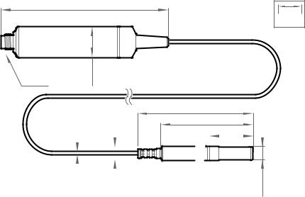
Figure 4 HMP4 probe dimensions
Vaisala HUMICAPâ Humidity and Temperature Probe HMP4 is designed for high-pressure applications such as compressed air systems in maritime, breathing air, and industrial applications, where measurement performance and chemical tolerance are essential.
•Temperature measurement range −70 … +180 °C (−94 … +356 °F)
•Operating pressure 0 … 10 MPa (0 … 100 bar)
•Operating temperature for probe body −40 … +80 °C (−40 … +176 °F)
•M22×1.5 or NPT1/2” fitting body
Use a sealing ring (Ø22×27×1.5 Cu) with the M22×1.5 fitting. Replace the sealing ring every time the probe is detached. Three sealing rings are supplied with the fitting.
16
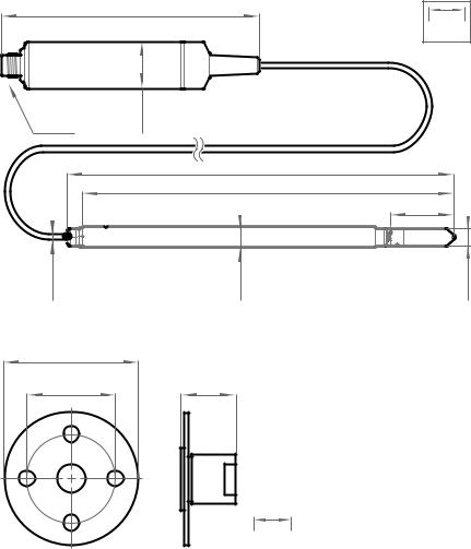
3.3 HMP5 probe
136 [5.35]
Chapter 3 – Installation
mm |
[in] |
M12/5 |
Ø 25 |
[0.98] |
|
|
Ø 5 [0.2]
Figure 5 HMP5 probe dimensions
75 [2.95]
50 [1.96]
Probe cable
2 m [6.56 ft] or 10 m [32.8 ft]
|
253 [9.96] |
|
243 [9.57] |
|
41 [1.61] |
Ø 13.5 [0.53] |
Ø 12 [0.47] |
19 [0.75]
mm [in]
Figure 6 Optional mounting flange 210696 dimensions
Vaisala HUMICAPâ Humidity and Temperature Probe HMP5 is designed for high-temperature applications such as baking ovens, pasta dryers, and industrial drying kilns, where measurement performance and chemical tolerance are essential.
• Temperature measurement range −70 … +180 °C (−94 … +356 °F)
17
HMP3, HMP4, HMP5, HMP7, HMP8, HMP9, MMP8, TMP1 User Guide |
M212022EN-D |
•Operating temperature of probe body −40 … +80 °C (−40 … +176 °F)
•250-mm (9.84 in) probe allows easy process installation through insulation
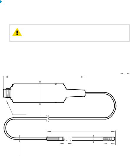
3.4 HMP7 probe
136 [5.35] |
mm |
|
|
|
[in] |
M12/5 |
Ø 25 |
[0.98] |
|
|
Ø 5 [0.2]
Figure 7 HMP7 probe dimensions
Probe cable
2 m [6.56 ft] or 10 m [32.8 ft]
99.5[3.92]
79.5[3.13]
37.5[1.48]
Ø12 [0.47] |
|
|
|
|
|
|
|
|
|
|
|
|
Groove for |
||||
|
|||||
|
|||||
|
|||||
|
|||||
|
lock ring |
||||
|
|
||||
|
|
|
|
|
|
Ø 12 [0.47]
Vaisala HUMICAPâ Humidity and Temperature Probe HMP7 is designed for applications that involve constant high humidity or rapid changes in humidity, such as drying and test chambers, combustion air, and other humidifiers and meteorological measurements, where measurement performance and chemical tolerance are essential.
•Temperature measurement range −70 … +180 °C (−94 … +356 °F)
•Operating temperature of probe body −40 … +80 °C (−40 … +176 °F)
•Probe heating and sensor warming functions minimize condensation on probe
•Vapor and pressure proof construction
Probe heating
HMP7 supports probe heating. Probe heating heats up not only the sensor, but the entire probe head. When probe temperature is heated above dew point temperature, condensation on the probe can be avoided while measuring the dew point temperature of the process.
18
Chapter 3 – Installation
If probe heating is enabled, output parameters that are dependent on temperature measurement (such as relative humidity) are locked whenever probe is heated unless the true temperature of the measured environment is updated to the temperature compensation register of the probe from another measurement instrument (for example, the TMP1 probe). Output parameters such as dew point temperature that can be measured or calculated without this external temperature information are available even without the temperature input.
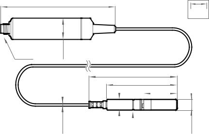
3.5 HMP8 probe
136 [5.35]
Ø5 |
[0.2] |
mm |
|
|
[in] |
M12/5 |
Ø 25 |
[0.98] |
|
|
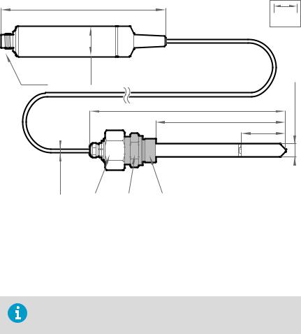
Figure 8 HMP8 probe dimensions
Probe cable 2 m [6.56 ft]
268 [10.55]
230 [9.06]
41 ... 185 [1.16 ... 7.28]
Fitting body
ISO1/2” or NPT1/2”
|
41 [1.61] |
Ø 13.5 [0.53] |
Ø 12 [0.47] |
Vaisala HUMICAPâ Humidity and Temperature Probe HMP8 is designed for pressurized applications in compressed air systems, refrigerant dryers, and other pressurized industrial applications, where easy insertion and removal of the probe and adjustable installation depth into the pipeline are needed.
•Temperature measurement range −70 … +180 °C (−94 … +356 °F)
•Operating temperature of probe body −40 … +80 °C (−40 … +176 °F)
•Operating pressure 0 … 4 MPa (0 … 40 bar)
•Probe installation depth can be freely adjusted and probe can be hot-swapped from pressurized pipelines with an installation valve
•ISO1/2" or NPT1/2" fitting body
19

HMP3, HMP4, HMP5, HMP7, HMP8, HMP9, MMP8, TMP1 User Guide |
M212022EN-D |
3.5.1 Attaching ball valve kit to process
1 |
G1/2
ISO 228/1
2 |
|
Ø14 |
3 |
|
4 |
Ø14 |
|
5 |
Ø14 |
Ø21.5 (drilling) |
1Ball valve handle: must point to the same direction as the ball valve body when installing.
2Extension nipple, threads G1/2 ISO228/1 and R1/2 ISO7/1.
3Ball valve body. When tightening the assembly, turn only from the ball valve body.
4Ball of the ball valve.
5Welding joint, threads R1/2 ISO7/1.
20
Chapter 3 – Installation
1. Attach the welding joint to the process pipe or chamber.
2.Apply a sealant (MEGA-PIPE EXTRA No. 7188 or LOCTITEâ No. 542 with activator No. 7649) on the threads of the welding joint and screw the bottom of the ball valve onto the welding joint.
3.Tighten the ball valve assembly by turning from the ball valve body.
CAUTION! Tightening the ball valve kit by turning the extension nipple can break the sealing. Tighten the ball valve assembly only from the ball valve body.
4.If you need to cap the ball valve assembly before installing or after removing the probe, attach a blanking nut to close the top of the valve.
3.6 HMP9 probe
M12/5
Ø 25 [0.98]
112 [4.41] |
|
|
|
|
||
|
|
|||||
mm |
||||||
|
|
|
|
|
|
[in] |
|
|
|
|
|
|
|
|
|
|
|
|
|
|
|
|
|
|
|
|
|
|
|
|
|
|
|
|
|
|
|
|
|
|
|
|
|
|
|
|
|
|
|
|
|
|
|
|
|
Probe cable 2 m [6.56 ft]
94 [3.70]
Ø 2.4 [0.094]
Figure 9 HMP9 probe dimensions
|
|
|
|
|
|
|
|
|
|
|
|
|
|
|
|
|
|
|
|
|
|
|
|
|
|
|
|
|
|
|
|
|
|
|
|
|
|
|
|
Attachment point |
16 [0.63] |
||||||||
Ø 5 ±0.05 |
|
|
|
|
|||||
[0.20 ±0.002] |
|
|
|
|
|||||
|
|
|
|
|
|
|
|
|
|
Vaisala HUMICAPâ Humidity and Temperature Probe HMP9 is designed for easy installation into rapidly changing environments where fast response time, measurement performance, and chemical tolerance are essential.
21
HMP3, HMP4, HMP5, HMP7, HMP8, HMP9, MMP8, TMP1 User Guide |
M212022EN-D |
The probe head can be mounted through thin metal walls using the included cable gland or mounting grommet. Two grommets are included: small one for 6.5 mm diameter hole, and large one for 12.5 mm diameter hole.
You can also attach the probe head directly using a zip tie. The probe head should be attached from the point near the black plastic part.
•Temperature measurement range −40 … +120 °C (−40 … +248 °F)
•Operating temperature of probe body −40 … +60 °C (−40 … +140 °F)
•Integrated filter (non-replaceable)
CAUTION! Do not damage the probe head by bending, crushing, or striking it. Avoid overtightening when installing the probe head through a cable gland.
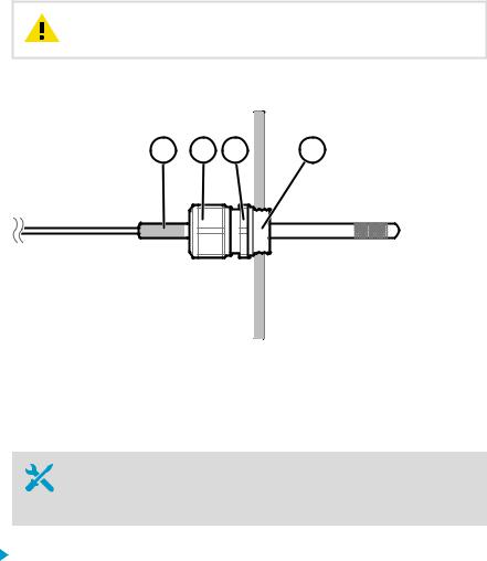
3.6.1 Installing HMP9 through a cable gland
1 |
2 |
3 |
4 |
Figure 10 Installing HMP9 probe head through a cable gland
1Black plastic part of the HMP9 probe head
2Nut for tightening the probe in place
3Base of the cable gland
4M10×1.5 threads of the cable gland
•M10×1.5 cable gland (included with HMP9 probe)
•Drill with 8.5 mm bit
•M10×1.5 threading tap
•13 mm wrench
1. Drill a 8.5 mm diameter hole in the installation location.
22

Chapter 3 – Installation
2.Use a threading tap to create a M10×1.5 thread in the hole.
3.Install the base of the cable gland in the hole and tighten with a 13 mm wrench.
4.Insert the seal of the cable gland in the base and place the nut of the cable gland over the probe head.
5.Insert the probe head in the cable gland up to the black plastic part of the probe head. Leave the black plastic part entirely outside the cable gland. Tighten the cable gland to finger tightness.
6.Tighten the nut of the cable gland with a 13 mm wrench until the probe head stops moving. Do not overtighten.
3.7 MMP8 probe
136 [5.35]
Ø5 |
[0.2] |
mm |
|
|
[in] |
M12/5 |
Ø 25 |
[0.98] |
|
|
Figure 11 MMP8 dimensions
Probe cable 2 m [6.56 ft]
262[10.32] 224 [8.82]
35 ... 179 [1.37 ... 7.05]
Fitting body
ISO1/2” or NPT1/2”
|
35 [1.37] |
Ø 13.5 [0.53] |
Ø 12 [0.47] |
Vaisala HUMICAPâ Moisture in Oil Probe MMP8 enables fast and reliable measurement of moisture in oil. It uses proven Vaisala HUMICAPâ sensor that was developed for demanding dissolved moisture measurements in transformer and lubrication oils, hydraulic fluids, and other liquids.
MMP8 measures dissolved moisture in oil in terms of the water activity (aw), relative saturation
(%RS), and temperature (T). Water activity or relative saturation indicate directly whether there is a risk of free water formation. This data is relevant in lubrication oil applications where detecting water ingress and preventing free water formation is crucial. The measurement is independent of oil type and age.
23

HMP3, HMP4, HMP5, HMP7, HMP8, HMP9, MMP8, TMP1 User Guide |
M212022EN-D |
MMP8 can also output ppm, the average mass concentration of water in oil. Vaisala has this conversion readily available for specific oils, including mineral transformer oil. This allows continuous measurement of ppm concentration in power transformer condition monitoring.
• Temperature measurement range −40 … +180 °C (−40 … +356 °F)
When installed with the ball valve kit, the MMP8 is ideal for installation into processes where the probe needs to be installed or removed while the process is running. Probe installation depth is adjustable. Pressure fitting options are ISO 1/2" and NPT 1/2". MMP8 is delivered with a manual pressing handle that allows the probe to be pushed against process pressure.
For installation instructions of the ball valve see Attaching ball valve kit to process (page 20).
3.8 TMP1 probe
136 [5.35]
mm [in]
M12/5
Ø 25 [0.98]
Probe cable
2 m [6.56 ft] or 10 m [32.8 ft]
130 [5.12]
Ø 3.2 [0.13] |
Ø 6 [0.24] |
Figure 12 TMP1 probe dimensions
Vaisala Temperature Probe TMP1 is designed for demanding temperature measurements in industrial applications such as pharmaceutical industry and calibration laboratories, where accuracy and robustness are essential.
•Temperature measurement range −70 … +180 °C (−94 … +356 °F)
•Operating temperature of probe body −40 … +80 °C (−40 … +176 °F)
24
Chapter 3 – Installation
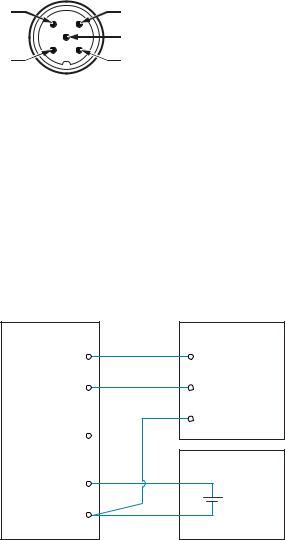
3.9 Wiring
4 |
3 |
|
5 |
1 |
2 |
Figure 13 M12 5-pin A-coded male connector pinout
Pin # |
Function |
Notes |
Wire colors in Vaisala cables |
|
|
|
|
1 |
Power supply |
Operating voltage: |
Brown |
|
|
• HMP7: 18 ... 30 VDC |
|
|
|
• Other models: 15 ... 30 VDC |
|
|
|
Current consumption: 10 mA typical, |
|
|
|
500 mA max. |
|
|
|
|
|
2 |
RS-485 - |
|
White |
|
|
|
|
3 |
Power GND and |
|
Blue |
|
RS-485 common |
|
|
|
|
|
|
4 |
RS-485 + |
|
Black |
|
|
|
|
5 |
Not connected |
|
Gray |
|
|
|
|
Probe |
RS-485 host |
Pin #4 |
RS-485 + |
RS-485 + |
|
Pin #2 |
RS-485 - |
RS-485 - |
|
|
RS-485 common |
Pin #5 |
|
|
DC power supply |
Pin #1 |
+ |
|
|
Power supply |
|
Pin #3 |
- |
|
|
Power GND |
|
RS-485 common |
|
Figure 14 RS-485 wiring |
|
25

HMP3, HMP4, HMP5, HMP7, HMP8, HMP9, MMP8, TMP1 User Guide |
M212022EN-D |
Recommended maximum length of the RS-485 line is 30 m (98 ft).
26

Chapter 4 – Configuration with Insight software
4. Configuration with Insight software
4.1 Vaisala Insight software
Vaisala Insight software is a configuration software for Indigo-compatible devices. With the Insight software, you can:
•See probe information and status
•See real-time measurement
•Record data up to 48 hours and export in CSV format
•Calibrate and adjust the probe
•Configure probe features such as measurement filtering, chemical purge, heating, and serial communication
Microsoft Windowsâ operating system and Vaisala USB cable (no. 242659) required.
Download Vaisala Insight software at www.vaisala.com/insight.
4.2 Installing driver for the USB service cable
Only Windowsâ operating systems are supported by the driver of the USB service cable.
1. Connect the USB service cable to a USB port on your computer. Windowsâ detects the new device and installs the appropriate driver.
2.Open Devices and Printers from the Windowsâ Start menu. Use search to find it if necessary (search for "devices").
27
Loading...