


 Loading...
USER'S GUIDE
Vaisala DRYCAP® Dewpoint Transmitters
DMT345 and DMT346
M210762EN-G
PUBLISHED BY |
|
|
|
Vaisala Oyj |
Phone (int.): |
+358 |
9 8949 1 |
P.O. Box 26 |
Fax: |
+358 |
9 8949 2227 |
FI-00421 Helsinki |
|
|
|
Finland |
|
|
|
Visit our Internet pages at www.vaisala.com.
© Vaisala 2014
No part of this manual may be reproduced, published or publicly displayed in any form or by any means, electronic or mechanical (including photocopying), nor may its contents be modified, translated, adapted, sold or disclosed to a third party without prior written permission of the copyright holder. Translated manuals and translated portions of multilingual documents are based on the original English versions. In ambiguous cases, the English versions are applicable, not the translations.
The contents of this manual are subject to change without prior notice.
This manual does not create any legally binding obligations for Vaisala towards customers or end users. All legally binding obligations and agreements are included exclusively in the applicable supply contract or the General Conditions of Sale and General Conditions of Service of Vaisala.
_________________________________________________________________________________
Table of Contents |
|
CHAPTER 1 |
|
GENERAL INFORMATION.......................................................................... |
13 |
About This Manual ................................................................. |
13 |
Contents of This Manual ..................................................... |
13 |
Version Information ............................................................. |
14 |
Related Manuals ................................................................. |
14 |
Documentation Conventions ............................................... |
14 |
Safety....................................................................................... |
15 |
ESD Protection.................................................................... |
15 |
Recycling ................................................................................ |
16 |
Regulatory Compliances ....................................................... |
16 |
EU Declaration of Conformity.............................................. |
16 |
Transmitters with LAN or WLAN Interface .......................... |
16 |
Transmitters with WLAN Interface ...................................... |
17 |
Patent Notice .......................................................................... |
17 |
Trademarks ............................................................................. |
17 |
Software License.................................................................... |
18 |
Warranty.................................................................................. |
18 |
CHAPTER 2 |
|
PRODUCT OVERVIEW................................................................................ |
19 |
Introduction to DMT345 and DMT346................................... |
19 |
Basic Features and Options................................................ |
21 |
Operating Principle.............................................................. |
21 |
Structure of the Transmitter ................................................ |
22 |
Probes and Cooling Set ...................................................... |
24 |
CHAPTER 3 |
|
INSTALLATION............................................................................................ |
25 |
Selecting Location ................................................................. |
25 |
Mounting the Housing ........................................................... |
25 |
Standard Mounting without Mounting Plate ........................ |
25 |
Wall Mounting with Wall Mounting Kit................................. |
26 |
Mounting with DIN Rail Installation Kit ................................ |
29 |
Pole Installation with Installation Kit for Pole or Pipeline .... |
30 |
Mounting Rain Shield with Installation Kit ........................... |
31 |
Panel Mounting Frame........................................................ |
31 |
DMT345 Probe Mounting ....................................................... |
33 |
Installation with Flange........................................................ |
33 |
DMT346 Probe and Cooling Set Mounting........................... |
34 |
Description of the Cooling Set............................................. |
35 |
Parts of the Cooling Set ................................................. |
36 |
General Probe and Cooling Set Mounting Instructions....... |
37 |
Probe and Cooling Set Mounting with Process Shut |
|
Down .............................................................................. |
39 |
VAISALA_________________________________________________________________________ 3
User's Guide _______________________________________________________________________
Probe and Cooling Set Mounting with Process |
|
Running .......................................................................... |
39 |
Removing the Transmitter for Maintenance ................... |
39 |
Wiring....................................................................................... |
40 |
Cable Bushings ................................................................... |
40 |
Cable Grounding ................................................................. |
41 |
Transmitter Housing Grounding .......................................... |
42 |
Signal and Power Supply Wiring ......................................... |
42 |
Connections to a 24 VAC Power Supply............................. |
44 |
Optional Modules.................................................................... |
45 |
Power Supply Module.......................................................... |
45 |
Installation ...................................................................... |
46 |
Warnings ........................................................................ |
47 |
Galvanic Isolation of Power Supply..................................... |
50 |
Third Analog Output ............................................................ |
50 |
Installation and Wiring .................................................... |
51 |
Alarm Relays ....................................................................... |
52 |
Installation and Wiring .................................................... |
52 |
Selecting Relay Activation State .................................... |
52 |
RS-422/485 Interface .......................................................... |
53 |
Installation and Wiring .................................................... |
54 |
LAN Interface....................................................................... |
58 |
WLAN Interface ................................................................... |
59 |
Attaching the WLAN Antenna......................................... |
60 |
Data Logger Module ............................................................ |
60 |
8-Pin Connector................................................................... |
62 |
CHAPTER 4 |
|
OPERATION ................................................................................................. |
63 |
Getting Started........................................................................ |
63 |
Display/Keypad....................................................................... |
64 |
Basic Display ....................................................................... |
64 |
Graphic History.................................................................... |
65 |
Menus and Navigation......................................................... |
67 |
Changing the Language ................................................. |
68 |
Rounding Setting............................................................ |
68 |
Display Backlight Setting................................................ |
68 |
Display Contrast Setting................................................. |
69 |
Using Display/Keypad ............................................... |
69 |
Using Serial Line ....................................................... |
69 |
Keypad Lock (Keyguard)................................................ |
69 |
Menu PIN Lock............................................................... |
70 |
Factory Settings................................................................... |
70 |
Display Alarms..................................................................... |
71 |
Configuring a Display Alarm........................................... |
72 |
Using Serial Line ............................................................ |
73 |
MI70 Link Program for Data Handling .................................. |
75 |
Serial Line Communication ................................................... |
76 |
User Port Connection .......................................................... |
77 |
User Port Operating Modes............................................ |
77 |
Service Port Connection...................................................... |
78 |
Connection Cables ......................................................... |
78 |
Installing the Driver for the USB Cable .......................... |
78 |
Using the Service Port.................................................... |
79 |
LAN Communication .............................................................. |
80 |
4 ____________________________________________________________________ M210762EN-G
_________________________________________________________________________________
IP Configuration .................................................................. |
80 |
Using Display/Keypad.................................................... |
81 |
Using Serial Line ............................................................ |
82 |
Wireless LAN Configuration ................................................ |
83 |
Using Display/Keypad.................................................... |
84 |
Using Serial Line ............................................................ |
85 |
Communication Protocol ..................................................... |
86 |
Web Configuration for LAN and WLAN............................... |
86 |
Terminal Program Settings ................................................. |
87 |
Opening a Serial/USB Connection................................. |
88 |
Opening a Telnet Session (LAN/WLAN)........................ |
89 |
List of Serial Commands ..................................................... |
90 |
Getting Measurement Message from Serial Line................ |
93 |
Starting Continuous Outputting...................................... |
93 |
R................................................................................ |
93 |
Stopping Continuous Outputting .................................... |
93 |
S................................................................................ |
93 |
Outputting Reading Once .............................................. |
94 |
Assign an Alias for the SEND Command ...................... |
94 |
Outputting Reading Once From All Transmitters........... |
95 |
Communicating with a Transmitter in POLL Mode............. |
95 |
OPEN ............................................................................. |
95 |
CLOSE ........................................................................... |
95 |
Formatting Serial Line Message ......................................... |
96 |
FTIME and FDATE......................................................... |
96 |
FST................................................................................. |
96 |
General Settings..................................................................... |
97 |
Changing Quantities and Units ........................................... |
97 |
Using Display/Keypad.................................................... |
97 |
Using Serial Line ............................................................ |
98 |
FORM............................................................................. |
98 |
UNIT............................................................................. |
100 |
Pressure Compensation Setting ....................................... |
100 |
Using Display/Keypad.................................................. |
101 |
Using Buttons on Motherboard .................................... |
101 |
Using Serial Line .......................................................... |
102 |
XPRES and PRES .................................................. |
102 |
Date and Time................................................................... |
103 |
Using Display/Keypad.................................................. |
103 |
Using Serial Line .......................................................... |
103 |
Data Filtering..................................................................... |
104 |
FILT.............................................................................. |
105 |
Device Information ............................................................ |
106 |
? ................................................................................... |
106 |
LIGHT........................................................................... |
107 |
HELP............................................................................ |
108 |
ERRS ........................................................................... |
108 |
MODS .......................................................................... |
108 |
VERS ........................................................................... |
109 |
Resetting the Device ......................................................... |
109 |
Locking Menu/Keypad Using Serial Line .......................... |
109 |
LOCK ........................................................................... |
109 |
Serial Output Settings.......................................................... |
110 |
Using Display/Keypad ....................................................... |
110 |
Using Serial Line ............................................................... |
111 |
SERI............................................................................. |
111 |
SMODE ........................................................................ |
112 |
VAISALA_________________________________________________________________________ 5
User's Guide _______________________________________________________________________
ADDR ........................................................................... |
112 |
INTV ............................................................................. |
113 |
SDELAY ....................................................................... |
113 |
ECHO ........................................................................... |
113 |
Data Recording ..................................................................... |
114 |
Selecting Data Recording Quantities ................................ |
114 |
DSEL ............................................................................ |
114 |
View Recorded Data.......................................................... |
115 |
DIR ............................................................................... |
115 |
PLAY ............................................................................ |
116 |
Deleting Recorded Files .................................................... |
117 |
UNDELETE .................................................................. |
117 |
Analog Output Settings ....................................................... |
118 |
Changing Output Mode and Range................................... |
118 |
Analog Output Quantities .................................................. |
119 |
AMODE/ASEL .............................................................. |
120 |
Analog Output Tests.......................................................... |
121 |
ITEST ........................................................................... |
121 |
Analog Output Fault Indication Setting.............................. |
122 |
AERR............................................................................ |
122 |
Extend Analog Output Range............................................ |
123 |
Operation of Relays.............................................................. |
123 |
Quantity for Relay Output .................................................. |
123 |
Measurement-Based Relay Output Modes ....................... |
123 |
Relay Setpoints ............................................................ |
123 |
Hysteresis..................................................................... |
125 |
Relay Indicating Transmitter Error Status ......................... |
125 |
Enabling/Disabling Relays................................................. |
127 |
Indication Led Operation ................................................... |
127 |
Setting Relay Outputs........................................................ |
127 |
RSEL ............................................................................ |
128 |
Testing Operation of Relays.............................................. |
130 |
RTEST.......................................................................... |
130 |
Sensor Functions ................................................................. |
131 |
AutoCal.............................................................................. |
131 |
Automatic AutoCal........................................................ |
131 |
Manual AutoCal............................................................ |
131 |
Sensor Purge..................................................................... |
132 |
Starting and Configuring Sensor Purge............................. |
133 |
Using Display/Keypad (Optional) ................................. |
133 |
Using Serial Line .......................................................... |
134 |
PURGE.................................................................... |
134 |
PUR......................................................................... |
134 |
Sensor Warming................................................................ |
135 |
CHAPTER 5 |
|
MODBUS .................................................................................................... |
137 |
Overview of Modbus Protocol Support.............................. |
137 |
Taking Modbus into Use.................................................... |
138 |
Enabling Serial Modbus....................................................... |
139 |
Using Display/Keypad (Optional) ...................................... |
139 |
Using Serial Line ............................................................... |
139 |
Enabling Ethernet Modbus .................................................. |
140 |
Using Display/Keypad (Optional) ...................................... |
140 |
Using Serial Line ............................................................... |
142 |
6 ____________________________________________________________________ M210762EN-G
_________________________________________________________________________________
Diagnostic Modbus Counters ............................................. |
143 |
Viewing Counters Using Display/Keypad.......................... |
143 |
Viewing Counters Using Service Port ............................... |
143 |
Disabling Modbus ................................................................ |
144 |
CHAPTER 6 |
|
MAINTENANCE ......................................................................................... |
145 |
Periodic Maintenance .......................................................... |
145 |
Cleaning ............................................................................ |
145 |
Changing the Cooling Set Filter ........................................ |
145 |
Error States ....................................................................... |
146 |
Technical Support ................................................................ |
148 |
Product Returns ................................................................... |
148 |
CHAPTER 7 |
|
CALIBRATION AND ADJUSTMENT......................................................... |
149 |
Calibration............................................................................. |
149 |
User Calibration and Adjustment ...................................... |
149 |
Opening and Closing Adjustment Mode ........................... |
150 |
Adjustment Information ..................................................... |
151 |
CTEXT and CDATE ..................................................... |
151 |
Two-Point Relative Humidity Adjustment.......................... |
152 |
Using Display/Keypad ....................................................... |
152 |
Using Serial Line ............................................................... |
153 |
FCRH ........................................................................... |
153 |
One-Point Dewpoint Adjustment ........................................ |
155 |
One-Point Dewpoint Adjustment Using Display/Keypad .. |
155 |
One-point Dewpoint Adjustment Using Serial Line ........... |
156 |
Adjusting Temperature ........................................................ |
157 |
Adjusting Temperature Using Display/Keypad ................. |
157 |
Adjusting Temperature Using Serial Line ......................... |
158 |
CT................................................................................. |
158 |
Adjusting Analog Outputs................................................... |
159 |
Adjusting Analog Outputs Using Display/Keypad ............. |
159 |
Adjusting Analog Outputs Using Serial Line ..................... |
160 |
ACAL............................................................................ |
160 |
CHAPTER 8 |
|
TECHNICAL DATA .................................................................................... |
161 |
Specifications ....................................................................... |
161 |
Performance...................................................................... |
161 |
Technical Specifications of Optional Modules .................. |
166 |
Power Supply Module .................................................. |
166 |
Analog Output Module ................................................. |
166 |
Relay Module ............................................................... |
166 |
RS-485 Module ............................................................ |
167 |
LAN Interface Module .................................................. |
167 |
WLAN Interface Module............................................... |
167 |
Data Logger Module..................................................... |
167 |
Spare Parts and Accessories.............................................. |
168 |
Dimensions (mm/inch)......................................................... |
169 |
VAISALA_________________________________________________________________________ 7
User's Guide _______________________________________________________________________
APPENDIX A |
|
EXAMPLE INSTALLATION OF DMT346 .................................................. |
171 |
APPENDIX B |
|
CALCULATION FORMULAS..................................................................... |
173 |
APPENDIX C |
|
MODBUS REFERENCE ............................................................................. |
177 |
Function Codes..................................................................... |
177 |
Register Map ......................................................................... |
178 |
Data Encoding ................................................................... |
178 |
32-Bit Floating Point Format......................................... |
178 |
16-Bit Integer Format ................................................... |
179 |
Measurement Data (Read-Only) ....................................... |
180 |
Status Registers (Read-Only) ........................................... |
181 |
Configuration Registers ..................................................... |
181 |
Exception Status Outputs.................................................... |
182 |
Diagnostic Sub-Functions ................................................... |
183 |
Device Identification Objects .............................................. |
184 |
Exception Responses .......................................................... |
184 |
8 ____________________________________________________________________ M210762EN-G
_________________________________________________________________________________
List of Figures |
|
|
Figure 1 |
Transmitter Body ...................................................................... |
22 |
Figure 2 |
Inside the Transmitter............................................................... |
23 |
Figure 3 |
Probes, Cooling Set ................................................................. |
24 |
Figure 4 |
Standard Mounting ................................................................... |
25 |
Figure 5 |
Mounting with Wall Mounting Kit .............................................. |
26 |
Figure 6 |
Dimensions of the Plastic Mounting Plate (mm/inch)............... |
26 |
Figure 7 |
Mounting with Metal Wall Mounting Plate ................................ |
27 |
Figure 8 |
Dimensions of the Metal Mounting Plate (in mm) .................... |
28 |
Figure 9 |
Mounting with DIN Rail Installation Kit ..................................... |
29 |
Figure 10 |
Vertical Pole Installation ........................................................... |
30 |
Figure 11 |
Horizontal Pole Installation....................................................... |
30 |
Figure 12 |
Mounting the Rain Shield with Installation Kit .......................... |
31 |
Figure 13 |
Panel Mounting Frame ............................................................. |
32 |
Figure 14 |
Panel Mounting Dimensions (mm/inch) ................................... |
32 |
Figure 15 |
DMT345 Probe Dimensions (mm/inch) .................................... |
33 |
Figure 16 |
Flange Installation Kit ............................................................... |
33 |
Figure 17 |
DMT346 Probe Dimensions (in mm)........................................ |
34 |
Figure 18 |
Cooling Set Dimensions (in mm).............................................. |
35 |
Figure 19 |
Measurement Ranges with and without the Cooling Fins........ |
36 |
Figure 20 |
Parts of the Cooling Set (Dimensions in mm) .......................... |
36 |
Figure 21 |
Mounting Flange Dimensions (in mm) ..................................... |
37 |
Figure 22 |
Installing the Probe through Process Wall ............................... |
38 |
Figure 23 |
Installing Probe through Thick Walls........................................ |
38 |
Figure 24 |
Cable Bushings ........................................................................ |
40 |
Figure 25 |
Grounding the Screen of Electrical Cable ................................ |
41 |
Figure 26 |
Screw Terminal Block on the Motherboard .............................. |
42 |
Figure 27 |
Connections to 24 VAC Power Supply..................................... |
44 |
Figure 28 |
Power Supply Module .............................................................. |
45 |
Figure 29 |
Galvanic Isolation Module ........................................................ |
50 |
Figure 30 |
Third Analog Output ................................................................. |
50 |
Figure 31 |
Third Analog Output Selection ................................................. |
51 |
Figure 32 |
Relay Module ........................................................................... |
53 |
Figure 33 |
RS-422/485 Module ................................................................. |
54 |
Figure 34 |
4-Wire RS-485 Bus Connections, Part A ................................. |
56 |
Figure 35 |
2-Wire RS-485 Bus .................................................................. |
57 |
Figure 36 |
LAN Interface Module............................................................... |
58 |
Figure 37 |
WLAN Interface Module ........................................................... |
59 |
Figure 38 |
Data Logger Module................................................................. |
61 |
Figure 39 |
Pinout of the Optional 8-Pin Connector.................................... |
62 |
Figure 40 |
Basic Display............................................................................ |
64 |
Figure 41 |
Graphical Display ..................................................................... |
65 |
Figure 42 |
Graphical Display with Data Logger......................................... |
66 |
Figure 43 |
Main Views ............................................................................... |
67 |
Figure 44 |
Alarm Limit Shown on Graph Screen....................................... |
71 |
Figure 45 |
Display Alarm Active ................................................................ |
71 |
Figure 46 |
Display Alarms ......................................................................... |
72 |
Figure 47 |
Modifying an Alarm Limit.......................................................... |
73 |
Figure 48 |
Service Port Connector and User Port Terminal on the |
|
|
Motherboard ............................................................................. |
76 |
Figure 49 |
Connection Example between PC Serial Port and User Port .. |
77 |
Figure 50 |
Network Interface Menu ........................................................... |
81 |
Figure 51 |
IP Configuration Menu.............................................................. |
81 |
Figure 52 |
Wireless LAN Settings.............................................................. |
84 |
Figure 53 |
Entering Network SSID ............................................................ |
84 |
Figure 54 |
Selecting the Wireless Network Type ...................................... |
84 |
VAISALA_________________________________________________________________________ 9
User's Guide _______________________________________________________________________
Figure 55 Web Configuration Interface for WLAN .................................... |
87 |
|
Figure 56 Opening a Serial Connection.................................................... |
88 |
|
Figure 57 Opening a Telnet Connection................................................... |
89 |
|
Figure 58 Pressure Set Buttons on Motherboard ................................... |
101 |
|
Figure 59 Device Information on Display................................................ |
106 |
|
Figure 60 Current/Voltage Switches of Output Modules ........................ |
118 |
|
Figure 61 Measurement-Based Relay Output Modes ............................ |
124 |
|
Figure 62 FAULT/ONLINE STATUS Relay Output Modes..................... |
126 |
|
Figure 63 |
Relay Availability..................................................................... |
128 |
Figure 64 Following AutoCal on the Display........................................... |
132 |
|
Figure 65 Sensor Purge Settings............................................................ |
133 |
|
Figure 66 Performing Sensor Purge ....................................................... |
133 |
|
Figure 67 Serial Interface Settings ......................................................... |
139 |
|
Figure 68 |
IP Configuration ...................................................................... |
141 |
Figure 69 Wireless LAN Settings............................................................ |
141 |
|
Figure 70 |
Communication Protocol ........................................................ |
141 |
Figure 71 |
Modbus Counters ................................................................... |
143 |
Figure 72 Error Indicator and Error Message ......................................... |
146 |
|
Figure 73 Inserting the Sensor in Reference Humidity 1........................ |
152 |
|
Figure 74 Waiting for Readings to Stabilize............................................ |
152 |
|
Figure 75 |
Following Stabilization ............................................................ |
155 |
Figure 76 Proceeding with T d/f Adjustment ............................................ |
155 |
|
Figure 77 Completing T d/f Adjustment.................................................... |
156 |
|
Figure 78 Dewpoint Measurement Accuracy Graph DMT345................ |
161 |
|
Figure 79 Dewpoint Measurement Accuracy Graph DMT346................ |
163 |
|
Figure 80 DMT345/346 Transmitter Body Dimensions .......................... |
169 |
|
Figure 81 WLAN Antenna Dimensions ................................................... |
170 |
|
Figure 82 Cooling Set Installation........................................................... |
171 |
|
Figure 83 Insulation with Mineral Wool................................................... |
172 |
|
10 ___________________________________________________________________ M210762EN-G
_________________________________________________________________________________
List of Tables |
|
|
Table 1 |
Manual Revisions ..................................................................... |
14 |
Table 2 |
Related Manuals ...................................................................... |
14 |
Table 3 |
Output Quantities for DMT345 ................................................. |
20 |
Table 4 |
Optional Output Quantities and for DMT345............................ |
20 |
Table 5 |
Output Quantities for DMT346 ................................................. |
20 |
Table 6 |
Connecting Twisted Pair Wires to Screw Terminals ............... |
55 |
Table 7 |
4-Wire (Switch 3: On) ............................................................... |
56 |
Table 8 |
2-Wire (Switch 3: Off) ............................................................... |
57 |
Table 9 |
Observation Periods and Resolution........................................ |
60 |
Table 10 |
Wiring of the Optional 8-Pin Connector.................................... |
62 |
Table 11 |
Periods for Trend and Max/Min Calculations ........................... |
65 |
Table 12 |
Graph Information Messages................................................... |
66 |
Table 13 |
ALSEL Parameters................................................................... |
74 |
Table 14 |
Default Serial Communication Settings for User Port .............. |
77 |
Table 15 |
Communication Settings for the Service Port .......................... |
79 |
Table 16 |
IP Settings for the LAN and WLAN Interfaces ......................... |
80 |
Table 17 |
Wireless LAN Settings.............................................................. |
83 |
Table 18 |
Measurement Commands........................................................ |
90 |
Table 19 |
Formatting Commands............................................................. |
90 |
Table 20 |
Data Recording Commands..................................................... |
91 |
Table 21 |
Purge Commands .................................................................... |
91 |
Table 22 |
Autocalibration Commands ...................................................... |
91 |
Table 23 |
Calibration and Adjustment Commands................................... |
91 |
Table 24 |
Setting and Testing the Analog Outputs .................................. |
91 |
Table 25 |
Setting and Testing the Relays ................................................ |
91 |
Table 26 |
Other Commands ..................................................................... |
92 |
Table 27 |
FORM Command Modifiers...................................................... |
99 |
Table 28 |
Conversion Factors for Pressure Units .................................. |
102 |
Table 29 |
Filtering Levels ....................................................................... |
104 |
Table 30 |
Selection of Output Modes ..................................................... |
112 |
Table 31 |
Relay State Examples ............................................................ |
127 |
Table 32 |
Supported Modbus Variants................................................... |
137 |
Table 33 |
Error Messages ...................................................................... |
147 |
Table 34 |
Indicator Led Functions .......................................................... |
150 |
Table 35 |
Dewpoint Specifications DMT345 .......................................... |
161 |
Table 36 |
Temperature Specifications DMT345..................................... |
162 |
Table 37 |
Relative Humidity Specifications DMT345 ............................. |
162 |
Table 38 |
Mixing Ratio Specifications DMT345 ..................................... |
162 |
Table 39 |
Dewpoint Specifications DMT346 .......................................... |
162 |
Table 40 |
Mixing Ratio Specifications DMT346 ..................................... |
163 |
Table 41 |
Operating Environment Specifications (Both Models) ........... |
163 |
Table 42 |
Inputs and Outputs Specifications (Both Models) .................. |
164 |
Table 43 |
Mechanics Specifications (Both Models) ............................... |
165 |
Table 44 |
Standard Probe Cable Lengths and Approximate Transmitter |
|
|
Weight (in kg/lb) ..................................................................... |
165 |
Table 45 |
Spare Parts and Accessories................................................. |
168 |
Table 46 |
Supported Function Codes..................................................... |
177 |
Table 47 |
DMT345/346 Modbus Register Blocks................................... |
178 |
Table 48 |
Measurement Data Registers................................................. |
180 |
Table 49 |
Status Registers ..................................................................... |
181 |
Table 50 |
Configuration Parameter Registers........................................ |
181 |
Table 51 |
Configuration Flag Registers.................................................. |
182 |
Table 52 |
Exception Status Outputs....................................................... |
182 |
VAISALA________________________________________________________________________ 11
User's Guide _______________________________________________________________________
Table 53 |
Modbus Diagnostics ............................................................... |
183 |
Table 54 |
Modbus Device Identification.................................................. |
184 |
Table 55 |
Modbus Exception Responses ............................................... |
184 |
12 ___________________________________________________________________ M210762EN-G
Chapter 1 _________________________________________________________ General Information
CHAPTER 1
GENERAL INFORMATION
This chapter provides general notes for the manual and the product.
About This Manual
This manual provides information for installing, operating, and maintaining Vaisala DRYCAP® Dewpoint Transmitters DMT345 and DMT346.
Contents of This Manual
This manual consists of the following chapters:
-Chapter 1, General Information, provides general notes for the manual and the product.
-Chapter 2, Product Overview, introduces the features and advantages of the Vaisala DRYCAP® Dewpoint Transmitters DMT345 and DMT346.
-Chapter 3, Installation, provides you with information that is intended to help you install this product.
-Chapter 4, Operation, contains information that is needed to operate this product.
-Chapter 5, Modbus, contains information that is needed when operating the transmitter using the Modbus protocol.
-Chapter 6, Maintenance, provides information that is needed in basic maintenance of the product. Possible error states and situations, their probable causes and remedies are described in this chapter. This chapter also contains contact information for Vaisala Technical Support.
-Chapter 7, Calibration and Adjustment, provides you with instructions on how to calibrate and adjust Vaisala DRYCAP® Dewpoint Transmitters DMT345 and DMT346.
-Chapter 8, Technical Data, provides the technical data of the product.
-Appendix A, Example Installation of DMT346, illustrates an example installation of DMT346 transmitter into a process.
VAISALA________________________________________________________________________ 13
User's Guide _______________________________________________________________________
-Appendix B, Calculation Formulas, contains the formulas used for the calculated output quantities.
-Appendix C, Modbus Reference, describes the Modbus functions and data of the transmitter.
Version Information
Table 1 |
Manual Revisions |
||
|
|
|
|
|
Manual Code |
|
Description |
|
M210726EN-G |
June 2014. This manual. Added Sensor Saturation |
|
|
|
|
Rate (SSR) and Sensor Temperature (Ts) to the list |
|
|
|
of Modbus registers, corrected the screenshot in |
|
|
|
completing T d/f adjustment, small corrections. |
|
M210726EN-F |
|
December 2013. Previous version. Added new |
|
|
|
command descriptions: ALSEL, AOVER, CON, |
|
|
|
DSEND, and MODS. Updated FILT command |
|
|
|
description. Updated technical specification. Various |
|
|
|
small corrections. |
|
M210726EN-E |
Applicable from transmitter software version 5.10 |
|
|
|
|
onward. Added Modbus protocol. Updated serial |
|
|
|
line command descriptions. Updated storage |
|
|
|
temperature range. |
Related Manuals
Table 2 |
Related Manuals |
||
|
|
|
|
|
Manual Code |
|
Manual Name |
|
M010091EN |
|
Vaisala DRYCAP® Hand-Held Dewpoint Meter |
|
|
|
DM70 User's Guide |
|
M210185EN |
|
Humidity Calibrator HMK15 User's Guide |
|
|
|
Documentation Conventions |
|
|
|
Throughout the manual, important safety considerations are highlighted |
|
|
|
as follows: |
|
|
|
|
|
|
WARNING |
Warning alerts you to a serious hazard. If you do not read and follow |
|
|
|
instructions very carefully at this point, there is a risk of injury or even |
|
|
|
death. |
|
|
|
|
|
|
|
|
|
|
|
|
|
|
CAUTION |
Caution warns you of a potential hazard. If you do not read and follow |
|
|
|
instructions carefully at this point, the product could be damaged or |
|
|
|
important data could be lost. |
|
|
|
|
14 ___________________________________________________________________ M210762EN-G

Chapter 1 _________________________________________________________ General Information
NOTE Note highlights important information on using the product.
Safety
|
|
The DMT345/346 Dewpoint and Temperature Transmitter delivered to |
|
|
|
you has been tested for safety and approved as shipped from the factory. |
|
|
|
Note the following precautions: |
|
|
|
|
|
|
WARNING |
Ground the product, and verify outdoor installation grounding |
|
|
|
periodically to minimize shock hazard. |
|
|
|
|
|
|
|
|
|
CAUTION |
Do not modify the unit. Improper modification can damage the product, |
|
lead to malfunction, or make the product noncompliant with applicable |
|
legislation. |
|
|
ESD Protection
Electrostatic Discharge (ESD) can cause immediate or latent damage to electronic circuits. Vaisala products are adequately protected against ESD for their intended use. However, it is possible to damage the product by delivering electrostatic discharges when touching, removing, or inserting any objects inside the equipment housing.
To make sure you are not delivering high static voltages yourself:
- Handle ESD sensitive components on a properly grounded and protected ESD workbench. When this is not possible, ground yourself to the equipment chassis before touching the boards. Ground yourself with a wrist strap and a resistive connection cord. When neither of the above is possible, touch a conductive part of the equipment chassis with your other hand before touching the boards.
- Always hold the boards by the edges and avoid touching the component contacts.
VAISALA________________________________________________________________________ 15
User's Guide _______________________________________________________________________
Recycling
Recycle all applicable material.
Dispose of the unit according to statutory regulations. Do not dispose of with regular household refuse.
Regulatory Compliances
EU Declaration of Conformity
Vaisala DRYCAP® Humidity and Temperature Transmitters DMT345 and DMT346 are in conformity with the provisions of the following EU directives:
-Low Voltage Directive
-EMC-Directive
Conformity is shown by compliance with the following standards:
-EN 60950-1
-EN 61326-1: Electrical equipment for measurement, control, and laboratory use – EMC requirements – for use in industrial locations.
-EN 550022: Information technology equipment – Radio disturbance characteristics – Limits and methods of measurement.
Transmitters with LAN or WLAN Interface
This equipment has been tested and found to comply with the limits for a Class B digital device, pursuant to Part 15 of the FCC Rules. These limits are designed to provide reasonable protection against harmful interference in a residential installation. Operation is subject to the following two conditions: (1) this device may not cause interference, and
(2) this device must accept any interference, including interference that may cause undesired operation of the device.
This equipment generates, uses and can radiate radio frequency energy and, if not installed and used in accordance with the instructions, may
16 ___________________________________________________________________ M210762EN-G
Chapter 1 _________________________________________________________ General Information
cause harmful interference to radio communications. However, there is no guarantee that interference will not occur in a particular installation. If this equipment does cause harmful interference to radio or television reception, which can be determined by turning the equipment off and on, the user is encouraged to try to correct the interference by one or more of the following measures:
-Reorient or relocate the receiving antenna.
-Increase the separation between the equipment and receiver.
-Connect the equipment into an outlet on a circuit different from that to which the receiver is connected.
-Consult the dealer or an experienced radio/TV technician for help.
Transmitters with WLAN Interface
This device has been designed to operate with a 2 dBi half-wave antenna. Antennas with a gain greater than 2 dBi are prohibited for use with this device. The antenna impedance is 50 ohms.
To reduce potential radio interference to other users, the antenna type and its gain should be so chosen that the equivalent isotropically radiated power (EIRP) is not more than that permitted for successful communication.
This Class [B] digital apparatus complies with Canadian ICES-003.
Cet appareil numérique de la classe [B] est conforme à la norme NMB003 du Canada.
Patent Notice
Vaisala DRYCAP® Dewpoint Transmitters DMT345 and DMT346 are protected by, for example, the following patents and their corresponding national rights:
Finnish patents 98861 and 99164, French patents 6650303 and 9504397, German patents 69418174 and 19513274, Japanese patents 3585973 and 2801156, UK patents 0665303 and 2288465, and U.S. patent 5607564.
Trademarks
DRYCAP® is a registered trademark of Vaisala Oyj.
All other trademarks are the property of their respective owners.
VAISALA________________________________________________________________________ 17
User's Guide _______________________________________________________________________
Software License
This product contains software developed by Vaisala. Use of the software is governed by license terms and conditions included in the applicable supply contract or, in the absence of separate license terms and conditions, by the General License Conditions of Vaisala Group.
Warranty
Visit our Internet pages for standard warranty terms and conditions: www.vaisala.com/warranty.
Please observe that any such warranty may not be valid in case of damage due to normal wear and tear, exceptional operating conditions, negligent handling or installation, or unauthorized modifications. Please see the applicable supply contract or Conditions of Sale for details of the warranty for each product.
18 ___________________________________________________________________ M210762EN-G
Chapter 2 ___________________________________________________________ Product Overview
CHAPTER 2
PRODUCT OVERVIEW
This chapter introduces the features and advantages of the Vaisala
DRYCAP® Dewpoint Transmitters DMT345 and DMT346.
Introduction to DMT345 and DMT346
The DMT345 and DMT346 transmitters incorporate the advanced Vaisala DRYCAP® technology, which enables reliable and accurate dewpoint measurement. Both transmitters also feature the AutoCal function which provides excellent long term stability of the measurement.
The DMT345 is designed for measurement of relative humidity in temperatures up to 180 °C. The transmitter outputs dewpoint/frostpoint (Td/f), mixing ratio (x), volume concentration (ppm), relative humidity (RH), and temperature (T).
The DMT346 is a high-performance instrument for measurement of dewpoint and mixing ratio in temperatures up to 350 °C.
DMT346 also outputs sensor saturation rate (SSR) and temperature
(TS = TSensor) of the cooled Vaisala DRYCAP® sensor. Because the sensor is cooled, these values do not represent true process conditions,
hence they cannot be used for process control. Nevertheless, they provide a valuable aid for calibration and for checking the cooling effect.
For quantities measured by DMT345, see Table 3 on page 20. For the optional calculated quantities measured by DMT345, see Table 4 on page 20.
For quantities measured and calculated by DMT36, see Table 5 on page 20.
VAISALA________________________________________________________________________ 19
User's Guide _______________________________________________________________________
Table 3 |
Output Quantities for DMT345 |
|
||
|
|
|
|
|
Quantity |
|
Abbreviation |
Metric Unit |
Non-Metric Unit |
Dewpoint/frost point temperature (Td/f ) |
TDF |
ºC |
ºF |
|
Mixing ratio (x) |
|
X |
g/kg |
gr/lb |
Relative humidity RH |
|
RH |
%RH |
%RH |
Temperature T |
|
T |
ºC |
ºF |
Table 4 |
Optional Output Quantities and for DMT345 |
|||
|
|
|
|
|
Quantity |
|
Abbreviation |
Metric Unit |
Non-Metric Unit |
Parts per million |
|
H2O |
ppmv/ ppmw |
ppmv/ ppmw |
Absolute humidity (a) |
|
A |
g/m3 |
gr/ft3 |
Absolute humidity in standard pressure and |
ANTP |
g/m3 |
gr/ft3 |
|
temperature (NTP) |
|
|
|
|
Wet bulb temperature (Tw) |
|
TW |
ºC |
ºF |
Water vapor pressure (Pw ) |
|
PW |
hPa |
lb/in2 |
Water vapor saturation pressure (Pws) |
|
PWS |
hPa |
lb/in2 |
Enthalpy (h) |
|
H |
kJ/kg |
Btu/lb |
Difference of T and Td/f (∆T) |
|
DT |
ºC |
ºF |
Table 5 |
Output Quantities for DMT346 |
|
||
|
|
|
|
|
Quantity |
|
Abbreviation |
Metric Unit |
Non-Metric Unit |
Dewpoint temperature (Td/f) |
|
TDF |
ºC |
ºF |
Mixing ratio (x) |
|
X |
g/kg |
gr/lb |
Sensor saturation rate |
|
SSR |
% |
- |
Sensor temperature |
|
TS |
ºC |
ºF |
20 ___________________________________________________________________ M210762EN-G
Chapter 2 ___________________________________________________________ Product Overview
Basic Features and Options
-Dewpoint measurement with AutoCal and sensor purge features
-Sensor warming in high humidities
-Two analog outputs and a serial interface, optional third analog output
-Installation accessories
-DMT345: mounting flange
-DMT346: cooling set for high temperature applications.
-User friendly display and keypad interface (optional)
-Different sensor protection options and probe cable lengths
-Support for Modbus serial communications protocol
-USB connectivity for service connections via the optional USB-RJ45 cable
-Optional modules:
-Galvanic isolation for outputs
-Power supply module for AC mains power
-RS-422/485-module
-LAN and WLAN interfaces
-Data logger module with real time clock
-Additional analog output module
-Alarm relay module
Operating Principle
The DMT345/346 transmitter incorporates the Vaisala DRYCAP® sensor together with a combined temperature measurement with a PT100 resistive temperature sensor. The operating principle of the DRYCAP® sensor is based on the changes in capacitance as its thin polymer film absorbs water molecules.
The DMT345/346 transmitter measures water vapor directly and gives thus accurate results of moisture in the process. In DMT346, the sensor is cooled down with a cooling set which makes it possible to use a polymer sensor in very high temperatures, for example, +100 ... +350 °C. With this technique, no complicated sampling systems are needed. The cooling set is thermally isolated from the process itself. The temperature of the sensor is cooled down which increases the sensor saturation rate.
Sensor saturation rate and temperature are then measured, and the transmitter calculates the dewpoint and the mixing ratio on the basis of those readings.
Note that for DMT346, SSR and temperature values do not represent the process itself as they are measured after cooling. Dewpoint and mixing ratio, however, are independent of temperature and remain unchanged.
The dewpoint measurement range is -25 ... +100 °C.
VAISALA________________________________________________________________________ 21
User's Guide _______________________________________________________________________
Structure of the Transmitter
1104-001
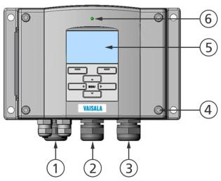
Figure 1 Transmitter Body
The following numbers refer to Figure 1 above:
1= Signal + powering cable gland
2= Cable gland for optional module, or WLAN antenna connector
3= Cable gland for optional module or AC mains cable
4= Cover screw (4 pcs)
5= Display with keypad (optional)
6= Cover LED
22 ___________________________________________________________________ M210762EN-G

Chapter 2 ___________________________________________________________ Product Overview
0604-006
Figure 2 Inside the Transmitter
The following numbers refer to Figure 2 above:
1= Service port (RS-232)
2= Dip switches for analog output settings
3= Power supply and signal wiring screw terminals
4= Relay, data logger, RS-422/485, LAN, or WLAN module
(optional)
5= Grounding connector
6= Power supply module (optional)
7= Relay, data logger, or analog output module (optional)
8= Dewpoint probe
9= Galvanic isolation module (optional)
10= Adjustment button and Manual AutoCal buttons with indicator
LED and pressure set buttons.
VAISALA________________________________________________________________________ 23
User's Guide _______________________________________________________________________
Probes and Cooling Set
0604-007
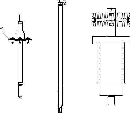
Figure 3 Probes, Cooling Set
Figure 3 above shows from left to right: DMT345 probe, DMT346 probe and the cooling set. For probe cable lengths, see Table 44 on page 165.
*) = Optional mounting flange for DMT345 probe
24 ___________________________________________________________________ M210762EN-G
Chapter 3 ________________________________________________________________ Installation
CHAPTER 3
INSTALLATION
This chapter provides you with information that is intended to help you install this product.
Selecting Location
Finding a suitable site for the dewpoint measurement probe is important for getting representative process or environmental measurements. The location of the probe should provide a good representation of the area of interest. Also select a location that is as clean as possible. Air should circulate freely around the sensor.
Mounting the Housing
The housing can be mounted either without the mounting plate or with optional mounting plates.
Standard Mounting without Mounting
Plate
Mount the housing without the mounting plate by fastening the transmitter to the wall with 4 screws, for example, M6 (not provided).
0804-066 |
Figure 4 Standard Mounting
VAISALA________________________________________________________________________ 25
User's Guide _______________________________________________________________________
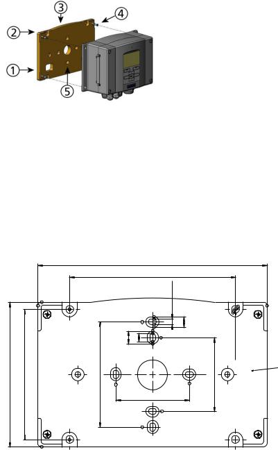
Wall Mounting with Wall Mounting Kit
When mounting with wall mounting kit the mounting plate (Vaisala order code: 214829) can be installed directly on wall or onto a standard wall box (also US junction box). When wiring through back wall, remove the plastic plug from the wiring hole in the transmitter before mounting.
0604-009
Figure 5 Mounting with Wall Mounting Kit
The following numbers refer to Figure 5 above:
1= Plastic mounting plate
2= Mount the plate to wall with 4 screws M6 (not provided)
3= Arched side up
4= Fasten the transmitter to the mounting plate with 4 fixing screws M3 (provided)
5 |
= |
Holes for wall/junction box mounting |
|
||||
|
|
|
|
|
183 (7.20) |
|
|
|
|
|
|
|
133 (5.24) |
|
|
|
|
|
(0.41) |
6.5 (0.26) |
4.5 (0.18) |
8.5 (0.33) |
(0.24) |
116 (4.57) |
104 (4.09) |
84 (3.30) |
10.5 |
|
|
59 (2.32) |
Thickness |
|
|
9.5 (0.37) |
|||||
59 (2.32) |
Ø6.2 |
||||||
|
|
|
|
|
|
||
0804-065
Figure 6 Dimensions of the Plastic Mounting Plate (mm/inch)
26 ___________________________________________________________________ M210762EN-G
Chapter 3 ________________________________________________________________ Installation
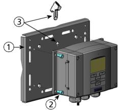
Metal mounting plate is included in rain shield with installation kit and installation kit for pole or pipeline.
0604-011
Figure 7 Mounting with Metal Wall Mounting Plate
The following numbers refer to Figure 7 above:
1= Mount the plate to wall with 4 screws M8 (not provided)
2= Fasten the transmitter to the mounting plate with 4 fixing screws
M6 (provided)
3= Note the position of the arrow when mounting. This side must be up when mounting.
VAISALA________________________________________________________________________ 27
User's Guide _______________________________________________________________________
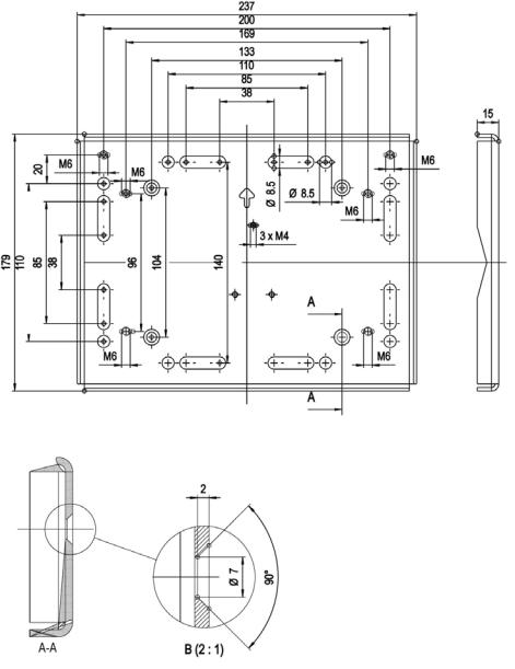
0604-012
Figure 8 Dimensions of the Metal Mounting Plate (in mm)
28 ___________________________________________________________________ M210762EN-G
Chapter 3 ________________________________________________________________ Installation
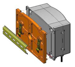
Mounting with DIN Rail Installation Kit
DIN rail installation kit includes a wall mounting kit, 2 clip-fasteners and 2 screws M4 × 10 DIN 7985 (Vaisala order code: 215094).
1.Attach two spring holders to the plastic mounting plate by using the screws provided in the installation kit.
2.Fasten the transmitter to the plastic mounting plate with 4 screws (provided).
3.Press the transmitter onto the DIN rail so that the clip-fasteners snap into the rail.
0604-013
Figure 9 Mounting with DIN Rail Installation Kit
VAISALA________________________________________________________________________ 29

User's Guide _______________________________________________________________________
Pole Installation with Installation Kit for Pole or Pipeline
Installation kit for pole or pipeline (Vaisala order code: 215108) includes the metal mounting plate and 4 mounting nuts for pole mounting. When mounting, the arrow in the metal mounting plate must point upward, see Figure 7 on page 27.
0604-014
Figure 10 Vertical Pole Installation
The following numbers refer to Figure 10 above:
1= U-bolts (2 pcs) M8 (provided) for 30 ... 102 mm poles.
2= Mounting nuts M8 (4 pcs)
0604-015
Figure 11 Horizontal Pole Installation
The following numbers refer to Figure 11 above: 1 = Mounting nuts M8 (4 pcs)
30 ___________________________________________________________________ M210762EN-G
Loading...