Vaisala WMS301, WMS302 Quick Reference Guide

Quick Reference Guide
Combined Wind Sensors
WMS301 & WMS302
–Combined wind speed & direction measurements
–Suitable for low power applications
–Fast response
–Excellent linearity
DESCRIPTION
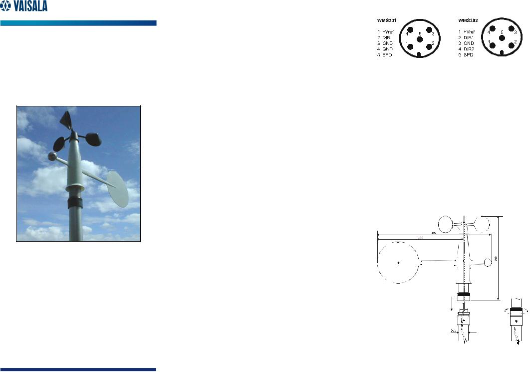
WMS301 and WMS302 are compact sized wind sensors with the wind speed and direction sensors integrated into one unit. The sensor electronics is located inside a watertight compartment providing full protection against water, dust, pollutants, and electromagnetic interference.
The cup wheel shape, dimensions, and material have been carefully designed to achieve maximum quality of measurement. The conical cups have been tested to give linear response between wind speed and angular velocity of the cup wheel. The polyamide plastic reinforced with carbon fiber guarantees a rigid structure even at the highest wind speeds.
The anemometer ball bearing assembly is composed of a wheel shaft, a pair of low friction ball bearings, and a shaft fixed magnet. A reed relay with electronics located in the body of the sensor converts the cup wheel rotation to pulses. Therefore, when properly supplied the sensor can be read practically with any data logger, either by counting the number of pulses within a fixed time period or measuring the time between successive transients. Averaging of transient intervals should be used, since two pulses with non-symmetric positioning are generated during one revolution.
The balanced wind vane is integrated in the housing, underneath the cup wheel. The circular tail is located far enough from the body and the cup wheel to avoid turbulences due to these structures. The vane assembly is of PA reinforced with glass fiber providing durable and lightweight structure with fast response and low inertia.
The angular position of the vane is detected using an axial symmetric rotating potentiometer. The potentiometer features low starting and running torque, linear arc-to-resistance transfer ratio, and long operation life.
WMS301 is equipped with a one-wiper-type potentiometer with an open cap of only 5 degrees. With constant voltage applied to the potentiometer, the output voltage is directly proportional to the azimuth angle. WMS302 has a two-wiper-type potentiometer to overcome the cap discontinuity. However, a more complex voltage-to-direction conversion process is needed.
INITIAL CHECK
After having unpacked the sensor, please check for any signs of shipping damage. Test that the vane and cup wheel rotate without friction. Before installation, use an ohmmeter to check the proper operation of SPEED output and DIR output(s) while rotating the cup wheel/vane slowly. 10 kΩ/360º and 10 kΩ/180° potentiometers are used with WMS301 and WMS302, respectively. Refer to Figure 4.
0009-020 |
Figure 1 Connectors of WMS301 and WMS302
INSTALLATION
After a proper place for wind measurement has been selected, the WMS301 sensor can be mounted to the mast as follows:
1.Fit the cable through the mounting piece and connect the cable to the sensor.
2.Fasten the mounting piece to the sensor with the plastic collar.
3.Place the sensor onto the mast.
4.Connect the ohmmeter between +Vref and the DIR pin (WMS301) or between +Vref and DIR1 pin (WMS302).
5.Keep the vane pointed to the north and turn the base until resistance reaches its minimum value. Fasten the mounting screw.
After initial installation, the sensor can be removed and remounted to its place with the plastic collar without realigning, except after potentiometer replacement.
0009-021 |
Figure 2 Mounting of WMS Sensors to the Mast
 Loading...