


 Loading...
PTB220 Series Digital
Barometers
USER'S GUIDE
M210194EN-A
AUGUST 2001
_________________________________________________________________________CONTENTS
Table of contents |
|
|
CHAPTER 1 |
GENERAL INFORMATION............................................................. |
1 |
|
Safety .............................................................................................. |
1 |
|
Warranty ......................................................................................... |
2 |
CHAPTER 2 |
PRODUCT DESCRIPTION ............................................................. |
3 |
|
Introduction.................................................................................... |
3 |
|
BAROCAP® pressure sensor....................................................... |
4 |
|
Measurement principle.................................................................. |
6 |
|
Block diagram ................................................................................ |
7 |
CHAPTER 3 |
GETTING STARTED....................................................................... |
9 |
CHAPTER 4 |
COMMISSIONING......................................................................... |
11 |
|
Operating modes ......................................................................... |
12 |
|
SMODE Selecting the sending mode....................................... |
12 |
|
MMODE Selecting the measurement mode............................. |
13 |
|
PULSE Selecting the PULSE output mode .............................. |
14 |
|
Software settings......................................................................... |
16 |
|
SERI Serial bus settings........................................................... |
16 |
|
ECHO Setting the serial bus echo on/off.................................. |
17 |
|
FORM Defining the output format............................................. |
17 |
|
EFORM Defining the error output format ................................. |
22 |
|
DFORM Defining the display format......................................... |
22 |
|
UNIT Setting the pressure and temperature units.................... |
25 |
|
HHCP Setting the height of height correction........................... |
25 |
|
AVRG Setting the averaging time............................................. |
26 |
|
INTV Setting the output interval................................................ |
27 |
|
ADDR Setting the barometer address (for POLL mode) .......... |
27 |
|
SCOM User specific SEND command ..................................... |
28 |
|
PSTAB Setting the pressure stability indicator......................... |
29 |
|
PLARM Setting the pressure alarm levels................................ |
30 |
|
PDMAX Setting the pressure difference limit ........................... |
30 |
|
KEYLOCK Setting the keyboard lock on/off ............................. |
32 |
|
Hardware settings........................................................................ |
33 |
CHAPTER 5 |
INSTALLATION............................................................................. |
37 |
|
Mounting....................................................................................... |
37 |
|
Electrical connections................................................................. |
38 |
|
Grounding..................................................................................... |
40 |
|
Pressure connections ................................................................. |
41 |
CHAPTER 6 |
OPERATING.................................................................................. |
43 |
|
RUN and STOP modes ................................................................ |
43 |
|
R Starting the continuous output .............................................. |
44 |
|
S Stopping the output ............................................................... |
44 |
|
SEND Outputting a single message only ................................. |
45 |
|
V Verification message............................................................. |
45 |
|
DNOS Self-diagnostics............................................................. |
45 |
VAISALA ___________________________________________________________________________I
USER'S GUIDE_______________________________________________________________________
|
TRACK Setting the pressure tracking mode on/off.................. |
46 |
|
PLIM Pressure limit listing........................................................ |
46 |
|
RESET Resetting the barometer ............................................. |
47 |
|
POLL mode .................................................................................. |
48 |
|
SEND Outputting one single message .................................... |
48 |
|
OPEN Setting a barometer from POLL mode to STOP mode. 49 |
|
|
CLOSE Setting a barometer from STOP mode to POLL mode49 |
|
|
SEND mode.................................................................................. |
50 |
|
PULSE mode................................................................................ |
51 |
|
Operating the local display and keyboard................................ |
51 |
CHAPTER 7 |
ADJUSTMENT AND CALIBRATION........................................... |
55 |
|
Introduction ................................................................................. |
55 |
|
CORR Listing linear and multipoint corrections ....................... |
57 |
|
LC Linear corrections............................................................... |
59 |
|
MPC Multipoint corrections ...................................................... |
60 |
|
Offset and gain adjustment........................................................ |
61 |
|
LCI Entering linear corrections................................................. |
61 |
|
Multipoint adjustment................................................................. |
62 |
|
MPCI Entering multipoint corrections ...................................... |
62 |
|
Calibration ................................................................................... |
63 |
|
CALD Storing the new date of calibration................................ |
64 |
CHAPTER 8 |
SELF-TESTING AND PROBLEM HANDLING ............................ |
65 |
|
Returning the serial communication parameters .................... |
65 |
|
Diagnostic commands................................................................ |
66 |
|
? Basic information on the barometer settings ....................... |
66 |
|
VERS Software version ........................................................... |
67 |
|
SNUM Serial number ............................................................... |
67 |
|
ERRS Error message output .................................................. |
67 |
|
TEST n Testing transducer operation...................................... |
68 |
|
C n Listing transducer coefficients........................................... |
69 |
|
PTEST Testing pulse output mode.......................................... |
69 |
CHAPTER 9 |
TECHNICAL SPECIFICATIONS .................................................. |
71 |
|
Barometric pressure ................................................................... |
71 |
|
Operating range ....................................................................... |
71 |
|
Accuracy ...................................................................................... |
71 |
|
General......................................................................................... |
72 |
|
Mechanics.................................................................................... |
73 |
|
Electromagnetic compatibility................................................... |
73 |
|
Options......................................................................................... |
74 |
|
Accessories ................................................................................. |
74 |
APPENDIX A |
HARDWARE CONFIGURATIONS............................................... |
77 |
APPENDIX B |
PIN ASSIGNMENTS..................................................................... |
79 |
APPENDIX C |
RS232C/TTL LEVEL SERIAL INTERFACE ................................ |
81 |
APPENDIX D |
PULSE OUTPUT MODE............................................................... |
83 |
APPENDIX E |
ANALOG OUTPUT....................................................................... |
87 |
|
Pin assignment............................................................................ |
90 |
II_____________________________________________________________________ M210194EN-A
_________________________________________________________________________CONTENTS
APPENDIX F |
MULTIPLE PTB220 BAROMETERS ON RS232C |
.......................91 |
APPENDIX G |
OPTIONAL RS485/422 INTERFACE OF PTB220 BAROMETERS93 |
|
APPENDIX H |
SERIAL INTERFACE COMMANDS ............................................. |
97 |
|
Commissioning commands........................................................ |
97 |
|
Operating commands.................................................................. |
97 |
|
Maintenance commands ............................................................. |
98 |
|
Diagnostic commands ................................................................ |
98 |
APPENDIX I |
CHECKSUM .................................................................................. |
99 |
APPENDIX J |
PRESSURE TENDENCY ............................................................ |
101 |
APPENDIX K |
ERROR MESSAGES................................................................... |
102 |
APPENDIX L |
SPECIAL EMULATION MODE................................................... |
103 |
|
PA11A.......................................................................................... |
103 |
|
P Mode.................................................................................... |
103 |
|
Automode ............................................................................... |
104 |
|
Setra 470 ..................................................................................... |
105 |
APPENDIX M |
PRESSURE CONVERSION CHART .......................................... |
107 |
VAISALA __________________________________________________________________________III

CHAPTER 1_______________________________________________________ GENERAL INFORMATION
CHAPTER 1 GENERAL INFORMATION
Safety
Throughout the manual important instructions regarding the safety considerations are focused as follows.
WARNING Warning denotes a hazard. It calls attention to a procedure, practice, condition or the like, which, if not correctly performed or adhered to, could result in injury to or death of personnel.
CAUTION |
Caution denotes a hazard. It calls attention to a procedure, practice, |
|
condition or the like, which, if not correctly performed or adhered to, |
|
could result in damage to or destruction of part or all of the product. |
|
|
NOTE |
Note highlights important information. It calls attention to an essential |
|
procedure, practice, condition or the like. |
|
|
VAISALA __________________________________________________________________________ 1
USER'S GUIDE_______________________________________________________________________
Warranty
Vaisala hereby represents and warrants all Products manufactured by Vaisala and sold hereunder to be free from defects in workmanship or material during a period of twelve (12) months from the date of delivery save for products for which a special warranty is given. If any Product proves however to be defective in workmanship or material within the period herein provided Vaisala undertakes to the exclusion of any other remedy to repair or at its own option replace the defective Product or part thereof free of charge and otherwise on the same conditions as for the original Product or part without extension to original warranty time. Defective parts replaced in accordance with this clause shall be placed at the disposal of Vaisala.
Vaisala also warrants the quality of all repair and service works performed by its employees to products sold by it. In case the repair or service works should appear inadequate or faulty and should this cause malfunction or nonfunction of the product to which the service was performed Vaisala shall at its free option either repair or have repaired or replace the product in question. The working hours used by employees of Vaisala for such repair or replacement shall be free of charge to the client. This service warranty shall be valid for a period of six (6) months from the date the service measures were completed.
This warranty is however subject to following conditions:
a)A substantiated written claim as to any alleged defects shall have been received by Vaisala within thirty (30) days after the defect or fault became known or occurred, and
b)the allegedly defective Product or part shall, should Vaisala so require, be sent to the works of Vaisala or to such other place as Vaisala may indicate in writing, freight and insurance prepaid and
properly packed and labelled, unless Vaisala agrees to inspect and repair the Product or replace it on site.
This warranty does not however apply when the defect has been caused through
a)normal wear and tear or accident;
b)misuse or other unsuitable or unauthorized use of the Product or negligence or error in storing, maintaining or in handling the Product or any equipment thereof;
c)wrong installation or assembly or failure to service the Product or otherwise follow Vaisala's service instructions including any repairs or installation or assembly or service made by unauthorized personnel not approved by Vaisala or replacements with parts not manufactured or supplied by Vaisala;
d)modifications or changes of the Product as well as any adding to it without Vaisala's prior authorization;
e)other factors depending on the Customer or a third party.
Notwithstanding the aforesaid Vaisala's liability under this clause shall not apply to any defects arising out of materials, designs or instructions provided by the Customer.
This warranty is expressly in lieu of and excludes all other conditions, warranties and liabilities, express or implied, whether under law, statute or otherwise, including without limitation ANY IMPLIED WARRANTIES OF MERCHANTABILITY OR OF FITNESS FOR A PARTICULAR PURPOSE and all other obligations and liabilities of Vaisala or its representatives with respect to any defect or deficiency applicable to or resulting directly or indirectly from the Products supplied hereunder, which obligations and liabilities are hereby expressly cancelled and waived. Vaisala's liability shall under no circumstances exceed the invoice price of any Product for which a warranty claim is made, nor shall Vaisala in any circumstances be liable for lost profits or other consequential loss whether direct or indirect or for special damages.
2 ____________________________________________________________________ M210194EN-A
CHAPTER 2___________________________________________________ PRODUCT DESCRIPTION
CHAPTER 2 PRODUCT DESCRIPTION
Introduction
The PTB220 series barometers are fully compensated digital barometers designed to cover a wide range of environmental pressure and temperature. They can be used successfully both in accurate pressure measurement applications at room temperature and in demanding automatic weather station applications.
The PTB220 series digital barometers use the BAROCAP® silicon capacitive absolute sensor developed by Vaisala for barometric pressure measurement applications.
The measurement principle of the PTB220 series digital barometers is based on an advanced RC oscillator and three reference capacitors against which the capacitive pressure sensor and the capacitive temperature compensation sensor are continuously measured. The microprocessor of the barometer performs compensation for pressure linearity and temperature dependence.
The pressure and temperature adjustment in the PTB220 consists of seven temperature levels over the operating temperature range of the barometer and of six to eleven pressure levels over the operating pressure range of the barometer at each temperature level. The calculated individual basic pressure and temperature adjustment coefficients are stored in the EEPROM of each pressure transducer. The user cannot change these basic factory adjustments.
The multipoint fine adjustment for pressure and the final pressure calibration of the PTB220 Class A barometers is done using a manual Ruska 2465 dead-weight tester. The multipoint fine adjustment and calibration of the Class B barometers is done automatically using electronic working standards.
VAISALA __________________________________________________________________________ 3
USER'S GUIDE_______________________________________________________________________
The PTB220 series digital barometers are available with one, two or three pressure transducers. Although one pressure transducer is usually the most appropriate configuration, some applications may benefit from additional pressure transducers. Two or three pressure transducers provide for a self-diagnostic feature: the user can set an alarm limit within which the pressure transducers must agree for reliable measurement. The PTB220 series barometers can also be configured to measure two separate pressures.
A local LCD display on the cover is also available as a configuration option. The display has a backlight, which makes the display easy to read at any light conditions. The display has two rows and it can simultaneously indicate the barometric pressure, the three-hour pressure trend and the WMO pressure tendency code.
The user can define various specific application settings, such as serial bus settings, averaging time, output interval, output format, display format, error message field, pressure unit and pressure resolution. It is also possible to select different sending modes for power-up situation such as the free running mode, the stand-by mode and a mode with one automatically sent message. A fast measurement mode with ten measurements per second can also be selected. The factory settings have been chosen so that both a fast settling time and a high resolution are achieved. In applications where fast settling time is not required, longer averaging times are recommended to reduce environmetal pressure noise.
As a standard, there are RS 232C full duplex and bidirectional TTL level serial interface in the barometer. In addition the user can select either an RS 485/422 two-wire half duplex serial interface or a pulse output interface with user selectable pulse rate, pressure resolution and pressure offset.
The PTB220 series digital barometers are traceable to National
Institute of Standards and Technology (NIST) in the USA.
BAROCAP® pressure sensor
The PTB220 digital barometers use the BAROCAP® silicon capacitive absolute pressure sensor developed by Vaisala for barometric pressure measurement applications. The BAROCAP® sensor has excellent hysteresis and repeatability characteristics, low temperature dependence and a very good long-term stability. The ruggedness of the BAROCAP® sensor is outstanding and the sensor is resistant to mechanical and thermal shocks.
4 ____________________________________________________________________ M210194EN-A
CHAPTER 2___________________________________________________ PRODUCT DESCRIPTION
|
Silicon diaphragm |
Thin film metallization |
Silicon |
Glass
 Silicon
Vacuum gap
FIGURE 2-1 The BAROCAP® pressure sensor
The BAROCAP® pressure sensor consists of two layers of single crystal silicon having a layer of glass between them. The thinner silicon layer is etched on both sides to create an integrated vacuum reference chamber for the absolute pressure sensor and to form a pressure sensitive silicon diaphragm. The thicker silicon layer is the rigid base plate of the sensor and it is clad with a glass dielectric. The thinner piece of silicon is electrostatically bonded to the glass surface to form a strong and hermetic bond. Thin film metallization has been deposited to form a capacitor electrode inside the vacuum reference chamber; the other electrode is the pressure sensitive silicon diaphragm.
The coefficients of thermal expansion of silicon and glass materials used in the BAROCAP® pressure sensor are carefully matched together in order to minimize the temperature dependence and to maximize the long-term stability. The BAROCAP® pressure sensor is designed to achieve zero temperature dependence at 1000 hPa and its long-term stability has been maximized by thermal ageing at an elevated temperature.
The BAROCAP® capacitive pressure sensor features a wide dynamic range and no self-heating effect. The excellent hysteresis and repeatability characteristics are based on the ideal spring characteristics of single crystal silicon. In the BAROCAP® pressure sensor, the silicon material is exerted to only few percent of its whole elastic range.
VAISALA __________________________________________________________________________ 5
USER'S GUIDE_______________________________________________________________________
Measurement principle
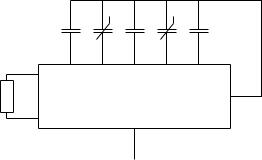
The measurement principle of the PTB220 series digital barometers is based on an advanced RC oscillator with three reference capacitors against which the capacitive pressure sensor and the capacitive temperature compensation sensor are continuously measured. A multiplexer connects each of the five capacitors to the RC oscillator one at a time and five different frequencies are measured during one measurement cycle (FIGURE 2-2 )
CP |
|
CT |
C1 |
C2 |
C3 |
R
Fout
FIGURE 2-2 RC-oscillator with five capacitors
The RC oscillator is designed to attenuate changes in stray impedance and to achieve excellent measurement stability with time. Vaisala’s electronic measurement principle emphasizes in the first place stability over a wide environmental temperature and relative humidity range and over a long period of time; yet it can achieve fast measurement speed and high resolution at the same time.
In the fast measurement mode, a special measurement algorithm is used. In this mode only the frequency from the BAROCAP pressure sensor is measured continuously while the frequencies from the three reference capacitors and from the thermal compensation capacitor are updated only every 30 seconds. This is quite justifiable as the changes in the reference capacitors can be considered negligible over any periods of time, and the internal temperature of the barometer remains stable enough over a few tens of seconds. The fast measurement mode achieves a speed of ten measurements per second at 1 pascal resolution. Each measurement represents the pressure average during the last 100 ms. When the reference frequencies are measured every 30 seconds the outputting stops for a short moment and typically one measurement is lost during this time. The fast measurement mode can be used only in barometers with one pressure transducer and in full duplex communication.
6 ____________________________________________________________________ M210194EN-A
CHAPTER 2___________________________________________________ PRODUCT DESCRIPTION
Block diagram
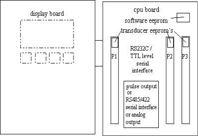
The PTB220 series digital barometers consist of a CPU board and 1, 2 or 3 pressure transducers (P1, P2 and P3). The number of pressure transducers is order specific and the configuration cannot be changed by the user. Usually the pressure transducers are connected to the same pressure port. However, in case of two pressure transducers, the barometer can have also two pressure ports, one for each transducer. The various hardware configurations are illustrated on page 77.
The PTB220 series barometers always have a RS 232C full duplex and a bidirectional TTL level serial interface. In addition, the barometers have either a pulse output interface or an RS 485/422 twowire half duplex serial interface. The RS 485/422 interface is a separate optional module inside the barometer. This interface module is order specified and installed at the factory only. There is also an optional factory set analog output module available. A LCD display with backlight is also a possible configuration option.
The block diagram of the PTB220 series barometers is shown in
FIGURE 2-3
FIGURE 2-3 Block diagram of the PTB220 barometers
VAISALA __________________________________________________________________________ 7
CHAPTER 3___________________________________________________________ GETTING STARTED
CHAPTER 3 GETTING STARTED
As the PTB220 series digital barometers always have an RS 232C serial interface, the user is requested to use this interface when operating the barometer for the first time. The RS 232C is the most useful and reliable interface for commissioning the barometers with various software settings.
The RS 232C serial interface of the PTB220 barometers does not provide handshaking lines (such as DSR, CTS or DTR). If the host system requires handshaking lines, appropriate external connections have to be made in order to enable the communication with a PTB220. See Appendix on page 81 for more details on how to connect the handshaking lines.
NOTE |
1. |
The sending of PTB220 is controlled with XON/XOFF (software |
|
|
handshaking) |
|
2. |
The buffer of the barometer can be cleared with <cr>. |
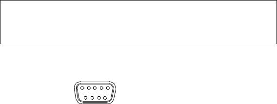
The RS 232C serial interface and power supply pin assignment is as follows:
5 4 3 2 1
9 8 7 6
FIGURE 3-1 |
9-pin female subD-connector |
|
|
PIN |
SIGNAL |
2 |
TX |
3 |
RX |
5 |
ground for the RS 232C |
7 |
ground for supply voltage |
9 |
supply voltage (10...30 VDC) |
FIGURE 3-2 |
RS 232C and power supply pins |
VAISALA __________________________________________________________________________ 9
USER'S GUIDE_______________________________________________________________________
The factory settings of the PTB220 series barometers are the following:
TABLE 3-1 Serial interface factory settings
Baud rate |
9600 |
Parity |
even |
Data bits |
7 |
Stop bits |
1 |
Duplex |
full duplex |
After having made the electrical connections, switch the power on, and the barometer responds indicating the barometer type and the software version.
PTB220 / 2.02
>
The barometer is now ready to respond to any command, for example to commands R, S or SEND (see page 43).
If there is a LCD display cover, at power-up the display will first show the barometer type and the software version. Then it switches to display the barometric pressure reading as defined with the DFORM command. The keyboard of the display cover can be used to inspect and change the parameters available (see page 51).
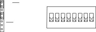
Should there be any problems please check the jumper settings in connector X15 and the settings in dip switch S1 inside the barometer. The settings should be as indicated in the figures below.
RX/RXD RXD
TX
ON |
S1 |
TXD |
OFF |
|
TXD |
SW1 SW3 SW5 SW7 |
|
X15 |
||
SW2 SW4 SW6 SW8 |
FIGURE 3-3 Basic RS 232C jumper and dip switch S1 settings
10 ___________________________________________________________________ M210194EN-A
CHAPTER 4_____________________________________________________________ COMMISSIONING
CHAPTER 4 COMMISSIONING
TABLE 4-1summarizes the commands used to commission the PTB220 series digital barometers. The commands are not case sensitive except for the SCOM command.
TABLE 4-1 |
Commissioning commands |
|
|
|
|
Function |
|
Command |
sending mode |
SMODE |
|
measurement mode |
MMODE |
|
pulse mode settings |
PULSE |
|
serial bus settings |
SERI |
|
echo on / off |
|
ECHO |
output format |
|
FORM |
pressure resolution |
FORM |
|
pressure trend |
FORM |
|
pressure tendency |
FORM |
|
error status |
|
FORM |
stability indicator |
FORM |
|
checksum |
|
FORM |
height of height correction |
HHCP |
|
error output format |
EFORM |
|
display format |
DFORM |
|
pressure and temperature units |
UNIT |
|
averaging time |
AVRG |
|
setting output interval |
INTV |
|
address of the barometer |
ADDR |
|
user specific SEND command |
SCOM |
|
pressure stability indicator |
PSTAB |
|
pressure alarm levels (HI and LO) |
PLARM |
|
pressure difference limit |
PDMAX |
|
keyboard locking |
KEYLOCK |
|
The commissioning commands can be divided in two sections: the operating mode commands and the software setting commands.
VAISALA _________________________________________________________________________ 11

USER'S GUIDE_______________________________________________________________________
Operating modes
The first thing to do is to select the desired sending mode for the barometer. This is done with the command SMODE. There are available the normal or the fast measurement mode or the pulse output mode. These selections are made with MMODE and PULSE commands.
SMODE Selecting the sending mode
SMODE x <cr>
where:
x = STOP, RUN, SEND or POLL
The SMODE command is used to set or inspect the sending mode of the barometer. The PTB220 series digital barometers have four sending modes: STOP, RUN, SEND and POLL.
In STOP mode (see page 43), after power-up the barometer outputs its type and software version and then waits for further commands.
In RUN mode (see page 43), continuous outputting starts automatically from power-up.
In SEND mode (see page 50) a single message is automatically output after power-up.
POLL mode (see page 48) allows the communication with multiple barometers or other digital instruments connected to one serial bus. Echo is automatically off in the POLL mode.
Examples:
>smode <cr> |
|
Serial mode |
: STOP |
>smode run <cr> |
|
Serial mode |
: RUN |
>smode send <cr> |
|
Serial mode |
: SEND |
>smode poll <cr> |
|
Serial mode |
: POLL |
>smode stop <cr> |
|
Serial mode |
: STOP |
>reset<cr> |
|
12 ___________________________________________________________________ M210194EN-A

CHAPTER 4_____________________________________________________________ COMMISSIONING
NOTE |
Remember to give the RESET command to initialize the new sending |
|
mode. |
|
|
MMODE Selecting the measurement mode
MMODE x <cr>
where:
x = NORMAL or FAST
The MMODE command is used to set or inspect the measurement mode of the barometer. In the normal measurement mode, the barometer measures the capacitance of each of the five capacitive components of the pressure transducer (see page 6). This is the standard operating mode of the PTB220 series digital barometers.
In the fast measurement mode, the barometer measures mainly the capacitance of the BAROCAP pressure sensor and results in a faster measurement speed (approximately 10 measurements per second). This measurement mode can be used only with the barometers having one pressure transducer and full duplex communication.
MMODE selection is protected by switch SW4 (see FIGURE 4-1). The switch SW4 is normally in DISABLE position (OFF). Turn the switch to ENABLE position (ON) to be able to make a new MMODE selection.
ON |
S1 |
OFF
SW1 SW3 SW5 SW7
SW2 SW4 SW6 SW8
FIGURE 4-1 Switch SW4 in ENABLE position (ON)
Example of selecting the fast measurement mode:
>mmode <cr> |
|
|
Meas |
mode |
: NORMAL |
>mmode fast <cr> |
||
Meas |
mode |
: FAST |
>mtim 32 <cr> |
|
|
VAISALA _________________________________________________________________________ 13

USER'S GUIDE_______________________________________________________________________
|
Mtim |
: |
32 |
|
>filt off <cr> |
|
|
|
Filter |
: OFF |
|
|
>reset <cr> |
|
|
|
|
||
NOTE |
Remember to give the RESET command to initialize the new |
||
|
measurement mode. |
|
|
|
|
||
|
The measurement time (mtim) setting of 32 is recommended in order |
||
|
to achieve the best output stability at the speed of 10 measurements |
||
|
per second. The filter command ensures that no numerical filtering is |
||
|
performed in the fast measurement mode. The MTIM and FILT |
||
|
commands are used only together with the MMODE FAST command. |
||
|
In the NORMAL measurement mode, the AVRG command replaces |
||
|
the MTIM and FILT commands in the PTB220 series digital |
||
|
barometers. |
|
|
|
|
||
NOTE |
Always remember to return the switch SW4 to write DISABLE |
||
|
position (OFF). |
|
|
|
|
|
|
PULSE Selecting the PULSE output mode
PULSE a s r o <cr>
where: |
|
|
|
a |
= |
ON or OFF |
(activation/deactivation) |
s |
= |
SLOW or FAST (speed) |
|
r |
= |
LOW or HIGH |
(resolution) |
o |
= |
pressure offset |
(hPa/mbar units only) |
The PULSE command is used to activate or deactivate the pulse ouput mode and to set or inspect the desired parameters. SLOW/FAST selection affects the pulse rate: SLOW speed equals to 5 kHz pulse rate and FAST speed equals to 50 kHz pulse rate. LOW resolution equals to 0.1 hPa/mbar pressure resolution and HIGH resolution equals to 0.01 hPa/mbar pressure resolution. In order to minimize the number of output pulses the user can define an offset pressure so that pulse outputting starts from the selected pressure level.
14 ___________________________________________________________________ M210194EN-A
CHAPTER 4_____________________________________________________________ COMMISSIONING
NOTE |
The pulse output mode can be used with hPa/mbar pressure units |
|
only! |
|
|
Example of software settings for the pulse output mode:
|
>pulse <cr> |
|
|
|
|
OFF |
SLOW LOW |
0.0 |
|
|
>pulse on slow low <cr> |
|
||
|
ON |
SLOW LOW |
0.0 |
|
|
>pulse on fast high -800 <cr> |
(note the minus sign) |
||
|
ON |
FAST HIGH |
-800.0 |
|
|
>pulse off <cr> |
|
|
|
|
OFF |
FAST HIGH |
-800.0 |
|
|
> |
|
|
|
|
The operation of pulse output mode can be tested through the RS232C |
|||
|
serial interface using the PTEST command (see page 69). |
|||
|
In addition to the above mentioned software settings, the user must |
|||
|
finally set the switch SW3 to position ON (see Hardware settings on |
|||
|
page 33) for the barometer to start to wait for an external trigger pulse. |
|||
|
See page 83 for quick reference information on how to set and use the |
|||
|
pulse output mode of the PTB220 series digital barometers. |
|||
|
|
|||
NOTE |
In case of an error in a PTB220 series barometer, there will be no |
|||
|
pulse output from the barometer despite an external trigger pulse. |
|||
|
This error handling technique ensures that a host system cannot |
|||
|
receive erroneous pressure readings from a PTB220 series |
|||
|
barometer. |
|
|
|
|
|
|
|
|
VAISALA _________________________________________________________________________ 15
USER'S GUIDE_______________________________________________________________________
Software settings
SERI Serial bus settings
|
|
SERI b p d s x <cr> |
|
where: (* = factory setting) |
|
||
b |
= |
baud rate (300, 600, 1200, 2400, 4800, 9600*) |
|
p |
= |
parity (E = even*, O = odd, N = none) |
|
d |
= |
data bits (7* or 8) |
|
s |
= |
stop bits (1* or 2) |
|
x |
= |
duplex (F = full* or H = half) |
|
<cr> |
= |
carriage return is generated by the ENTER or RETURN |
|
|
|
key of the host computer |
|
The SERI command is used to set or inspect the serial bus settings of the barometer.
Examples:
>seri <cr> 9600 E 7 1 F
>seri 1200 N 8 1 H <cr> 1200 N 8 1 H
>reset <cr>
PTB220 / 2.02 >seri 2400 <cr> 2400 N 8 1 H >seri F <cr> 2400 N 8 1 F >reset <cr>
PTB220 / 2.02
>
Always give the RESET command after the SERI command to activate the new serial bus settings.
The following bus settings do not work with the incorporated Intel 8051 microprocessor. They are modified by the barometer:
N 7 1 |
→ |
N 7 2 |
E 8 2 |
→ |
E 8 1 |
O 8 2 |
→ |
O 8 1 |
16 ___________________________________________________________________ M210194EN-A

CHAPTER 4_____________________________________________________________ COMMISSIONING
The RS485/422 interface of the PTB220 series digital barometers is a non-isolated two-wire half-duplex interface. See page 93 for quick reference information on how to use the RS485/422 interface of the PTB220 series digital barometers.
ECHO Setting the serial bus echo on/off
ECHO x <cr>
where:
x = ON or OFF
The ECHO command is used to set or inspect the echoing condition of the barometer. In OFF mode the barometer does not output the '>' prompt character.
Examples:
>echo <cr> |
|
|
Echo |
: |
ON |
>echo off <cr> |
|
|
Echo |
: |
OFF |
... |
|
|
echo on <cr> |
|
(text invisible) |
Echo |
: |
ON |
> |
|
|
FORM Defining the output format
The FORM command is used to set or inspect the output format of the barometer. See the examples in the next page.
FORM <cr>
The user can define the following fields into the output format:
amount of decimals |
give number of decimals before a |
|
quantity. Giving 4.2 before the |
|
pressure quantity outputs a reading |
|
with the following form: 1013.12 |
VAISALA _________________________________________________________________________ 17
USER'S GUIDE_______________________________________________________________________
pressure quantities
height corrected pressure pressure trend *) pressure tendency temperature quantities *)
pressure and temperature units address of the barometer error status
stability indicator checksums number fields text fields
ASCII characters: CR
LF
TAB
nnn ASCII code
P1 (reading of the transducer 1),
P2 (transducer 2), P3 (transducer 3), P (average)
HCP (see also page 25) TREND (three-hour trend) A (see page 101 for details) T1, T2, T3
UU, UUU, UUUU,UUUUU ADDR (uses two characters) ERR (uses three characters) OK (uses three characters)
CS2, CS4
n.m where: n = 0 - 9, m = 0- 9 within “ “ characters
#r
#n
#t
#nnn
*) The PTB220 barometer cannot output + sign for pressure trend or temperature reading; a space is output instead.
18 ___________________________________________________________________ M210194EN-A
CHAPTER 4_____________________________________________________________ COMMISSIONING
Examples of different ways of setting the output format:
1. To output the pressure reading.
>form <cr>
4.2 P " " UUUU #r #n ? <cr>
>send <cr> 1020.30 hPa
>
2. To output the transducer values (P1,P2,P3) separately and the average value (P).
>form |
<cr> |
|
4.2 P |
" " UUUU #r #n |
|
? 4.2 |
P1 " " P2 |
" " P3 " " P " " UUU #r #n <cr> |
>send |
<cr> |
|
1020.31 1020.32 |
1020.33 1020.32 hPa |
|
> |
|
|
3. To output pressure reading followed with three-hour trend.
>form |
<cr> |
|
|
|
4.2 P |
" |
" UUUU #r #n |
|
|
? 4.2 |
P |
" " |
UUU " " 2.1 TREND " " UUU #r #n <cr> |
|
>send |
<cr> |
|
|
|
1020.30 |
hPa |
**.* hPa |
(date not available) |
|
>send |
<cr> |
|
|
|
1020.30 |
hPa |
-1.2 hPa |
|
|
4. To output pressure reading followed with three-hour trend and pressure tendency.
>form |
<cr> |
|
|
|
|
4.2 P |
" |
" UUUU #r #n |
|
||
? 4.2 |
P |
" " |
UUU " " 2.1 TREND " " UUU " " A #r #n <cr> |
||
>send |
<cr> |
|
|
|
|
1020.30 |
hPa |
**.* hPa * |
(date not available) |
||
>send |
<cr> |
|
|
|
|
1020.30 |
hPa |
-1.2 |
hPa 7 |
|
|
>send |
<cr> |
|
|
|
|
1020.30 |
hPa |
1.2 |
hPa 2 |
(no + sign) |
|
5. To output the pressure from tranducer P1 followed with temperature reading.
>form |
<cr> |
|
4.2 P |
" " UUUU #r #n |
|
? 4.2 |
P1 " " UUU " " 3.1 T1 " " UU #r #n <cr> |
|
>send |
<cr> |
|
1020.30 hPa 23.4 'C |
(no + sign) |
|
> |
|
|
VAISALA _________________________________________________________________________ 19
USER'S GUIDE_______________________________________________________________________
6. To output the average pressure reading in the units of inHg .
>form |
<cr> |
|
4.2 P |
" |
" UUU #r #n |
? 2.4 |
P |
" " UUUU #r #n <cr> |
>unit |
inHg <cr> |
|
P unit |
|
: inHg |
>send |
<cr> |
|
30.1234 |
inHg |
|
> |
|
|
7. Adding a text field, giving the address and outputting the pressure reading from a identified barometer.
>form |
<cr> |
|
|
|
4.2 P |
" |
" UUUU #r #n |
|
|
? "Barometer |
" ADDR " " 4.2 P " " UUU #r #n <cr> |
|||
>addr |
7 |
<cr> |
|
|
Address |
|
: |
7 |
|
>send |
7 |
<cr> |
|
|
Barometer 07 |
1020.30 |
hPa |
||
> |
|
|
|
|
8. To output the average pressure reading and the error status.
>form |
<cr> |
|
|
|
4.2 P |
" |
" UUUU #r #n |
|
|
? 4.2 |
P |
" " |
UUU " " ERR #r #n <cr> |
|
>send |
<cr> |
|
|
|
1020.30 |
hPa |
0 |
(no error found) |
|
>send |
<cr> |
|
|
|
1020.30 |
hPa |
1 |
(some error has occurred) |
|
> |
|
|
|
|
9. To output the transducer values (P1,P2,P3) separately and the average value (P). Indicates errors if the maximum pressure difference between the transducers is exceeding the defined value.
The two-or three-digit error field in the end of the line is expressing the error state of the transducers. Number 1 means error and number 0 normal state. The first digit shows state of transducer 1 (P1), second digit shows state of transducer 2 (P2) and the third digit shows transducer 3 (P3).
>form |
<cr> |
|
|
|
|
4.2 P |
" |
" UUUU #r #n |
|
|
|
? 4.2 |
P1 " " P2 |
" " P " |
" UUU " " ERR #r #n <cr> |
||
>send |
<cr> |
|
|
|
|
1020.30 |
1020.32 |
1020.31 |
hPa 00 |
|
|
>send |
<cr> |
|
|
|
|
1020.30 |
1022.30 |
1021.30 |
hPa 11 |
(Pd max error) |
|
> |
|
|
|
|
|
20 ___________________________________________________________________ M210194EN-A
CHAPTER 4_____________________________________________________________ COMMISSIONING
>form |
<cr> |
|
|
|
|
|
4.2 P |
" |
" UUUU #r #n |
|
|
|
|
? 4.2 |
P1 " " P2 |
" " P3 " " P " " UUU " " ERR #r #n <cr> |
||||
>send |
<cr> |
|
|
|
|
|
1020.30 |
1020.31 |
1020.32 |
1020.31 |
hPa 000 |
|
|
>send |
<cr> |
|
|
|
|
|
1020.30 |
1022.31 |
1020.32 |
1020.31 |
hPa 010 |
(Pd max error) |
|
> |
|
|
|
|
|
|
>form |
<cr> |
|
|
|
|
|
4.2 P |
" |
" UUUU #r #n |
|
|
|
|
? 4.2 |
P1 " " P2 |
" " P3 " " P " " UUU " " ERR #r #n <cr> |
||||
>send |
<cr> |
|
|
|
|
|
1020.30 |
1020.31 |
1020.32 |
1020.31 |
hPa 000 |
|
|
>send |
<cr> |
|
|
|
|
|
1020.30 |
1022.31 |
1024.32 |
1022.31 |
hPa 111 |
(Pd max error) |
|
> |
|
|
|
|
|
|
10. To output the pressure reading and the stability state.
>form |
<cr> |
|
|
|
4.2 P |
" |
" UUUU #r #n |
|
|
? 4.2 |
P |
" " |
UUU OK #r #n <cr> |
|
>send |
<cr> |
|
|
|
1020.30 |
hPa |
OK |
(good stability) |
|
>send |
<cr> |
|
|
|
1020.30 |
hPa |
|
(poor stability) |
|
> |
|
|
|
|
11. To output the pressure reading and the checksums.
>form |
<cr> |
|
4.2 P |
" |
" UUUU #r #n |
? 4.2 |
P |
" " UUU " " CS2 #r #n <cr> |
>send |
<cr> |
|
1020.30 |
hPa BB |
|
> |
|
|
12. To output the pressure reading and the height corrected pressure reading.
>form
4.2 P HCP #r #n
? 4.2 P " " hcp #r #n >send
1011.12 1012.30
>
VAISALA _________________________________________________________________________ 21

USER'S GUIDE_______________________________________________________________________
EFORM Defining the error output format
EFORM <cr>
The EFORM command is used to define the user specific error output format for the serial interface. In case of an internal error, the barometer outputs the message defined with the EFORM command instead of the normal message defined with the FORM command. If the EFORM command is not defined, the barometer uses the FORM command definition with its optional error status fields.
Example of an EFORM definition:
>eform <cr>
? "ERROR" #r #n <cr>
>P <cr> |
|
|
1002.93 |
hPa OK |
(correct operation) |
>P <cr> |
|
|
ERROR |
|
(incorrect operation) |
> |
|
|
Any previous EFORM definition may be removed with the following command:
>eform * <cr>
>
DFORM Defining the display format
DFORM <cr>
The DFORM command is used to define the format for the optional LCD display. The user can define the following fields into the display format:
pressure quantities |
P1, P2, P3, P (average) |
|
height corrected pressure |
HCP (see also page 25) |
|
pressure trend *) |
TREND (three-hour trend) |
|
pressure tendency |
A (see page 101 for details) |
|
temperature quantities *) |
T1, T2, T3 |
|
pressure and temperature units |
UU, UUU, UUUU,UUUUU |
|
error status |
ERR (uses three characters) |
|
stability indicator |
OK |
(uses three characters) |
number fields |
n.m |
where: n = 0 - 9, m = 0- 9 |
text fields |
within “ “ characters |
|
22 ___________________________________________________________________ M210194EN-A
CHAPTER 4_____________________________________________________________ COMMISSIONING
*) The PTB220 barometer cannot output + sign for pressure trend or temperature reading; a space is output instead.
There are two rows containing 16 characters each; the user can define a maximum of 32 characters to be displayed. The field definitions are defined in successive order so that the first 16 characters will be displayed on the first row and the next characters on the second row.
The factory setting for the display format includes the pressure reading and the stability indicator:
CL ENT
Any previous DFORM definition may be removed and the original factory setting restored with the following command:
>dform * <cr>
>
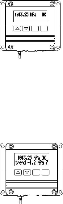
Example of setting the display format to show pressure, stability indicator, pressure trend and pressure tendency:
>dform <cr>
4.2 P " " UUUUU OK #r #n
? " " 4.2 P " " UUU OK " trend " 2.1 TREND " " UUU " " A <cr>
>
In this case, the display will look similar to the following:
CL ENT
VAISALA _________________________________________________________________________ 23

USER'S GUIDE_______________________________________________________________________
The PTB220 series barometers will show * instead of numeric values for pressure trend and pressure tendency for three hours from powerup.
In case of error in the barometer, the relevant error message will automatically appear on the second line of the display. In this case, any other information defined using the DFORM command will be replaced with an error message.
By pressing the arrow button on the left, you get a display having a horizontal bar display on the upper row. On the lower row there are three values: the value on the left shows the lower limit of the pressure range, the middle value shows the actual pressure and the value on the right shows the upper limit of the pressure range.
24 ___________________________________________________________________ M210194EN-A
Loading...