


 Loading...
USER'S GUIDE
Vaisala HUMICAP® Humidity and
Temperature Transmitter Series
HMT120
M211244EN-B
PUBLISHED BY |
|
|
|
Vaisala Oyj |
Phone (int.): |
+358 |
9 8949 1 |
P.O. Box 26 |
Fax: |
+358 |
9 8949 2227 |
FI-00421 Helsinki |
|
|
|
Finland |
|
|
|
Visit our Internet pages at www.vaisala.com.
© Vaisala 2013
No part of this manual may be reproduced, published or publicly displayed in any form or by any means, electronic or mechanical (including photocopying), nor may its contents be modified, translated, adapted, sold or disclosed to a third party without prior written permission of the copyright holder. Translated manuals and translated portions of multilingual documents are based on the original English versions. In ambiguous cases, the English versions are applicable, not the translations.
The contents of this manual are subject to change without prior notice.
This manual does not create any legally binding obligations for Vaisala towards customers or end users. All legally binding obligations and agreements are included exclusively in the applicable supply contract or the General Conditions of Sale and General Conditions of Service of Vaisala.
_________________________________________________________________________________
Table of Contents |
|
CHAPTER 1 |
|
GENERAL INFORMATION............................................................................ |
5 |
About This Manual ................................................................... |
5 |
Contents of This Manual ....................................................... |
5 |
Version Information ............................................................... |
6 |
Related Manuals ................................................................... |
6 |
Documentation Conventions ................................................. |
6 |
Safety......................................................................................... |
7 |
ESD Protection...................................................................... |
7 |
Recycling .................................................................................. |
7 |
Regulatory Compliances ......................................................... |
8 |
Patent Notice ............................................................................ |
8 |
Trademarks ............................................................................... |
8 |
License Agreement .................................................................. |
8 |
Warranty.................................................................................... |
8 |
CHAPTER 2 |
|
PRODUCT OVERVIEW.................................................................................. |
9 |
Introduction to the HMT120 Humidity and Temperature |
|
Transmitter................................................................................ |
9 |
Accessories ......................................................................... |
10 |
Fixed and Remote Probe Models........................................ |
10 |
Optional Display .................................................................. |
10 |
Interchangeable Probe........................................................ |
10 |
Constant Output Probe ....................................................... |
11 |
Transmitter Components..................................................... |
12 |
CHAPTER 3 |
|
INSTALLATION............................................................................................ |
13 |
Opening the Transmitter Cover ............................................ |
13 |
Mounting ................................................................................. |
14 |
Wall Mounting...................................................................... |
14 |
Installation with Rain Shield ................................................ |
15 |
Installation with Radiation Shield ........................................ |
16 |
Duct Installation Kit ............................................................. |
17 |
Probe Assembly with Duct Installation Kit ..................... |
18 |
Drilling Instructions for Duct Installation Kit ................... |
18 |
Probe Mounting Flange....................................................... |
19 |
Probe Mounting Clamp ....................................................... |
20 |
Connections............................................................................ |
21 |
CHAPTER 4 |
|
SERVICE PORT ........................................................................................... |
23 |
Using the Service Port ........................................................... |
23 |
Installing the Driver for the USB Cable ............................... |
23 |
VAISALA_________________________________________________________________________ 1
User's Guide _______________________________________________________________________
Terminal Application Settings.............................................. |
24 |
List of Serial Commands ....................................................... |
26 |
Device Information and Status.............................................. |
27 |
Show Device Information..................................................... |
27 |
Set/Show Available Quantities ............................................ |
28 |
Set/Show Calibration Date .................................................. |
28 |
Set/Show Calibration Information........................................ |
29 |
Show Analog Output Status ................................................ |
30 |
Show System Information ................................................... |
31 |
Show Firmware Version ...................................................... |
31 |
Serial Line Output Commands .............................................. |
31 |
Start Continuous Outputting ................................................ |
31 |
Stop Continuous Outputting ................................................ |
32 |
Set/show Output Interval ..................................................... |
32 |
Output a Reading Once....................................................... |
32 |
Calibration Commands .......................................................... |
33 |
Calibrate Humidity Measurement ........................................ |
33 |
Restore Probe RH Factory Calibration................................ |
34 |
Calibrate Temperature Measurement ................................. |
34 |
Restore Probe T Factory Calibration................................... |
35 |
Calibrate Analog Output ...................................................... |
35 |
Configuring Serial Line Operation ........................................ |
36 |
Set/Show Serial Line Settings ............................................. |
36 |
Set/Show Terminal Echo..................................................... |
36 |
Set/Show Serial Interface Mode.......................................... |
37 |
Configuring Measurement Parameters ................................ |
37 |
Set/Show Environmental Parameters ................................. |
37 |
Configuring Analog Output ................................................... |
38 |
Set/show Analog Output Error Levels ................................. |
38 |
Set/show Analog Output Quantity and Scaling ................... |
38 |
Test Analog Outputs............................................................ |
40 |
Other Commands.................................................................... |
41 |
Set/show Displayed Quantities............................................ |
41 |
Set/show Output Formatting................................................ |
42 |
Display Command List......................................................... |
43 |
Display Active Errors ........................................................... |
43 |
Save Changed Settings....................................................... |
43 |
Restore Saved Settings....................................................... |
44 |
Reset Transmitter ................................................................ |
44 |
Restore Factory Settings ..................................................... |
44 |
Set/show Output Unit........................................................... |
45 |
CHAPTER 5 |
|
MAINTENANCE............................................................................................ |
47 |
Replacing the HUMICAP® Sensor ......................................... |
47 |
Fixed and Remote Probe Models........................................ |
47 |
Removing and Fastening the Probe ..................................... |
48 |
Fixed Probe Model .............................................................. |
48 |
Remote Probe Model........................................................... |
49 |
Calibration and Adjustment................................................... |
50 |
HMT120 Push-Button Calibration........................................ |
50 |
Humidity and Temperature Adjustment............................... |
51 |
Adjustment with HM70......................................................... |
54 |
2 ____________________________________________________________________ M211244EN-B
_________________________________________________________________________________
Field Checking and Adjustment Using a Calibrated |
|
Reference Probe ............................................................ |
55 |
One-Point Adjustment Using a Calibrator...................... |
55 |
Two-Point Adjustment Using a Calibrator...................... |
56 |
LiCl-NaCl Adjustment..................................................... |
57 |
Temperature Field Check and Adjustment by Using a |
|
Calibrated Reference Probe .......................................... |
58 |
Adjustment with HMI41 ....................................................... |
59 |
Connections and Selecting the Calibrator Function....... |
60 |
Offset and Gain Adjustments ......................................... |
61 |
HMI41 as a Reference Meter.................................... |
62 |
HMI41 as a Terminal................................................. |
63 |
Troubleshooting ............................................................. |
64 |
Analog Output Tests.............................................................. |
65 |
CHAPTER 6 |
|
TROUBLESHOOTING ................................................................................. |
67 |
Error Codes............................................................................. |
67 |
Solving Typical Problems...................................................... |
68 |
Analog Output Error Notification.......................................... |
69 |
Technical Support .................................................................. |
69 |
CHAPTER 7 |
|
TECHNICAL DATA ...................................................................................... |
71 |
Options and Accessories ...................................................... |
73 |
Transmitter Dimensions ........................................................ |
74 |
APPENDIX A |
|
CALCULATION FORMULAS ...................................................................... |
77 |
Dewpoint Temperature .......................................................... |
78 |
Dew/frostpoint Temperature ................................................. |
78 |
Mixing Ratio ............................................................................ |
79 |
Absolute Humidity.................................................................. |
79 |
Enthalpy .................................................................................. |
79 |
Saturation Vapor Pressure.................................................... |
80 |
Water Vapor Pressure............................................................ |
81 |
Accuracies of Calculated Variables ..................................... |
81 |
Accuracy of Dewpoint Temperature °C............................... |
81 |
Accuracy of Mixing Ratio g/kg (Ambient Pressure 1013 |
|
mbar) ................................................................................... |
81 |
Accuracy of Wet Bulb Temperature °C ............................... |
82 |
Accuracy of Absolute Humidity g/m³ ................................... |
82 |
INDEX ........................................................................................................... |
83 |
VAISALA_________________________________________________________________________ 3
User's Guide _______________________________________________________________________
List of Figures
Figure 1 |
HMT120 Components .............................................................. |
12 |
Figure 2 |
Opening the Transmitter Cover ................................................ |
13 |
Figure 3 |
HMT120 Wall Mounting ............................................................ |
14 |
Figure 4 |
HMT120 Installation with Rain Shield....................................... |
15 |
Figure 5 |
Installation of the Probe with Radiation Shield ......................... |
16 |
Figure 6 |
Probe Installation with the Duct Installation Kit ........................ |
17 |
Figure 7 |
Assembly of the Probe with Duct Installation Kit ...................... |
18 |
Figure 8 |
Drilling Instructions ................................................................... |
18 |
Figure 9 |
Optional Probe Mounting Flange.............................................. |
19 |
Figure 10 |
Optional Probe Mounting Clamp .............................................. |
20 |
Figure 11 |
HMT120 Component Board...................................................... |
21 |
Figure 12 |
Isolated Current-Loop Wiring.................................................... |
22 |
Figure 13 |
PuTTY Terminal Application..................................................... |
25 |
Figure 14 |
Removing the Humidity Probe (Fixed Probe Model) ................ |
48 |
Figure 15 |
Removing the Humidity Probe (Remote Probe Model) ............ |
49 |
Figure 16 |
Adjustment Buttons .................................................................. |
50 |
Figure 17 |
Location of the MI70 Probe and Cable Connector Ports.......... |
54 |
Figure 18 |
Example of the MI70 Adjustment Menu ................................... |
56 |
Figure 19 |
Example of the MI70 Adjustment Mode Graph Display............ |
56 |
Figure 20 |
Location of the HMI41 Calibration Connector .......................... |
59 |
Figure 21 |
HMT120 Output Current Measurement.................................... |
65 |
Figure 22 |
Dimensions of the Fixed Probe Model in mm (inches)............. |
74 |
Figure 23 |
Dimensions of the Remote Probe Model in mm (inches)......... |
75 |
List of Tables
Table 1 |
Manual Revisions ....................................................................... |
6 |
Table 2 |
Related Manuals......................................................................... |
6 |
Table 3 |
Wiring Table.............................................................................. |
22 |
Table 4 |
Default Serial Interface Setting................................................. |
24 |
Table 5 |
Serial Port Commands ............................................................. |
26 |
Table 6 |
Common Problems During Adjustment and Their Remedies .. |
64 |
Table 7 |
Error Codes and Texts ............................................................. |
67 |
Table 8 |
Troubleshooting Table.............................................................. |
68 |
Table 9 |
Relative Humidity Measurement Specifications ....................... |
71 |
Table 10 |
Temperature Measurement Specifications............................... |
71 |
Table 11 |
Operating Environment Specifications ..................................... |
72 |
Table 12 |
Inputs and Outputs ................................................................... |
72 |
Table 13 |
Mechanical Specifications ........................................................ |
72 |
Table 14 |
Options and Accessories.......................................................... |
73 |
4 ____________________________________________________________________ M211244EN-B
Chapter 1 _________________________________________________________ General Information
CHAPTER 1
GENERAL INFORMATION
This chapter provides general notes for the manual and HMT120 Series.
About This Manual
This manual provides information for installing, operating, and maintaining the Humidity and Temperature Transmitter HMT120.
Contents of This Manual
This manual consists of the following chapters:
-Chapter 1, General Information, This chapter provides general notes for the manual and HMT120 Series.
-Chapter 2, Product Overview, introduces the features, components and accessories of the HMT120 Series.
-Chapter 3, Installation, provides you with information that is intended to help you install the HMT120
-Chapter 4, Service Port, describes the service port of the HMT120.
-Chapter 5, Maintenance, provides information that is needed in basic maintenance of HMT120.
-Chapter 6, Troubleshooting, describes error messages and analog output error behavior, troubleshooting for possible problems, and provides contact information for technical support
-Chapter 7, Technical Data, provides the technical data of the HMT120.
-Appendix A, Calculation Formulas, contains the formulas used for the calculated output quantities.
-INDEX
VAISALA_________________________________________________________________________ 5
User's Guide _______________________________________________________________________
Version Information
Table 1 |
Manual Revisions |
|
|
|
|
Manual Code |
|
Description |
M211244EN-B |
|
June 2013. This version. New probe options added. |
|
|
Installation and operating instructions updated. |
M211244EN-A |
|
November 2010. First version. |
Related Manuals
Table 2 |
Related Manuals |
|
|
|
|
Manual Code |
|
Manual Name |
M210185EN |
|
Humidity Calibrator HMK15 User's Guide |
M210297EN |
|
Hand-held Humidity and Temperature Meter HM70 |
|
|
User's Guide |
M210316EN |
|
HMI41 Indicator and HMP41/45/46 Probes |
|
|
Operating Manual |
M211060EN |
|
HMP60 and HMP110 Series Probe User's Guide |
|
|
|
Documentation Conventions |
|
|
|
Throughout the manual, important safety considerations are highlighted |
|
|
|
as follows: |
|
|
|
|
|
|
WARNING |
Warning alerts you to a serious hazard. If you do not read and follow |
|
|
|
instructions very carefully at this point, there is a risk of injury or even |
|
|
|
death. |
|
|
|
|
|
|
|
|
|
|
|
|
|
|
CAUTION |
Caution warns you of a potential hazard. If you do not read and follow |
|
|
|
instructions carefully at this point, the product could be damaged or |
|
|
|
important data could be lost. |
|
|
|
|
|
|
|
|
|
|
NOTE |
Note highlights important information on using the product. |
|
|
|
|
6 ____________________________________________________________________ M211244EN-B

Chapter 1 _________________________________________________________ General Information
Safety
The Humidity and Temperature Transmitter HMT120 delivered to you has been tested for safety and approved as shipped from the factory. Note the following precautions:
CAUTION |
Do not modify the unit. Improper modification can damage the product |
|
or lead to malfunction. |
|
|
ESD Protection
Electrostatic Discharge (ESD) can cause immediate or latent damage to electronic circuits. Vaisala products are adequately protected against ESD for their intended use. It is possible to damage the product, however, by delivering electrostatic discharges when touching, removing, or inserting any objects inside the equipment housing.
To make sure you are not delivering high static voltages yourself:
-Handle ESD sensitive components on a properly grounded and protected ESD workbench.
-When an ESD workbench is not available, ground yourself to the equipment chassis with a wrist strap and a resistive connection cord.
-If you are unable to take either of the above precautions, touch a conductive part of the equipment chassis with your other hand before touching ESD sensitive components.
-Always hold component boards by the edges and avoid touching the component contacts.
Recycling
Recycle all applicable material.
Dispose of the unit according to statutory regulations. Do not dispose of with regular household refuse.
VAISALA_________________________________________________________________________ 7

User's Guide _______________________________________________________________________
Regulatory Compliances
Vaisala HUMICAP® Humidity and Temperature Transmitter Series HMT120 is in conformity with the provisions of the following EU directives:
-EMC-Directive (2004/108/EC)
Conformity is shown by compliance with the following standards:
-EN 61326-1: Electrical equipment for measurement, control and laboratory use – EMC requirements – for use in industrial locations.
-EN 55022 + Am1: Information technology equipment – Radio disturbance characteristics – Limits and methods of measurement.
Patent Notice
The HMT120 is protected by the following patents and their corresponding national rights:
Finnish patent 98861, French patent 6650303, German patent 69418174, Japanese patent 3585973, UK patent 0665303, U.S. patent 5607564.
Trademarks
HUMICAP is a registered trademark of Vaisala Oyj.
License Agreement
All rights to any software are held by Vaisala or third parties. The customer is allowed to use the software only to the extent that is provided by the applicable supply contract or Software License Agreement.
Warranty
Visit our Internet pages for standard warranty terms and conditions: www.vaisala.com/warranty.
Please observe that any such warranty may not be valid in case of damage due to normal wear and tear, exceptional operating conditions, negligent handling or installation, or unauthorized modifications. Please see the applicable supply contract or Conditions of Sale for details of the warranty for each product.
8 ____________________________________________________________________ M211244EN-B
Chapter 2 ___________________________________________________________ Product Overview
CHAPTER 2
PRODUCT OVERVIEW
This chapter introduces the features, components and accessories of the HMT120 Series.
The Vaisala range of relative humidity measurement instruments covers all the applications from ventilation to process control in demanding conditions. For more information about other Vaisala relative humidity instruments, please contact your Vaisala representative or visit www.vaisala.com.
Introduction to the HMT120 Humidity and Temperature Transmitter
HMT120 measures relative humidity and temperature and converts it to analog current loop outputs. Other quantities, such as dewpoint (Td) can be calculated from the basic RH and T values according to the device configuration. HMT120 is powered with a 10 ... 30 VDC external loop voltage (20 ... 30 VDC when RL <500 ohms) and it outputs two analog current signals with nominal 4 ... 20 mA range.
HMT120 transmitter's output quantities are configurable. Available quantities for outputs are limited to two at the time. These two quantities can be used freely at any outputs (display, service port and analog current loop outputs).
Available quantities are RH, T, Td, Td/f, a, x, h, Tw, pws, and pw.
The default output quantities are set at the factory during order time. These factory preset quantity selections can be changed afterwards via service port if necessary.
The HMT120T and HMT120H models are single-parameter transmitters. The only output quantity of HMT120T is temperature. The output of the HMT120H can be configured to be any one of the humidity-related quantities (RH, Td, Td/f, a, x, h, Tw, pws and pw).
VAISALA_________________________________________________________________________ 9
User's Guide _______________________________________________________________________
Accessories
The following accessories are optionally available:
- Duct installation kit
- Rain shield with installation kit
- Rain/solar radiation shield installation kit (for pole installation) - Probe mounting flange
- Probe mounting clamp
- Constant output probe (HMP1100REF, gives constant RH and T values)
|
Fixed and Remote Probe Models |
|
The HMT120 is available either with a fixed probe directly attached to |
|
the transmitter housing or a remote probe with different (3/5/10/20 m) |
|
cable lengths. All extension cables can be easily cascaded in order to |
|
obtain longer reach; see Options and Accessories on page 73. |
|
Optional Display |
|
The HMT120 is also available with an optional graphical 128*64 pixel |
|
resolution LCD display. The display shows the measurement results of |
|
selected parameters in selected units (defined at the time of ordering). |
|
The parameters are displayed simultaeously at two separate rows on the |
|
display. |
|
Interchangeable Probe |
|
The HMP110 relative humidity probe used in the HMT120 transmitter is |
|
fully interchangeable. You can easily remove the probe and replace it |
|
with a new one without having to adjust the transmitter. You have the |
|
following options when purchasing a new probe from Vaisala: |
|
- Order a new probe and keep your current one. |
|
- Order a new probe and return the old one to Vaisala (replacement |
|
probe). |
|
|
NOTE |
Only probes that have a compatible digital output (VDIGI mode) can be |
|
used with HMT120 transmitter. Compatible probes have the letter "V" as |
|
the first letter in their order code. The order code is written on the probe. |
|
|
10 ___________________________________________________________________ M211244EN-B
Chapter 2 ___________________________________________________________ Product Overview
Constant Output Probe
The constant output probe HMP110REF is a testing accessory that can be used to check the transmitter's functions and measurement signal transfer chain all the way to the control system. The constant output probe does not measure humidity and temperature; instead, it outputs constant humidity and temperature readings.
The values output by the constant output probe are specified when ordering. These values are written on an additional label on the probe body.
The procedure for using the constant output probe is simply to replace the original probe for the duration of the testing:
|
1. |
Disconnect the normal probe from transmitter. |
|
2. |
Connect the constant output probe to the transmitter. |
|
3. |
Check that all used outputs (analog, display, serial line) show the |
|
|
correct measurement values. |
|
4. |
After checking the outputs, disconnect the constant output probe |
|
|
and reconnect the original probe. |
|
|
|
NOTE |
The transmitter goes to the error state for a short time when the probe is |
|
|
changed. This is normal. |
|
|
|
|
VAISALA________________________________________________________________________ 11
User's Guide _______________________________________________________________________
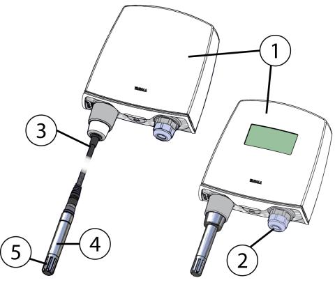
Transmitter Components
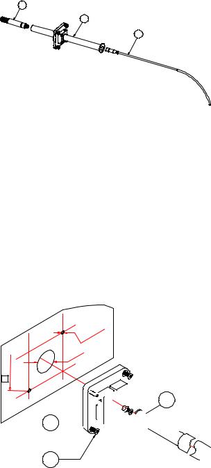
Figure 1 below illustrates the main features of HMT120. On the left is a remote probe model without display, and on the right is a fixed probe model with the optional display. The numbers and arrows indicate the main components of the transmitters.
1007-001
Figure 1 HMT120 Components
The following numbers refer to Figure 1 above:
1= Transmitter enclosure
2= Cable bushing: cable gland, cable grommet, or conduit fitting.
3= Probe cable
4= HMP110 probe
5= Plastic grid filter
See section Options and Accessories on page 73 for accessory parts and their numbers.
12 ___________________________________________________________________ M211244EN-B

Chapter 3 ________________________________________________________________ Installation
CHAPTER 3
INSTALLATION
This chapter provides you with information that is intended to help you install the HMT120.
Opening the Transmitter Cover
1.If the transmitter is not mounted already, hold it against a flat surface.
2.Push on the cover with your thumb, and pull the bottom part of the cover towards yourself.
1301-019
Figure 2 Opening the Transmitter Cover
VAISALA________________________________________________________________________ 13

User's Guide _______________________________________________________________________
Mounting
Wall Mounting
1.Remove the transmitter cover. See section Opening the Transmitter Cover on page 13.
2.Make sure that the HMT120 Humidity and Temperature Transmitter is correctly aligned and attach it directly to the wall with up to four screws (not included in the package).
|
|
1011-149 |
|
|
Figure 3 |
HMT120 Wall Mounting |
|
|
|
|
|
CAUTION |
It is possible to damage the display when tightening the screws, as there |
||
|
is not much room between the upper fastening holes and the exposed |
||
|
display component. Be particularly careful when using a cordless drill. |
||
|
|
|
|
|
|
|
|
NOTE |
Select the size and type of the fastening screws according to the wall |
||
material (for example, wood or stone). Even though using all four screws is strongly recommended, the HMT120 enclosure fastening holes are initially covered with a thin plastic membrane, so less than four screws could be also be used without sacrificing the ingress protection (IP) class of the enclosure. The diameter of the fastening screws is typically between 3.5 and 4 mm.
14 ___________________________________________________________________ M211244EN-B
Chapter 3 ________________________________________________________________ Installation
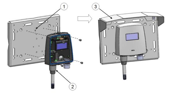
Installation with Rain Shield
The installation kit with rain shield includes a metal mounting plate and a rain shield for the transmitter. Vaisala order code: 215109.
1011-150
Figure 4 HMT120 Installation with Rain Shield
1.Fasten the metal mounting plate to the wall or pole with screws (see Figure 4 above). Note the arrow on the mounting plate. Attach the mounting plate with the arrow pointing upwards.
2.Drill holes for the screws in the HMT120 frame, and fasten HMT120 Humidity and Temperature Transmitter to the metal mounting plate with four (M4) screws.
3.Fasten the rain shield to the metal mounting plate with two (M6) mounting screws.
VAISALA________________________________________________________________________ 15
User's Guide _______________________________________________________________________
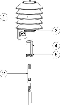
Installation with Radiation Shield
DTR504 with probe installation kit includes a rain/solar radiation shield DTR504 and a plastic installation support for the humidity probe. Vaisala order code: DTR504A. If you already have the DTR504 shield and need only the installation support for the probe, it is available with Vaisala order code 227777.
1.Fasten the probe (item 2 in Figure 5 below) to the installation support with a cable tie (item 5).
2.Insert and attach the support to the radiation shield by tightening the plastic nut (3).
3.Attach the entire radiation shield/probe assembly to a pole mast (pole mast diameter: 30 ... 60 mm/1.2 ... 2.3") with a U-bolt and a support arm.
1303-034
Figure 5 Installation of the Probe with Radiation Shield
The following numbers refer to Figure 5 above:
1 |
= |
DTR504 |
2 |
= |
Probe |
3= Plastic nut
4= Installation support (part no. 227777)
6= Probe
16 ___________________________________________________________________ M211244EN-B
Chapter 3 ________________________________________________________________ Installation
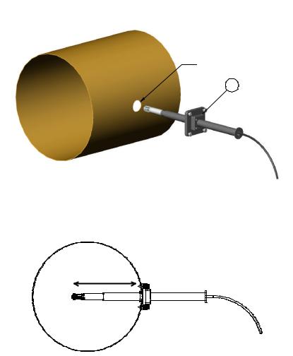
Duct Installation Kit
The duct installation kit includes a plastic pipe with a flange (Vaisala order code: 215619). To install the HMP110 probe with the duct installation kit, drill a hole to the duct wall, assemble the probe to the duct installation kit, slide the probe head through the hole, and attach the flange to the duct wall with four screws. See page 18 for details.
 24
24
1
L
0505-176
Figure 6 Probe Installation with the Duct Installation Kit
The following explanations refer to Figure 6 above: 1 = Tension screw
Distance L can be adjusted and locked in place with the tension screw.
VAISALA________________________________________________________________________ 17
User's Guide _______________________________________________________________________
Probe Assembly with Duct Installation Kit
1
2
3
0505-177
Figure 7 Assembly of the Probe with Duct Installation Kit
The following numbers refer to Figure 7 above: 1 = HMP110
2= Duct installation kit
3= Probe cable
1.Slide the probe cable through the duct installation kit plastic pipe.
2.Attach the probe cable to the HMP110 Humidity Probe.
3.Attach probe assembly to the duct.
Drilling Instructions for Duct Installation Kit
.2 Ø3

 Ø24 42


 3 2
3 2 


1
0505-178
Figure 8 Drilling Instructions
The following numbers refer to Figure 8 above:
1= Mounting screw
2= Tension screw
3= HMP110 assembled in duct installation kit plastic pipe
18 ___________________________________________________________________ M211244EN-B
Chapter 3 ________________________________________________________________ Installation
|
Drill the holes for the duct installation kit as follows: |
|
|
1. |
Use a 24-mm drill bit to drill a hole to the duct wall for the |
|
|
humidity probe. |
|
2. |
Drill holes for the duct installation kit mounting screws around the |
|
|
hole in a square arrangement, 42 mm apart from each other. Use a |
|
|
3.2-mm drill bit to drill the holes for the mounting screws (four |
|
|
ST4.2×16-C-Z DIN 7981 screws). |
|
Probe Mounting Flange |
|
|
The probe mounting flange (Vaisala order code: 226061) is a general |
|
|
purpose mounting flange for 12 mm diameter probes. It can be used to |
|
|
hold the HMP110 probe in a through-wall installation. |
|
|
|
|
NOTE |
The coaxial silicone plug that is delivered with the flange is not suitable |
|
|
for use with the probe cable of the HMT120. |
|
|
|
|
0911-109
Figure 9 Optional Probe Mounting Flange
VAISALA________________________________________________________________________ 19

User's Guide _______________________________________________________________________
Probe Mounting Clamp
The optional mounting clamp makes it easy to install the probe on the wall of the measurement environment. The probe can be detached for calibration simply by loosening the lower screw. You can order a single clamp (Vaisala order code 225501) or a set of 10 clamps (226067).
Installing the entire probe in the measurement environment prevents heat conduction to the sensor, and is the recommended installation method.
|
|
1001-138 |
|
Figure 10 |
Optional Probe Mounting Clamp |
|
|
|
CAUTION |
Attaching the probe mounting clamp to a conductive wall material |
|
|
should be avoided, since the potential galvanic connection to the power |
|
|
supplies and uncontrolled earth current loops could cause measurement |
|
|
errors or even damage to the HMT120 transmitter. |
|
|
|
|
20 ___________________________________________________________________ M211244EN-B
Chapter 3 ________________________________________________________________ Installation
Connections
1
3
2
4
C |
RH |
|
A |
||
T |
||
L |
||
|
||
|
ADJ |
+
-
SHLD
SERVICE PORT CH1-
CH1+
CH2-
CH2+
5
1011-151
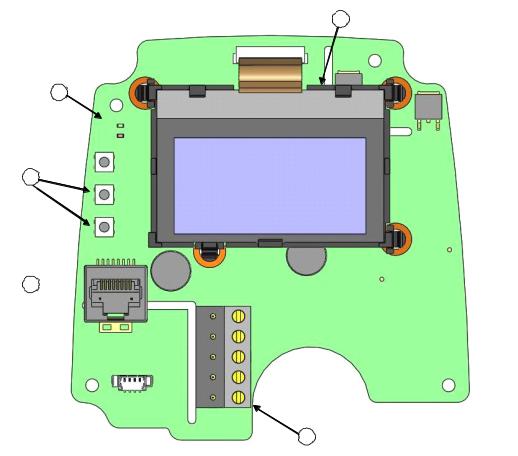
Figure 11 HMT120 Component Board
The following numbers refer to Figure 11 above:
1= Optional LCD display
2= Adjustment buttons
3= Indicator LEDs
4= Service port
5= Field wire terminals
1.Remove the transmitter cover. See section Opening the Transmitter Cover on page 13.
2.Insert the signal wires through the selected cable gland/conduit fitting in the bottom of the transmitter or alternatively through the rubber grommet at the back side of the transmitter.
3.Connect the wires as indicated in Figure 12 and in Table 3 on page 22. Suitable wire size is between 0.5 mm2 and 1.5 mm2.
VAISALA________________________________________________________________________ 21

User's Guide _______________________________________________________________________
NOTE |
If an isolated output is required with current outputs, both channels |
|
require their own power supply. CH1 is always required to be powered |
|
because CH1 is the main output, and the transmitter will not operate if |
|
only CH2 is connected. |
|
|
4.Close the cover by keeping it slightly tilted and first attaching it to the fixing snaps at the top of the enclosure base and then pushing the lower part of the cover firmly forward until it locks. The transmitter is ready for use.
1011-152
Figure 12 |
Isolated Current-Loop Wiring |
|
Table 3 |
Wiring Table |
|
|
|
|
|
Terminal |
Current Output (2-Wire, CH2 Isolated) |
|
1 |
Cable shield (optional) |
|
2 |
CH1- (signal and power supply -) |
|
3 |
CH1+ (signal and power supply +) |
|
4 |
CH2- (signal and power supply -) |
|
5 |
CH2+ (signal and power supply +) |
The numbers 1 ... 5 in the first column of the wiring table refer to Figure 12 above.
22 ___________________________________________________________________ M211244EN-B
Chapter 4 _______________________________________________________________ Service Port
CHAPTER 4
SERVICE PORT
This chapter describes the service port of the HMT120.
Using the Service Port
|
HMT120 motherboard has an 8-pin RJ-45 connector for service use. |
|
|
Service port uses RS-232 signaling levels. Vaisala offers an optional |
|
|
USB cable (Vaisala order code 219685) for connecting the transmitter to |
|
|
your PC. |
|
|
|
|
NOTE |
The service port is intended for short-term use such as calibration. For |
|
|
permanent installation, use the analog output. |
|
|
Connecting a PC to the service port may cause erroneous analog output |
|
|
because of a possible ground loop. Use the service port for service only |
|
|
and disconnect the PC after the service operation. |
|
|
|
|
|
The cable can also provide operation power to the transmitter, so the |
|
|
wires at the screw terminals need not to be connected in order to operate |
|
|
the transmitter. |
|
|
If you have not used the HMT120 USB cable before, install the driver |
|
|
that came with the cable. Refer to section Installing the Driver for the |
|
|
USB Cable below for detailed instructions. |
|
|
Installing the Driver for the USB Cable |
|
|
Before taking the USB service cable into use, you must install the |
|
|
provided USB driver on your PC. |
|
|
1. |
Check that the USB service cable is not connected. Disconnect the |
|
|
cable if you have already connected it. |
|
2. |
Insert the media that came with the cable, or download the latest |
|
|
driver from www.vaisala.com. |
|
3. |
Execute the USB driver installation program (setup.exe), and |
|
|
accept the installation defaults. The installation of the driver may |
|
|
take several minutes. |
VAISALA________________________________________________________________________ 23

User's Guide _______________________________________________________________________
4.After the driver has been installed, connect the USB service cable to a USB port on your PC. Windows will detect the new device, and use the driver automatically.
5.The installation has reserved a COM port for the cable. Verify the port number, and the status of the cable, using the Vaisala USB Instrument Finder program that has been installed in the Windows Start menu.
Windows will recognize each individual cable as a different device, and reserve a new COM port. Remember to use the correct port in the settings of your terminal program.
There is no reason to uninstall the driver for normal use. However, if you wish to remove the driver files and all Vaisala USB cable devices, you can do so by uninstalling the entry for Vaisala USB Instrument Driver from the Programs and Features menu in the Windows Control Panel. In Windows XP and earlier Windows versions the menu is called Add or
Remove Programs.
Terminal Application Settings
The default settings of the HMT120 serial interface are presented in
Table 4.
Table 4 |
Default Serial Interface Setting |
|
|
|
|
Property |
|
Value |
Baud rate |
|
19200 |
Parity |
|
None |
Data bits |
|
8 |
Stop bits |
|
1 |
Flow control |
|
None |
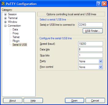
The steps below describe how to connect to the HMT120 using the PuTTY terminal application for Windows (available for download at www.vaisala.com) and a USB serial interface cable:
1.Connect the USB cable between your PC and the service port of the HMT120.
2.Start the PuTTY application.
3.Select the Serial settings category, and check that the correct COM port is selected in the Serial line to connect to field.
NOTE |
You can check which port the USB cable is using with the Vaisala USB |
|
Instrument Finder program that has been installed in the Windows |
|
Start menu. |
|
|
24 ___________________________________________________________________ M211244EN-B
Chapter 4 _______________________________________________________________ Service Port
|
4. |
Check that the other serial settings are correct for your connection, |
|
|
and change if necessary. Flow control should be set to None unless |
|
|
you have a reason to change it. |
|
5. |
Click the Open button to open the connection window and start |
|
|
using the serial line. |
|
|
|
NOTE |
If PuTTY is unable to open the serial port you selected, it will show you |
|
|
an error message instead. If this happens, restart PuTTY and check the |
|
|
settings. |
|
|
|
|
|
6. |
You may need to adjust the Local echo setting in the Terminal |
|
|
category to see what you are typing on the serial line. To access the |
configuration screen while a session is running, click the right mouse button over the session window, and select Change Settings... from the pop-up menu.
0807-004
Figure 13 PuTTY Terminal Application
VAISALA________________________________________________________________________ 25
Loading...