


USER'S GUIDE
Vaisala HUMICAP® Humidity and
Temperature Transmitter Series
HMT100
M210701EN-D

PUBLISHED BY |
|
|
|
Vaisala Oyj |
Phone (int.): |
+358 |
9 8949 1 |
P.O. Box 26 |
Fax: |
+358 |
9 8949 2227 |
FI-00421 Helsinki |
|
|
|
Finland |
|
|
|
Visit our Internet pages at http://www.vaisala.com/
© Vaisala 2009
No part of this manual may be reproduced in any form or by any means, electronic or mechanical (including photocopying), nor may its contents be communicated to a third party without prior written permission of the copyright holder.
The contents are subject to change without prior notice.
Please observe that this manual does not create any legally binding obligations for Vaisala towards the customer or end user. All legally binding commitments and agreements are included exclusively in the applicable supply contract or Conditions of Sale.
________________________________________________________________________________
Table of Contents |
|
CHAPTER 1 |
|
GENERAL INFORMATION............................................................................ |
6 |
About This Manual ................................................................... |
6 |
Version Information ............................................................... |
6 |
Related Manuals ................................................................... |
6 |
General Safety Considerations ............................................. |
7 |
Feedback............................................................................... |
7 |
Product Related Safety Precautions ...................................... |
7 |
ESD Protection ......................................................................... |
7 |
Recycling .................................................................................. |
8 |
Patent Notice ............................................................................ |
8 |
Trademarks ............................................................................... |
9 |
License Agreement .................................................................. |
9 |
Warranty.................................................................................... |
9 |
CHAPTER 2 |
|
PRODUCT OVERVIEW................................................................................ |
11 |
Introduction to the HMT100 Humidity and Temperature |
|
Transmitter.............................................................................. |
11 |
Fixed and Remote Probe Models ....................................... |
12 |
Optional Display .................................................................. |
12 |
HMT100 Transmitter Components...................................... |
12 |
CHAPTER 3 |
|
INSTALLATION............................................................................................ |
15 |
Mounting ................................................................................. |
15 |
Wall Mounting ..................................................................... |
15 |
With Plastic Wall Assembly Plate (Provided)................. |
15 |
With Optional Aluminum Wall Installation Plate............. |
16 |
Installation with Rain Shield ................................................ |
17 |
Installation with Radiation Shield ........................................ |
18 |
Duct Installation Kit ............................................................. |
19 |
Probe Assembly with Duct Installation Kit ..................... |
20 |
Drilling Instructions for Duct Installation Kit ................... |
21 |
Connections............................................................................ |
22 |
CHAPTER 4 |
|
MAINTENANCE ........................................................................................... |
25 |
Replacing the HUMICAP® Sensor......................................... |
25 |
Fixed Probe Model .............................................................. |
25 |
Remote Probe Model .......................................................... |
25 |
Removing and Fastening the Probe..................................... |
26 |
Fixed Probe Model .............................................................. |
26 |
Remote Probe Model .......................................................... |
27 |
VAISALA ________________________________________________________________________ 3
User's Guide ______________________________________________________________________
Calibration and Adjustment................................................... |
28 |
Relative Humidity Adjustment Using Push Buttons............. |
28 |
Adjustment with HM70 ........................................................ |
29 |
Field Checking and Adjustment Using a Calibrated |
|
Reference Probe ............................................................ |
30 |
One-Point Adjustment Using a Calibrator ...................... |
31 |
Two-Point Adjustment Using a Calibrator ...................... |
32 |
LiCl-NaCl Adjustment..................................................... |
32 |
Temperature Field Check and Adjustment by Using a |
|
Calibrated Reference Probe........................................... |
33 |
Adjustment with HMI41 ....................................................... |
34 |
Connections and Selecting the Calibrator Function....... |
35 |
Offset and Gain Adjustments ......................................... |
36 |
HMI41 as a Reference Meter.................................... |
36 |
HMI41 as a Terminal................................................. |
37 |
Troubleshooting.............................................................. |
39 |
Analog Output Tests .............................................................. |
40 |
CHAPTER 5 |
|
TROUBLESHOOTING.................................................................................. |
41 |
Error Mode............................................................................... |
41 |
Current Output..................................................................... |
41 |
Voltage Output..................................................................... |
41 |
Technical Support .................................................................. |
41 |
Return Instructions ................................................................ |
42 |
Vaisala Service Centers ......................................................... |
43 |
CHAPTER 6 |
|
TECHNICAL DATA ...................................................................................... |
45 |
Specifications ......................................................................... |
45 |
Dimensions in mm (inches)................................................... |
49 |
4 ___________________________________________________________________ M210701EN-D
________________________________________________________________________________
List of Figures |
|
|
Figure 1 |
HMT100 Components .............................................................. |
13 |
Figure 2 |
Plastic Wall Assembly Plate (Spare Part No. GM45160)......... |
15 |
Figure 3 |
Plastic Wall Assembly Plate with Aluminum Installation Plate. 16 |
|
Figure 4 |
Installation with Rain Shield (Spare Part No. 215109)............. |
17 |
Figure 5 |
Installation of the Humidity Probe with the Radiation Shield.... |
18 |
Figure 6 |
Probe Installation with the Duct Installation Kit ........................ |
19 |
Figure 7 |
Assembly of the Humidity Probe with the Duct Installation Kit. 20 |
|
Figure 8 |
Drilling Instructions ................................................................... |
21 |
Figure 9 |
HMT100 Connection Board...................................................... |
22 |
Figure 10 |
(1) Isolated Current-Loop Wiring, (2) Voltage Output Wiring... |
23 |
Figure 11 |
Removing the Humidity Probe (Fixed Probe Model)................ |
26 |
Figure 12 |
Removing the Humidity Probe (Remote Probe Model)............ |
27 |
Figure 13 |
Adjustment Buttons .................................................................. |
28 |
Figure 14 |
Location of the MI70 Probe and Cable Connector Ports ......... |
29 |
Figure 15 |
Example of the MI70 Adjustment Menu ................................... |
31 |
Figure 16 |
Example of the MI70 Adjustment Mode Graph Display ........... |
31 |
Figure 17 |
Location of the HMI41 Calibration Connector .......................... |
34 |
Figure 18 |
Accuracy of Temperature Measurement.................................. |
46 |
Figure 19 |
Dimensions HMT100 Fixed Probe Model ................................ |
49 |
Figure 20 |
Dimensions HMT100 Remote Probe Model............................. |
50 |
List of Tables |
|
|
Table 1 |
Manual Revisions ....................................................................... |
6 |
Table 2 |
Related Manuals ........................................................................ |
6 |
Table 3 |
Wiring Table ............................................................................. |
23 |
Table 4 |
Common Problems During Adjustment and Their Remedies .. |
39 |
Table 5 |
Relative Humidity Measurement Specifications....................... |
45 |
Table 6 |
Temperature Measurement Specifications .............................. |
45 |
Table 7 |
Dewpoint Temperature (Calculated) Measurement |
|
|
Specifications ........................................................................... |
46 |
Table 8 |
Accuracy of Dewpoint Temperature Measurement.................. |
46 |
Table 9 |
Operating Environment Specifications ..................................... |
46 |
Table 10 |
Inputs and Outputs ................................................................... |
47 |
Table 11 |
Mechanics Specifications......................................................... |
47 |
Table 12 |
Options and Accessories.......................................................... |
48 |
VAISALA ________________________________________________________________________ 5
User's Guide ______________________________________________________________________
CHAPTER 1
GENERAL INFORMATION
This chapter provides general notes for the manual and the product.
About This Manual
This manual provides information for installing, operating, and maintaining the Humidity and Temperature Transmitter HMT100.
Version Information
Table 1 |
Manual Revisions |
||
|
|
|
|
|
Manual Code |
Description |
|
|
M210701EN-A |
June 2005 - First version |
|
|
M210701EN-B |
April 2006 - Corrected Wiring table (Table 3) |
|
|
M210701EN-C |
May 2007 - Updated Product Overview, |
|
|
|
|
Figure 9, and duct installation kit order code. |
|
|
|
Corrected calibration instructions in the |
|
|
|
Maintenance chapter. |
|
M210701EN-D |
June 2009 - Added spare part numbers of |
|
|
|
|
installation accessories to installation instructions. |
|
|
|
Updated calibration and adjustment instructions. |
Related Manuals
Table 2 |
Related Manuals |
||
|
|
|
|
|
Manual Code |
Manual Name |
|
|
M210185EN-B |
Humidity Calibrator HMK15 User's Guide |
|
|
M210297EN-C |
Hand-held Humidity and Temperature Meter |
|
|
|
|
HM70 User's Guide |
|
M210316EN-A |
HMI41 Indicator and HMP41/45/46 Probes |
|
|
|
|
Operating Manual |
6 ___________________________________________________________________ M210701EN-D
Chapter 1 ________________________________________________________ General Information
|
|
General Safety Considerations |
|
|
|
Throughout the manual, important safety considerations are highlighted |
|
|
|
as follows: |
|
|
|
|
|
|
WARNING |
Warning alerts you to a serious hazard. If you do not read and follow |
|
|
|
instructions very carefully at this point, there is a risk of injury or even |
|
|
|
death. |
|
|
|
|
|
|
|
|
|
CAUTION |
Caution warns you of a potential hazard. If you do not read and follow |
|
instructions carefully at this point, the product could be damaged or |
|
important data could be lost. |
|
|
NOTE |
Note highlights important information on using the product. |
|
|
Feedback
Vaisala Customer Documentation Team welcomes your comments and suggestions on the quality and usefulness of this publication. If you find errors or have other suggestions for improvement, please indicate the chapter, section, and page number. You can send comments to us by e- mail: manuals@vaisala.com
Product Related Safety Precautions
The Humidity and Temperature Transmitter HMT100 delivered to you has been tested for safety and approved as shipped from the factory. Note the following precautions:
CAUTION |
Do not modify the unit. Improper modification can damage the product |
|
or lead to malfunction. |
|
|
ESD Protection
Electrostatic Discharge (ESD) can cause immediate or latent damage to electronic circuits. Vaisala products are adequately protected against
VAISALA ________________________________________________________________________ 7

User's Guide ______________________________________________________________________
ESD for their intended use. However, it is possible to damage the product by delivering electrostatic discharges when touching, removing, or inserting any objects inside the equipment housing.
To make sure you are not delivering high static voltages yourself:
-Handle ESD sensitive components on a properly grounded and protected ESD workbench. When this is not possible, ground yourself to the equipment chassis before touching the boards. Ground yourself with a wrist strap and a resistive connection cord. When neither of the above is possible, touch a conductive part of the equipment chassis with your other hand before touching the boards.
-Always hold the boards by the edges and avoid touching the component contacts.
Recycling
Recycle all applicable material.
Dispose of batteries and the unit according to statutory regulations. Do not dispose of with regular household refuse.
Patent Notice
The HMT100 is protected by the following patents and their corresponding national rights:
Finnish patent 98861, French patent 6650303, German patent 69418174, Japanese patent 3585973, UK patent 0665303, U.S. patent 5607564.
8 ___________________________________________________________________ M210701EN-D
Chapter 1 ________________________________________________________ General Information
Trademarks
HUMICAP is a registered trademark of Vaisala Oyj.
License Agreement
All rights to any software are held by Vaisala or third parties. The customer is allowed to use the software only to the extent that is provided by the applicable supply contract or Software License Agreement.
Warranty
For certain products Vaisala normally gives a limited one-year warranty. Please observe that any such warranty may not be valid in case of damage due to normal wear and tear, exceptional operating conditions, negligent handling or installation, or unauthorized modifications. Please see the applicable supply contract or Conditions of Sale for details of the warranty for each product
VAISALA ________________________________________________________________________ 9
User's Guide ______________________________________________________________________
This page intentionally left blank.
10 __________________________________________________________________ M210701EN-D
Chapter 2 __________________________________________________________ Product Overview
CHAPTER 2
PRODUCT OVERVIEW
Thank you for choosing the Vaisala HUMICAP® Humidity and Temperature Transmitter Series HMT100. This chapter introduces you to its features.
The Vaisala range of relative humidity measurement instruments covers all the applications from ventilation to process control in demanding explosive areas. For more information about other Vaisala relative humidity instruments, please contact your Vaisala representative or visit www.vaisala.com.
Introduction to the HMT100 Humidity and Temperature Transmitter
The Vaisala HUMICAP® Humidity and Temperature Transmitter Series HMT100 measures relative humidity, temperature and dewpoint. It is powered with a 10 ... 35 VDC or 24 VAC input voltage and it outputs an analog signal of either 4 ... 20 mA, 0 ... 1 V, 0 ... 5 V or 0 ... 10 V.
The HMT100 transmitter can be configured to output either one or two quantities, in the following combinations:
-simple RH transmitter
-simple Td transmitter
-RH and T transmitter
-Td and T transmitter
The output quantities and the analog signal type (current or voltage output) are set during order time, and cannot be changed later by the user.
The following accessories are optionally available:
-Wall installation plate (aluminium)
-Duct installation kit
-Rain shield with installation kit
-Rain/solar radiation shield installation kit (for pole installation)
VAISALA _______________________________________________________________________ 11
User's Guide ______________________________________________________________________
Fixed and Remote Probe Models
The HMT100 is available either with a fixed probe (0.1 m probe cable) or a remote probe with different cable lengths (3/5/10 m cable lengths. A 10 m extension cable is also available; see Table 12 Options and Accessories on page 48).
The HMP100 relative humidity probe used in the HMT100 transmitter is fully interchangeable. You can easily remove the probe and replace it with a new one without having to adjust the transmitter.
Optional Display
The HMT100 is also available with an optional one-line display. The display shows the measurement results of selected parameters in selected units (selected at the time of ordering). The parameters are displayed in turns one at a time. The display backlight is turned on and off with a jumper on the transmitter electronics motherboard.
HMT100 Transmitter Components
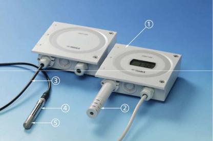
Figure 1 on page 13 illustrates the main features of HMT100. On the left is a remote probe model without display, and on the right is a fixed probe model with the optional display. The numbers and arrows indicate the main components of the transmitters.
12 __________________________________________________________________ M210701EN-D
Chapter 2 __________________________________________________________ Product Overview
0603-048
Figure 1 HMT100 Components
The following numbers refer to Figure 1 above:
1= Transmitter housing; transmitter cover
2= Probe cover
3= Probe cable
4= HMP100 probe
5= Filter
See Table 12 on page 48 for spare part numbers.
VAISALA _______________________________________________________________________ 13
User's Guide ______________________________________________________________________
This page intentionally left blank.
14 __________________________________________________________________ M210701EN-D
Chapter 3 _______________________________________________________________ Installation
CHAPTER 3
INSTALLATION
Mounting
Wall Mounting
With Plastic Wall Assembly Plate (Provided)
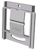
1.Attach the wall assembly plate to the wall with two screws.
2.Press the transmitter down so that it slides along the rails of the mounting plate.
0505-171
Figure 2 Plastic Wall Assembly Plate (Spare Part No.
GM45160)
VAISALA _______________________________________________________________________ 15
User's Guide ______________________________________________________________________
With Optional Aluminum Wall Installation Plate
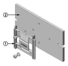
1.Attach the aluminum plate to the wall.
2.Attach the plastic wall assembly plate (provided) to the aluminum plate with two screws.
3.Press the transmitter down so that it slides along the rails of the wall assembly plate.
0505-339
Figure 3 Plastic Wall Assembly Plate with Aluminum Installation Plate
The following numbers refer to Figure 3 above:
1= Plastic wall assembly plate (provided) (spare part no. GM45160)
2= Aluminum wall installation plate (optional accessory, see order form; spare part no. DRW010712)
16 __________________________________________________________________ M210701EN-D
 Loading...